US2022475A - Inserting machine - Google Patents
Inserting machine Download PDFInfo
- Publication number
- US2022475A US2022475A US543261A US54326131A US2022475A US 2022475 A US2022475 A US 2022475A US 543261 A US543261 A US 543261A US 54326131 A US54326131 A US 54326131A US 2022475 A US2022475 A US 2022475A
- Authority
- US
- United States
- Prior art keywords
- envelope
- shaft
- arm
- arms
- fingers
- Prior art date
- Legal status (The legal status is an assumption and is not a legal conclusion. Google has not performed a legal analysis and makes no representation as to the accuracy of the status listed.)
- Expired - Lifetime
Links
- 210000003811 finger Anatomy 0.000 description 58
- 230000007246 mechanism Effects 0.000 description 56
- 230000010355 oscillation Effects 0.000 description 11
- 230000009471 action Effects 0.000 description 7
- 230000000153 supplemental effect Effects 0.000 description 7
- 230000005484 gravity Effects 0.000 description 4
- 230000015572 biosynthetic process Effects 0.000 description 2
- 238000003780 insertion Methods 0.000 description 2
- 230000037431 insertion Effects 0.000 description 2
- 101100298295 Drosophila melanogaster flfl gene Proteins 0.000 description 1
- 229910000831 Steel Inorganic materials 0.000 description 1
- 230000003190 augmentative effect Effects 0.000 description 1
- 230000006835 compression Effects 0.000 description 1
- 238000007906 compression Methods 0.000 description 1
- 238000010276 construction Methods 0.000 description 1
- 230000001934 delay Effects 0.000 description 1
- 230000000694 effects Effects 0.000 description 1
- 230000000977 initiatory effect Effects 0.000 description 1
- 230000002265 prevention Effects 0.000 description 1
- 230000007480 spreading Effects 0.000 description 1
- 239000010959 steel Substances 0.000 description 1
- 210000003813 thumb Anatomy 0.000 description 1
- 239000002699 waste material Substances 0.000 description 1
Images


Classifications
-
- B—PERFORMING OPERATIONS; TRANSPORTING
- B43—WRITING OR DRAWING IMPLEMENTS; BUREAU ACCESSORIES
- B43M—BUREAU ACCESSORIES NOT OTHERWISE PROVIDED FOR
- B43M3/00—Devices for inserting documents into envelopes
- B43M3/04—Devices for inserting documents into envelopes automatic
Definitions
- This invention relatesgenerally supplemental inserting arrangement.
- the present invention is particularly useful" where it is desired to mail large or relatively small commercial quantities of letters.
- a practical machine In commercial work of this type a practical machine must possess a high degree of accuracy, speed,
- Another object is to provide improved adjustable means for positioning the paper prior to folding so that if desired the outside end edge may be offset from the adjacent folded edge to permit easy opening of the letter and also to avoid having a line of fold fall on a line of type, this adjustable means also being adapted to permit accurate operation on various size sheets.
- a further object is to provide improved means whereby the flap of an envelope will be positively lifted from the envelope body and then the envelope positively opened to permit the insertion of the insert or letter.
- a further object in this respect is to have these functions cooperate with the folding mechanism in an improved manner so that an insert upon issuing from the folding mechanism will be properly and easily inserted within the opened envelope.
- Another object is to provide an improved arrangement whereby the envelope flap lifting is utilized in the opening-of the envelope body. Still another object is to provide in proved 'means for positively inserting the insert- .within the envelope and to have relative movement between the insert and envelope in 5 the general movement of either the envelope or insert, this being conducive to high speed operatloir without sacrifice of positive operation.
- a more specific object is to have ftlteinsert move toward the open envelope which 10 then moves in the same direction as that in which theinsert moved toward the envelope although it will of course be understood that the envelope could be moved toward the insert and the two then moved in the direction of movement of the 15 envelope. In either case, the relative movement between the two elements with subsequent absolute movement of both in the general direction of relative movement, is conducive to rapid, eflicient and smooth operation.
- a further object is to provide an improved arrangement whereby additional inserts may be inserted within the envelope without requiring any inserting operations other than the one whichis used for the single insert.
- a more specific object of the invention is to provide improved means whereby the additional in serts, such for instance as postcards or the like, or even pre-folded letter sheets, may be positioned within the initial sheet.
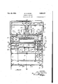
- Fig. 1 is a side elevation of the machine
- Fig. 215 a plan view of the machine
- Fig. 3 is a rear elevation of the upper portion of the machine looked at from the left side of Fig. 1;
- Fig. 4 is a horizontal section from line 4-4 of Fig. 1;
- Fig. 5 is an enlarged vertical section of the lower portion of the machine taken on line H of Fig. 4;
- Fig. 6 is an enlarged central vertical section of the upper part of the machine taken substantially on the line 6-6 of Fig. 3;
- Fig. 7 is a view of the envelope opening mechanism looked at in the direction of the arrow 1;. in Fig. 5;
- Fig. 8 is a similar view looked at in the direction of the arrow b, Fig. 5;
- Fig. 9 is a vertical section of one part of the upper portion of the machine taken on the line 9-9 of Figs. 3 and 10;
- Fig. 10 is a plan view of Fig. 9 with certain parts removed to show the gear and cam arrangement;
- Fig. 11 is an enlarged elevation of one of the yieldable fingers which overlie the top sheet of the letter pile;
- Fig. 12 is a horizontal section taken on line
- Fig. 13 is an enlarged vertical section of the portion of the element which initially engages the envelope flaps to lift the same.
- Paper feeding mechanism.-As shown in Fig. 1 the machine comprises a base I provided with parallel sides 2 and 3 preferably of thin plate steel secured to base I by any suitable means.
- a lower adjustable bracket Illa is provided on the paper table and it will of course be understood that any number of desired guides may be employed.
- This table is supported for vertical adjustment by a pair of chains ll connected one to each side of the table and leading up and down over a pair of sprockets l2 secured to a shaft l3 which is journalled in the horizontal U-bracket l0.
- Preferably relatively small weights l3, Fig. 1 are secured to the free ends of the chains although if for any reason it is desired to counterbalance the weight of the paper and table, the size of the weights may be made accordingly but normally this is not necessary or desired.
- a ratchet I4 is secured to one end of shaft I3 A and is actuated by a pawl l5 pivotally connected as at It to an arm on a shaft ll.
- This shaft in turn is continuously oscillated by a link l8 pivotally connected at one end to an arm IS on shaft I1 and at its other end to an arm 20 secured to a shaft 2
- has an arm 22 rigid therewith. The outer end of this arm carries a roller for constant engagement with a cam 22a mounted upon a camshaft 23. The drive for this continuously rotating camshaft will be described later. Referring again to Fig.
- pawl l5 constantly oscillating it is adapted, subject to suitable control, to engage successive ratchet teeth to move the paper rack upwardly as by the chains until the top of the pile of paper engages a finger 24 adjustably threaded in an arm 25 which is secured to shaft l1. Further rotation of the ratchet causes arm 25 to be raised to a predetermined position thereby limiting the counter-clockwise oscillation of shaft l1 and accordingly preventing pawl 15 from engaging another ratchet tooth, the ratchet of course being held during this time by a stop pawl 26. Limitation of oscillating movement of the pawl does not restrain action of the cam actuating mechanism for the reason that Fig. 9, arm 22 will be held away from cam 22a whenever th'e-paperis fed to its full up position.
- finger 24 will gradually assume a lower position and thus allow actuating pawl l5 to have increasing counter-clockwise movement until it can completely engage another ratchet tooth whereupon the ratchet will be then partially rotated to again raise the paper table and in so doing cause finger 24 to move upwardly thereby preventing engagement of another ratchet tooth until a sufficient amount of paper has again been fed.
- the rear side of the pile of paper is guided by angle pieces 4a supported for inward and outward movement upon a vertical guide 4b.
- the top of these angle pieces 4a located one at each of the rear corners of the pile of paper, is provided (Fig. 11) with a small axially adjustable yieldable finger 40 which slightly overlies the edge of the paper.
- the normal position of the top of the pile of paper is slightly below the fingers 40, thereby permitting free action of the top sheet during feeding thereof and yet assisting in preventing more than one sheet being fed which might otherwise be caused by the blast of air which is directed against the inner top portion of the pile as through nozzles 28, Figs. 1 and 2.
- Suction sheet feeding mechanism comprises, Fig. 6 a transversely disposed pipe 29 rotatably supported in the outer ends of a pair of arms 30 secured to a shaft 3
- is connected through an arm and linkage connection 32 to the continuously rotating camshaft 23 which has been previously mentioned in connection with Fig. 9.
- This pipe is provided with downwardly projecting suction tubes 34 preferably two in number and spaced apart by a rib.35 which is adapted to prevent the paper from bulging upwardly between the two suction elements.
- the suction pipe is connected through a timing valve 36 and suction pipe 31.
- An adjustable constant bleed valve 38 is disposed in suction pipe 31 so as to control the degree of vacuum in accordance with the particular quality of paper or other conditions and independently of the speed of operation of the suction pump 39, Fig. 1, to which pipe 31 is connected.
- the discharge side 48 of the pump is connected Fig. 1 and 2, to blowers 28.
- the cam for actuating shaft I1 is timed so as to raise arm 25 and its stop finger 24 and at the same time open suction valve 36, this opening operation being effected by the provision of an arm 4
- This means comprises, Figs. 1 and 2, a bracket 44 secured to the outer ,closed end of suction pipe 28, this bracket having spaced bearings through which a rod 45 passes, the lower end thereof being mounted, Fig. 5, for pivotal movement about a transverse pin 46 secured on the inside of side plate 2.
- suction valve 36 is timed so that when arms 38 have raised a sheet to the feeding rollers 48 the suction will be cut oil and the suction grip broken either by a suitable vent in valve 36 or by leakage around the suction elements 34, the suction release being in suflicient time to permit the paper to be properly gripped by rollers 48.
- Sheet positioning mechanism This mechanism functions as the sheet is fed rearwardly by rollers 48 over table 49.
- the folding blades have a fixed path of travel thereby insuring simplicity of construction and operation, I have provided means for positioning the sheet of paper relative to the folding blade, thereby obtaining any desired location of the fold'on the sheet or of adjusting the location of fold to suit various sizes of sheets.
- This improved positioning mechanism also permits the paper to be moved entirely free of the feeding rollers before the folding operation is performed.
- This cam is so angularly related to the mechanism so far described and its contour is such that when rollers 48 are feeding the paper rearwardly (to the left) shaft 56, Fig. 6, will be swinging arm 55 to the right, thereby moving positioning fingers 52 forwardly. These fingers are maintained in their down position due to the left end of link 58 being temporarily frictionally held, thereby causing arm 51 .to move in a clockwise direction and similarly exert a downward movement on the positioning fingers 52.
- a small finger 52', Fig. 10 extends laterally from arms 52 so as to engage the top side of guides 5
- the position of the sheet is controlled by the provision of a fixed abutment in the form of an adjustable set screw 1
- a fixed abutment in the form of an adjustable set screw 1
- which is secured to the outer end of shaft 56.
- the paper upon being positioned longitudinally is also positioned laterally, Fig. 6, by two jogger arms 61 secured to a shaft 88 suitably journalled on the inside of side plate 8'.
- a cam 68 engages a follower arm 68a. which is secured to and extends laterally from shaft 68.
- This cam is secured, Figs. 2 and 9, to camshaft 23 and is so designed and timed that jogger arms 81 move outwardly as the paper is fed over table 48 but as the paper reaches substantially its folding position the cut away portion of the cam allows arm 68a to move upwardly under tension of a semi-coil spring wire 68a, Figs.
- the folding mechanism.--This mechanism includes, Fig. 6, a transverse slot 12 formed between the rear turned down edge of table 48 and the forward turned down edge of the continuation 18 of table 48.
- the slot is immediately over and adjacent to the initial folding blade 15.
- This blade disposed across the entire width of table 48, is supported upon the outer end of a pair of side arms 16 which are fixed to an oscillating shaft 11 journalled within the side plates.
- This shaft is actuated, Fig. 9, by an arm 18 fixed thereto and whose outer end is actuated by a cam 18.
- mounted upon a pair of arms pivot-ally supported about shaft 86, will move forwardly and in so doing will cause a plurality of transversely spaced resilient fingers 81, secured to arms 85 for movement therewith, to engage the sheet near its initially folded edge. Due to the resiliency of these holding fingers folding blade 8
- Envelope opening mechanism The completely folded sheet upon passing from the front side of folding rollers 84 is carried downwardly and inserted within an open envelope which in the specific embodiment of the invention herein described is moved upwardly to meet the folded sheet or insert.
- the operating means for feeding and opening the envelopes will be first described.
- an inclined envelope feeding rack comprising two laterally spaced bottom bars 88 and two side bars 8
- carry an abutment plate I88.
- This abutment disposed substantially at right angles to the envelope guides, engages the first envelope of the group of envelopes placed upon the guides and is cut down along the lines I8I which terminate in a notch I82 of substantially rectangular formation.
- the top outer corners I83 are bent slightly rearwardly with respect to the main body portion of the envelope. Inasmuch as the envelopes are placed in the rack with their fiaps forwardly it is seen that the rearward pressing action of the corners I83 will tend to throw the V corner of the fiap forwardly away from the envelope body.
- the envelopes are preferably of the type in which the flap is of substantially V shape formation having an obtuse angle.
- any suitable spring or weight may be placed behind the rearmost envelope and supported on the envelope guides so as to move by gravity as the envelopes are fed, such an arrangement being shown generally at I84.
- Envelope flap opener To open the envelope fiap there is provided a pair of arms I 85 journalled on a shaft I86 and rotatably carrying in their front free ends a cross rod I 81 which is normally biased in a clockwise direction by a spring I88, Fig. 8. The opposite ends of the spring engage one of the arms I85 and a suitable collar on shaft I81.
- the other end of shaft I 81 carries, on a small arm, a stop pin I88 adapted to engage the under side of the adjacent side rod I85 so as to limit the inward movement, Fig. 5, of the flap opener generally indicated at I I8.
- This fiap opener as shown in Figs. 7 and 8 is of relatively narrow width and is rigidly secured to the yieldable shaft I81.
- the lower portion of the opener is reversely curved and terminates in a slightly rearwardly inclined transverse edge III from which a guard H2 projects forwardly and downwardly.
- Extending upwardly from the yieldable shaft I81 is a flap holding portion N3 of somewhat narrower extent than the opener blade III.
- the portion H8 urged forwardly by a spring H9 is slidably guided by a member I20 which is supported for oscillation on a shaft I2 I.
- This shaft is secured to the brackets 93 while a portion I 22 extends upwardly from the member I20 for yieldable engagement with a compression spring I23.
- This spring is supported by a bracket I24 secured to a transverse bracket I25 in turn mounted on the side arms 33.
- An adjustable screw I26 is adapted to provide an adjustable stop for the portion I22 and thereby limit upward movement of the presser mechanism II1.
- the fiap opener After the fiap opener has raised and passed the portion II8 of the presser mechanism the latter will quickly drop thereby insuring that the second and succeeding envelopes will not be carried upwardly with the first envelope. Prevention of upward movement of the second envelope is also accomplished in that the opener blade III tends to crowd back the second and other envelopes when the blade III initially engages the presser mechanism.
- envelope pickup mechanism I21 ascends to lift a previously opened envelope. With the pickup mechanism raised the flap opener is free to complete its operation which is as follows. As the fiap opener ascends its shaft I01 engages and pushes forwardly a plurality of transversely spaced yieldable flap holding guards I28, these guards being mounted on a resiliently held shaft I29 which is pivotally mounted in a bracket extending forwardly from the lower bars 80. These guards are normally biased toward shaft I01 and are curved as shown so that as the shaft rises it moves the guards forwardly to permit the fiap to be folded back in open position against the upwardly extending portion H6 01' the tripper mechanism.
- the pickup mechanism comprises a pair of arms I30 journalled upon a shaft I3I.
- the forward endsof 'these arms rigidly carry stationary fingers I32 while cooperating movable fingers I33 are carried on a shaft I33 pivotally supported in the arms I30.
- links I34 pivotally connected to arms I35 and shaft I33 to oscillate fingers I33, the other end of the links being pivotally connected to arms I36 secured to a shaft I 31 which is pivotally carried by arms I30.
- shaft I31 has an arm- I36 secured thereto, this arm being connected by a tension spring I38 to the outer free end of an arm I30 which is freely supported for oscillation upon shaft I3I.
- Upper and lower stops generally indicated at I40 and I are provided for limiting the movement of arm I33 with the result that as arms I30 swing 5 upwardly the arm I38 will engage stop I40 and be held against movement during continued movement of arms I30 with the result that the pivot I31 will ultimately pass to the upper side of the center line of spring I 38, thus causing torque to 10 be exerted on bellcrank I36 so as to move the same in a clockwise direction and thereby move link I34 forwardly to open the pivoted gripping fingers I33.
- This opening movement occurs when arm I30 is in substantially the dotted line position 15 shown at I42, thereby releasing the envelope which it is assumed is being carried up.
- the arms I30 then repeat the previously mentioned raising operation and during its initial 35 upward movement the flap opening mechanism IIO will remain stationary until the envelope .whichis being lifted is clear of the pile of envelopes at which time the opener IIO then raises simultaneously with arms I30 to open the flap of 49 the next envelope which is thereby prepared for the pickup mechanism I21 on its next down stroke.
- the actuating mechanism for swinging pickup arms I30 and opening arms I05 comprises (lower part of Fig. 5) an arm' I43 sup- 5 ported for oscillation upon a shaft I44 and having a roller I45 riding upon a cam I46, this cam being continuously driven in a counterclockwise direction by a shaft I41.
- the extent of the slot in link I 50 is such that the desired upward movement of the envelope pickup fingers may be had prior to a positive lifting engagement between the link I50 and the pin I52.
- a spring I54 is connected to pivot I5I and to a stationary part of the envelope rack 80, thereby providing the actuating force for moving the pickup mechanism downwardly.
- This means comprises, Fig. 'I, an inner pair of transversely spaced yieldable envelope supporting guides I56 which as shown in Fig. 5 are rearwardly curved at their lower ends. There is also provided, Fig.
- a pair of outer but somewhat shorter resilient supporting fingers I 51 are rigidly supported upon elements I58 which constitute the positive mechanical means insertable within the envelope body for opening the same, these elements being rigidly supported upon a cross bar I59 in turn supported by the insertable elements I58 have their inner corners I60 slightly curved rearwardly so as to lie more nearly in a plane between the two sides of the envelope body.
- the opening action is effected in that the forward pickup fingers I32 move upwardly behind the plates I58 approximately along the path as indicated in Fig. 7 at I6I while the envelope fiap is on the front side of the guiding supports Ill.
- the result is that the envelope as atlcally indicated at I62 will have the initial portion of its fiap I83 positively moved beneath the inner corners of plates I58 due to the forward gripping fingers I32 positively moving behind these plates.
- the flap is slid or pinched between the resilient supports I82 and plates I58 so that as the envelope continues upwardly the top edge I64 of the front side of the envelope is left free to pass over the front side of plate I58. 'To assist the outer envelope edge I64 in passing on the outside of plates I58 the flap opening mechanism, Fig.
- the further opening of the envelope is effected by the provision of flanges I66 projecting forwardly from each of plates I58.
- the envelope is carried-upwardly so that its flap reaches approximately the dotted line position I61 whereupon the letter is then inserted within the envelope.
- Inserting mechanism Referring to Fig. 6, as the letter or insert moves forwardly from rollers 48 it is received in a transfer mechanism in the form of a basket I10.
- This basket comprises a .transversely disposed plate I" supported upon a pair of spaced arms I12 which are rigidly secured to an oscillating shaft I13.
- the edges of plate "I are provided with side fianges while yieldable holding fingers I13 are also supported by an upward extension of arms I12.
- the letter upon being received beneath the free ends of fingers I13 is held in position by being pressed on plate "I whereupon through suitable linkages to be described later the basket swings downwardly until it engages the top front portion I15 of the envelope opening plates shown in Figs. 5 and '1 at I58.
- an inserter proper I16 then functions to push the letter or insert into the opened envelope.
- the inserter proper comprises a support I11 reciprocally guided on a rod I18 of preferably rectangular cross-section, this rod being secured to a pivotal shaft I18.
- a pushing element I normally yieldably biased in a clockwise direction around a pivotal support I8I is carried by 5 support I11.
- This pusher has an offset member I82 for engaging the top edge of the insert or inserts depending ,upon whether a postcard or other matter is associated with the letter.
- This mechanism is so controlled by linkages, to be de- 10 scribed presently, that after the basket has moved down to engage surface I15 the pusher I80 moves rearwardly between the fingers I13 to engage the front side of the insert and then begins downward movement, thereby causing the offset 15 I82 to engage the top edge of the insert and push the same downwardly into the envelope.
- the portion I80 also moves into the body of the envelope, thereby providing for the letter a very substantial support and guidance which is desir- 20 able especially if the letter is of relatively thin paper.
- the inserter I80 has orbital movement similar to an ellipse.
- the actuating mechanism for the transfer basket and inserter is associated with the actuating mechanism for the second folding blade, Fig. 6.
- the shaft III is oscillated by link I48, arm I43 and cam I46.
- Rigidly attached to shaft I3I for oscillation therewith is an arm I83 which as shown in Fig. 6, is connected by a link I84 to an 40 arm I85 rigidly secured to shaft I13.
- a link I86 connects arm I85 with the folding blade arm 85.
- a second arm I81 secured to shaft I13 is connected by a link- I88 to an arm I 88 which is fixed to shaft I18.
- Gripping mechanism for moving envelope and insert downwardly- This mechanism comprises as shown in Figs. 5 and 4 a pair of transversely disposed arms 200 secured to a shaft 20I for oscillation therewith. Front gripping fingers 202 nor- 70 mally fixed with respect to arms 200 are adapted to cooperate with movable gripping fingers. 203 which are mounted upon a pivotal shaft 204. As shown in Fig. 4 an arm 205 is securedto the outer end of shaft 204 and is connected by a link 208 7 to a bellcrank 201 which is pivoted at 208 to one of the arms 200. A spring 208 connected to one arm of bellcrank 201 is attached to an arm 2l0 which is freely journalled on shaft 20l.
- Upper and lower stops 2 and 2l2 limit the angular movement of arm 2
- the operation of this mechanism is the same as the previously described mechanism for controlling the gripping fingers of the envelope lifting mechanism so that it will sufiice to state that as shaft 20l is oscillated, Fig. 1, by an arm 2l3 connected to link 2 through an arm 2l5 on the continuously counter-clockwise rotatable camshaft I41, the arms 200 will cause pivot 208, Fig. 5, to laterally pass the center line of spring 209 and accordingly cause the fingers 202 and 203 to open and close.
- the actuating mechanism is so timed that the gripping fingers 203move upward- .ly in open position so as to receive the lower edge portion of the envelope and insert and at that time the pivot 208 is moved'past the center line of spring 209 so as to close, whereby the envelope is positively moved downwardly from the support and opener plate I58.
- Receiving mechanism for completed envelopes comprises as shown in Figs. 4 and 5 a stationary receptacle having a bottom 225 and sides 226 supported in any suitable manner as for instance by a rod 221 secured to the side plates 2 and 3.
- An opening 228 is formed in the rear edge of bottom 225.
- a pair of arms 229 secured at spaced points to a rocking shaft 230 carries two gathering and pushing fingers 23l which oscillate back and forth in opening 228. This oscillation is effected, Fig. l, by an arm 233 secured to shaft 230 and connected by a link 234 to link 214.
- This actuating mechanism is so timed that when the gripping fingers 202, 203 move an envelope down, gathering fingers 23l will be disposed at their rearmost position, thereby causing the envelope to pass on the front side of the fingers 23 l
- the gripping fingers are released and gathering fingers 23l start to push the envelope into the body of the receptacle.
- the envelope is initiallyreceived in the receiver on two lateral portions 225' of the bottom 225 thereby providing the necessary support for the envelope during forward movement of fingers 23L
- the envelopes accumulate in the receiver with their flaps lifted and overlapping each other thus being in condition to have their gummed edges easily moistened and sealed either by hand or machine.
- a supporting plate 235 is provided within the receptacle so as to maintain the envelopes in a substantially vertical position without falling forwardly onto the floor of the receptacle.
- This plate is supported on a transverse bar 236 so as to be movably guided on lateral flanges disposed at the upper edges of the sides 226.
- the supporting plate and bar are yieldably. frictionally held by provision of a small friction block 231 urged upwardly into engagement with the un-.
- Supplemental insert mechanism-To include with the letter an additional insert such as a postcard, blotter, pre-folded letter or any other desired matter and to place the same in a psychologically as well as physically advantageous position within the outer or enclosing letter there is provided an improved supplemental inserting 5 mechanism arranged to cooperate most eflicient- 1y with my improved machine.
- a pair of transversely spaced bottom guides 250 suitably supported by a pair of angle brackets 25l whose 10 upper ends support or carry lateral guides 252.
- Each bracket thus carries one bottom and one lateral guide.
- the brackets are supported by arms 253 for axial adjustment along a transverse rod 254 which is secured to the side plates 2 and 3. This adjustability permits the machine to handle any width of supplemental insert.
- the forward ends of the bottom guides 250 are provided with downwardly curved portions 255 which terminate in rearwardly extending guides 256 which overlie and guide the letter sheet initially fed beneath the first folding blade 15.
- the postcards when placed within the rack are held at their front end by a pair of yieldable lateral fingers 251 and by a pair of inwardly projecting feeler fingers 260 which are readily yieldable in order to permit the first card to be drawn off relatively easily.
- the cards are held at their rear by a supporting plate 26l which is carried by a rod 262 projecting upwardly from 30 a movable supporting carriage 263.
- This carriage is yieldably slidably mounted upon and between two guides 264, Fig. 1, which are supported at their front ends by the side frames 2 and 3. As shown in Figs.
- a shaft 265 is provided with a pair of feed sprockets 266 over which a chain 261 secured to carriage 263, passes around sprockets 266 from their under sides and thence rearwardly over the top thereof and down over an idler pulley 268 carried by carriage 263.
- the feeding mechanism for the driving feed sprockets 266, Fig. 2 is of the same general type as described for the letter sheet feed in that shaft 265 is provided with a ratchet 268 held against reverse rotation by a stop pawl 269 and intermittently driven by a pawl 210 which is pivoted at 212 to an arm fixed to a shaft 2".
- Shaft 2H is in turn operated through an arm and a slotted link 213 connected to oscillating arm 2 13.
- a stop arm 214, Fig. 6, similar to the stop 25 of the letter 513 sheet feed is adapted to engage the first card of the pile thereby limiting the actuation of ratchet 268.
- a spring 215 connected to a suitable arm on shaft 2" urges stop arm 214 against the cards.
- rod 213 can reciprocate freely without affecting the stop arm, this free reciprocation being permitted by the slot in rod 213.
- the upper end of its slot will engage the pin of the cooperating arm and cause the stop arm to swing forwardly away from the cards.
- a pair of suction elements 216 supported by arms 211 which are secured to a shaft 213, this shaft being oscillated, Fig. 1, by an arm 219 through links 200 and 32 connected to the continuously rotating camshaft 23.
- These elements are so arranged that when the suction elements 216 move into contact with the first card the continuous suction through the suction elements causes them to take hold of the card whereafter the suction elements move forwardly to carry the card therewith.
- the degree of suction is augmented by reason of timing valve 30, Fig. 2, being closed at this moment thereby allowing a greater vacuum for the supplemental insert, this, however, being finally controlled by valve 38.
- stripper fingers 28! carried by and projecting upwardly from the first folding blade 15. These fingers are adapted to pass one between the slightly transversely spaced suction elements when the folding arm is in its raised position and the others on each side of the suction elements. As the card is stripped it will fall by gravity to the left of folding blade 15 and onto the unfolded sheet extending across the folding opening 12. The card may fail against the rear face of the folding blade, thereby being in position to be engaged by the rearwardly extending pusher plate 282 but irrespective of whether the card initially engages the folding blade the card will be positively engaged and pushed through with the letter as the folding blade moves downwardly.
- This positive engagement is effected in that as the letter sheet is bent downwardly toward the folding rollers by the folding blade the card will drop down with the fold until finally it will rest against the face of the folding blade and be positively moved therewith by the pusher element 232.
- the card then passes through the remainder of the operations in the manner described for the folded sheet, it being noted that the card is positioned at the initial fold and is inside of the letter so as to obtain the advantages previously described.
- an electric motor 290 drives pump 39 through a belt.
- the pump in turn drives a chain 2!, a shaft 292, a chain 293 and a shaft 294.
- This last shaft supports and drives the upper one of rollers 84, Fig. 6.
- the cooperating lower roller is held against the upper one by yieldably supported bearing blocks 295 and is driven, Fig. 3, through gears 296 and 291.
- Gear 231 drives a shaft 293 which carries the lower roller.
- the upper rollers are driven from shaft 294 as by gears 299, 300 and 30!, the last two gears driving shafts 302 and roller shaft 301.
- a gear 304 on shaft 301 drives, Fig. 10, a gear 304 on the other roller shaft 303.
- Shaft 303 is supported in yieldable bearing blocks 308 similar to the other blocks 295.
- roller shaft 301 carries a sprocket for driving a chain 309 around an idler 3
- This shaft is also yieldingly pressed against the upper feed roller in the same manner as the other roller shafts.
- the upper feed rollers are driven from the lower one by gears 3".
- Cam shaft 23, Figs. 6 and 10 is driven from folding roller shaft 301 by gears 30!, 300, shaft 302, gears 3l5 and M6, gear 3 being connected to cam shaft 23 which also carries cam 69 for the lateral jogger arms.
- the gears for the envelope opening, pickup and inserting devices comprise, as shown in Fig. 5, a gear 320 on driving shaft 292 meshing with a gear 32l to drive a shaft I44, gears 323 and 324 and cam shaft I41.
- An envelope inserting machine comprising,
- means for inserting matter therein including a mechanical element adapted to move into the inside of the envelope with the matter and then withdraw, and an abutment device movable with said mechanical element and adapted for engagement with the top edge of the insert matter during the inserting operation.
- An envelope inserting machine comprising, in combination, means for lifting an envelope fiap, mechanical means insertable within the body of the envelope, means for moving an insert against said mechanical means and then sliding fire insert thereover during the inserting opera- 3.
- An envelope inserting machine comprising, in combination, means for lifting an envelope flap, mechanical means insertable within the body of the envelope, means for moving an insert against said mechanical means and then sliding the insert thereover during the inserting operation, said latter means including an orbitally movable -mechanical element insertable in the envelope with the insert.
- An envelope inserting machine comprising, in combination, an envelope support, and curved means for lifting the envelope flap by causing the free edge thereof to curve when initially engaged.
- An envelope inserting machine comprising, in combination, means for slightly bulging the envelope body to bias the free edge of the envelope fiap away from the body, and curved means for folding back the flap of the envelope.
- An envelope inserting machine comprising, in combination, means for lifting an envelope flap, and a plurality of members held in close relation to each other and between which the envelope flap is adapted to be moved, and means for thereafter moving one of said members into the inside of said envelope and for causing the other member to be disposed on the outside of said envelope.
- An envelope inserting machine comprising, in combination, means for lifting an envelope flap, means for moving the envelope upwardly, means for opening the envelope body during its upward movement, means for inserting matter means for receiving the released envelope and In the envelope while in its upper open posltlon, moving the some out o! the path of succeeding means for then engaging the lower portion of the envelope.
Landscapes
- Folding Of Thin Sheet-Like Materials, Special Discharging Devices, And Others (AREA)
Description
Nov. 26, 1935. M. H. MOORE 2,022,475
INSERTING MACHINE Q Filed June 10, 1931 8 Sheets-Sheet 1 IN VENT OR M77on fM/zm-e #944.
17/ A. aam-ld/nm.
Nov. 26, 1935. H. MOORE v 2,022,475
' 'INSERTING MACHINE I Filed June 10, 1931 8 Sheets-Sheet 2 INVENTOR Mfian A! maoreflzd.
g/A. Maura-1110:;
Nov. 26, 1935. M H, RE 2,022,475
mssnwme MACHINE Filed June 10, 1931 a Sheets-Sheet 3 M. H. MOORE INSERTING MACHINE Nov. 26, 1935.
Filed June 10, 1931 8 Sheets-Sheet 4 M w 3 w 1| e m m a w |I l I ww m. m f
NOV. 26, M H MQQRE INSERTING MACHINE Filed June 10, 1931 8 Sheets-Sheet 6 INVENTOR flfl/fanf/ 4/0011? Jail Nov. 26,1935. M. H. MOORE INSERTING MACHINE 8 Sheet'S-S heet 7 Filed June 10, 1931 IN VENT OR M/forrAf/Iwre Jbcd.
V- 1935- M. H. MOORE INSERTING MACHINE Filed June 10, 1931 8 Sheets-Sheet 8 300 INVENTOR Ali/0x24! I491! decaf PatenteirNovi 26, 1935 UNITED STATES PATENT OFFICE INSERTIN G MACHINE v Milton H. Moore, deceased, late of Hartford, Conn., by Mary L. Moore, administratrlx, Hartford, Conn., assignor to Multlsembler Corporation, New York, N. Y.
Application June 10, 1931, Serial No. 543,261
1 (ctss-v-s) This invention relatesgenerally supplemental inserting arrangement.
The present invention is particularly useful" where it is desired to mail large or relatively small commercial quantities of letters. In commercial work of this type a practical machine must possess a high degree of accuracy, speed,
flexibility in being able to operate not only with paper of different quality and thickness but also in being readily adaptable to large or small quantitles, and in general to be easily operated and to function positively and continuously so as to avoid unnecessary delays. Failure to meet with these and other conditions renders a machine commercially impractical for this type of work. Due to the existing types of machines lacking the necessary degree of speed coupled with positiveness and accuracy of operation which are required, or their inability to have all of the necessary elements function with a high degree of smooth cooperation, a great amount of inserting is still performed by hand in which case the let ters are pro-folded either by machine or hand while in still other cases pre-folded letters are inserted by machine.
It is an object of the invention to provide an improved combination of elements whereby their functions are so coordinated in an improved manner as to perform efiiciently thefunctions of folding a flat letter sheet, opening an envelope and inserting the folded sheet therein. Another object is to provide improved adjustable means for positioning the paper prior to folding so that if desired the outside end edge may be offset from the adjacent folded edge to permit easy opening of the letter and also to avoid having a line of fold fall on a line of type, this adjustable means also being adapted to permit accurate operation on various size sheets. A further object is to provide improved means whereby the flap of an envelope will be positively lifted from the envelope body and then the envelope positively opened to permit the insertion of the insert or letter. A further object in this respect is to have these functions cooperate with the folding mechanism in an improved manner so that an insert upon issuing from the folding mechanism will be properly and easily inserted within the opened envelope.
Another object is to provide an improved arrangement whereby the envelope flap lifting is utilized in the opening-of the envelope body. Still another object is to provide in proved 'means for positively inserting the insert- .within the envelope and to have relative movement between the insert and envelope in 5 the general movement of either the envelope or insert, this being conducive to high speed operatloir without sacrifice of positive operation. In this-{respect a more specific object is to have ftlteinsert move toward the open envelope which 10 then moves in the same direction as that in which theinsert moved toward the envelope although it will of course be understood that the envelope could be moved toward the insert and the two then moved in the direction of movement of the 15 envelope. In either case, the relative movement between the two elements with subsequent absolute movement of both in the general direction of relative movement, is conducive to rapid, eflicient and smooth operation. 20
A further object is to provide an improved arrangement whereby additional inserts may be inserted within the envelope without requiring any inserting operations other than the one whichis used for the single insert. In this respect a more specific object of the invention is to provide improved means whereby the additional in serts, such for instance as postcards or the like, or even pre-folded letter sheets, may be positioned within the initial sheet. As a result of such 0 an arrangement between the letter and card the reader upon opening the folded letter will automatically be holding the postcard in close relation to the printed matter of the letter thereby insuring at least some consideration of the sub- 35 ject matter on the postcard in its relation to the subject matter of the letter. This is in distinction to that arrangement where the card lies loosely, in the envelope on the outside of the letter, in which case upon removing the contents 40 of the envelope, the reader tends to take the postcard in one hand and the letter in his other hand thereby tempting the reader to glance first at the postcard and throw it into the waste basket and then open the letter. The value of considering the two together is thus lost. The desirable result is obtained by associating the supplemental inserts with the letter sheet while the letter is passing through the folding mechanism.
Other objects have to do with improved arrangements for operating the various elements,
- and adjusting the same for different kinds and sizes of paper and envelopes and feed, all of which in addition to other objects will be more apparent to those skilled in the art from the following description of the accompanying drawings, in which:
Fig. 1 is a side elevation of the machine;
Fig. 215 a plan view of the machine;
Fig. 3 is a rear elevation of the upper portion of the machine looked at from the left side of Fig. 1;
Fig. 4 is a horizontal section from line 4-4 of Fig. 1;
Fig. 5 is an enlarged vertical section of the lower portion of the machine taken on line H of Fig. 4;
Fig. 6 is an enlarged central vertical section of the upper part of the machine taken substantially on the line 6-6 of Fig. 3;
Fig. 7 is a view of the envelope opening mechanism looked at in the direction of the arrow 1;. in Fig. 5;
Fig. 8 is a similar view looked at in the direction of the arrow b, Fig. 5;
Fig. 9 is a vertical section of one part of the upper portion of the machine taken on the line 9-9 of Figs. 3 and 10;
, Fig. 10 is a plan view of Fig. 9 with certain parts removed to show the gear and cam arrangement;
Fig. 11 is an enlarged elevation of one of the yieldable fingers which overlie the top sheet of the letter pile;
Fig. 12 is a horizontal section taken on line |2l2 of Fig. 6;
Fig. 13 is an enlarged vertical section of the portion of the element which initially engages the envelope flaps to lift the same.
The general operation of the machine may be briefiy specifically described as follows. Sheets of paper are individually fed through a feeding roller and positioned under an initial folding blade, the sheet being properly positioned so as to have the fold in a desired location. The folding blade then presses the paper downwardly between a pair of folding rollers from which the paper passes between a second folding blade and a second pair of folding rollers through which the paper is passed to make the second fold. From the latter rollers the completely folded sheet is received in transfer mechanism, specifically a basket, which thereupon moves downwardly into cooperating relation to an inserter proper, during which time an envelope has been moved into juxtaposition to the basket and opened, whereupon the inserter then positively inserts the letter within the open envelope which then travels downwardly to the collecting mechanism. It will be seen from the following specific description of the mechanism that other arrangements may be employed so as to obtain the broad functional relations present in the above and hereinafter described operations.
Paper feeding mechanism.-As shown in Fig. 1 the machine comprises a base I provided with parallel sides 2 and 3 preferably of thin plate steel secured to base I by any suitable means. The
flat sheets of paper are supported upon a vertically adjustable horizontal table 4 mounted upon an inverted U-shape bracket 5 whose vertical legs carry pairs of spaced rollers B for engaging vertical guides 1 disposed, Fig. 2, one on each side of table 4. As seen in Fig. 2 the table is notched to receive the guides 1 thereby permitting these guides to serve also as lateral supports or guides for the paper 8 mounted upon the table. A guide 9, supported on a horizontal U-shape bracket l0 projecting outwardly from the side plates 2 and 3, engages the front side of the pile of sheets. The front of the machine is considered the right side as shown in Fig. 1. This guide is disposed in the center of the pile as shown in Fig. 2 and is adapted, through a thumb screw and slotted connection, for adjustment inwardly and outwardly. A lower adjustable bracket Illa is provided on the paper table and it will of course be understood that any number of desired guides may be employed. This table is supported for vertical adjustment by a pair of chains ll connected one to each side of the table and leading up and down over a pair of sprockets l2 secured to a shaft l3 which is journalled in the horizontal U-bracket l0. Preferably relatively small weights l3, Fig. 1, are secured to the free ends of the chains although if for any reason it is desired to counterbalance the weight of the paper and table, the size of the weights may be made accordingly but normally this is not necessary or desired.
A ratchet I4 is secured to one end of shaft I3 A and is actuated by a pawl l5 pivotally connected as at It to an arm on a shaft ll. This shaft in turn is continuously oscillated by a link l8 pivotally connected at one end to an arm IS on shaft I1 and at its other end to an arm 20 secured to a shaft 2|. As shown in Figs. 9 and 10 shaft 2| has an arm 22 rigid therewith. The outer end of this arm carries a roller for constant engagement with a cam 22a mounted upon a camshaft 23. The drive for this continuously rotating camshaft will be described later. Referring again to Fig. 1, with pawl l5 constantly oscillating it is adapted, subject to suitable control, to engage successive ratchet teeth to move the paper rack upwardly as by the chains until the top of the pile of paper engages a finger 24 adjustably threaded in an arm 25 which is secured to shaft l1. Further rotation of the ratchet causes arm 25 to be raised to a predetermined position thereby limiting the counter-clockwise oscillation of shaft l1 and accordingly preventing pawl 15 from engaging another ratchet tooth, the ratchet of course being held during this time by a stop pawl 26. Limitation of oscillating movement of the pawl does not restrain action of the cam actuating mechanism for the reason that Fig. 9, arm 22 will be held away from cam 22a whenever th'e-paperis fed to its full up position.
However, as the paper 8 is fed from the top of the pile, finger 24 will gradually assume a lower position and thus allow actuating pawl l5 to have increasing counter-clockwise movement until it can completely engage another ratchet tooth whereupon the ratchet will be then partially rotated to again raise the paper table and in so doing cause finger 24 to move upwardly thereby preventing engagement of another ratchet tooth until a sufficient amount of paper has again been fed.
The rear side of the pile of paper is guided by angle pieces 4a supported for inward and outward movement upon a vertical guide 4b. The top of these angle pieces 4a, located one at each of the rear corners of the pile of paper, is provided (Fig. 11) with a small axially adjustable yieldable finger 40 which slightly overlies the edge of the paper. The normal position of the top of the pile of paper is slightly below the fingers 40, thereby permitting free action of the top sheet during feeding thereof and yet assisting in preventing more than one sheet being fed which might otherwise be caused by the blast of air which is directed against the inner top portion of the pile as through nozzles 28, Figs. 1 and 2.
Suction sheet feeding mechanism.-This mechanism comprises, Fig. 6 a transversely disposed pipe 29 rotatably supported in the outer ends of a pair of arms 30 secured to a shaft 3| for vertical oscillation. As shown in Fig. 1 shaft 3| is connected through an arm and linkage connection 32 to the continuously rotating camshaft 23 which has been previously mentioned in connection with Fig. 9. Upon rotation of this shaft its arm 33 will cause oscillation of shaft 3| and accordingly raise and lower the suction pipe 29. This pipe is provided with downwardly projecting suction tubes 34 preferably two in number and spaced apart by a rib.35 which is adapted to prevent the paper from bulging upwardly between the two suction elements. The suction pipe is connected through a timing valve 36 and suction pipe 31. An adjustable constant bleed valve 38 is disposed in suction pipe 31 so as to control the degree of vacuum in accordance with the particular quality of paper or other conditions and independently of the speed of operation of the suction pump 39, Fig. 1, to which pipe 31 is connected. The discharge side 48 of the pump is connected Fig. 1 and 2, to blowers 28. As the suction elements are brought down upon the top of the pile of paper the cam for actuating shaft I1 is timed so as to raise arm 25 and its stop finger 24 and at the same time open suction valve 36, this opening operation being effected by the provision of an arm 4| secured to shaft i1 and connected through a link 42 to the operating arm 43 of the suction valve. It is thus seen that the top sheet of paper can be lifted substantially freely without hindrance from unnecessary pressure or friction.
As the suction elements travel in their arcuate path about shaft 3| as a center; means are pro vided for maintaining the lower engaging surface of the suction elements in a substantially horizontal position at all times or parallel to the top of the pile of paper. This means comprises, Figs. 1 and 2, a bracket 44 secured to the outer ,closed end of suction pipe 28, this bracket having spaced bearings through which a rod 45 passes, the lower end thereof being mounted, Fig. 5, for pivotal movement about a transverse pin 46 secured on the inside of side plate 2.
As the suction elements are moved upwardly or downwardly, it is seen that rod 45 and bearing bracket 44 will cause a small degree of oscillation of suction pipe 28 in the bearings of arms 38 so that a sheet upon being lifted upwardly will have its inner or back edge portion disposed in a substantially horizontal position between the feed rollers 48, Fig. 6. The operation of suction valve 36 is timed so that when arms 38 have raised a sheet to the feeding rollers 48 the suction will be cut oil and the suction grip broken either by a suitable vent in valve 36 or by leakage around the suction elements 34, the suction release being in suflicient time to permit the paper to be properly gripped by rollers 48.
Sheet positioning mechanism-This mechanism functions as the sheet is fed rearwardly by rollers 48 over table 49. Inasmuch as the folding blades have a fixed path of travel thereby insuring simplicity of construction and operation, I have provided means for positioning the sheet of paper relative to the folding blade, thereby obtaining any desired location of the fold'on the sheet or of adjusting the location of fold to suit various sizes of sheets. This improved positioning mechanism also permits the paper to be moved entirely free of the feeding rollers before the folding operation is performed.
to a shaft 54 in turn pivotally supported in a pair of arms 55 which are secured to a shaft '56 for oscillation therewith. Pivotally connected to an arm 51 which is secured to shaft 54 isa link 58 having a bifurcated portion adapted to be guided by a pin 59 and releasably frictionally held by an adjustable spring held washer 68, Fig. 12, taken on line |2-|2 of Fig. 6. Arm 55, shaft 56 and the associated linkages are normally biased toward the left by a spring 6|. Shaft 56 is actuated, Fig. 9, through an arm 62, link 63 and L arm 64 pivoted about a fixed pin 65. The lower end of arm 64 carries a roller engageable with a cam 66 secured to camshaft 23. This cam is so angularly related to the mechanism so far described and its contour is such that when rollers 48 are feeding the paper rearwardly (to the left) shaft 56, Fig. 6, will be swinging arm 55 to the right, thereby moving positioning fingers 52 forwardly. These fingers are maintained in their down position due to the left end of link 58 being temporarily frictionally held, thereby causing arm 51 .to move in a clockwise direction and similarly exert a downward movement on the positioning fingers 52. A small finger 52', Fig. 10, extends laterally from arms 52 so as to engage the top side of guides 5| and thereby provide a definite lower limit for arms 52. Fingers 52 will finally reach a certain forward position so that the frictional holding of link 58 can no longer be maintained, thus causing the link 58 to move forwardly with arm 51 and shaft 54. As cam 66, Fig- 9, continues rotation its contour will permit the lower end of arm 64 to move toward camshaft 23 due to the pull of spring 6| and thus move arm 55 rearwardly. However, the left end of bifurcated link 58 will now be momentarily frictionally held against movement and accordingly cause arm 51 to rotate counter-clockwise as the arm 55 moves rearwardly. Counter-clockwise movement of arm 51 and accordingly shaft 54 to which it is attached causes the forward end of arms 52 to move upwardly until its fingers 53 project through slots 50, Fig. 2. This upward movement is limited by engagement of the positioning arms 52 with any suitable stop such for instance as the lower portion of the table 49. Therefore, as arm 55 continues its rearward movement the positioning fingers, arm
' over the top oftable 49, Fig. 6.
The position of the sheet is controlled by the provision of a fixed abutment in the form of an adjustable set screw 1|] mounted on the side of the plate 3 and adapted to be engaged by an arm 1| which is secured to the outer end of shaft 56. Thus movement of arm 55 and fingers 53 is definitely limited and therefore the posit-ion of the sheet is determined. By adjustment of screw 18 the position may of course be varied and it will be noted that the mechanism is under no undue strain due to this acfiustment by reason of the rearward movement being solely effected by spring 6|.
The paper upon being positioned longitudinally is also positioned laterally, Fig. 6, by two jogger arms 61 secured to a shaft 88 suitably journalled on the inside of side plate 8'. A cam 68 engages a follower arm 68a. which is secured to and extends laterally from shaft 68. This cam is secured, Figs. 2 and 9, to camshaft 23 and is so designed and timed that jogger arms 81 move outwardly as the paper is fed over table 48 but as the paper reaches substantially its folding position the cut away portion of the cam allows arm 68a to move upwardly under tension of a semi-coil spring wire 68a, Figs. 2 and 3, one end of which is attached to shaft 68 and the other end engaging a fixed abutment, and accordingly permits jogger arm 88, Fig. 2, to move inwardly as through slots 68b thereby engaging the side of the sheet and moving the same against a suitable raised edge on the other side of tables 48, 13.
The folding mechanism.--This mechanism includes, Fig. 6, a transverse slot 12 formed between the rear turned down edge of table 48 and the forward turned down edge of the continuation 18 of table 48. The slot is immediately over and adjacent to the initial folding blade 15. This blade, disposed across the entire width of table 48, is supported upon the outer end of a pair of side arms 16 which are fixed to an oscillating shaft 11 journalled within the side plates. This shaft is actuated, Fig. 9, by an arm 18 fixed thereto and whose outer end is actuated by a cam 18. This cam is timed with respect to the other operations previously described so that when the sheet has been fed and positioned across slot 12, blade 15 will move downwardly either by gravity or a suitable spring if so desired to initially engage and push the paper into close relation to the folding rollers 14, these rollers then engaging the paper and definitely creasing the same as the paper passes downwardly therethrough. This initial fold is at a point approximately one-third of the length of the sheet.
As the paper moves downwardly through the rollers it is guided by a finger 88, Fig. 6, suitably supported on an arm projecting inwardly from side 2. The paper passes on to an inclined transversely disposed fixed table 88, the second folding blade 8I having been previously moved rearwardly clear of the sheet. The folded edge engages an adjustable transversely disposed stop 82 which also carries guide fingers 88. Due to the initial fold of the sheet being located at about one-third of its length it is seen that the sheet will extend upwardly well past the second folding rollers 84. When the sheet has been positioned the second folding blade 8|, mounted upon a pair of arms pivot-ally supported about shaft 86, will move forwardly and in so doing will cause a plurality of transversely spaced resilient fingers 81, secured to arms 85 for movement therewith, to engage the sheet near its initially folded edge. Due to the resiliency of these holding fingers folding blade 8| may continue its forward movement and finally engage and press the sheet between folding rollers 84 which will grip the paper and crease it as the paper passes therethrough. The paper will be drawn from beneath the resilient fingers 81 by the rollers 84 but these fingers will exert sufficient pressure so as to insure the paper being held in one position during the folding operation. Without suitable means for holding the paper there is a tendency for the paper to jump when engaged by the folding blade thus causing a double crease which is undesirable. As the folding blade moves rearwardly it of course carries the resilient fingers 81 with it so as to permit the subsequent sheet of paper to slide easily along the inclined table 88.
Envelope opening mechanism.--The completely folded sheet upon passing from the front side of folding rollers 84 is carried downwardly and inserted within an open envelope which in the specific embodiment of the invention herein described is moved upwardly to meet the folded sheet or insert. The operating means for feeding and opening the envelopes will be first described. As shown in Figs. 1, 5 and 8 there is provided an inclined envelope feeding rack comprising two laterally spaced bottom bars 88 and two side bars 8| to engage the ends of the envelopes. These bars are rigidly connected to small side plates 82 which in turn are supported by vertical bars 83. The upper ends of these bars are secured to the side frame plates 2 and 3 as by any suitable means such as a shaft 84. The front ends of these supporting guides 88 and 8| carry an abutment plate I88. This abutment disposed substantially at right angles to the envelope guides, engages the first envelope of the group of envelopes placed upon the guides and is cut down along the lines I8I which terminate in a notch I82 of substantially rectangular formation. The top outer corners I83 are bent slightly rearwardly with respect to the main body portion of the envelope. Inasmuch as the envelopes are placed in the rack with their fiaps forwardly it is seen that the rearward pressing action of the corners I83 will tend to throw the V corner of the fiap forwardly away from the envelope body. In the particular form of this envelope opening mechanism it is to be understood that the envelopes are preferably of the type in which the flap is of substantially V shape formation having an obtuse angle. To feed the pile of envelopes forwardly any suitable spring or weight may be placed behind the rearmost envelope and supported on the envelope guides so as to move by gravity as the envelopes are fed, such an arrangement being shown generally at I84.
Envelope flap opener.To open the envelope fiap there is provided a pair of arms I 85 journalled on a shaft I86 and rotatably carrying in their front free ends a cross rod I 81 which is normally biased in a clockwise direction by a spring I88, Fig. 8. The opposite ends of the spring engage one of the arms I85 and a suitable collar on shaft I81. The other end of shaft I 81 carries, on a small arm, a stop pin I88 adapted to engage the under side of the adjacent side rod I85 so as to limit the inward movement, Fig. 5, of the flap opener generally indicated at I I8.
This fiap opener as shown in Figs. 7 and 8 is of relatively narrow width and is rigidly secured to the yieldable shaft I81. The lower portion of the opener is reversely curved and terminates in a slightly rearwardly inclined transverse edge III from which a guard H2 projects forwardly and downwardly. Extending upwardly from the yieldable shaft I81 is a flap holding portion N3 of somewhat narrower extent than the opener blade III.
Assuming the rack to be filled with envelopes the blade edge II I engages the first envelope just below the V portion of the fiap so that upon upward movement of arms I85 the blade edge III will slide along the face of the envelope and beneath the flap. The initial action of the flap is for its lower v portion Hi to be reversely curved as shown in Fig. 13. As arms I05 contlnue their upward movement the flap continues to be curled until the extent of upward movement is suchthat the fiap can only straighten out. As it thus straightens it is moved against the face II6 of a yieldable presser mechanism generally indicated at H1. The normally top edge of the envelope is just below and inside of the straight portion II8 of the presser mechanism. Therefore, as the opener IIO continues to move, the portion H8 urged forwardly by a spring H9 is slidably guided by a member I20 which is supported for oscillation on a shaft I2 I. This shaft is secured to the brackets 93 while a portion I 22 extends upwardly from the member I20 for yieldable engagement with a compression spring I23. This spring is supported by a bracket I24 secured to a transverse bracket I25 in turn mounted on the side arms 33. An adjustable screw I26 is adapted to provide an adjustable stop for the portion I22 and thereby limit upward movement of the presser mechanism II1. After the fiap opener has raised and passed the portion II8 of the presser mechanism the latter will quickly drop thereby insuring that the second and succeeding envelopes will not be carried upwardly with the first envelope. Prevention of upward movement of the second envelope is also accomplished in that the opener blade III tends to crowd back the second and other envelopes when the blade III initially engages the presser mechanism.
It will be stated at this point that prior to and during upward movement of the flap opener, envelope pickup mechanism I21 ascends to lift a previously opened envelope. With the pickup mechanism raised the flap opener is free to complete its operation which is as follows. As the fiap opener ascends its shaft I01 engages and pushes forwardly a plurality of transversely spaced yieldable flap holding guards I28, these guards being mounted on a resiliently held shaft I29 which is pivotally mounted in a bracket extending forwardly from the lower bars 80. These guards are normally biased toward shaft I01 and are curved as shown so that as the shaft rises it moves the guards forwardly to permit the fiap to be folded back in open position against the upwardly extending portion H6 01' the tripper mechanism. As the flap opening mechanism descends the guard fingers I28 automatically move against the open flap to hold the same open. Assuming that the envelope pickup mechanism I21 has carried one envelope up to receive its insert and then returned to the position shown in Fig. 5, it is seen that as the mechanism I21 descends an envelope with its flap lifted is ready to be carriedupwardly to receive the insert.
Envelope pickup mechanism-The pickup mechanism comprises a pair of arms I30 journalled upon a shaft I3I. The forward endsof 'these arms rigidly carry stationary fingers I32 while cooperating movable fingers I33 are carried on a shaft I33 pivotally supported in the arms I30. To actuate the movable fingers so that the same will be openedupon descent thereof and closed upon ascent there is provided links I34 pivotally connected to arms I35 and shaft I33 to oscillate fingers I33, the other end of the links being pivotally connected to arms I36 secured to a shaft I 31 which is pivotally carried by arms I30. As shown'in Figs. 5, 7 and 8, shaft I31 has an arm- I36 secured thereto, this arm being connected by a tension spring I38 to the outer free end of an arm I30 which is freely supported for oscillation upon shaft I3I. Upper and lower stops generally indicated at I40 and I are provided for limiting the movement of arm I33 with the result that as arms I30 swing 5 upwardly the arm I38 will engage stop I40 and be held against movement during continued movement of arms I30 with the result that the pivot I31 will ultimately pass to the upper side of the center line of spring I 38, thus causing torque to 10 be exerted on bellcrank I36 so as to move the same in a clockwise direction and thereby move link I34 forwardly to open the pivoted gripping fingers I33. -This opening movement occurs when arm I30 is in substantially the dotted line position 15 shown at I42, thereby releasing the envelope which it is assumed is being carried up.
Assuming now that the operations of the remainder of the machine are such that arms I30 swing down to get the envelope whose flap has 20 been opened as previously described, it is seen that arms I30 will move downwardly carrying with them the arm I39 (which is now assumed to be below the plane of arms I30) However, the arm I39 will engage the stop I and upon con- 5 tinued downward movement of arms I30 the pivot I31 will pass the center line of spring I38 just at the time when the open gripping fingers I32 and I33 are overlying the top portion of the envelope flap. The spring I38 will thereupon 30 move bellcrank I36 in a clockwise direction and accordingly close the fingers I33 to grip the flap.
The arms I30 then repeat the previously mentioned raising operation and during its initial 35 upward movement the flap opening mechanism IIO will remain stationary until the envelope .whichis being lifted is clear of the pile of envelopes at which time the opener IIO then raises simultaneously with arms I30 to open the flap of 49 the next envelope which is thereby prepared for the pickup mechanism I21 on its next down stroke. The actuating mechanism for swinging pickup arms I30 and opening arms I05 comprises (lower part of Fig. 5) an arm' I43 sup- 5 ported for oscillation upon a shaft I44 and having a roller I45 riding upon a cam I46, this cam being continuously driven in a counterclockwise direction by a shaft I41. As the cam rotates, it raises arm I43 through roller I45 and 5c accordingly moves a link I48 upwardly which is pivotally connected to an arm I48 which is rigidly secured to shaft I3I thus causing pickup arms I30 to be moved in accordance with movement of link I48. To allow pickup arms I30 to move initially upwardly while the fiap opening mechanism IIO remains stationary and then to subsequently simultaneously move both devices there is provided a slotted link I50 pivotally connected to the pivot I5I of the link I 48 and arm I49. The slotted portion of link I50 cooperates with a pin I52 secured to one of the arms I05. The extent of the slot in link I 50 is such that the desired upward movement of the envelope pickup fingers may be had prior to a positive lifting engagement between the link I50 and the pin I52. A spring I54 is connected to pivot I5I and to a stationary part of the envelope rack 80, thereby providing the actuating force for moving the pickup mechanism downwardly. Envelope body opening mechanism-To open the body of the envelope whereby the insert may be more easily and positively inserted, there is provided mechanical means adapted to be positively inserted within the envelope body during side frames 2 and 8.
upward movement of the envelope. This means comprises, Fig. 'I, an inner pair of transversely spaced yieldable envelope supporting guides I56 which as shown in Fig. 5 are rearwardly curved at their lower ends. There is also provided, Fig.
7, a pair of outer but somewhat shorter resilient supporting fingers I 51. These two sets of fingers are rigidly supported upon elements I58 which constitute the positive mechanical means insertable within the envelope body for opening the same, these elements being rigidly supported upon a cross bar I59 in turn supported by the The insertable elements I58 have their inner corners I60 slightly curved rearwardly so as to lie more nearly in a plane between the two sides of the envelope body.
The opening action is effected in that the forward pickup fingers I32 move upwardly behind the plates I58 approximately along the path as indicated in Fig. 7 at I6I while the envelope fiap is on the front side of the guiding supports Ill. The result is that the envelope as atlcally indicated at I62 will have the initial portion of its fiap I83 positively moved beneath the inner corners of plates I58 due to the forward gripping fingers I32 positively moving behind these plates. The flap is slid or pinched between the resilient supports I82 and plates I58 so that as the envelope continues upwardly the top edge I64 of the front side of the envelope is left free to pass over the front side of plate I58. 'To assist the outer envelope edge I64 in passing on the outside of plates I58 the flap opening mechanism, Fig. 5 is provided with its relatively long upwardly extending finger H3 and this finger as the flap opening mechanism travels upwardly with the pickup mechanism I21 will continue to engage the lower edge portion of the envelope pressing the same rearwardly between the inner guides I56. The envelope by being pressed around the curvature of fingers I56, Fig. 5, will cause the upper edge I64 of the mouth of the envelope to bulge forwardly and away from the back of the envelope. This bulging or spreading action insures ample space within which the plates I58 may initially enter and with the plates once entered the envelope may continue up to be further opened.
The further opening of the envelope is effected by the provision of flanges I66 projecting forwardly from each of plates I58. The envelope is carried-upwardly so that its flap reaches approximately the dotted line position I61 whereupon the letter is then inserted within the envelope.
Inserting mechanism.Referring to Fig. 6, as the letter or insert moves forwardly from rollers 48 it is received in a transfer mechanism in the form of a basket I10. This basket comprises a .transversely disposed plate I" supported upon a pair of spaced arms I12 which are rigidly secured to an oscillating shaft I13. The edges of plate "I are provided with side fianges while yieldable holding fingers I13 are also supported by an upward extension of arms I12. The letter upon being received beneath the free ends of fingers I13 is held in position by being pressed on plate "I whereupon through suitable linkages to be described later the basket swings downwardly until it engages the top front portion I15 of the envelope opening plates shown in Figs. 5 and '1 at I58. After the basket comes to rest an inserter proper I16 then functions to push the letter or insert into the opened envelope.
The inserter proper comprises a support I11 reciprocally guided on a rod I18 of preferably rectangular cross-section, this rod being secured to a pivotal shaft I18. A pushing element I normally yieldably biased in a clockwise direction around a pivotal support I8I is carried by 5 support I11. This pusher has an offset member I82 for engaging the top edge of the insert or inserts depending ,upon whether a postcard or other matter is associated with the letter. This mechanism is so controlled by linkages, to be de- 10 scribed presently, that after the basket has moved down to engage surface I15 the pusher I80 moves rearwardly between the fingers I13 to engage the front side of the insert and then begins downward movement, thereby causing the offset 15 I82 to engage the top edge of the insert and push the same downwardly into the envelope. The portion I80 also moves into the body of the envelope, thereby providing for the letter a very substantial support and guidance which is desir- 20 able especially if the letter is of relatively thin paper.
When the insertion is completed the envelope is then carried downwardly by suitable gripping mechanism to be described presently, and the in- 25.
serter also moves downwardly with the envelope for a part of its distance, the downward movement of the inserter being also accompanied by a forward movement whereupon the inserter then is returned to its up position to insert the next 30 letter. It is thus seen that the inserter I80 has orbital movement similar to an ellipse.
The actuating mechanism for the transfer basket and inserter is associated with the actuating mechanism for the second folding blade, Fig. 6. Referring to Fig. 5, just previously described, the shaft III is oscillated by link I48, arm I43 and cam I46. Rigidly attached to shaft I3I for oscillation therewith is an arm I83 which as shown in Fig. 6, is connected by a link I84 to an 40 arm I85 rigidly secured to shaft I13. A link I86 connects arm I85 with the folding blade arm 85. A second arm I81 secured to shaft I13 is connected by a link- I88 to an arm I 88 which is fixed to shaft I18. From the arrangement so far de- 43 scribed it is seen that as arm I83 oscillates counter-clockwise from .the position shown it will cause folding blade 8| to swing rearwardly away from rollers 84, swing basket I10 downwardly and cause arm I88 to swing clockwise so as to move inserter I80 toward the envelope opener support I15. I
When the inserter I80 engages or approximate- 1y engages support I15 it will then move downwardly by gravity or by a spring under the con- 5: trol of a link I80 which is pivoted to support I11 and, Fig. 5, to a pair of transversely spaced arms I9I which are secured to ashaft I82 normally urged clockwise by a spring I83, Fig. 4. Pivot-' ally connected to one of the arms I8I is a cam 0 follower link I94 provided with a suitable guide slot whose surfaces slidably engage shaft I41. A roller I85 engages a cam I86 of such configuration as to effect the necessary movement and time relation of the inserter.
Gripping mechanism for moving envelope and insert downwardly-This mechanism comprises as shown in Figs. 5 and 4 a pair of transversely disposed arms 200 secured to a shaft 20I for oscillation therewith. Front gripping fingers 202 nor- 70 mally fixed with respect to arms 200 are adapted to cooperate with movable gripping fingers. 203 which are mounted upon a pivotal shaft 204. As shown in Fig. 4 an arm 205 is securedto the outer end of shaft 204 and is connected by a link 208 7 to a bellcrank 201 which is pivoted at 208 to one of the arms 200. A spring 208 connected to one arm of bellcrank 201 is attached to an arm 2l0 which is freely journalled on shaft 20l. Upper and lower stops 2 and 2l2 limit the angular movement of arm 2|0. The operation of this mechanism is the same as the previously described mechanism for controlling the gripping fingers of the envelope lifting mechanism so that it will sufiice to state that as shaft 20l is oscillated, Fig. 1, by an arm 2l3 connected to link 2 through an arm 2l5 on the continuously counter-clockwise rotatable camshaft I41, the arms 200 will cause pivot 208, Fig. 5, to laterally pass the center line of spring 209 and accordingly cause the fingers 202 and 203 to open and close. The actuating mechanism is so timed that the gripping fingers 203move upward- .ly in open position so as to receive the lower edge portion of the envelope and insert and at that time the pivot 208 is moved'past the center line of spring 209 so as to close, whereby the envelope is positively moved downwardly from the support and opener plate I58.
Receiving mechanism for completed envelopes.-This mechanism comprises as shown in Figs. 4 and 5 a stationary receptacle having a bottom 225 and sides 226 supported in any suitable manner as for instance by a rod 221 secured to the side plates 2 and 3. An opening 228 is formed in the rear edge of bottom 225. A pair of arms 229 secured at spaced points to a rocking shaft 230 carries two gathering and pushing fingers 23l which oscillate back and forth in opening 228. This oscillation is effected, Fig. l, by an arm 233 secured to shaft 230 and connected by a link 234 to link 214. This actuating mechanism is so timed that when the gripping fingers 202, 203 move an envelope down, gathering fingers 23l will be disposed at their rearmost position, thereby causing the envelope to pass on the front side of the fingers 23 l When the envelope has reached its approximate lowermost position the gripping fingers are released and gathering fingers 23l start to push the envelope into the body of the receptacle. The envelope is initiallyreceived in the receiver on two lateral portions 225' of the bottom 225 thereby providing the necessary support for the envelope during forward movement of fingers 23L The envelopes accumulate in the receiver with their flaps lifted and overlapping each other thus being in condition to have their gummed edges easily moistened and sealed either by hand or machine.
A supporting plate 235 is provided within the receptacle so as to maintain the envelopes in a substantially vertical position without falling forwardly onto the floor of the receptacle. This plate is supported on a transverse bar 236 so as to be movably guided on lateral flanges disposed at the upper edges of the sides 226. The supporting plate and bar are yieldably. frictionally held by provision of a small friction block 231 urged upwardly into engagement with the un-.
der side of each of the flanges 238 by springs 238, these springs being supported at one end to down-turned portions of the cross bar 236 and at their other ends to a guide 240 slidably mounted on the down-turned portions. This arrangement permits yielding movement of plate 235 as the envelopes fill the receptacle without undue resistance to the action of the gathering fingers 23L Supplemental insert mechanism-To include with the letter an additional insert such as a postcard, blotter, pre-folded letter or any other desired matter and to place the same in a psychologically as well as physically advantageous position within the outer or enclosing letter there is provided an improved supplemental inserting 5 mechanism arranged to cooperate most eflicient- 1y with my improved machine. There is provided as shown in Figs. 1, 2, 3, and 6 a pair of transversely spaced bottom guides 250 suitably supported by a pair of angle brackets 25l whose 10 upper ends support or carry lateral guides 252. Each bracket thus carries one bottom and one lateral guide. The brackets are supported by arms 253 for axial adjustment along a transverse rod 254 which is secured to the side plates 2 and 3. This adjustability permits the machine to handle any width of supplemental insert. As shown in Fig. 6 the forward ends of the bottom guides 250 are provided with downwardly curved portions 255 which terminate in rearwardly extending guides 256 which overlie and guide the letter sheet initially fed beneath the first folding blade 15. The postcards when placed within the rack are held at their front end by a pair of yieldable lateral fingers 251 and by a pair of inwardly projecting feeler fingers 260 which are readily yieldable in order to permit the first card to be drawn off relatively easily. The cards are held at their rear by a supporting plate 26l which is carried by a rod 262 projecting upwardly from 30 a movable supporting carriage 263. This carriage is yieldably slidably mounted upon and between two guides 264, Fig. 1, which are supported at their front ends by the side frames 2 and 3. As shown in Figs. 2 and 3 a shaft 265 is provided with a pair of feed sprockets 266 over which a chain 261 secured to carriage 263, passes around sprockets 266 from their under sides and thence rearwardly over the top thereof and down over an idler pulley 268 carried by carriage 263. The feeding mechanism for the driving feed sprockets 266, Fig. 2, is of the same general type as described for the letter sheet feed in that shaft 265 is provided with a ratchet 268 held against reverse rotation by a stop pawl 269 and intermittently driven by a pawl 210 which is pivoted at 212 to an arm fixed to a shaft 2". Shaft 2H is in turn operated through an arm and a slotted link 213 connected to oscillating arm 2 13. A stop arm 214, Fig. 6, similar to the stop 25 of the letter 513 sheet feed is adapted to engage the first card of the pile thereby limiting the actuation of ratchet 268. A spring 215 connected to a suitable arm on shaft 2" urges stop arm 214 against the cards. During engagement of the stop arm with 5.: the cards, rod 213 can reciprocate freely without affecting the stop arm, this free reciprocation being permitted by the slot in rod 213. Of course on downward movement of rod 213 the upper end of its slot will engage the pin of the cooperating arm and cause the stop arm to swing forwardly away from the cards. This forward movement not only releases any pressure on the cards but is also accompanied by the feeding of the front card. After the card is fed, rod 213 moves upward to permit the stop arm to swing into contact with the next card through action of spring 215. If the stop arm engages the cards before rod 213 completes its upward movement then any additional upward movement of the rod is taken care of by the slot in rod 213. As the cards are successively fed the stop arm 214 will have greater extent of movement until finally its movement will be sufficient to permit engagement of a full tooth of the ratchet and cause partial rotation thereof to feed the cards forwardly it being understood that each feeding movement is sufficient to permit several cards to be fed before another feeding movement is necessary.
To remove and feed the cards individually there is provided a pair of suction elements 216 supported by arms 211 which are secured to a shaft 213, this shaft being oscillated, Fig. 1, by an arm 219 through links 200 and 32 connected to the continuously rotating camshaft 23. These elements are so arranged that when the suction elements 216 move into contact with the first card the continuous suction through the suction elements causes them to take hold of the card whereafter the suction elements move forwardly to carry the card therewith. The degree of suction is augmented by reason of timing valve 30, Fig. 2, being closed at this moment thereby allowing a greater vacuum for the supplemental insert, this, however, being finally controlled by valve 38. It is to be noted here that when suction is required for the supplemental inserts the letter sheet is adjacent feed rollers 48 and its suction released by closing of valve 36. Thus the two suction operations. alternate and can be simply controlled by one valve. There is also provided a blower jet 235 which blowsupwardly beneath the front cards to assist in separating the same. This and the other blower 20 for the letters are supplied from the discharge side of the pump through pipes 28', Fig. 2.
As shown in Fig. 6, as the card is moved forwardly it will be stripped from the suction elements by stripper fingers 28! carried by and projecting upwardly from the first folding blade 15. These fingers are adapted to pass one between the slightly transversely spaced suction elements when the folding arm is in its raised position and the others on each side of the suction elements. As the card is stripped it will fall by gravity to the left of folding blade 15 and onto the unfolded sheet extending across the folding opening 12. The card may fail against the rear face of the folding blade, thereby being in position to be engaged by the rearwardly extending pusher plate 282 but irrespective of whether the card initially engages the folding blade the card will be positively engaged and pushed through with the letter as the folding blade moves downwardly. This positive engagement is effected in that as the letter sheet is bent downwardly toward the folding rollers by the folding blade the card will drop down with the fold until finally it will rest against the face of the folding blade and be positively moved therewith by the pusher element 232. The card then passes through the remainder of the operations in the manner described for the folded sheet, it being noted that the card is positioned at the initial fold and is inside of the letter so as to obtain the advantages previously described.
Driving connections.To drive all of the elements, and maintain the same in proper timed relation usual gear and chain drives are employed. This need be only briefly described. As seen in Fig. 1 an electric motor 290 drives pump 39 through a belt. The pump in turn drives a chain 2!", a shaft 292, a chain 293 and a shaft 294. This last shaft supports and drives the upper one of rollers 84, Fig. 6. The cooperating lower roller is held against the upper one by yieldably supported bearing blocks 295 and is driven, Fig. 3, through gears 296 and 291. Gear 231 drives a shaft 293 which carries the lower roller. The upper rollers are driven from shaft 294 as by gears 299, 300 and 30!, the last two gears driving shafts 302 and roller shaft 301. A gear 304 on shaft 301 drives, Fig. 10, a gear 304 on the other roller shaft 303. Shaft 303 is supported in yieldable bearing blocks 308 similar to the other blocks 295. As shown in Fig. 6, roller shaft 301 carries a sprocket for driving a chain 309 around an idler 3| 0 and a sprocket on feed roller shaft 3. This shaft is also yieldingly pressed against the upper feed roller in the same manner as the other roller shafts. The upper feed rollers are driven from the lower one by gears 3". Cam shaft 23, Figs. 6 and 10, is driven from folding roller shaft 301 by gears 30!, 300, shaft 302, gears 3l5 and M6, gear 3 being connected to cam shaft 23 which also carries cam 69 for the lateral jogger arms.
The gears for the envelope opening, pickup and inserting devices comprise, as shown in Fig. 5, a gear 320 on driving shaft 292 meshing with a gear 32l to drive a shaft I44, gears 323 and 324 and cam shaft I41.
From the description of the machine as herein described it is seen that various changes may be made in parts and arrangement thereof without departing from the spirit of the invention as set forth in the appended claims.
What is claimed is:
1. An envelope inserting machine comprising,
in combination, means for opening an envelope,
and means for inserting matter therein including a mechanical element adapted to move into the inside of the envelope with the matter and then withdraw, and an abutment device movable with said mechanical element and adapted for engagement with the top edge of the insert matter during the inserting operation.
2. An envelope inserting machine comprising, in combination, means for lifting an envelope fiap, mechanical means insertable within the body of the envelope, means for moving an insert against said mechanical means and then sliding fire insert thereover during the inserting opera- 3. An envelope inserting machine comprising, in combination, means for lifting an envelope flap, mechanical means insertable within the body of the envelope, means for moving an insert against said mechanical means and then sliding the insert thereover during the inserting operation, said latter means including an orbitally movable -mechanical element insertable in the envelope with the insert.
4. An envelope inserting machine comprising, in combination, an envelope support, and curved means for lifting the envelope flap by causing the free edge thereof to curve when initially engaged.
5. An envelope inserting machine comprising, in combination, means for slightly bulging the envelope body to bias the free edge of the envelope fiap away from the body, and curved means for folding back the flap of the envelope.
6. An envelope inserting machine comprising, in combination, means for lifting an envelope flap, and a plurality of members held in close relation to each other and between which the envelope flap is adapted to be moved, and means for thereafter moving one of said members into the inside of said envelope and for causing the other member to be disposed on the outside of said envelope.
'1. An envelope inserting machine comprising, in combination, means for lifting an envelope flap, means for moving the envelope upwardly, means for opening the envelope body during its upward movement, means for inserting matter means for receiving the released envelope and In the envelope while in its upper open posltlon, moving the some out o! the path of succeeding means for then engaging the lower portion of the envelope.
envelope and insert to move the same down- MARY L. MOORE,
5 wardly, means for releasing the envelope when Administrdtfix of Milton H. Moore, Deceased. 5
near the end of its downward movement, and
Priority Applications (1)
| Application Number | Priority Date | Filing Date | Title |
|---|---|---|---|
| US543261A US2022475A (en) | 1931-06-10 | 1931-06-10 | Inserting machine |
Applications Claiming Priority (1)
| Application Number | Priority Date | Filing Date | Title |
|---|---|---|---|
| US543261A US2022475A (en) | 1931-06-10 | 1931-06-10 | Inserting machine |
Publications (1)
| Publication Number | Publication Date |
|---|---|
| US2022475A true US2022475A (en) | 1935-11-26 |
Family
ID=24167253
Family Applications (1)
| Application Number | Title | Priority Date | Filing Date |
|---|---|---|---|
| US543261A Expired - Lifetime US2022475A (en) | 1931-06-10 | 1931-06-10 | Inserting machine |
Country Status (1)
| Country | Link |
|---|---|
| US (1) | US2022475A (en) |
Cited By (2)
| Publication number | Priority date | Publication date | Assignee | Title |
|---|---|---|---|---|
| US2728178A (en) * | 1951-07-07 | 1955-12-27 | Kern Max | Envelope stuffing and sealing machine |
| US2771726A (en) * | 1953-09-10 | 1956-11-27 | Pitney Bowes Inc | Sheet handling and envelope stuffing machine |
-
1931
- 1931-06-10 US US543261A patent/US2022475A/en not_active Expired - Lifetime
Cited By (2)
| Publication number | Priority date | Publication date | Assignee | Title |
|---|---|---|---|---|
| US2728178A (en) * | 1951-07-07 | 1955-12-27 | Kern Max | Envelope stuffing and sealing machine |
| US2771726A (en) * | 1953-09-10 | 1956-11-27 | Pitney Bowes Inc | Sheet handling and envelope stuffing machine |
Similar Documents
| Publication | Publication Date | Title |
|---|---|---|
| US3568401A (en) | Machines for inserting paper sheets into envelopes | |
| US1873059A (en) | Carton opening and filling machine | |
| USRE24459E (en) | Envelope stuffing and sealing machine | |
| US1960959A (en) | Inserting and mailing machine | |
| US2766569A (en) | Mail treating and inserting device | |
| US3550351A (en) | Device for transporting envelopes and the like | |
| US2728177A (en) | Carton packing machine | |
| US3381447A (en) | Apparatus for filling and closing envelope-type containers | |
| US2022475A (en) | Inserting machine | |
| US2042719A (en) | Machine for depositing circulars into containers | |
| US2019211A (en) | Machine for enclosing letters in envelopes | |
| GB299118A (en) | Improvements in or relating to apparatus for inserting sheets of paper or the like into envelopes | |
| US2111901A (en) | Wrapping and packaging machine | |
| US1886119A (en) | Envelope filling mechanism | |
| US2114814A (en) | Stuffing and sealing machine | |
| US1925653A (en) | Envelope sealer | |
| US1346899A (en) | A corpora | |
| US2354825A (en) | Means and method for decurling envelope flaps | |
| US2742281A (en) | Literature nesting device | |
| US1830889A (en) | Envelope filling machine | |
| US1779105A (en) | Folding machine | |
| US2318073A (en) | Mechanism for preparing postal matter | |
| US2918279A (en) | Apparatus for packing rectangular block-shaped articles in cartons | |
| US1774536A (en) | Process and arrangement for manufacturing open-end and open-side envelopes from paper or similar material | |
| US1223499A (en) | Envelop-sealing machine. |