US2022472A - Molded articulated article - Google Patents
Molded articulated article Download PDFInfo
- Publication number
- US2022472A US2022472A US669836A US66983633A US2022472A US 2022472 A US2022472 A US 2022472A US 669836 A US669836 A US 669836A US 66983633 A US66983633 A US 66983633A US 2022472 A US2022472 A US 2022472A
- Authority
- US
- United States
- Prior art keywords
- arms
- hinging
- pair
- elements
- cast
- Prior art date
- Legal status (The legal status is an assumption and is not a legal conclusion. Google has not performed a legal analysis and makes no representation as to the accuracy of the status listed.)
- Expired - Lifetime
Links
- 229910052751 metal Inorganic materials 0.000 description 30
- 239000002184 metal Substances 0.000 description 22
- 238000010276 construction Methods 0.000 description 11
- 238000000465 moulding Methods 0.000 description 10
- 238000004519 manufacturing process Methods 0.000 description 8
- 229910000831 Steel Inorganic materials 0.000 description 6
- 239000004576 sand Substances 0.000 description 6
- 239000010959 steel Substances 0.000 description 6
- 238000005266 casting Methods 0.000 description 5
- 238000006073 displacement reaction Methods 0.000 description 4
- 238000005058 metal casting Methods 0.000 description 4
- 230000004048 modification Effects 0.000 description 4
- 238000012986 modification Methods 0.000 description 4
- 239000007789 gas Substances 0.000 description 3
- 239000000463 material Substances 0.000 description 3
- 238000000034 method Methods 0.000 description 3
- 229910001018 Cast iron Inorganic materials 0.000 description 1
- 229910000760 Hardened steel Inorganic materials 0.000 description 1
- 230000009471 action Effects 0.000 description 1
- 239000011230 binding agent Substances 0.000 description 1
- 238000010438 heat treatment Methods 0.000 description 1
- 238000003754 machining Methods 0.000 description 1
- 230000008569 process Effects 0.000 description 1
- 238000000926 separation method Methods 0.000 description 1
- 239000000779 smoke Substances 0.000 description 1
- XLYOFNOQVPJJNP-UHFFFAOYSA-N water Substances O XLYOFNOQVPJJNP-UHFFFAOYSA-N 0.000 description 1
Images


Classifications
-
- E—FIXED CONSTRUCTIONS
- E05—LOCKS; KEYS; WINDOW OR DOOR FITTINGS; SAFES
- E05D—HINGES OR SUSPENSION DEVICES FOR DOORS, WINDOWS OR WINGS
- E05D7/00—Hinges or pivots of special construction
- E05D7/06—Hinges or pivots of special construction to allow tilting of the members
-
- E—FIXED CONSTRUCTIONS
- E05—LOCKS; KEYS; WINDOW OR DOOR FITTINGS; SAFES
- E05D—HINGES OR SUSPENSION DEVICES FOR DOORS, WINDOWS OR WINGS
- E05D11/00—Additional features or accessories of hinges
- E05D11/04—Additional features or accessories of hinges relating to the use of free balls as bearing-surfaces
-
- F—MECHANICAL ENGINEERING; LIGHTING; HEATING; WEAPONS; BLASTING
- F24—HEATING; RANGES; VENTILATING
- F24H—FLUID HEATERS, e.g. WATER OR AIR HEATERS, HAVING HEAT-GENERATING MEANS, e.g. HEAT PUMPS, IN GENERAL
- F24H9/00—Details
- F24H9/02—Casings; Cover lids; Ornamental panels
Definitions
- This invention relates to articles molded from molten metal.
- the invention relates to articles molded by a single metal casting operation
- the cylinder is in two parts hinged together on a vertical axis, one part being stationary and the other movable as a door to give access to the burner and coils.
- the two halves of the housing are furthermore provided with lugs or like devices at the upper and lower ends thereof for attachment to the burner at the lower end and attachment to a suitable cover leading to a pipe or stack to convey away burnt gases.
- Another object is to provide an improved core device for use in sand molds for molding two parts hinged together at a single molding operation.
- Another object is to provide an improved burn er or heater housing of the class referred to. 7
- Another object is to provide an improved hinge construction which may be employed to join two cast articles by a single molten metal casting operation.
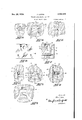
- Fig. 1 is a front elevational view of a burner and/or heater housing which may be made in the practice of my invention
- Fig. 2 is a fragmentary elevational view taken from the plane 2 of Fig. 1;
- Fig. 3 is a top plan view of the housing of Fig. 1;
- Fig. 4 is a bottom plan view of the housing of Fig. 1 with the parts in open position;
- Fig. 5 is a longitudinal sectional view of a molding flask illustrating the apparatus and method of molding the housing of Fig. 1;
- Fig. 6 is a view taken from the plane 6-6 of Fig. 5;
- Fig. 7 is a fragmentary view-taken from the plane 1 of Fig. 5 and with a core element of Fig. 5 omitted;
- Fig. 8 is a view taken from the plane 8 of Fig. 7
- Fig. 9 is a plan view and Fig. 10 is an elevational view of a core device which I may employ;
- Fig. 11 is a View taken from the plane I i of Fig. 5 but illustrating the mold of Fig. 5 after the metal has been poured;
- Fig. 12 is a View taken from the plane 12 of Fig. 11;
- Fig. 13 is a view taken from the plane l3 of 5 Fig. 11;
- Fig. 14 is a view similar in general to a part of Fig. 6 but illustrating the pattern which I may employ in the mold before the withdrawal of the pattern
- Fig. 15 is a view taken from the plane 15 of Fig. 14;
- Fig. 16 is a view taken from the plane l6 of Fig. 14;
- Fig. 17 is a cross-sectional view of a core box which I may employ;
- Fig. 18 is a view taken from the plane [8 of Fig. 17;
- Figs. 19 and 20 are, respectively, plane and front elevational views of a core element which I may employ similar in general, except as to dimension, to the core element of Figs. 9 and 10;
- Fig. 21 is a fragmentary view similar to a part of Fig. 1 but illustrating a modification
- Fig. 22 is a view similar to Fig. 21 illustrating another modification
- Fig. 23 is a view similar to Fig. 12 illustrating a step of process in the production of the forms of Fig. 21 or Fig. 22;
- a hot water heater and/or burner housing of the general form and construction of those commonly in use and comprising generally two semi-cylindrical shells I and 2 hinged together by longitudinally spaced hinges 3 and 4.
- the parts I and 2 and the hinges 3 and 4 connecting the parts are formed complete and hinged together by a molding apparatus and method of my invention to be described.
- the shell I has a thin wall 5 of hollow semicylindrical form having on the upper end thereof an inwardly directed flange 6 and the shell 2 has a similar wall I and on the upper end an inwardly directed flange 8.
- the flanges 6 and 8 are disposed substantially coplanar when the shells are in their assembled relationship illustrated to provide an upper flat end to the housing whereby it may be attached to or have mounted thereon a suitable cover for receiving a pipe or stack.
- the flange 8 is provided with a plurality such as two open ended slots 99 extending generally parallel to each other and to provide material to support the same, the flange 8 is thickened horizontally in the neighborhood of the slots as at it and II.
- the opposite or lower ends of the shells I and 2 are provided respectively with inwardly directed substantially coplanar flanges l2 and I3.
- the flange i3 is provided with a plurality such as three inwardly open slots l4, l5 and IS, the flange being thickened or widened at I7, I8 and I9 to provide material for the slots.
- the shell i is provided with a pair of longitudinally spaced arms 28 and 2
- the arms are thus disposed in pairs 2ll22 and 2I-23, the arms of each pair being longitudinally spaced.
- Each of the pairs of arms is provided with a pair of, confronting faces 24-25 spaced apart longitudinally and balls 26 and 21 are seated in ball sockets 28-28 in the faces 24 and respectively, the sockets being of spherical segmental form, of exactly the same radius as the balls 26-21.
- the arms and balls thus described constitute hinges longitudinally spaced on the shells which perform several functions: that of connecting the two shells together to prevent separation either longitudinally or laterally, to provide hinges whereby the two shells may be moved with a hinging movement relative to each other on a common axis through the center of the balls 25 and 21, and in a manner to be more fully de scribed, provide means whereby the two shells l and 2 may be, by a single molten metal casting operation, formed and assembled in hinged relation; and inasmuch as the hinge construction described permits of molding or casting the two shells in their hingedly open relation as illustrated in Fig. 4, the construction permits of casting the slots 9-ii, 24, I5 and I6 by the same operation.
- the slots 99 on the top of the assembled housing and the slots I4, I5 and i6 on the bottom hereof provide attachment means whereby at the top of the device a suitable cover may be attached to cover the housing and the heater therewithin and to conduct burnt gases to a smoke pipe and whereby at the bottom of the device it may be secured to the burner proper or a base thereof.
- the flanges 6 and 8 are preferably disposed in a plane at right angles to the axis of the shells as are also the flanges I2 and I3 on the bottom of the housing.
- bolts may be placed therein as 5 indicated at 29 in Fig. 3, the heads of the bolts, 30, overlapping the slots and the bolts may project upwardly and be engaged with the cover to be secured thereto.
- bolts in the slots I4, I5 and It may secure the housing 1 to the burner base.
- the outer surfaces of the shells 20 may be cast with ornamentation thereon such as that clearly shown in Fig. 1.
- the hinge construction thus provided may be wholly without lost motion, require no assembling time or labor in the production thereof, and, due to the chilling of the metal in the arms where it contacts with the balls, the relatively moving 30 parts of the bearing will have the maximum of life and durability without wear.
- FIG. 4 A pattern is first made of the housing exactly of the same form and configuration in every respect as the finished shells to be and in the pattern the shells are disposed in their hingedly open position illustrated in Fig. 4.
- Fig. 4 may be considered an illustration of the pattern with the exception of the parts at the hinge itself, which will presently be described; and thus the form and configuration of the pattern throughout will now be clear from Fig. 4 taken in connection with the other figures of the finished housing.
- the hinge parts of the pattern are formed as illustrated in Figs. 14 to 16, Fig. 14 being a View of that part of the pattern correspond- 5 ing to the hinge parts of the finished structure of Fig. 4 and Figs. 15 and 16 being views of these parts taken from the planes l5 and I6 of Fig. 14.
- the hinge, portion of the pattern therefore, is seen to comprise arm portions 23' and 2I corresponding generally in form to the finished arms to be, 23 and 2 I, integrally joined by a core print portion 32 comprising a central web portion 33 and on the lower portion thereof, extensions 34 and 35 integrally joined with the arm portions 23' and 2
- the mold of Fig, 5 comprises the usual cope 3E and drag 31 and sand 38 and 39 therein and Fig.
- FIG. 5 illustrates the mold in the condition thereof 5 after the pattern above described has been rammed and withdrawn and a core element 59 (to be described) has been inserted.
- the mold cavity left in the mold will have the same shape as the pattern above described and the View, Fig. 5, being taken on a central plane.
- the cavity portion 40 is that which is left by the hinge portion of the pattern, illustrated in Figs. 14, 15 and 16. This hinge portion of the mold is also illustrated in Fig. '7, without the core element 50.
- a core element 50 is next made, illustrated in Figs. 9 and 10, and comprises a relatively thin web portion 4
- a steel ball 46 is lodged in the web portion 4
- the core element 56 of Figs. 9 and 10 is then placed in the hinge portion of the mold cavity and appears as illustrated in Figs. 5 and 6; and as will now be apparent, the ball 46 is supported in the central portion of the hinge cavity and the hinge cavity is divided by the web portion 4
- the metal is poured therein through the usual gate (not shown) and fills the mold cavity surrounding the core element therein and when the metal has solidified, the form thereof except at the ends will be clearly understood from the foregoing.
- the solidified metal in the sand mold and adjacent the core element 56 appears as illustrated in Figs. 11, 12 and 13; portions of the two shells are illustrated at and 2 and a hinge arm 23 and a hinge arm 2
- the surfaces of the core element 58 and of the core print portions 34 and 35 permit a parting line between the two halves of the mold to be made at 55 along the lower surface portion 55' of the core element 56 and thus the core element may be all in one piece and set in the drag portion of the mold; and this permits the integral construction of the core element and its embraced hinge ball 46, a construction which would be inferior and inconvenient if the core element holding the ball were in a plurality of pieces, one or more to be placed in each of the halves of the mold.
- the molding of the two shells in their hingedly open position permits the draft of the pattern including that of the core element 50 to fall in opposite directions on opposite sides of the pattern whereby no coring other than that to support the ball 46 is required.
- the ball is disposed wholly in one half, preferably the drag of the mold, and thus a parting line at the ball with the usual disadvantageous fins is avoided.
- the ball 46 is preferably a hardened steel ball and thus, as is well understood, the metal, particularly if it is cast iron, upon flowing around the ball on each side thereof, is chilled thereby.
- the socket formed around the ball has a chilled and thus hardened surface with the ad'- vantages set forth hereinbefore.
- attachment means at both ends of the complete housing in the form of slots 99 and
- a suitable core box for forming the core element 50 is illustrated in Figs. 17 and 18 and com- 5 prises two halves 60 and 6
- the ball 46 may be placed in the recesses 65 and the two parts of the box placed together and then the cavity therein rammed with the core sand or other suit- 15 able material to form the core, the box positioning the ball in the core and forming itintegral therewith.
- the upper portion thereof is of smaller di- 20 ameter than the lower portion. Therefore, if the arms 23 and 22 are of the same length as the arms 2
- Fig. 21 I have illustrated a modification in which the bearing element 66 molded in position with respect to the pair of adjacent arms 81 and 68 is not a sphere.
- the bearing element 66 is provided having a generally spherical portion 69 connected to a base portion it) by an intermediate neck portion 1
- the metal of the arm 61 is cast around the base portion HI and around a part of the neck por- 40 tion H to rigidly grip the base portion :0 in the arm 61, and the arm 68 is cast with a recess 3 partly embracing the spherical portion 69.
- hing-e elements 66 are, as just described, provided at the upper and lower end 45 portions of the doors and in each case between pairs of arms or h nge portions, 6'
- the bases 10 are cast in the axially outermost arms or bearing portions 61 and 15, and the recesses 13 are cast in the innermost 50 arms 68 and 14.
- 3 thus face concavely in opposite directions longitudinally whereby the doors are prevented from shifting relatively longitudinally and relatively laterally.
- the relative movements occurring during the 55 hinging action occurs between the arms-68 and I4 and the element 66.
- Fig. 22 a construction similar to that of Fig. 21 is shown except that the bases it of the bearing elements are cast rigidly in 60 the innermost arms 16 and TI and the recesses in the outermost arms 78 and 19.
- face concavely toward each other but as in the case of Fig. 21, the spherical portions of the bearing element, in the 65 recesses, prevent lateral as well as longitudinal displacement of the doors as well as providing hinging surfaces.
- Fig. 23 is illustrated one of the steps of molding the bearing element 66 in the arms .or 70 bearing portions of the door, for example the portions 6'1 and 68.
- This view being similar to Fig. 12 which has been fully described herein, it is believed that with this brief showing it will be understood.
- a core element similar to '15 the core element illustrated in Figs. 9 and 10 is provided but instead of supporting therein a spherical ball, supports therein the element 66 with the spherical portion 69 projecting from one side of the core element and the base 10 projecting from the other side.
- Fig. 24 is illustrated still another modificat'on in which the spherical recesses 83 and 84 face in the same longitudinal direction and the recess 83 is in the arm 85 of one of the doors and the recess 8% is in an arm 86 of the opposite door.
- the recesses are in arms on the same door.
- a heater housing comprising a pair of cast metal elongated concave-convex shell elements having a hinge connection on a common axis, the hinge connection comprising spaced pairs of arms cast integral with the shell elements, the arms of each pair projecting laterally from one of the shells respectively, and the arms on one shell disposed between the arms on the other shell, and each arm on one shell disposed adjacent to an arm on the other shell and the adjacent arms provided with confronting recesses, and a metal ball in each pair of confronting recesses upon which the pair of arms may have hinging movement.
- a heater housing comprising a pair of cast metal elongate-d concavo-convex shell elements having hinging connection with each other on a common longitudinal axis, the hinge connection comprising longitudinally spaced arms cast integral with each shell element disposed in adjacent pairs, one arm of each pair being on different ones of the elements, confronting recesses in each pair of arms, a steel ball in each pair of arms, and the recesses on one shell being disposed longitudinally between the arms of the other shell whereby relative longitudinal displacement of the shells is prevented.
- a heater housing comprising a pair of cast metal elongated concavo-convex shell elements having a hinging connection with each other on a common longitudinal axis, the hinging connection comprising a plurality of arms extending laterally from the shells in adjacent pairs, the arms of each pair cast integral with difierent ones of the shells, and the arms on one shell being between the arms on the other shell, confronting recesses in the pairs of arms, steel balls in each pair of recesses, the shells having transversely extending end flanges provided each with a plurality of parallel open ended slots for receiving the bodies of attaching bolts inserted thereinto longitudinally of the slots and laterally of the bolts.
- a heater housing comprising a pair of cast metal elongated concave-convex shell elements having a hinging connection with each other on a common longitudinal axis, the hinging connection comprising a plurality of arms extending laterally from the shells in adjacent pairs, the arms of each pair cast integral with different ones of the shells, and the arms on one shell being between the arms on the other shell, confronting recesses in the pairs of arms, steel balls in each pair of recesses, a shell having a transverse ly extending end flange provided with a plurality of parallel spaced open ended slots for receiving the bodies of attaching bolts inserted thereinto longitudinally of the slots and laterally of the bolts.
- a pair of cast metal elements having hinging connection with each other on a. common longitudinal axis externally of the elements, the hinging connection comprising a plurality of arms extending laterally from the elements in adjacent pairs, the arms of each pair being cast integrally with difierent ones of the elements, and the arms on one element being between the arms on the other element, confronting recesses in the pairs of arms, and steel balls in each pair of recesses.
- a pair of cast metal elements having hinging connection with each other on a hinging axis, the hinging connection comprising a plurality of pairs of hinging portions, the hinging portions of each pair being cast integrally with different ones of the elements, a part-spherical recess in one hinging portion of each pair concavely confronting the other hinging portion of the pair, a metal hinging element having a part-spherical surface portion in the recess and having a portion partly embedded in the cast metal of the other hinging portion, the recesses and spherical portions of the elements may move with a hinging movement.
- a pair of cast metal elements having hinging connection with each other on a common axis disposed laterally of the elements, the hinging connection comprising a. plurality of pairs of cooperating hinging 4o portions, the two portions of each pair being on a different one of the elements, and the portions on one element being between the portions on the other element, each pair of said hinging portions being provided with parti-spherical recesses confrontingly disposed, a ball for each hinging pair disposed in the confronting recesses, both elements and their associated hinging portions being cast integral in a single casting operation with the balls maintained in assembled relation by a core element, the balls affording the hinging movement between the elements and preventing longitudinal and lateral displacement.
- the hinging connection comprising means providing a plurality of shoulder portions extending laterally from the elements in adjacent pairs, the shoulder portions of each pair being cast integrally with different ones of the elements, and the shoulder portions on one element being between the shoulder portions on the other element, confronting recesses in the pairs of shoulder portions, and a metal ball in each pair of recesses.
- a pair of cast metal elements having hinging connection with each other on a hinging axis, the hinging connection comprising a plurality of pairs of hinging portions, the hinging portions of each pair being cast integrally with different ones of the elements,
- a metal hinging element having. a convex surface portion projecting into the recess and having a portion partly embedded in the cast metal of the other hinging portion, the recesses and convex portions of the hinging elements being disposed to prevent longitudinal and lateral displacement of the cast metal elements and providing relatively movable surfaces upon which the two cast metal elements may move with a hinging movement.
- a pair of cast metal elements having hinging connection with each other on a common axis, the hinging connection comprising means providing a plurality of shoulder portions extending laterally from the elements in adjacent pairs, the shoulder portions of each pair being cast integrally with different ones of the elements, and the shoulder portions on one element being between the shoulder portions on the other element, confronting recesses in the pairs of shoulder portions, and a metal bearing element having opposite convex portions in each pair of recesses.
Landscapes
- Engineering & Computer Science (AREA)
- Mechanical Engineering (AREA)
- Physics & Mathematics (AREA)
- Thermal Sciences (AREA)
- Chemical & Material Sciences (AREA)
- Combustion & Propulsion (AREA)
- General Engineering & Computer Science (AREA)
- Molds, Cores, And Manufacturing Methods Thereof (AREA)
Description
Nov. 26, 1935. J. LUTON 2,022,472
MOLDED ARTI CULATED ART I CLE Filed May 8, 1955 4 Sheets-Sheet 1 INVENTOR.
Jo/i n L u for].
ATTORNEY.
Nov. 26, 1935. J. LUTON 2,022,472
MOLDED ARTICULATED ARTICLE Filed May 8, 1953 4 Sheets-Sheet 5 INVENTOR.
J/m Z 2150 n.
ATTORNEY.
Nov. 26,1935. J. LUTON 2,022,472
MOLDED ARTICULATED ARTICLE 7 Filed May 8, 1933 4 Sheets-Sheet 4 INVENTOR.
"81- JJ/m Luton 86- BY a a M 11D 24 ATTORNEY.
Patented Nov. 26, 1935 UNITED STATES PATENT OFFICE MOLDED ARTICULATED ARTICLE John Luton, Cleveland Heights, Ohio, assignor to The Consolidated Iron-Steel Mfg. Company of 1932, Cleveland, Ohio, a corporation of Ohio Application May 8, 1933, Serial No. 669,836
10 Claims.
This invention relates to articles molded from molten metal.
More particularly, the invention relates to articles molded by a single metal casting operation,
and comprising two or more separate parts hav- :in as having particular application to the housthe heating coils and at the lower end enclosing the burner which is usually a gas burner. The cylinder is in two parts hinged together on a vertical axis, one part being stationary and the other movable as a door to give access to the burner and coils. The two halves of the housing are furthermore provided with lugs or like devices at the upper and lower ends thereof for attachment to the burner at the lower end and attachment to a suitable cover leading to a pipe or stack to convey away burnt gases.
In common practice, the two halves of such cylinders are made separately and joined together by a hinge construction and the lugs or like devices thereon for the purposes mentioned are drilled with holes for the reception of securing bolts. 7 Such separate halves have been made as castings by pouring molten metal in sand molds. 7
It is an object of this invention to provide a pair of hollow parti-cylindrical elements suitable to compose a burner housing of the class referred to which may, by a single molten metal casting operation, be formed complete with the hinge connection therebetween, and the lugs and other essential parts.
Another object is to provide an improved core device for use in sand molds for molding two parts hinged together at a single molding operation.
Another object is to provide an improved burn er or heater housing of the class referred to. 7
Another object is to provide an improved hinge construction which may be employed to join two cast articles by a single molten metal casting operation.
ther objects will be apparent to those skilled in the art to which my invention appertains.
My invention is fully disclosed in the following description taken in connection with the accompanying drawings, in which:
Fig. 1 is a front elevational view of a burner and/or heater housing which may be made in the practice of my invention;
Fig. 2 is a fragmentary elevational view taken from the plane 2 of Fig. 1; Fig. 3 is a top plan view of the housing of Fig. 1; Fig. 4 is a bottom plan view of the housing of Fig. 1 with the parts in open position;
Fig. 5 is a longitudinal sectional view of a molding flask illustrating the apparatus and method of molding the housing of Fig. 1;
Fig. 6 is a view taken from the plane 6-6 of Fig. 5;
Fig. 7 is a fragmentary view-taken from the plane 1 of Fig. 5 and with a core element of Fig. 5 omitted;
Fig. 8 is a view taken from the plane 8 of Fig. 7
Fig. 9 is a plan view and Fig. 10 is an elevational view of a core device which I may employ;
Fig. 11 is a View taken from the plane I i of Fig. 5 but illustrating the mold of Fig. 5 after the metal has been poured;
Fig. 12 is a View taken from the plane 12 of Fig. 11;
Fig. 13 is a view taken from the plane l3 of 5 Fig. 11;
Fig. 14 is a view similar in general to a part of Fig. 6 but illustrating the pattern which I may employ in the mold before the withdrawal of the pattern Fig. 15 is a view taken from the plane 15 of Fig. 14;
Fig. 16 is a view taken from the plane l6 of Fig. 14;
Fig. 17 is a cross-sectional view of a core box which I may employ;
Fig. 18 is a view taken from the plane [8 of Fig. 17;
Figs. 19 and 20 are, respectively, plane and front elevational views of a core element which I may employ similar in general, except as to dimension, to the core element of Figs. 9 and 10;
Fig. 21 is a fragmentary view similar to a part of Fig. 1 but illustrating a modification;
Fig. 22 is a view similar to Fig. 21 illustrating another modification;
Fig. 23 is a view similar to Fig. 12 illustrating a step of process in the production of the forms of Fig. 21 or Fig. 22;
which maybe produced by the practice of my invention, namely a hot water heater and/or burner housing of the general form and construction of those commonly in use and comprising generally two semi-cylindrical shells I and 2 hinged together by longitudinally spaced hinges 3 and 4.
The parts I and 2 and the hinges 3 and 4 connecting the parts are formed complete and hinged together by a molding apparatus and method of my invention to be described.
The shell I has a thin wall 5 of hollow semicylindrical form having on the upper end thereof an inwardly directed flange 6 and the shell 2 has a similar wall I and on the upper end an inwardly directed flange 8. The flanges 6 and 8 are disposed substantially coplanar when the shells are in their assembled relationship illustrated to provide an upper flat end to the housing whereby it may be attached to or have mounted thereon a suitable cover for receiving a pipe or stack. To this end, the flange 8 is provided with a plurality such as two open ended slots 99 extending generally parallel to each other and to provide material to support the same, the flange 8 is thickened horizontally in the neighborhood of the slots as at it and II.
The opposite or lower ends of the shells I and 2 are provided respectively with inwardly directed substantially coplanar flanges l2 and I3. The flange i3 is provided with a plurality such as three inwardly open slots l4, l5 and IS, the flange being thickened or widened at I7, I8 and I9 to provide material for the slots.
The shell i is provided with a pair of longitudinally spaced arms 28 and 2| extending generally outwardly radially therefrom; and the shell 2 is provided with a corresponding pair of arms 22 and 23 longitudinally spaced apart farther than the arms and 2I. The arms are thus disposed in pairs 2ll22 and 2I-23, the arms of each pair being longitudinally spaced. Each of the pairs of arms is provided with a pair of, confronting faces 24-25 spaced apart longitudinally and balls 26 and 21 are seated in ball sockets 28-28 in the faces 24 and respectively, the sockets being of spherical segmental form, of exactly the same radius as the balls 26-21.
The arms and balls thus described constitute hinges longitudinally spaced on the shells which perform several functions: that of connecting the two shells together to prevent separation either longitudinally or laterally, to provide hinges whereby the two shells may be moved with a hinging movement relative to each other on a common axis through the center of the balls 25 and 21, and in a manner to be more fully de scribed, provide means whereby the two shells l and 2 may be, by a single molten metal casting operation, formed and assembled in hinged relation; and inasmuch as the hinge construction described permits of molding or casting the two shells in their hingedly open relation as illustrated in Fig. 4, the construction permits of casting the slots 9-ii, 24, I5 and I6 by the same operation.
As will be understood by those skilled in the art, the slots 99 on the top of the assembled housing and the slots I4, I5 and i6 on the bottom hereof, provide attachment means whereby at the top of the device a suitable cover may be attached to cover the housing and the heater therewithin and to conduct burnt gases to a smoke pipe and whereby at the bottom of the device it may be secured to the burner proper or a base thereof. To this end, the flanges 6 and 8 are preferably disposed in a plane at right angles to the axis of the shells as are also the flanges I2 and I3 on the bottom of the housing.
To utilize the slots 9, I4, I5 and I6 for the purpose mentioned, bolts may be placed therein as 5 indicated at 29 in Fig. 3, the heads of the bolts, 30, overlapping the slots and the bolts may project upwardly and be engaged with the cover to be secured thereto. In a similar manner, bolts in the slots I4, I5 and It may secure the housing 1 to the burner base. Inasmuch as the cover and base are well known in this art in connection with other constructions of heater housing, it is believed unnecessary to illustrate or describe the cover or base or the means of attaching the hous- 15 ing thereto.
Furthermore, inasmuch as the shells and their hinges may be cast at one operation with the shells in their hingedly open position as illustrated in Fig. 4, the outer surfaces of the shells 20 may be cast with ornamentation thereon such as that clearly shown in Fig. 1.
Furthermore, inasmuch as the arms 2D22 and 2I23 are cast around the balls 26 and 21 respectively in a manner to be more fully described, 25 the hinge construction thus provided may be wholly without lost motion, require no assembling time or labor in the production thereof, and, due to the chilling of the metal in the arms where it contacts with the balls, the relatively moving 30 parts of the bearing will have the maximum of life and durability without wear.
The molding and casting operation by which the housing above described may be made by a single molding operation will now be described. A pattern is first made of the housing exactly of the same form and configuration in every respect as the finished shells to be and in the pattern the shells are disposed in their hingedly open position illustrated in Fig. 4. In other words, Fig. 4 may be considered an illustration of the pattern with the exception of the parts at the hinge itself, which will presently be described; and thus the form and configuration of the pattern throughout will now be clear from Fig. 4 taken in connection with the other figures of the finished housing.
The hinge parts of the pattern, however, are formed as illustrated in Figs. 14 to 16, Fig. 14 being a View of that part of the pattern correspond- 5 ing to the hinge parts of the finished structure of Fig. 4 and Figs. 15 and 16 being views of these parts taken from the planes l5 and I6 of Fig. 14. The hinge, portion of the pattern, therefore, is seen to comprise arm portions 23' and 2I corresponding generally in form to the finished arms to be, 23 and 2 I, integrally joined by a core print portion 32 comprising a central web portion 33 and on the lower portion thereof, extensions 34 and 35 integrally joined with the arm portions 23' and 2| respectively. A mold illustrated in Fig.
5 is then made from the pattern above described.
The mold of Fig, 5 comprises the usual cope 3E and drag 31 and sand 38 and 39 therein and Fig.
5 illustrates the mold in the condition thereof 5 after the pattern above described has been rammed and withdrawn and a core element 59 (to be described) has been inserted. The mold cavity left in the mold will have the same shape as the pattern above described and the View, Fig. 5, being taken on a central plane. The cavity portion 40 is that which is left by the hinge portion of the pattern, illustrated in Figs. 14, 15 and 16. This hinge portion of the mold is also illustrated in Fig. '7, without the core element 50.
A core element 50 is next made, illustrated in Figs. 9 and 10, and comprises a relatively thin web portion 4| and laterally extending projections 44 and 45, the shape of these parts being substantially the same and of the same size as the portions 33, 34 and 35 (see Figs. 14 to 16). A steel ball 46 is lodged in the web portion 4| and the core element thus provided is preferably made from sand containing a binder, formed in a core box, and the ball 46 is molded directly in the core element; so that when the element is finished, the ball is integral therewith and projects substantially equal distances from the opposite sides of the web portion 4| as shown in the drawings.
The core element 56 of Figs. 9 and 10 is then placed in the hinge portion of the mold cavity and appears as illustrated in Figs. 5 and 6; and as will now be apparent, the ball 46 is supported in the central portion of the hinge cavity and the hinge cavity is divided by the web portion 4| of the core element.
After the mold has thus been made, the metal is poured therein through the usual gate (not shown) and fills the mold cavity surrounding the core element therein and when the metal has solidified, the form thereof except at the ends will be clearly understood from the foregoing. At the hinge, the solidified metal in the sand mold and adjacent the core element 56 appears as illustrated in Figs. 11, 12 and 13; portions of the two shells are illustrated at and 2 and a hinge arm 23 and a hinge arm 2| embrace therebetween the ball 46 and the web portion 4| of the core element, the projections 44 and 45 defining curved portions of the ends of the arms.
Upon removing the solidified metal from the mold and breaking out the core element 56, the hinge construction hereinbefore described is found to be completed.
The surfaces of the core element 58 and of the core print portions 34 and 35 permit a parting line between the two halves of the mold to be made at 55 along the lower surface portion 55' of the core element 56 and thus the core element may be all in one piece and set in the drag portion of the mold; and this permits the integral construction of the core element and its embraced hinge ball 46, a construction which would be inferior and inconvenient if the core element holding the ball were in a plurality of pieces, one or more to be placed in each of the halves of the mold.
Furthermore, the molding of the two shells in their hingedly open position permits the draft of the pattern including that of the core element 50 to fall in opposite directions on opposite sides of the pattern whereby no coring other than that to support the ball 46 is required.
In accordance with the foregoing it will be observed that the ball is disposed wholly in one half, preferably the drag of the mold, and thus a parting line at the ball with the usual disadvantageous fins is avoided.
The ball 46 is preferably a hardened steel ball and thus, as is well understood, the metal, particularly if it is cast iron, upon flowing around the ball on each side thereof, is chilled thereby. Thus the socket formed around the ball has a chilled and thus hardened surface with the ad'- vantages set forth hereinbefore.
By providing attachment means at both ends of the complete housing in the form of slots 99 and |4, I5 and i6, and by disposing the longitudi nal direction of these slots at a right angle to the parting line of the pattern, such attachment means may be molded without cores and without machining operations performed on the solidified metal as has been necessary heretofore.
A suitable core box for forming the core element 50 is illustrated in Figs. 17 and 18 and com- 5 prises two halves 60 and 6| having the usual dowel pins 62 in one half and recess 63 in the other half, the two halves having confronting recesses indicated generally at 6464 of the contour and shape and size of the core to be made, each part 10 having therein concavely confronting recesses 65--65 of sphere segment form. The ball 46 may be placed in the recesses 65 and the two parts of the box placed together and then the cavity therein rammed with the core sand or other suit- 15 able material to form the core, the box positioning the ball in the core and forming itintegral therewith.
In the particular form of heater illustrated in Fig. l, the upper portion thereof is of smaller di- 20 ameter than the lower portion. Therefore, if the arms 23 and 22 are of the same length as the arms 2| and 23, the hinging axis will not be parallel to the axis of the doors and when the half I is opened as a door, it will tend always to swing 25 shut. If it be desired to have the hinging axis parallel with the axis of the heater housing as a whole, the arms 20 and 22 may be made longer and in this connection I find it desirable to employ 'a larger core element such as illustrated in Figs. 19 and 20.
In Fig. 21 I have illustrated a modification in which the bearing element 66 molded in position with respect to the pair of adjacent arms 81 and 68 is not a sphere. In this form, the bearing element 66 is provided having a generally spherical portion 69 connected to a base portion it) by an intermediate neck portion 1|.
The metal of the arm 61 is cast around the base portion HI and around a part of the neck por- 40 tion H to rigidly grip the base portion :0 in the arm 61, and the arm 68 is cast with a recess 3 partly embracing the spherical portion 69. As shown in Fig. 21, hing-e elements 66 are, as just described, provided at the upper and lower end 45 portions of the doors and in each case between pairs of arms or h nge portions, 6'|68 and 14-15. The bases 10 are cast in the axially outermost arms or bearing portions 61 and 15, and the recesses 13 are cast in the innermost 50 arms 68 and 14. The recesses '|3'|3 thus face concavely in opposite directions longitudinally whereby the doors are prevented from shifting relatively longitudinally and relatively laterally. The relative movements occurring during the 55 hinging action occurs between the arms-68 and I4 and the element 66. I
In the form of Fig. 22, a construction similar to that of Fig. 21 is shown except that the bases it of the bearing elements are cast rigidly in 60 the innermost arms 16 and TI and the recesses in the outermost arms 78 and 19. In this case the recesses 86 and 8| face concavely toward each other but as in the case of Fig. 21, the spherical portions of the bearing element, in the 65 recesses, prevent lateral as well as longitudinal displacement of the doors as well as providing hinging surfaces.
In Fig. 23 is illustrated one of the steps of molding the bearing element 66 in the arms .or 70 bearing portions of the door, for example the portions 6'1 and 68. This view being similar to Fig. 12 which has been fully described herein, it is believed that with this brief showing it will be understood. A core element similar to '15 the core element illustrated in Figs. 9 and 10 is provided but instead of supporting therein a spherical ball, supports therein the element 66 with the spherical portion 69 projecting from one side of the core element and the base 10 projecting from the other side.
In Fig. 24 is illustrated still another modificat'on in which the spherical recesses 83 and 84 face in the same longitudinal direction and the recess 83 is in the arm 85 of one of the doors and the recess 8% is in an arm 86 of the opposite door. In the forms of Figs. 21 and 22, the recesses are in arms on the same door.
Other and various combinations of the recesses and spherical hinge elements may be made embodying my invention.
My invention is not limited in all respects to the exact details shown and described inasmuch as, without departing from the spirit of my invention or sacrificing its advantages, numerous changes and modifications may be made.
I claim:
1. A heater housing comprising a pair of cast metal elongated concave-convex shell elements having a hinge connection on a common axis, the hinge connection comprising spaced pairs of arms cast integral with the shell elements, the arms of each pair projecting laterally from one of the shells respectively, and the arms on one shell disposed between the arms on the other shell, and each arm on one shell disposed adjacent to an arm on the other shell and the adjacent arms provided with confronting recesses, and a metal ball in each pair of confronting recesses upon which the pair of arms may have hinging movement.
2. A heater housing comprising a pair of cast metal elongate-d concavo-convex shell elements having hinging connection with each other on a common longitudinal axis, the hinge connection comprising longitudinally spaced arms cast integral with each shell element disposed in adjacent pairs, one arm of each pair being on different ones of the elements, confronting recesses in each pair of arms, a steel ball in each pair of arms, and the recesses on one shell being disposed longitudinally between the arms of the other shell whereby relative longitudinal displacement of the shells is prevented.
3. A heater housing comprising a pair of cast metal elongated concavo-convex shell elements having a hinging connection with each other on a common longitudinal axis, the hinging connection comprising a plurality of arms extending laterally from the shells in adjacent pairs, the arms of each pair cast integral with difierent ones of the shells, and the arms on one shell being between the arms on the other shell, confronting recesses in the pairs of arms, steel balls in each pair of recesses, the shells having transversely extending end flanges provided each with a plurality of parallel open ended slots for receiving the bodies of attaching bolts inserted thereinto longitudinally of the slots and laterally of the bolts.
4. A heater housing comprising a pair of cast metal elongated concave-convex shell elements having a hinging connection with each other on a common longitudinal axis, the hinging connection comprising a plurality of arms extending laterally from the shells in adjacent pairs, the arms of each pair cast integral with different ones of the shells, and the arms on one shell being between the arms on the other shell, confronting recesses in the pairs of arms, steel balls in each pair of recesses, a shell having a transverse ly extending end flange provided with a plurality of parallel spaced open ended slots for receiving the bodies of attaching bolts inserted thereinto longitudinally of the slots and laterally of the bolts.
5. As an article of manufacture, a pair of cast metal elements having hinging connection with each other on a. common longitudinal axis externally of the elements, the hinging connection comprising a plurality of arms extending laterally from the elements in adjacent pairs, the arms of each pair being cast integrally with difierent ones of the elements, and the arms on one element being between the arms on the other element, confronting recesses in the pairs of arms, and steel balls in each pair of recesses.
6. As an article of manufacture, a pair of cast metal elements having hinging connection with each other on a hinging axis, the hinging connection comprising a plurality of pairs of hinging portions, the hinging portions of each pair being cast integrally with different ones of the elements, a part-spherical recess in one hinging portion of each pair concavely confronting the other hinging portion of the pair, a metal hinging element having a part-spherical surface portion in the recess and having a portion partly embedded in the cast metal of the other hinging portion, the recesses and spherical portions of the elements may move with a hinging movement.
7. As an article of manufacture, a pair of cast metal elements having hinging connection with each other on a common axis disposed laterally of the elements, the hinging connection comprising a. plurality of pairs of cooperating hinging 4o portions, the two portions of each pair being on a different one of the elements, and the portions on one element being between the portions on the other element, each pair of said hinging portions being provided with parti-spherical recesses confrontingly disposed, a ball for each hinging pair disposed in the confronting recesses, both elements and their associated hinging portions being cast integral in a single casting operation with the balls maintained in assembled relation by a core element, the balls affording the hinging movement between the elements and preventing longitudinal and lateral displacement.
8. As an article of manufacture, a pair of cast metal elements having hinging connection with 55,-
each other on a common axis, the hinging connection comprising means providing a plurality of shoulder portions extending laterally from the elements in adjacent pairs, the shoulder portions of each pair being cast integrally with different ones of the elements, and the shoulder portions on one element being between the shoulder portions on the other element, confronting recesses in the pairs of shoulder portions, and a metal ball in each pair of recesses.
9. As an article of manufacture, a pair of cast metal elements having hinging connection with each other on a hinging axis, the hinging connection comprising a plurality of pairs of hinging portions, the hinging portions of each pair being cast integrally with different ones of the elements,
a concave recess in one hinging portion of each pair concavely confronting the other hinging portion of the pair, a metal hinging element having. a convex surface portion projecting into the recess and having a portion partly embedded in the cast metal of the other hinging portion, the recesses and convex portions of the hinging elements being disposed to prevent longitudinal and lateral displacement of the cast metal elements and providing relatively movable surfaces upon which the two cast metal elements may move with a hinging movement.
10. As an article of manufacture, a pair of cast metal elements having hinging connection with each other on a common axis, the hinging connection comprising means providing a plurality of shoulder portions extending laterally from the elements in adjacent pairs, the shoulder portions of each pair being cast integrally with different ones of the elements, and the shoulder portions on one element being between the shoulder portions on the other element, confronting recesses in the pairs of shoulder portions, and a metal bearing element having opposite convex portions in each pair of recesses.
JOHN LU'ION.
Priority Applications (1)
| Application Number | Priority Date | Filing Date | Title |
|---|---|---|---|
| US669836A US2022472A (en) | 1933-05-08 | 1933-05-08 | Molded articulated article |
Applications Claiming Priority (1)
| Application Number | Priority Date | Filing Date | Title |
|---|---|---|---|
| US669836A US2022472A (en) | 1933-05-08 | 1933-05-08 | Molded articulated article |
Publications (1)
| Publication Number | Publication Date |
|---|---|
| US2022472A true US2022472A (en) | 1935-11-26 |
Family
ID=24687938
Family Applications (1)
| Application Number | Title | Priority Date | Filing Date |
|---|---|---|---|
| US669836A Expired - Lifetime US2022472A (en) | 1933-05-08 | 1933-05-08 | Molded articulated article |
Country Status (1)
| Country | Link |
|---|---|
| US (1) | US2022472A (en) |
-
1933
- 1933-05-08 US US669836A patent/US2022472A/en not_active Expired - Lifetime
Similar Documents
| Publication | Publication Date | Title |
|---|---|---|
| CA2573306C (en) | Railway car coupler knuckle having improved bearing surface | |
| US4143701A (en) | Core assembly in a coupler for a railway vehicle | |
| WO2013096161A2 (en) | Subsurface chills to improve railcar knuckle formation | |
| US3756309A (en) | Composite foundry core | |
| US2022472A (en) | Molded articulated article | |
| CN110586865B (en) | Universal casting method for small and medium-sized steel castings | |
| US2066658A (en) | Method of making valves | |
| US4938802A (en) | Reusable ceramic mold | |
| US3254849A (en) | Cast hollow balls | |
| US2004810A (en) | Method of making hinges | |
| US3077014A (en) | Molding machine and process | |
| US3082496A (en) | Continuous casting ingot mold | |
| US1867862A (en) | Piston-sand core | |
| US2239381A (en) | Mold for making hollow cast metal valves | |
| JPS5942584B2 (en) | Casting method for engine crankshafts | |
| US1645729A (en) | Mold | |
| US3263288A (en) | Method of casting cored objects | |
| CN115805299A (en) | Vertical casting system and casting method for railway vehicle buffer box body | |
| US1449085A (en) | Sectional core | |
| US1017969A (en) | Method of casting metal. | |
| US2120833A (en) | Piston mold | |
| CN112387938A (en) | Casting process of butterfly valve body | |
| US1834290A (en) | Mold | |
| US1017970A (en) | Mold for casting metal. | |
| US1931585A (en) | Method and means for molding articulated articles |