US2022452A - Direction measuring device - Google Patents
Direction measuring device Download PDFInfo
- Publication number
- US2022452A US2022452A US545524A US54552431A US2022452A US 2022452 A US2022452 A US 2022452A US 545524 A US545524 A US 545524A US 54552431 A US54552431 A US 54552431A US 2022452 A US2022452 A US 2022452A
- Authority
- US
- United States
- Prior art keywords
- shaft
- bearings
- casing
- spring
- measuring device
- Prior art date
- Legal status (The legal status is an assumption and is not a legal conclusion. Google has not performed a legal analysis and makes no representation as to the accuracy of the status listed.)
- Expired - Lifetime
Links
Images

Classifications
-
- G—PHYSICS
- G01—MEASURING; TESTING
- G01C—MEASURING DISTANCES, LEVELS OR BEARINGS; SURVEYING; NAVIGATION; GYROSCOPIC INSTRUMENTS; PHOTOGRAMMETRY OR VIDEOGRAMMETRY
- G01C9/00—Measuring inclination, e.g. by clinometers, by levels
- G01C9/12—Measuring inclination, e.g. by clinometers, by levels by using a single pendulum plumb lines G01C15/10
Definitions
- the present invention relates to a direction measuring device for determining inclinations relative to a vertical and horizontal plane.
- Instruments of this class in which a pointer oscillating about an axis and adjustable by gravity is provided which moves over a scale projecting inwardly within a circularmount have been proposed already, but they suffer from the drawback that the scale can be read only from the side.
- the instrument In practical work as, for instance, in building operations, it often happens, however, that the instrument must be used on the ground or even under water, and in such cases it has been found quite inconvenient to determine the angle of inclination, while, according to the invention, an inclination can be determined not only from the side but from the top also.
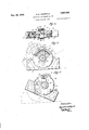
- Figure 1 is a cross section of the device with the bearings in position and Fig. 2, a partial cross section with disengaged shaft.
- Fig. 3 illustrates the clamping device for the shaft.
- Fig. 4 shows the instrument in top plan view.
- Fig. 5 is a front elevation of the instrument.
- Fig. 6 is a rear elevation showing the instrument adjusted at an inclination.
- the casing may be a drum for attachment to another instrument or it may be firmly connected with a channeled base I having a threaded bore for attachment to a tripod.
- the front wall 2 can be removed and has an inspection hole 3, an inspectionhole 4 being provided also in the upper portion of the drum casing 5.
- the rear wall 8 carries on the boss I4 an oscillatory arm I5 with the index I5 and the level I7 for adjusting a definite inclination.
- a pair of scissors On the inner side of the front wall of the casing a pair of scissors is arranged, having lower 20 arms I 8d and upper arms
- An eccentric I9 on the inner end of a turnable knob engages between the lower arms I 8a of the scissors and spreads these arms asunder if it is turned by means of the knob so that its large portion is in 25 horizontal position.
- the upper arms I 8d are then pressed against the shaft 9 and brake the same.
- the eccentric I9 has to be turned into the inoperative position releasing the lower arms I8a which are then pulled together by 30 the action of a spring so that the upper arms I8b open and move away from the shaft 9.
- a bush 25 with the screwed in nipple 26 is screwed carrying the second point bearing 21.
- 28 is a check nut for the nipple 26.
- the bush 25 carries the finger 3S.
- are provided and 32 are the center heads.
- the device is operated as follows:
- the bearing 21 is adjusted by means of the nipple 26 while the check nut 28 is released 50 which is then tightened again.
- the screwing of bush 25 results va the nipple 26 in pressing off and tensioning of the spring 2i! and the carrier 24.
- the carriers 24, 23 are free within their path 3
- the center points are now in position 55 and the spring 20 exerts a slight pressure.
- the spring 24 follows and by engaging the right-hand head 32 draws the shaft 9 along and thus draws the left-hand center 32 from the bearing 2
- the spring 24 hugs the wall 2 and finally the bearing 2'! is drawn off from the right- ⁇ hand center.
- the shaft 8 now rests only on the carriers 23, 24 which lock it against longitudinal displacement while the friction between the carriers and heads 32 brakes it against rotation.
- the path of rotation of the bush 25 is dimensioned so that the path of the finger 30 between the stops 29 will be sucient for it.
- the hollow screw 25 For disengaging the shaft 9 and its dead centre 32 the hollow screw 25 has to be unscrewed.
- the carrier 24 which normally bears resiliently against the inner end of the hollow screw 25 moves during the unwinding of this screw towards the inner surface of wall 2 of the casing until it bears against the collar of the right dead centre 32 and shifts the shaft to the right until the base face of the left dead centre bears against the carrier 23.
- the shaft 9 is thus completely disengaged from the bearings 21 and 2
- a shaft having bearing portions centrally of the ends thereof, bearings for said shaft mounted in said device for adjustment axially of the shaft to engage or disengage the bearing portions thereof, and aumliary bearing members one of which is a spring member, mounted in said device in position to carry said shaft when disengaged from said rst mentioned bearings and s aid shaft and auxiliary bearings having cooperating means to protect the shaft against excessive axial displacement, a drum-like casing accommodating the device and having a front and rear wall, a boss attached to the rear wall of said casing, an arm adapted to oscillate on said boss, and an index and level connected with said arm to adjust a certain inclination.
- a shaft having bearing portions centrally of the ends thereof, bearings for said shaft mounted in said device for adjustment axially of the shaft to engage or disengage the bearing portions thereof, and auxiliary 10 bearing members one of which is a spring member, mounted in said device in position to carry said shaft when disengaged from said first mentioned bearings and said shaft and auxiliary bearings having cooperating means to protect the shaft against excessive axial displacement.
- a drumlike casing a removable front wall in the said casing, there being an inspection hole in the said front wall, a scale firmly secured to the said front wall and extending halfway into the said inspection hole, a rear wall in the said casing, there being an inspection hole in the upper part of the drum-like casing, a scale fixed to the said rear wall and extending halfway into the said inspection hole in the said drum-like casing, a freely oscillating alidade scale on the shaft extending into the remaining halves of the said inspection holes, and a weight attached to the said alidade scale.
- auxiliary bearings consist of a leaf spring and a rigid carrier
- said device including a cas-v ing, a removable front wall for the casing, said shaft having a neck adjacent each end thereof, said spring member and said carrier each having means to engage one of said necks and thereby being adapted to hold said shaft when same is in disengaged position, the said spring elastically pressing outwardly toward one of said bearing portions, and adapted to engage said front wall, when holding the shaft, said bearings serving as a carrier for said shaft and insuring it against excessive axial displacement.
Description
Nov. 26, 1935. A, 5., AEGERTER 2,022,452
DIRECTION MEASURING DEVICE Filed June 19, 1931 2 Sheets-Sheet 1 v. vnul/11111110110 I {gd- Nov. 26, 1935. A. s. AEGERTER DIRECTION MEASURING DEVICE 2 Sheets-Sheet 2 Filed June 19, 1931 Patented Nov. 26, 1935 UNITED STATES @ATENT OFFICE Application June 19, 1931, seria1N0.545,524 In France July 2l, 1930 4 Claims. (Cl. 33-215.1)
The present invention relates to a direction measuring device for determining inclinations relative to a vertical and horizontal plane.
Instruments of this class, in which a pointer oscillating about an axis and adjustable by gravity is provided which moves over a scale projecting inwardly within a circularmount have been proposed already, but they suffer from the drawback that the scale can be read only from the side. In practical work as, for instance, in building operations, it often happens, however, that the instrument must be used on the ground or even under water, and in such cases it has been found quite inconvenient to determine the angle of inclination, while, according to the invention, an inclination can be determined not only from the side but from the top also. Another defect of all existing types of measuring instrumentsA of this class is that the centers of the shaft gradually, owing to the shaking during transportation, work out their bearings to such an extent that the precision character of the instrument is affected. Bearing nipples for scales, Compasses, magnetic instruments and the like, which can be unscrewed during transportation, are known already, but this arrangement provides merely for removing the shaft from its bearings. 'Ihe novel feature of the present invention, on the other hand, resides in the fact that the shaft, while the bearings are withdrawn, is held by two special spring bearings which carry the shaft and at the same time secure it against lateral displacement.
By way of example, one embodiment of the invention is illustrated in the accompanying drawings, in which Figure 1 is a cross section of the device with the bearings in position and Fig. 2, a partial cross section with disengaged shaft.
Fig. 3 illustrates the clamping device for the shaft.
Fig. 4 shows the instrument in top plan view.
Fig. 5 is a front elevation of the instrument.
Fig. 6 is a rear elevation showing the instrument adjusted at an inclination.
The casing may be a drum for attachment to another instrument or it may be firmly connected with a channeled base I having a threaded bore for attachment to a tripod. The front wall 2 can be removed and has an inspection hole 3, an inspectionhole 4 being provided also in the upper portion of the drum casing 5. A scale 6,
. one half of which extends into the hole 3, is firmly secured to the front wall 2, and a rigid scale 1, one half of which extends into the hole 4, is 'attached to the rear wall 8, alidade scale I Il, which fills up the remaining halves of the holes 3 and 4 and is provided at its lowest point with the weight I I, is firmly secured to the shaft 9 whose bearings will be described below. For accurate reading, an arm I2 with two reading 5 magniers I3 disposed above the scales vis provided.
The rear wall 8 carries on the boss I4 an oscillatory arm I5 with the index I5 and the level I7 for adjusting a definite inclination.
For example if a certain inclination or gradient has been set by means of the scales 6 and I@ or 'I and I9 and this inclination is repeatedly required, the level I'I is brought into such a position that it operates in this particular inclination. Thus further inclinations of the same steepness can be set by means ofthis level I1 without its being necessary to read the scales.
On the inner side of the front wall of the casing a pair of scissors is arranged, having lower 20 arms I 8d and upper arms |82). An eccentric I9 on the inner end of a turnable knob engages between the lower arms I 8a of the scissors and spreads these arms asunder if it is turned by means of the knob so that its large portion is in 25 horizontal position. The upper arms I 8d are then pressed against the shaft 9 and brake the same. To liberate the shaft 9 the eccentric I9 has to be turned into the inoperative position releasing the lower arms I8a which are then pulled together by 30 the action of a spring so that the upper arms I8b open and move away from the shaft 9.
Now the arrangement of the shaft 9 with its disengaging device will be described. To the rear wall 8 a laminated spring 26 with the point 35 bearing 2| is secured. In front of the upper end of the spring a small set screw 22 is disposed and on the inside of the wall 8 a rigid carrier 23 is positioned while a second resilient carrier 24 is found inside the casing. 40
Into the front wall 2 a bush 25 with the screwed in nipple 26 is screwed carrying the second point bearing 21. 28 is a check nut for the nipple 26. In the wall 2 two stops 29 are provided and the bush 25 carries the finger 3S. In the shaft 9 45 two journals 3| are provided and 32 are the center heads.
The device is operated as follows:
First the bearing 21 is adjusted by means of the nipple 26 while the check nut 28 is released 50 which is then tightened again. The screwing of bush 25 results va the nipple 26 in pressing off and tensioning of the spring 2i! and the carrier 24. The carriers 24, 23 are free within their path 3|. The center points are now in position 55 and the spring 20 exerts a slight pressure. When the bush 25 is turned back the spring 20 follows until it rests against the screw 22 and is thus rendere-d inoperative. This movement of the spring is determined by adjusting the screw 22. Then the spring 24 follows and by engaging the right-hand head 32 draws the shaft 9 along and thus draws the left-hand center 32 from the bearing 2| while the head 32 moves towards the carrier 23. The spring 24 hugs the wall 2 and finally the bearing 2'! is drawn off from the right-` hand center. The shaft 8 now rests only on the carriers 23, 24 which lock it against longitudinal displacement while the friction between the carriers and heads 32 brakes it against rotation.
The path of rotation of the bush 25 is dimensioned so that the path of the finger 30 between the stops 29 will be sucient for it.
For disengaging the shaft 9 and its dead centre 32 the hollow screw 25 has to be unscrewed. The carrier 24 which normally bears resiliently against the inner end of the hollow screw 25 moves during the unwinding of this screw towards the inner surface of wall 2 of the casing until it bears against the collar of the right dead centre 32 and shifts the shaft to the right until the base face of the left dead centre bears against the carrier 23. The shaft 9 is thus completely disengaged from the bearings 21 and 2| and held by the carriers cr relief bearings 23 and 24.
I claim:-
l. In a direction measuring device for determining angles of inclination, a shaft having bearing portions centrally of the ends thereof, bearings for said shaft mounted in said device for adjustment axially of the shaft to engage or disengage the bearing portions thereof, and aumliary bearing members one of which is a spring member, mounted in said device in position to carry said shaft when disengaged from said rst mentioned bearings and s aid shaft and auxiliary bearings having cooperating means to protect the shaft against excessive axial displacement, a drum-like casing accommodating the device and having a front and rear wall, a boss attached to the rear wall of said casing, an arm adapted to oscillate on said boss, and an index and level connected with said arm to adjust a certain inclination.
2. In a direction measuring device for determining angles of inclination, a shaft having bearing portions centrally of the ends thereof, bearings for said shaft mounted in said device for adjustment axially of the shaft to engage or disengage the bearing portions thereof, and auxiliary 10 bearing members one of which is a spring member, mounted in said device in position to carry said shaft when disengaged from said first mentioned bearings and said shaft and auxiliary bearings having cooperating means to protect the shaft against excessive axial displacement.
3. In a device according to claim 2 a drumlike casing, a removable front wall in the said casing, there being an inspection hole in the said front wall, a scale firmly secured to the said front wall and extending halfway into the said inspection hole, a rear wall in the said casing, there being an inspection hole in the upper part of the drum-like casing, a scale fixed to the said rear wall and extending halfway into the said inspection hole in the said drum-like casing, a freely oscillating alidade scale on the shaft extending into the remaining halves of the said inspection holes, and a weight attached to the said alidade scale.
4. In a device according to claim 2, in which the auxiliary bearings consist of a leaf spring and a rigid carrier, said device including a cas-v ing, a removable front wall for the casing, said shaft having a neck adjacent each end thereof, said spring member and said carrier each having means to engage one of said necks and thereby being adapted to hold said shaft when same is in disengaged position, the said spring elastically pressing outwardly toward one of said bearing portions, and adapted to engage said front wall, when holding the shaft, said bearings serving as a carrier for said shaft and insuring it against excessive axial displacement.
AUGUST SAMUEL AEGER'I'ER. 5
Applications Claiming Priority (1)
| Application Number | Priority Date | Filing Date | Title |
|---|---|---|---|
| FR2022452X | 1930-07-21 |
Publications (1)
| Publication Number | Publication Date |
|---|---|
| US2022452A true US2022452A (en) | 1935-11-26 |
Family
ID=9683093
Family Applications (1)
| Application Number | Title | Priority Date | Filing Date |
|---|---|---|---|
| US545524A Expired - Lifetime US2022452A (en) | 1930-07-21 | 1931-06-19 | Direction measuring device |
Country Status (1)
| Country | Link |
|---|---|
| US (1) | US2022452A (en) |
Cited By (9)
| Publication number | Priority date | Publication date | Assignee | Title |
|---|---|---|---|---|
| US2498083A (en) * | 1948-07-10 | 1950-02-21 | Rollis A Kennedy | Pocket clinometer |
| US2505884A (en) * | 1945-11-06 | 1950-05-02 | Ronald L R Cockerell | Pendulum inclinometer |
| US2565381A (en) * | 1949-08-15 | 1951-08-21 | Jack R Leighton | Device for measuring angular body movements |
| US2581630A (en) * | 1945-09-10 | 1952-01-08 | Fmc Corp | Wheel gauging apparatus |
| US2632958A (en) * | 1950-12-08 | 1953-03-31 | Masters William S De | Device for determining grade slopes |
| US2654158A (en) * | 1950-05-02 | 1953-10-06 | Carrle Gros Lutz | Steel square calculator |
| US3047961A (en) * | 1956-10-09 | 1962-08-07 | Technincal Oil Tool Corp Ltd | High angle inclination instrument |
| US4394799A (en) * | 1981-08-31 | 1983-07-26 | Moree Elwood D | Conduit bending plane indicator |
| WO1988007174A1 (en) * | 1987-03-09 | 1988-09-22 | Kurt Fischer | Protractor with a circular and shaped bubble level |
-
1931
- 1931-06-19 US US545524A patent/US2022452A/en not_active Expired - Lifetime
Cited By (9)
| Publication number | Priority date | Publication date | Assignee | Title |
|---|---|---|---|---|
| US2581630A (en) * | 1945-09-10 | 1952-01-08 | Fmc Corp | Wheel gauging apparatus |
| US2505884A (en) * | 1945-11-06 | 1950-05-02 | Ronald L R Cockerell | Pendulum inclinometer |
| US2498083A (en) * | 1948-07-10 | 1950-02-21 | Rollis A Kennedy | Pocket clinometer |
| US2565381A (en) * | 1949-08-15 | 1951-08-21 | Jack R Leighton | Device for measuring angular body movements |
| US2654158A (en) * | 1950-05-02 | 1953-10-06 | Carrle Gros Lutz | Steel square calculator |
| US2632958A (en) * | 1950-12-08 | 1953-03-31 | Masters William S De | Device for determining grade slopes |
| US3047961A (en) * | 1956-10-09 | 1962-08-07 | Technincal Oil Tool Corp Ltd | High angle inclination instrument |
| US4394799A (en) * | 1981-08-31 | 1983-07-26 | Moree Elwood D | Conduit bending plane indicator |
| WO1988007174A1 (en) * | 1987-03-09 | 1988-09-22 | Kurt Fischer | Protractor with a circular and shaped bubble level |
Similar Documents
| Publication | Publication Date | Title |
|---|---|---|
| US2022452A (en) | Direction measuring device | |
| US3009250A (en) | Spirit level and grade indicator | |
| US2581630A (en) | Wheel gauging apparatus | |
| US2425453A (en) | Grinding wheel dressing tool | |
| US2111829A (en) | Orientation compass | |
| US1887437A (en) | Micrometer | |
| US2387440A (en) | Coordinate measuring stage | |
| US2614329A (en) | Protractor | |
| US2645860A (en) | Wheel testing device | |
| US2914361A (en) | Balances | |
| US1657546A (en) | Adjustable level and plumb device | |
| US2194995A (en) | Device for determining the inclination of an axle to two different planes | |
| US3026625A (en) | Surveying instrument | |
| US1826219A (en) | Grinding wheel trimming fixture | |
| US1540319A (en) | eisele | |
| US2190866A (en) | Indicating instrument | |
| US2614552A (en) | Grinding wheel dresser | |
| US1339384A (en) | Gage | |
| US610952A (en) | Level | |
| US1539543A (en) | Protractor level | |
| US3161966A (en) | Gravity level | |
| US2660796A (en) | Disk measuring device | |
| US370013A (en) | Oscae b | |
| US1309486A (en) | Solar transit | |
| US1419306A (en) | Indicating surface gauge |