US20220184882A1 - System for additively manufacturing composite structure - Google Patents
System for additively manufacturing composite structure Download PDFInfo
- Publication number
- US20220184882A1 US20220184882A1 US17/654,033 US202217654033A US2022184882A1 US 20220184882 A1 US20220184882 A1 US 20220184882A1 US 202217654033 A US202217654033 A US 202217654033A US 2022184882 A1 US2022184882 A1 US 2022184882A1
- Authority
- US
- United States
- Prior art keywords
- energy
- exposing
- cure enhancer
- cure
- compactor
- Prior art date
- Legal status (The legal status is an assumption and is not a legal conclusion. Google has not performed a legal analysis and makes no representation as to the accuracy of the status listed.)
- Granted
Links
Images


Classifications
-
- B—PERFORMING OPERATIONS; TRANSPORTING
- B29—WORKING OF PLASTICS; WORKING OF SUBSTANCES IN A PLASTIC STATE IN GENERAL
- B29C—SHAPING OR JOINING OF PLASTICS; SHAPING OF MATERIAL IN A PLASTIC STATE, NOT OTHERWISE PROVIDED FOR; AFTER-TREATMENT OF THE SHAPED PRODUCTS, e.g. REPAIRING
- B29C64/00—Additive manufacturing, i.e. manufacturing of three-dimensional [3D] objects by additive deposition, additive agglomeration or additive layering, e.g. by 3D printing, stereolithography or selective laser sintering
- B29C64/10—Processes of additive manufacturing
- B29C64/106—Processes of additive manufacturing using only liquids or viscous materials, e.g. depositing a continuous bead of viscous material
- B29C64/118—Processes of additive manufacturing using only liquids or viscous materials, e.g. depositing a continuous bead of viscous material using filamentary material being melted, e.g. fused deposition modelling [FDM]
-
- B—PERFORMING OPERATIONS; TRANSPORTING
- B29—WORKING OF PLASTICS; WORKING OF SUBSTANCES IN A PLASTIC STATE IN GENERAL
- B29C—SHAPING OR JOINING OF PLASTICS; SHAPING OF MATERIAL IN A PLASTIC STATE, NOT OTHERWISE PROVIDED FOR; AFTER-TREATMENT OF THE SHAPED PRODUCTS, e.g. REPAIRING
- B29C64/00—Additive manufacturing, i.e. manufacturing of three-dimensional [3D] objects by additive deposition, additive agglomeration or additive layering, e.g. by 3D printing, stereolithography or selective laser sintering
- B29C64/10—Processes of additive manufacturing
- B29C64/106—Processes of additive manufacturing using only liquids or viscous materials, e.g. depositing a continuous bead of viscous material
-
- B—PERFORMING OPERATIONS; TRANSPORTING
- B29—WORKING OF PLASTICS; WORKING OF SUBSTANCES IN A PLASTIC STATE IN GENERAL
- B29C—SHAPING OR JOINING OF PLASTICS; SHAPING OF MATERIAL IN A PLASTIC STATE, NOT OTHERWISE PROVIDED FOR; AFTER-TREATMENT OF THE SHAPED PRODUCTS, e.g. REPAIRING
- B29C64/00—Additive manufacturing, i.e. manufacturing of three-dimensional [3D] objects by additive deposition, additive agglomeration or additive layering, e.g. by 3D printing, stereolithography or selective laser sintering
- B29C64/10—Processes of additive manufacturing
- B29C64/165—Processes of additive manufacturing using a combination of solid and fluid materials, e.g. a powder selectively bound by a liquid binder, catalyst, inhibitor or energy absorber
-
- B—PERFORMING OPERATIONS; TRANSPORTING
- B29—WORKING OF PLASTICS; WORKING OF SUBSTANCES IN A PLASTIC STATE IN GENERAL
- B29C—SHAPING OR JOINING OF PLASTICS; SHAPING OF MATERIAL IN A PLASTIC STATE, NOT OTHERWISE PROVIDED FOR; AFTER-TREATMENT OF THE SHAPED PRODUCTS, e.g. REPAIRING
- B29C64/00—Additive manufacturing, i.e. manufacturing of three-dimensional [3D] objects by additive deposition, additive agglomeration or additive layering, e.g. by 3D printing, stereolithography or selective laser sintering
- B29C64/10—Processes of additive manufacturing
- B29C64/188—Processes of additive manufacturing involving additional operations performed on the added layers, e.g. smoothing, grinding or thickness control
-
- B—PERFORMING OPERATIONS; TRANSPORTING
- B29—WORKING OF PLASTICS; WORKING OF SUBSTANCES IN A PLASTIC STATE IN GENERAL
- B29C—SHAPING OR JOINING OF PLASTICS; SHAPING OF MATERIAL IN A PLASTIC STATE, NOT OTHERWISE PROVIDED FOR; AFTER-TREATMENT OF THE SHAPED PRODUCTS, e.g. REPAIRING
- B29C64/00—Additive manufacturing, i.e. manufacturing of three-dimensional [3D] objects by additive deposition, additive agglomeration or additive layering, e.g. by 3D printing, stereolithography or selective laser sintering
- B29C64/20—Apparatus for additive manufacturing; Details thereof or accessories therefor
- B29C64/205—Means for applying layers
- B29C64/209—Heads; Nozzles
-
- B—PERFORMING OPERATIONS; TRANSPORTING
- B29—WORKING OF PLASTICS; WORKING OF SUBSTANCES IN A PLASTIC STATE IN GENERAL
- B29C—SHAPING OR JOINING OF PLASTICS; SHAPING OF MATERIAL IN A PLASTIC STATE, NOT OTHERWISE PROVIDED FOR; AFTER-TREATMENT OF THE SHAPED PRODUCTS, e.g. REPAIRING
- B29C64/00—Additive manufacturing, i.e. manufacturing of three-dimensional [3D] objects by additive deposition, additive agglomeration or additive layering, e.g. by 3D printing, stereolithography or selective laser sintering
- B29C64/20—Apparatus for additive manufacturing; Details thereof or accessories therefor
- B29C64/205—Means for applying layers
- B29C64/218—Rollers
-
- B—PERFORMING OPERATIONS; TRANSPORTING
- B29—WORKING OF PLASTICS; WORKING OF SUBSTANCES IN A PLASTIC STATE IN GENERAL
- B29C—SHAPING OR JOINING OF PLASTICS; SHAPING OF MATERIAL IN A PLASTIC STATE, NOT OTHERWISE PROVIDED FOR; AFTER-TREATMENT OF THE SHAPED PRODUCTS, e.g. REPAIRING
- B29C64/00—Additive manufacturing, i.e. manufacturing of three-dimensional [3D] objects by additive deposition, additive agglomeration or additive layering, e.g. by 3D printing, stereolithography or selective laser sintering
- B29C64/20—Apparatus for additive manufacturing; Details thereof or accessories therefor
- B29C64/227—Driving means
- B29C64/232—Driving means for motion along the axis orthogonal to the plane of a layer
-
- B—PERFORMING OPERATIONS; TRANSPORTING
- B29—WORKING OF PLASTICS; WORKING OF SUBSTANCES IN A PLASTIC STATE IN GENERAL
- B29C—SHAPING OR JOINING OF PLASTICS; SHAPING OF MATERIAL IN A PLASTIC STATE, NOT OTHERWISE PROVIDED FOR; AFTER-TREATMENT OF THE SHAPED PRODUCTS, e.g. REPAIRING
- B29C64/00—Additive manufacturing, i.e. manufacturing of three-dimensional [3D] objects by additive deposition, additive agglomeration or additive layering, e.g. by 3D printing, stereolithography or selective laser sintering
- B29C64/20—Apparatus for additive manufacturing; Details thereof or accessories therefor
- B29C64/227—Driving means
- B29C64/241—Driving means for rotary motion
-
- B—PERFORMING OPERATIONS; TRANSPORTING
- B29—WORKING OF PLASTICS; WORKING OF SUBSTANCES IN A PLASTIC STATE IN GENERAL
- B29C—SHAPING OR JOINING OF PLASTICS; SHAPING OF MATERIAL IN A PLASTIC STATE, NOT OTHERWISE PROVIDED FOR; AFTER-TREATMENT OF THE SHAPED PRODUCTS, e.g. REPAIRING
- B29C64/00—Additive manufacturing, i.e. manufacturing of three-dimensional [3D] objects by additive deposition, additive agglomeration or additive layering, e.g. by 3D printing, stereolithography or selective laser sintering
- B29C64/20—Apparatus for additive manufacturing; Details thereof or accessories therefor
- B29C64/245—Platforms or substrates
-
- B—PERFORMING OPERATIONS; TRANSPORTING
- B29—WORKING OF PLASTICS; WORKING OF SUBSTANCES IN A PLASTIC STATE IN GENERAL
- B29C—SHAPING OR JOINING OF PLASTICS; SHAPING OF MATERIAL IN A PLASTIC STATE, NOT OTHERWISE PROVIDED FOR; AFTER-TREATMENT OF THE SHAPED PRODUCTS, e.g. REPAIRING
- B29C64/00—Additive manufacturing, i.e. manufacturing of three-dimensional [3D] objects by additive deposition, additive agglomeration or additive layering, e.g. by 3D printing, stereolithography or selective laser sintering
- B29C64/20—Apparatus for additive manufacturing; Details thereof or accessories therefor
- B29C64/264—Arrangements for irradiation
-
- B—PERFORMING OPERATIONS; TRANSPORTING
- B29—WORKING OF PLASTICS; WORKING OF SUBSTANCES IN A PLASTIC STATE IN GENERAL
- B29C—SHAPING OR JOINING OF PLASTICS; SHAPING OF MATERIAL IN A PLASTIC STATE, NOT OTHERWISE PROVIDED FOR; AFTER-TREATMENT OF THE SHAPED PRODUCTS, e.g. REPAIRING
- B29C64/00—Additive manufacturing, i.e. manufacturing of three-dimensional [3D] objects by additive deposition, additive agglomeration or additive layering, e.g. by 3D printing, stereolithography or selective laser sintering
- B29C64/20—Apparatus for additive manufacturing; Details thereof or accessories therefor
- B29C64/295—Heating elements
-
- B—PERFORMING OPERATIONS; TRANSPORTING
- B29—WORKING OF PLASTICS; WORKING OF SUBSTANCES IN A PLASTIC STATE IN GENERAL
- B29C—SHAPING OR JOINING OF PLASTICS; SHAPING OF MATERIAL IN A PLASTIC STATE, NOT OTHERWISE PROVIDED FOR; AFTER-TREATMENT OF THE SHAPED PRODUCTS, e.g. REPAIRING
- B29C64/00—Additive manufacturing, i.e. manufacturing of three-dimensional [3D] objects by additive deposition, additive agglomeration or additive layering, e.g. by 3D printing, stereolithography or selective laser sintering
- B29C64/30—Auxiliary operations or equipment
- B29C64/307—Handling of material to be used in additive manufacturing
- B29C64/314—Preparation
-
- B—PERFORMING OPERATIONS; TRANSPORTING
- B29—WORKING OF PLASTICS; WORKING OF SUBSTANCES IN A PLASTIC STATE IN GENERAL
- B29C—SHAPING OR JOINING OF PLASTICS; SHAPING OF MATERIAL IN A PLASTIC STATE, NOT OTHERWISE PROVIDED FOR; AFTER-TREATMENT OF THE SHAPED PRODUCTS, e.g. REPAIRING
- B29C64/00—Additive manufacturing, i.e. manufacturing of three-dimensional [3D] objects by additive deposition, additive agglomeration or additive layering, e.g. by 3D printing, stereolithography or selective laser sintering
- B29C64/30—Auxiliary operations or equipment
- B29C64/307—Handling of material to be used in additive manufacturing
- B29C64/321—Feeding
- B29C64/336—Feeding of two or more materials
-
- B—PERFORMING OPERATIONS; TRANSPORTING
- B29—WORKING OF PLASTICS; WORKING OF SUBSTANCES IN A PLASTIC STATE IN GENERAL
- B29C—SHAPING OR JOINING OF PLASTICS; SHAPING OF MATERIAL IN A PLASTIC STATE, NOT OTHERWISE PROVIDED FOR; AFTER-TREATMENT OF THE SHAPED PRODUCTS, e.g. REPAIRING
- B29C64/00—Additive manufacturing, i.e. manufacturing of three-dimensional [3D] objects by additive deposition, additive agglomeration or additive layering, e.g. by 3D printing, stereolithography or selective laser sintering
- B29C64/30—Auxiliary operations or equipment
- B29C64/386—Data acquisition or data processing for additive manufacturing
- B29C64/393—Data acquisition or data processing for additive manufacturing for controlling or regulating additive manufacturing processes
-
- B—PERFORMING OPERATIONS; TRANSPORTING
- B29—WORKING OF PLASTICS; WORKING OF SUBSTANCES IN A PLASTIC STATE IN GENERAL
- B29C—SHAPING OR JOINING OF PLASTICS; SHAPING OF MATERIAL IN A PLASTIC STATE, NOT OTHERWISE PROVIDED FOR; AFTER-TREATMENT OF THE SHAPED PRODUCTS, e.g. REPAIRING
- B29C70/00—Shaping composites, i.e. plastics material comprising reinforcements, fillers or preformed parts, e.g. inserts
- B29C70/04—Shaping composites, i.e. plastics material comprising reinforcements, fillers or preformed parts, e.g. inserts comprising reinforcements only, e.g. self-reinforcing plastics
- B29C70/06—Fibrous reinforcements only
- B29C70/10—Fibrous reinforcements only characterised by the structure of fibrous reinforcements, e.g. hollow fibres
- B29C70/16—Fibrous reinforcements only characterised by the structure of fibrous reinforcements, e.g. hollow fibres using fibres of substantial or continuous length
-
- B—PERFORMING OPERATIONS; TRANSPORTING
- B29—WORKING OF PLASTICS; WORKING OF SUBSTANCES IN A PLASTIC STATE IN GENERAL
- B29C—SHAPING OR JOINING OF PLASTICS; SHAPING OF MATERIAL IN A PLASTIC STATE, NOT OTHERWISE PROVIDED FOR; AFTER-TREATMENT OF THE SHAPED PRODUCTS, e.g. REPAIRING
- B29C70/00—Shaping composites, i.e. plastics material comprising reinforcements, fillers or preformed parts, e.g. inserts
- B29C70/04—Shaping composites, i.e. plastics material comprising reinforcements, fillers or preformed parts, e.g. inserts comprising reinforcements only, e.g. self-reinforcing plastics
- B29C70/28—Shaping operations therefor
- B29C70/30—Shaping by lay-up, i.e. applying fibres, tape or broadsheet on a mould, former or core; Shaping by spray-up, i.e. spraying of fibres on a mould, former or core
- B29C70/38—Automated lay-up, e.g. using robots, laying filaments according to predetermined patterns
-
- B—PERFORMING OPERATIONS; TRANSPORTING
- B33—ADDITIVE MANUFACTURING TECHNOLOGY
- B33Y—ADDITIVE MANUFACTURING, i.e. MANUFACTURING OF THREE-DIMENSIONAL [3D] OBJECTS BY ADDITIVE DEPOSITION, ADDITIVE AGGLOMERATION OR ADDITIVE LAYERING, e.g. BY 3D PRINTING, STEREOLITHOGRAPHY OR SELECTIVE LASER SINTERING
- B33Y10/00—Processes of additive manufacturing
-
- B—PERFORMING OPERATIONS; TRANSPORTING
- B33—ADDITIVE MANUFACTURING TECHNOLOGY
- B33Y—ADDITIVE MANUFACTURING, i.e. MANUFACTURING OF THREE-DIMENSIONAL [3D] OBJECTS BY ADDITIVE DEPOSITION, ADDITIVE AGGLOMERATION OR ADDITIVE LAYERING, e.g. BY 3D PRINTING, STEREOLITHOGRAPHY OR SELECTIVE LASER SINTERING
- B33Y30/00—Apparatus for additive manufacturing; Details thereof or accessories therefor
-
- B—PERFORMING OPERATIONS; TRANSPORTING
- B33—ADDITIVE MANUFACTURING TECHNOLOGY
- B33Y—ADDITIVE MANUFACTURING, i.e. MANUFACTURING OF THREE-DIMENSIONAL [3D] OBJECTS BY ADDITIVE DEPOSITION, ADDITIVE AGGLOMERATION OR ADDITIVE LAYERING, e.g. BY 3D PRINTING, STEREOLITHOGRAPHY OR SELECTIVE LASER SINTERING
- B33Y40/00—Auxiliary operations or equipment, e.g. for material handling
-
- B—PERFORMING OPERATIONS; TRANSPORTING
- B33—ADDITIVE MANUFACTURING TECHNOLOGY
- B33Y—ADDITIVE MANUFACTURING, i.e. MANUFACTURING OF THREE-DIMENSIONAL [3D] OBJECTS BY ADDITIVE DEPOSITION, ADDITIVE AGGLOMERATION OR ADDITIVE LAYERING, e.g. BY 3D PRINTING, STEREOLITHOGRAPHY OR SELECTIVE LASER SINTERING
- B33Y50/00—Data acquisition or data processing for additive manufacturing
- B33Y50/02—Data acquisition or data processing for additive manufacturing for controlling or regulating additive manufacturing processes
-
- G—PHYSICS
- G06—COMPUTING OR CALCULATING; COUNTING
- G06F—ELECTRIC DIGITAL DATA PROCESSING
- G06F30/00—Computer-aided design [CAD]
- G06F30/20—Design optimisation, verification or simulation
- G06F30/23—Design optimisation, verification or simulation using finite element methods [FEM] or finite difference methods [FDM]
-
- B—PERFORMING OPERATIONS; TRANSPORTING
- B29—WORKING OF PLASTICS; WORKING OF SUBSTANCES IN A PLASTIC STATE IN GENERAL
- B29K—INDEXING SCHEME ASSOCIATED WITH SUBCLASSES B29B, B29C OR B29D, RELATING TO MOULDING MATERIALS OR TO MATERIALS FOR MOULDS, REINFORCEMENTS, FILLERS OR PREFORMED PARTS, e.g. INSERTS
- B29K2105/00—Condition, form or state of moulded material or of the material to be shaped
- B29K2105/06—Condition, form or state of moulded material or of the material to be shaped containing reinforcements, fillers or inserts
- B29K2105/08—Condition, form or state of moulded material or of the material to be shaped containing reinforcements, fillers or inserts of continuous length, e.g. cords, rovings, mats, fabrics, strands or yarns
-
- B—PERFORMING OPERATIONS; TRANSPORTING
- B33—ADDITIVE MANUFACTURING TECHNOLOGY
- B33Y—ADDITIVE MANUFACTURING, i.e. MANUFACTURING OF THREE-DIMENSIONAL [3D] OBJECTS BY ADDITIVE DEPOSITION, ADDITIVE AGGLOMERATION OR ADDITIVE LAYERING, e.g. BY 3D PRINTING, STEREOLITHOGRAPHY OR SELECTIVE LASER SINTERING
- B33Y70/00—Materials specially adapted for additive manufacturing
- B33Y70/10—Composites of different types of material, e.g. mixtures of ceramics and polymers or mixtures of metals and biomaterials
Definitions
- the present disclosure relates generally to a manufacturing system and, more particularly, to a system for additively manufacturing composite structures.
- Continuous fiber 3D printing involves the use of continuous fibers embedded within a matrix discharging from a moveable print head.
- the matrix can be a traditional thermoplastic, a powdered metal, a liquid resin (e.g., a UV curable and/or two-part resin), or a combination of any of these and other known matrixes.
- a head-mounted cure enhancer e.g., a UV light, an ultrasonic emitter, a heat source, a catalyst supply, etc.
- a cure enhancer e.g., a UV light, an ultrasonic emitter, a heat source, a catalyst supply, etc.
- CF3D® provides for increased strength, compared to manufacturing processes that do not utilize continuous fiber reinforcement, improvements can be made to the structure and/or operation of existing systems. For example, Applicant has found that greater control over compacting and curing of the reinforcement can improve reinforcement placement, strength, and accuracy.
- the disclosed additive manufacturing system is uniquely configured to provide these improvements and/or to address other issues of the prior art.
- the present disclosure is directed to an additive manufacturing system.
- the additive manufacturing system may include a support, and an outlet configured to discharge a material.
- the outlet may be operatively connected to and moveable by the support in a normal travel direction during material discharge.
- the outlet may include a guide, and a compactor operatively connected to the guide at a trailing location relative to the normal travel direction.
- the compactor may be moveable in an axial direction of the guide.
- the outlet may also include at least one cure enhancer mounted to move with the compactor relative to the guide. The at least one cure enhancer may be configured to expose the material to a cure energy.
- the present disclosure is directed to another additive manufacturing system.
- This additive manufacturing system may include a nozzle configured to discharge continuous reinforcement at least partially wetted with a matrix, at least one cure enhancer configured to expose the matrix to a cure energy after discharge from the nozzle, and a compactor configured to apply a pressure to the matrix-wetted continuous reinforcement after discharge from the nozzle.
- the at least one cure enhancer and the compactor may be mounted to move together relative to the nozzle, in a direction of discharge from the nozzle.
- the present disclosure is directed to a method of additively manufacturing a structure.
- the method may include wetting a continuous reinforcement with a liquid matrix inside of a print head, and discharging the matrix-wetted continuous reinforcement through an outlet of the print head.
- the method may also include pressing a compactor against the matrix-wetted continuous reinforcement after discharging, directing cure energy from at least one cure enhancer toward the matrix-wetted continuous reinforcement after pressing, and moving the at least one cure enhancer with the compactor relative to the outlet in a direction of discharging.
- FIG. 1 is a diagrammatic illustration of an exemplary disclosed additive manufacturing system
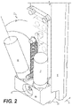
- FIGS. 2 and 3 are diagrammatic illustrations of exemplary disclosed portions of the system of FIG. 1 .
- FIG. 1 illustrates an exemplary system 10 , which may be used to manufacture a composite structure 12 having any desired shape.
- System 10 may include a support 14 and deposition head (“head”) 16 .
- Head 16 may be coupled to and moved by support 14 .
- support 14 is a robotic arm capable of moving head 16 in multiple directions during fabrication of structure 12 .
- Support 14 may alternatively embody a gantry (e.g., an overhead-bridge or single-post gantry) or a hybrid gantry/arm also capable of moving head 16 in multiple directions during fabrication of structure 12 .
- gantry e.g., an overhead-bridge or single-post gantry
- hybrid gantry/arm also capable of moving head 16 in multiple directions during fabrication of structure 12 .
- support 14 is shown as being capable of 6-axis movements, it is contemplated that support 14 may be capable of moving head 16 in a different manner (e.g., along or around a greater or lesser number of axes).
- a drive may mechanically couple head 16 to support 14 , and include components that cooperate to move portions of and/or supply power or materials to head 16 .
- Head 16 may be configured to receive or otherwise contain a matrix (shown as M).
- the matrix may include any types or combinations of materials (e.g., a liquid resin, such as a zero-volatile organic compound resin, a powdered metal, etc.) that are curable.
- exemplary resins include thermosets, single- or multi-part epoxy resins, polyester resins, cationic epoxies, acrylated epoxies, urethanes, esters, thermoplastics, photopolymers, polyepoxides, thiols, alkenes, thiol-enes, and more.
- the matrix inside head 16 may be pressurized (e.g., positively and/or negatively), for example by an external device (e.g., by an extruder, a pump, etc.—not shown) that is fluidly connected to head 16 via a corresponding conduit (not shown).
- the pressure may be generated completely inside of head 16 by a similar type of device.
- the matrix may be gravity-fed into and/or through head 16 .
- the matrix may be fed into head 16 , and pushed or pulled out of head 16 along with one or more continuous reinforcements (shown as R).
- the matrix inside head 16 may need to be kept cool and/or dark in order to inhibit premature curing or otherwise obtain a desired rate of curing after discharge. In other instances, the matrix may need to be kept warm and/or illuminated for similar reasons. In either situation, head 16 may be specially configured (e.g., insulated, temperature-controlled, shielded, etc.) to provide for these needs.
- the matrix may be used to at least partially coat any number of continuous reinforcements (e.g., separate fibers, tows, rovings, socks, and/or sheets of continuous material) and, together with the reinforcements, make up a portion (e.g., a wall) of composite structure 12 .
- the reinforcements may be stored within or otherwise passed through head 16 .
- the reinforcements may be of the same material composition and have the same sizing and cross-sectional shape (e.g., circular, square, rectangular, etc.), or a different material composition with different sizing and/or cross-sectional shapes.
- the reinforcements may include, for example, carbon fibers, vegetable fibers, wood fibers, mineral fibers, glass fibers, plastic fibers, metallic fibers, optical fibers (e.g., tubes), etc. It should be noted that the term “reinforcement” is meant to encompass both structural and non-structural (e.g., functional) types of continuous materials that are at least partially encased in the matrix discharging from head 16 .
- the reinforcements may be at least partially coated with the matrix while the reinforcements are inside head 16 , while the reinforcements are being passed to head 16 , and/or while the reinforcements are discharging from head 16 .
- the matrix, dry (e.g., unimpregnated) reinforcements, and/or reinforcements that are already exposed to the matrix (e.g., pre-impregnated reinforcements) may be transported into head 16 in any manner apparent to one skilled in the art.
- a filler material e.g., chopped fibers, nano particles or tubes, etc.
- additives e.g., thermal initiators, UV initiators, etc.
- One or more cure enhancers (e.g., a UV light, an ultrasonic emitter, a laser, a heater, a catalyst dispenser, etc.) 18 may be mounted proximate (e.g., within, on, and/or adjacent) head 16 and configured to enhance a cure rate and/or quality of the matrix as it is discharged from head 16 .
- Cure enhancer 18 may be controlled to selectively expose portions of structure 12 to energy (e.g., UV light, electromagnetic radiation, vibrations, heat, a chemical catalyst, etc.) during material discharge and the formation of structure 12 .
- the energy may trigger a chemical reaction to occur within the matrix, increase a rate of the chemical reaction, sinter the matrix, harden the matrix, solidify the matrix, polymerize the matrix, or otherwise cause the matrix to cure as it discharges from head 16 .
- the amount of energy produced by cure enhancer 18 may be sufficient to cure the matrix before structure 12 axially grows more than a predetermined length away from head 16 .
- structure 12 is at least partially (e.g., completely) cured before the axial growth length becomes equal to an external diameter of the matrix-coated reinforcement.
- the matrix and/or reinforcement may be discharged together from head 16 via any number of different modes of operation.
- the matrix and/or reinforcement are extruded (e.g., pushed under pressure and/or mechanical force) from head 16 as head 16 is moved by support 14 to create features of structure 12 .
- a second example mode of operation at least the reinforcement is pulled from head 16 , such that a tensile stress is created in the reinforcement during discharge.
- the matrix may cling to the reinforcement and thereby also be pulled from head 16 along with the reinforcement, and/or the matrix may be discharged from head 16 under pressure along with the pulled reinforcement.
- the resulting tension in the reinforcement may increase a strength of structure 12 (e.g., by aligning the reinforcements, inhibiting buckling, equally loading the reinforcements, etc.) after curing of the matrix, while also allowing for a greater length of unsupported structure 12 to have a straighter trajectory. That is, the tension in the reinforcement remaining after curing of the matrix may act against the force of gravity (e.g., directly and/or indirectly by creating moments that oppose gravity) to provide support for structure 12 .
- the force of gravity e.g., directly and/or indirectly by creating moments that oppose gravity
- the reinforcement may be pulled from head 16 as a result of head 16 being moved by support 14 away from an anchor point (e.g., a print bed, an existing surface of structure 12 , a fixture, etc.).
- an anchor point e.g., a print bed, an existing surface of structure 12 , a fixture, etc.
- a length of matrix-impregnated reinforcement may be pulled and/or pushed from head 16 , deposited onto the anchor point, and at least partially cured, such that the discharged material adheres (or is otherwise coupled) to the anchor point.
- head 16 may be moved away from the anchor point, and the relative movement may cause the reinforcement to be pulled from head 16 .
- the movement of reinforcement through head 16 may be selectively assisted via one or more internal feed mechanisms, if desired.
- the discharge rate of reinforcement from head 16 may primarily be the result of relative movement between head 16 and the anchor point, such that tension is created within the reinforcement.
- the anchor point could be moved away from head 16 instead of or in addition to head 16 being moved away from the anchor point.
- Head 16 may include, among other things, an outlet 22 and a matrix reservoir 24 located upstream of outlet 22 .
- outlet 22 is a single-channel outlet configured to discharge composite material having a generally circular, tubular, or rectangular cross-section.
- the configuration of head 16 may allow outlet 22 to be swapped out for another outlet that discharges multiple channels of composite material having different shapes (e.g., a flat or sheet-like cross-section, a multi-track cross-section, etc.).
- Fibers, tubes, and/or other reinforcements may pass through matrix reservoir 24 (e.g., through one or more internal wetting mechanisms 26 located inside of reservoir 24 ) and be wetted (e.g., at least partially coated and/or fully saturated) with matrix prior to discharge.
- controller 28 may be provided and communicatively coupled with support 14 and head 16 .
- Each controller 28 may embody a single processor or multiple processors that are programmed and/or otherwise configured to control an operation of system 10 .
- Controller 28 may include one or more general or special purpose processors or microprocessors.
- Controller 28 may further include or be associated with a memory for storing data such as, for example, design limits, performance characteristics, operational instructions, tool paths, and corresponding parameters of each component of system 10 .
- Various other known circuits may be associated with controller 28 , including power supply circuitry, signal-conditioning circuitry, solenoid driver circuitry, communication circuitry, and other appropriate circuitry.
- controller 28 may be capable of communicating with other components of system 10 via wired and/or wireless transmission.
- One or more maps may be stored within the memory of controller 28 and used during fabrication of structure 12 .
- Each of these maps may include a collection of data in the form of lookup tables, graphs, and/or equations.
- the maps may be used by controller 28 to determine movements of head 16 required to produce desired geometry (e.g., size, shape, material composition, performance parameters, and/or contour) of structure 12 , and to regulate operation of cure enhancer(s) 18 and/or other related components in coordination with the movements.
- outlet 22 may be an assembly of components that cooperate to accurately place matrix-wetted reinforcement(s) and thereby form structure 12 (referring to FIG. 1 ).
- These components may include, among other things, a guide or nozzle 30 located downstream of wetting mechanism 26 (referring to FIG. 1 ), and a compactor 32 that trails nozzle 30 (e.g., relative to a normal travel direction of head 16 during material discharge, as represented by an arrow 34 ). It is contemplated that either of nozzle 30 or compactor 32 may function as a tool center point (TCP) of head 16 , to position the matrix-wetted reinforcement(s) prior to curing when exposed to energy by cure enhancer(s) 18 .
- TCP tool center point
- the matrix-wetted reinforcement(s) may pass through one or more features (e.g., channels, grooves, protrusions, etc.) of nozzle 30 that help to maintain desired trajectories (e.g., separation between adjacent reinforcements, straightness, and/or steering onto compactor 32 ) of the reinforcement(s).
- Compactor 32 may pass over the matrix-wetted reinforcement(s) discharging from nozzle 30 and thereby urge the reinforcement(s) against an underlying surface with a desired pressure.
- Cure enhancer(s) 18 may direct cure energy (e.g., UV and/or laser light) through and/or to a point on the discharging material that is immediately behind compactor 32 (e.g., relative to the normal travel direction).
- compactor 32 may include a roller 36 that is rotationally mounted within a bracket 38 via an axle 40 .
- Roller 36 may be configured to roll over the material discharging from nozzle 30 (e.g., after the material has bent through about 90 ° to overlap an underlying surface) as bracket 38 and axle 40 are translated together with nozzle 30 in the normal travel direction of head 16 (e.g., in the direction of arrow 34 ) by support 14 (referring to FIG. 1 ), due to moments created within roller 36 by the translation.
- Bracket 38 (along with roller 36 and axle 40 ) may be urged in a material discharge direction (e.g., in an axial direction of nozzle 30 ) by a spring 42 that extends between nozzle 30 and bracket 38 (e.g., between fixed or adjustable studs 44 that extend from nozzle 30 and bracket 38 ).
- the stud 44 of nozzle 30 may be assembled closer to the discharging material than the stud 44 of bracket 38 , such that the bias of spring 42 functions to pull studs 44 closer to each other.
- bracket 38 is an elongated plate contained within a groove or channel 46 formed at a back side of nozzle 30 by way of a cover 47 .
- the plate portion of bracket 38 may be disposed at least partially within and allowed to slide axially relative to channel 46 , and cover 47 may close off an open side of channel 46 to capture the plate portion of bracket 38 within channel 46 .
- spring 42 may be a tension-spring, configured to extend the plate portion of bracket 38 out of channel 46 by pulling of studs 44 towards each other. It is contemplated, however, that other configurations capable of urging compactor 32 towards the discharging material may also be possible.
- Cure enhancers 18 are represented in FIG. 2 by truncated optical tubes, which can be mounted to compactor 32 via a bracket 48 . Any number of (e.g., two) cure enhancers 18 may terminate at bracket 48 , and bracket 48 may connect to compactor 32 via a stud 50 that protrudes rearwardly (e.g., from bracket 38 ). In this manner, movement of compactor 32 in the axial direction of nozzle 30 may result in corresponding movement of bracket 48 and cure enhancer(s) 18 . These co-movements may allow for a desired level of cure energy intensity to always be maintained at a desired distance from the material being discharged and compacted.
- the associated optical tubes may be tilted towards each other and/or towards roller 36 .
- the optical tubes may be located at opposing sides of the continuous reinforcement and tilted transversely towards each other at an angle ⁇ relative to a normal of the continuous reinforcement at a location of energy exposure.
- the tilt angle ⁇ may be about 5-60°.
- the optical tubes may additionally or alternatively be tilted in the normal travel direction of head 16 (e.g., in the direction of arrow 34 towards roller 36 ) at an angle ⁇ relative to the normal of the continuous reinforcement at the location of energy exposure.
- the tilt angle ⁇ may be about 5-45°.
- This tilting may help to ensure that the matrix wetting the continuous reinforcement is exposed to energy on multiple sides (e.g., at least two sides and, in some applications three sides) and as close to the tool center point as possible. This exposure may help to quickly tack the reinforcement more accurately at a desired location.
- Compactor 32 and cure enhancer(s) 18 may be selectively extended in the axial direction of nozzle 30 .
- a pneumatic piston (not shown) could be located to generate extending forces on bracket 38 (e.g., on stud 44 of bracket 38 and/or nozzle 30 ).
- a motor/screw arrangement, a solenoid, and/or gravity could be connected to generate these extending forces.
- Other extending devices could also be utilized.
- spring 42 may be omitted in some applications, and the associated extending device further operated to retract compactor 32 .
- a double acting pneumatic cylinder may be utilized to extend and retract compactor 32 .
- the disclosed system may be used to manufacture composite structures having any desired cross-sectional shape and length.
- the composite structures may include any number of different fibers of the same or different types and of the same or different diameters, and any number of different matrixes of the same or different makeup. Operation of system 10 will now be described in detail.
- information regarding a desired structure 12 may be loaded into system 10 (e.g., into controller 28 that is responsible for regulating operations of support 14 and/or head 16 ).
- This information may include, among other things, a size (e.g., diameter, wall thickness, length, etc.), a contour (e.g., a trajectories, surface normal, etc.), surface features (e.g., ridge size, location, thickness, length; flange size, location, thickness, length; etc.), connection geometry (e.g., locations and sizes of couplings, tees, splices, etc.), reinforcement selection, matrix selection, discharge locations, severing locations, etc.
- this information may alternatively or additionally be loaded into system 10 at different times and/or continuously during the manufacturing event, if desired. Based on the component information, one or more different reinforcements and/or matrix materials may be installed and/or continuously supplied into system 10 .
- individual fibers, tows, and/or ribbons may be passed through matrix reservoir 24 and outlet 22 (e.g., through features of nozzle 30 , and under compactor 32 ).
- the reinforcements may also need to be connected to a pulling machine (not shown) and/or to a mounting fixture (e.g., to the anchor point).
- Installation of the matrix material may include filling head 16 (e.g., wetting mechanism 26 of reservoir 24 ) and/or coupling of an extruder (not shown) to head 16 .
- the component information may then be used to control operation of system 10 .
- the in-situ wetted reinforcements may be pulled and/or pushed from outlet 22 of head 16 as support 14 selectively moves (e.g., based on known kinematics of support 14 and/or known geometry of structure 12 ), such that the resulting structure 12 is fabricated as desired.
- Operating parameters of support 14 , cure enhancer(s) 18 , compactor 32 , and/or other components of system 10 may be adjusted in real time during material discharge to provide for desired bonding, strength, tension, geometry, and other characteristics of structure 12 . Once structure 12 has grown to a desired length, structure 12 may be severed from system 10 .
- cure enhancer(s) 18 could additionally move somewhat or completely independent of compactor 32 (e.g., in the axial direction of the material passing through guide 30 ), at the same time that both of cure enhancer(s) 18 and compactor 32 move independent of guide 30 . It is intended that the specification and examples be considered as exemplary only, with a true scope being indicated by the following claims and their equivalents.
Landscapes
- Engineering & Computer Science (AREA)
- Chemical & Material Sciences (AREA)
- Materials Engineering (AREA)
- Manufacturing & Machinery (AREA)
- Mechanical Engineering (AREA)
- Physics & Mathematics (AREA)
- Optics & Photonics (AREA)
- Composite Materials (AREA)
- Toxicology (AREA)
- Health & Medical Sciences (AREA)
- Robotics (AREA)
- Textile Engineering (AREA)
- Ceramic Engineering (AREA)
- Civil Engineering (AREA)
- Structural Engineering (AREA)
- Theoretical Computer Science (AREA)
- Computer Hardware Design (AREA)
- Geometry (AREA)
- General Engineering & Computer Science (AREA)
- General Physics & Mathematics (AREA)
- Evolutionary Computation (AREA)
- Moulding By Coating Moulds (AREA)
Abstract
Description
- This application is a continuation of U.S. Non-Provisional application Ser. No. 16/752,257 that was filed on Jan. 24, 2020, which is based on and claims the benefit of priority from U.S. Provisional Application No. 62/797,078 that was filed on Jan. 25, 2019, the contents of all of which are expressly incorporated herein by reference.
- The present disclosure relates generally to a manufacturing system and, more particularly, to a system for additively manufacturing composite structures.
- Continuous fiber 3D printing (a.k.a., CF3D®) involves the use of continuous fibers embedded within a matrix discharging from a moveable print head. The matrix can be a traditional thermoplastic, a powdered metal, a liquid resin (e.g., a UV curable and/or two-part resin), or a combination of any of these and other known matrixes. Upon exiting the print head, a head-mounted cure enhancer (e.g., a UV light, an ultrasonic emitter, a heat source, a catalyst supply, etc.) is activated to initiate and/or complete curing of the matrix. This curing occurs almost immediately, allowing for unsupported structures to be fabricated in free space. When fibers, particularly continuous fibers, are embedded within the structure, a strength of the structure may be multiplied beyond the matrix-dependent strength. An example of this technology is disclosed in U.S. Pat. No. 9,511,543 that issued to Tyler on Dec. 6, 2016 (“the '543 patent”).
- Although CF3D® provides for increased strength, compared to manufacturing processes that do not utilize continuous fiber reinforcement, improvements can be made to the structure and/or operation of existing systems. For example, Applicant has found that greater control over compacting and curing of the reinforcement can improve reinforcement placement, strength, and accuracy. The disclosed additive manufacturing system is uniquely configured to provide these improvements and/or to address other issues of the prior art.
- In one aspect, the present disclosure is directed to an additive manufacturing system. The additive manufacturing system may include a support, and an outlet configured to discharge a material. The outlet may be operatively connected to and moveable by the support in a normal travel direction during material discharge. The outlet may include a guide, and a compactor operatively connected to the guide at a trailing location relative to the normal travel direction. The compactor may be moveable in an axial direction of the guide. The outlet may also include at least one cure enhancer mounted to move with the compactor relative to the guide. The at least one cure enhancer may be configured to expose the material to a cure energy.
- In another aspect, the present disclosure is directed to another additive manufacturing system. This additive manufacturing system may include a nozzle configured to discharge continuous reinforcement at least partially wetted with a matrix, at least one cure enhancer configured to expose the matrix to a cure energy after discharge from the nozzle, and a compactor configured to apply a pressure to the matrix-wetted continuous reinforcement after discharge from the nozzle. The at least one cure enhancer and the compactor may be mounted to move together relative to the nozzle, in a direction of discharge from the nozzle.
- In yet another aspect, the present disclosure is directed to a method of additively manufacturing a structure. The method may include wetting a continuous reinforcement with a liquid matrix inside of a print head, and discharging the matrix-wetted continuous reinforcement through an outlet of the print head. The method may also include pressing a compactor against the matrix-wetted continuous reinforcement after discharging, directing cure energy from at least one cure enhancer toward the matrix-wetted continuous reinforcement after pressing, and moving the at least one cure enhancer with the compactor relative to the outlet in a direction of discharging.
-
FIG. 1 is a diagrammatic illustration of an exemplary disclosed additive manufacturing system; and -
FIGS. 2 and 3 are diagrammatic illustrations of exemplary disclosed portions of the system ofFIG. 1 . -
FIG. 1 illustrates anexemplary system 10, which may be used to manufacture a composite structure 12 having any desired shape.System 10 may include asupport 14 and deposition head (“head”) 16.Head 16 may be coupled to and moved bysupport 14. In the disclosed embodiment ofFIG. 1 ,support 14 is a robotic arm capable of movinghead 16 in multiple directions during fabrication of structure 12.Support 14 may alternatively embody a gantry (e.g., an overhead-bridge or single-post gantry) or a hybrid gantry/arm also capable of movinghead 16 in multiple directions during fabrication of structure 12. Althoughsupport 14 is shown as being capable of 6-axis movements, it is contemplated thatsupport 14 may be capable of movinghead 16 in a different manner (e.g., along or around a greater or lesser number of axes). In some embodiments, a drive may mechanically couplehead 16 to support 14, and include components that cooperate to move portions of and/or supply power or materials tohead 16. -
Head 16 may be configured to receive or otherwise contain a matrix (shown as M). The matrix may include any types or combinations of materials (e.g., a liquid resin, such as a zero-volatile organic compound resin, a powdered metal, etc.) that are curable. Exemplary resins include thermosets, single- or multi-part epoxy resins, polyester resins, cationic epoxies, acrylated epoxies, urethanes, esters, thermoplastics, photopolymers, polyepoxides, thiols, alkenes, thiol-enes, and more. In one embodiment, the matrix insidehead 16 may be pressurized (e.g., positively and/or negatively), for example by an external device (e.g., by an extruder, a pump, etc.—not shown) that is fluidly connected tohead 16 via a corresponding conduit (not shown). In another embodiment, however, the pressure may be generated completely inside ofhead 16 by a similar type of device. In yet other embodiments, the matrix may be gravity-fed into and/or throughhead 16. For example, the matrix may be fed intohead 16, and pushed or pulled out ofhead 16 along with one or more continuous reinforcements (shown as R). In some instances, the matrix insidehead 16 may need to be kept cool and/or dark in order to inhibit premature curing or otherwise obtain a desired rate of curing after discharge. In other instances, the matrix may need to be kept warm and/or illuminated for similar reasons. In either situation,head 16 may be specially configured (e.g., insulated, temperature-controlled, shielded, etc.) to provide for these needs. - The matrix may be used to at least partially coat any number of continuous reinforcements (e.g., separate fibers, tows, rovings, socks, and/or sheets of continuous material) and, together with the reinforcements, make up a portion (e.g., a wall) of composite structure 12. The reinforcements may be stored within or otherwise passed through
head 16. When multiple reinforcements are simultaneously used, the reinforcements may be of the same material composition and have the same sizing and cross-sectional shape (e.g., circular, square, rectangular, etc.), or a different material composition with different sizing and/or cross-sectional shapes. The reinforcements may include, for example, carbon fibers, vegetable fibers, wood fibers, mineral fibers, glass fibers, plastic fibers, metallic fibers, optical fibers (e.g., tubes), etc. It should be noted that the term “reinforcement” is meant to encompass both structural and non-structural (e.g., functional) types of continuous materials that are at least partially encased in the matrix discharging fromhead 16. - The reinforcements may be at least partially coated with the matrix while the reinforcements are inside
head 16, while the reinforcements are being passed tohead 16, and/or while the reinforcements are discharging fromhead 16. The matrix, dry (e.g., unimpregnated) reinforcements, and/or reinforcements that are already exposed to the matrix (e.g., pre-impregnated reinforcements) may be transported intohead 16 in any manner apparent to one skilled in the art. In some embodiments, a filler material (e.g., chopped fibers, nano particles or tubes, etc.) and/or additives (e.g., thermal initiators, UV initiators, etc.) may be mixed with the matrix before and/or after the matrix coats the continuous reinforcements. - One or more cure enhancers (e.g., a UV light, an ultrasonic emitter, a laser, a heater, a catalyst dispenser, etc.) 18 may be mounted proximate (e.g., within, on, and/or adjacent)
head 16 and configured to enhance a cure rate and/or quality of the matrix as it is discharged fromhead 16.Cure enhancer 18 may be controlled to selectively expose portions of structure 12 to energy (e.g., UV light, electromagnetic radiation, vibrations, heat, a chemical catalyst, etc.) during material discharge and the formation of structure 12. The energy may trigger a chemical reaction to occur within the matrix, increase a rate of the chemical reaction, sinter the matrix, harden the matrix, solidify the matrix, polymerize the matrix, or otherwise cause the matrix to cure as it discharges fromhead 16. The amount of energy produced bycure enhancer 18 may be sufficient to cure the matrix before structure 12 axially grows more than a predetermined length away fromhead 16. In one embodiment, structure 12 is at least partially (e.g., completely) cured before the axial growth length becomes equal to an external diameter of the matrix-coated reinforcement. - The matrix and/or reinforcement may be discharged together from
head 16 via any number of different modes of operation. In a first example mode of operation, the matrix and/or reinforcement are extruded (e.g., pushed under pressure and/or mechanical force) fromhead 16 ashead 16 is moved bysupport 14 to create features of structure 12. In a second example mode of operation, at least the reinforcement is pulled fromhead 16, such that a tensile stress is created in the reinforcement during discharge. In this second mode of operation, the matrix may cling to the reinforcement and thereby also be pulled fromhead 16 along with the reinforcement, and/or the matrix may be discharged fromhead 16 under pressure along with the pulled reinforcement. In the second mode of operation, where the matrix is being pulled fromhead 16 with the reinforcement, the resulting tension in the reinforcement may increase a strength of structure 12 (e.g., by aligning the reinforcements, inhibiting buckling, equally loading the reinforcements, etc.) after curing of the matrix, while also allowing for a greater length of unsupported structure 12 to have a straighter trajectory. That is, the tension in the reinforcement remaining after curing of the matrix may act against the force of gravity (e.g., directly and/or indirectly by creating moments that oppose gravity) to provide support for structure 12. - The reinforcement may be pulled from
head 16 as a result ofhead 16 being moved bysupport 14 away from an anchor point (e.g., a print bed, an existing surface of structure 12, a fixture, etc.). For example, at the start of structure formation, a length of matrix-impregnated reinforcement may be pulled and/or pushed fromhead 16, deposited onto the anchor point, and at least partially cured, such that the discharged material adheres (or is otherwise coupled) to the anchor point. Thereafter,head 16 may be moved away from the anchor point, and the relative movement may cause the reinforcement to be pulled fromhead 16. As will be explained in more detail below, the movement of reinforcement throughhead 16 may be selectively assisted via one or more internal feed mechanisms, if desired. However, the discharge rate of reinforcement fromhead 16 may primarily be the result of relative movement betweenhead 16 and the anchor point, such that tension is created within the reinforcement. As discussed above, the anchor point could be moved away fromhead 16 instead of or in addition tohead 16 being moved away from the anchor point. -
Head 16 may include, among other things, an outlet 22 and amatrix reservoir 24 located upstream of outlet 22. In one example, outlet 22 is a single-channel outlet configured to discharge composite material having a generally circular, tubular, or rectangular cross-section. The configuration ofhead 16, however, may allow outlet 22 to be swapped out for another outlet that discharges multiple channels of composite material having different shapes (e.g., a flat or sheet-like cross-section, a multi-track cross-section, etc.). Fibers, tubes, and/or other reinforcements may pass through matrix reservoir 24 (e.g., through one or moreinternal wetting mechanisms 26 located inside of reservoir 24) and be wetted (e.g., at least partially coated and/or fully saturated) with matrix prior to discharge. - One or
more controllers 28 may be provided and communicatively coupled withsupport 14 andhead 16. Eachcontroller 28 may embody a single processor or multiple processors that are programmed and/or otherwise configured to control an operation ofsystem 10.Controller 28 may include one or more general or special purpose processors or microprocessors.Controller 28 may further include or be associated with a memory for storing data such as, for example, design limits, performance characteristics, operational instructions, tool paths, and corresponding parameters of each component ofsystem 10. Various other known circuits may be associated withcontroller 28, including power supply circuitry, signal-conditioning circuitry, solenoid driver circuitry, communication circuitry, and other appropriate circuitry. Moreover,controller 28 may be capable of communicating with other components ofsystem 10 via wired and/or wireless transmission. - One or more maps may be stored within the memory of
controller 28 and used during fabrication of structure 12. Each of these maps may include a collection of data in the form of lookup tables, graphs, and/or equations. In the disclosed embodiment, the maps may be used bycontroller 28 to determine movements ofhead 16 required to produce desired geometry (e.g., size, shape, material composition, performance parameters, and/or contour) of structure 12, and to regulate operation of cure enhancer(s) 18 and/or other related components in coordination with the movements. - As shown in
FIG. 2 , outlet 22 may be an assembly of components that cooperate to accurately place matrix-wetted reinforcement(s) and thereby form structure 12 (referring toFIG. 1 ). These components may include, among other things, a guide ornozzle 30 located downstream of wetting mechanism 26 (referring toFIG. 1 ), and acompactor 32 that trails nozzle 30 (e.g., relative to a normal travel direction ofhead 16 during material discharge, as represented by an arrow 34). It is contemplated that either ofnozzle 30 orcompactor 32 may function as a tool center point (TCP) ofhead 16, to position the matrix-wetted reinforcement(s) prior to curing when exposed to energy by cure enhancer(s) 18. - During discharge of material from
head 16, the matrix-wetted reinforcement(s) may pass through one or more features (e.g., channels, grooves, protrusions, etc.) ofnozzle 30 that help to maintain desired trajectories (e.g., separation between adjacent reinforcements, straightness, and/or steering onto compactor 32) of the reinforcement(s).Compactor 32 may pass over the matrix-wetted reinforcement(s) discharging fromnozzle 30 and thereby urge the reinforcement(s) against an underlying surface with a desired pressure. Cure enhancer(s) 18 may direct cure energy (e.g., UV and/or laser light) through and/or to a point on the discharging material that is immediately behind compactor 32 (e.g., relative to the normal travel direction). - Cure enhancer(s) 18 have been omitted from
FIG. 3 , for purposes of clarity. As can be seen inFIG. 3 ,compactor 32 may include aroller 36 that is rotationally mounted within abracket 38 via anaxle 40.Roller 36 may be configured to roll over the material discharging from nozzle 30 (e.g., after the material has bent through about 90° to overlap an underlying surface) asbracket 38 andaxle 40 are translated together withnozzle 30 in the normal travel direction of head 16 (e.g., in the direction of arrow 34) by support 14 (referring toFIG. 1 ), due to moments created withinroller 36 by the translation. Bracket 38 (along withroller 36 and axle 40) may be urged in a material discharge direction (e.g., in an axial direction of nozzle 30) by aspring 42 that extends betweennozzle 30 and bracket 38 (e.g., between fixed oradjustable studs 44 that extend fromnozzle 30 and bracket 38). Thestud 44 ofnozzle 30 may be assembled closer to the discharging material than thestud 44 ofbracket 38, such that the bias ofspring 42 functions to pullstuds 44 closer to each other. - In the depicted embodiment,
bracket 38 is an elongated plate contained within a groove orchannel 46 formed at a back side ofnozzle 30 by way of a cover 47. The plate portion ofbracket 38 may be disposed at least partially within and allowed to slide axially relative tochannel 46, and cover 47 may close off an open side ofchannel 46 to capture the plate portion ofbracket 38 withinchannel 46. In this configuration,spring 42 may be a tension-spring, configured to extend the plate portion ofbracket 38 out ofchannel 46 by pulling ofstuds 44 towards each other. It is contemplated, however, that other configurations capable of urgingcompactor 32 towards the discharging material may also be possible. -
Cure enhancers 18 are represented inFIG. 2 by truncated optical tubes, which can be mounted tocompactor 32 via abracket 48. Any number of (e.g., two)cure enhancers 18 may terminate atbracket 48, andbracket 48 may connect tocompactor 32 via astud 50 that protrudes rearwardly (e.g., from bracket 38). In this manner, movement ofcompactor 32 in the axial direction ofnozzle 30 may result in corresponding movement ofbracket 48 and cure enhancer(s) 18. These co-movements may allow for a desired level of cure energy intensity to always be maintained at a desired distance from the material being discharged and compacted. - It should be noted that, when two
cure enhancers 18 are included, the associated optical tubes may be tilted towards each other and/or towardsroller 36. For example, the optical tubes may be located at opposing sides of the continuous reinforcement and tilted transversely towards each other at an angle α relative to a normal of the continuous reinforcement at a location of energy exposure. In one embodiment, the tilt angle α may be about 5-60°. The optical tubes may additionally or alternatively be tilted in the normal travel direction of head 16 (e.g., in the direction ofarrow 34 towards roller 36) at an angle β relative to the normal of the continuous reinforcement at the location of energy exposure. In one embodiment, the tilt angle β may be about 5-45°. This tilting may help to ensure that the matrix wetting the continuous reinforcement is exposed to energy on multiple sides (e.g., at least two sides and, in some applications three sides) and as close to the tool center point as possible. This exposure may help to quickly tack the reinforcement more accurately at a desired location. -
Compactor 32 and cure enhancer(s) 18 may be selectively extended in the axial direction ofnozzle 30. For example, a pneumatic piston (not shown) could be located to generate extending forces on bracket 38 (e.g., onstud 44 ofbracket 38 and/or nozzle 30). Alternative, a motor/screw arrangement, a solenoid, and/or gravity could be connected to generate these extending forces. Other extending devices could also be utilized. It is contemplated thatspring 42 may be omitted in some applications, and the associated extending device further operated to retractcompactor 32. For example, a double acting pneumatic cylinder may be utilized to extend and retractcompactor 32. - The disclosed system may be used to manufacture composite structures having any desired cross-sectional shape and length. The composite structures may include any number of different fibers of the same or different types and of the same or different diameters, and any number of different matrixes of the same or different makeup. Operation of
system 10 will now be described in detail. - At a start of a manufacturing event, information regarding a desired structure 12 may be loaded into system 10 (e.g., into
controller 28 that is responsible for regulating operations ofsupport 14 and/or head 16). This information may include, among other things, a size (e.g., diameter, wall thickness, length, etc.), a contour (e.g., a trajectories, surface normal, etc.), surface features (e.g., ridge size, location, thickness, length; flange size, location, thickness, length; etc.), connection geometry (e.g., locations and sizes of couplings, tees, splices, etc.), reinforcement selection, matrix selection, discharge locations, severing locations, etc. It should be noted that this information may alternatively or additionally be loaded intosystem 10 at different times and/or continuously during the manufacturing event, if desired. Based on the component information, one or more different reinforcements and/or matrix materials may be installed and/or continuously supplied intosystem 10. - To install the reinforcements, individual fibers, tows, and/or ribbons may be passed through
matrix reservoir 24 and outlet 22 (e.g., through features ofnozzle 30, and under compactor 32). In some embodiments, the reinforcements may also need to be connected to a pulling machine (not shown) and/or to a mounting fixture (e.g., to the anchor point). Installation of the matrix material may include filling head 16 (e.g., wettingmechanism 26 of reservoir 24) and/or coupling of an extruder (not shown) tohead 16. - The component information may then be used to control operation of
system 10. For example, the in-situ wetted reinforcements may be pulled and/or pushed from outlet 22 ofhead 16 assupport 14 selectively moves (e.g., based on known kinematics ofsupport 14 and/or known geometry of structure 12), such that the resulting structure 12 is fabricated as desired. - Operating parameters of
support 14, cure enhancer(s) 18,compactor 32, and/or other components ofsystem 10 may be adjusted in real time during material discharge to provide for desired bonding, strength, tension, geometry, and other characteristics of structure 12. Once structure 12 has grown to a desired length, structure 12 may be severed fromsystem 10. - It will be apparent to those skilled in the art that various modifications and variations can be made to the disclosed system. Other embodiments will be apparent to those skilled in the art from consideration of the specification and practice of the disclosed system. For example, it is contemplated that cure enhancer(s) 18 could additionally move somewhat or completely independent of compactor 32 (e.g., in the axial direction of the material passing through guide 30), at the same time that both of cure enhancer(s) 18 and
compactor 32 move independent ofguide 30. It is intended that the specification and examples be considered as exemplary only, with a true scope being indicated by the following claims and their equivalents.
Claims (20)
Priority Applications (2)
| Application Number | Priority Date | Filing Date | Title |
|---|---|---|---|
| US17/654,033 US11485070B2 (en) | 2019-01-25 | 2022-03-08 | System for additively manufacturing composite structure |
| US17/935,249 US20230008580A1 (en) | 2019-01-25 | 2022-09-26 | System for additively manufacturing composite structure |
Applications Claiming Priority (3)
| Application Number | Priority Date | Filing Date | Title |
|---|---|---|---|
| US201962797078P | 2019-01-25 | 2019-01-25 | |
| US16/752,257 US11338503B2 (en) | 2019-01-25 | 2020-01-24 | System for additively manufacturing composite structure |
| US17/654,033 US11485070B2 (en) | 2019-01-25 | 2022-03-08 | System for additively manufacturing composite structure |
Related Parent Applications (1)
| Application Number | Title | Priority Date | Filing Date |
|---|---|---|---|
| US16/752,257 Continuation US11338503B2 (en) | 2019-01-25 | 2020-01-24 | System for additively manufacturing composite structure |
Related Child Applications (1)
| Application Number | Title | Priority Date | Filing Date |
|---|---|---|---|
| US17/935,249 Continuation US20230008580A1 (en) | 2019-01-25 | 2022-09-26 | System for additively manufacturing composite structure |
Publications (2)
| Publication Number | Publication Date |
|---|---|
| US20220184882A1 true US20220184882A1 (en) | 2022-06-16 |
| US11485070B2 US11485070B2 (en) | 2022-11-01 |
Family
ID=71731937
Family Applications (9)
| Application Number | Title | Priority Date | Filing Date |
|---|---|---|---|
| US16/739,891 Abandoned US20200238603A1 (en) | 2019-01-25 | 2020-01-10 | System for additively manufacturing composite structure |
| US16/744,902 Active 2040-11-28 US11478980B2 (en) | 2019-01-25 | 2020-01-16 | System for additively manufacturing composite structure |
| US16/744,415 Active 2040-11-23 US11618208B2 (en) | 2019-01-25 | 2020-01-16 | System for additively manufacturing composite structure |
| US16/744,937 Active 2040-09-06 US11400643B2 (en) | 2019-01-25 | 2020-01-16 | System for additively manufacturing composite structure |
| US16/752,257 Active 2040-08-27 US11338503B2 (en) | 2019-01-25 | 2020-01-24 | System for additively manufacturing composite structure |
| US17/654,033 Active US11485070B2 (en) | 2019-01-25 | 2022-03-08 | System for additively manufacturing composite structure |
| US17/808,926 Abandoned US20220324161A1 (en) | 2019-01-25 | 2022-06-24 | System for additively manufacturing composite structure |
| US17/813,835 Active US11958238B2 (en) | 2019-01-25 | 2022-07-20 | System for additively manufacturing composite structure utilizing comparison of data cloud and virtual model of structure during discharging material |
| US17/935,249 Abandoned US20230008580A1 (en) | 2019-01-25 | 2022-09-26 | System for additively manufacturing composite structure |
Family Applications Before (5)
| Application Number | Title | Priority Date | Filing Date |
|---|---|---|---|
| US16/739,891 Abandoned US20200238603A1 (en) | 2019-01-25 | 2020-01-10 | System for additively manufacturing composite structure |
| US16/744,902 Active 2040-11-28 US11478980B2 (en) | 2019-01-25 | 2020-01-16 | System for additively manufacturing composite structure |
| US16/744,415 Active 2040-11-23 US11618208B2 (en) | 2019-01-25 | 2020-01-16 | System for additively manufacturing composite structure |
| US16/744,937 Active 2040-09-06 US11400643B2 (en) | 2019-01-25 | 2020-01-16 | System for additively manufacturing composite structure |
| US16/752,257 Active 2040-08-27 US11338503B2 (en) | 2019-01-25 | 2020-01-24 | System for additively manufacturing composite structure |
Family Applications After (3)
| Application Number | Title | Priority Date | Filing Date |
|---|---|---|---|
| US17/808,926 Abandoned US20220324161A1 (en) | 2019-01-25 | 2022-06-24 | System for additively manufacturing composite structure |
| US17/813,835 Active US11958238B2 (en) | 2019-01-25 | 2022-07-20 | System for additively manufacturing composite structure utilizing comparison of data cloud and virtual model of structure during discharging material |
| US17/935,249 Abandoned US20230008580A1 (en) | 2019-01-25 | 2022-09-26 | System for additively manufacturing composite structure |
Country Status (9)
| Country | Link |
|---|---|
| US (9) | US20200238603A1 (en) |
| EP (1) | EP3914436A1 (en) |
| JP (1) | JP2022517500A (en) |
| KR (1) | KR20210119379A (en) |
| CN (1) | CN113365797A (en) |
| AU (1) | AU2020211609B2 (en) |
| CA (1) | CA3124707A1 (en) |
| SG (1) | SG11202106148PA (en) |
| WO (3) | WO2020154163A1 (en) |
Families Citing this family (13)
| Publication number | Priority date | Publication date | Assignee | Title |
|---|---|---|---|---|
| US20200238603A1 (en) * | 2019-01-25 | 2020-07-30 | Continuous Composites Inc. | System for additively manufacturing composite structure |
| US11370058B2 (en) * | 2019-08-13 | 2022-06-28 | The Boeing Company | Loading feedstock into an additive friction stir deposition machine |
| US11465348B2 (en) * | 2020-09-11 | 2022-10-11 | Continuous Composites Inc. | Print head for additive manufacturing system |
| CN112191846B (en) * | 2020-09-21 | 2021-10-29 | 昆明理工大学 | Additive manufacturing process and equipment for rolling compound selective laser melting |
| CN112139498B (en) * | 2020-09-21 | 2021-10-29 | 昆明理工大学 | Additive manufacturing process and equipment for selective laser melting compound online rolling |
| US12290988B2 (en) | 2021-02-24 | 2025-05-06 | Continuous Composites Inc. | Systems and methods for controlling additive manufacturing |
| ES2922048B2 (en) * | 2021-02-24 | 2023-03-06 | M Torres Disenos Ind S A Unipersonal | HEAD FOR ADDITIVE MANUFACTURING MACHINE, MACHINE AND SYSTEM INCLUDING SAID HEAD |
| DE102021105971A1 (en) * | 2021-03-11 | 2022-09-15 | Azl Aachen Gmbh | Storage device and method for producing a component from a duroplastic Towpreg semi-finished product |
| US11241841B1 (en) * | 2021-03-12 | 2022-02-08 | Thermwood Corporation | Systems and methods for greater inter-layer bond integrity in additive manufacturing |
| US20230073782A1 (en) * | 2021-09-04 | 2023-03-09 | Continuous Composites Inc. | Print head and method for additive manufacturing system |
| CN114872324B (en) * | 2022-04-15 | 2023-09-29 | 华中科技大学 | A laser additive manufacturing method based on multi-dimensional information coupling control performance |
| US12391010B2 (en) | 2023-01-13 | 2025-08-19 | Rtx Corporation | Methods of manufacture for composite blades |
| US12172229B2 (en) | 2023-03-30 | 2024-12-24 | Blue Origin, Llc | Friction stir additive manufacturing devices and methods for forming in-situ rivets |
Citations (7)
| Publication number | Priority date | Publication date | Assignee | Title |
|---|---|---|---|---|
| US20080085335A1 (en) * | 2004-12-02 | 2008-04-10 | European Aeronautic Defence And Space Company-Eads France | Device For Stretch-Forming Flexible Preimpregnated Bands |
| US20110011538A1 (en) * | 2009-07-17 | 2011-01-20 | Alexander Hamlyn | Fiber application machine with compacting roller transparent to the radiation of the heating system |
| US20130149491A1 (en) * | 2011-12-07 | 2013-06-13 | E I Du Pont De Nemours And Company | Composite article made with unidirectional fibre reinforced tape |
| US20150343713A1 (en) * | 2014-06-03 | 2015-12-03 | Airbus Defence and Space GmbH | Fibre Appliance Tool, Fibre Placement Device, Fibre Placement Method, and Production Method |
| US20190315059A1 (en) * | 2018-04-11 | 2019-10-17 | Cc3D Llc | System and print head for additive manufacturing system |
| US20200086565A1 (en) * | 2018-09-13 | 2020-03-19 | Continuous Composites Inc. | System and head for continuously manufacturing composite structure |
| US20200376759A1 (en) * | 2019-05-28 | 2020-12-03 | Continuous Composites Inc. | System for additively manufacturing composite structure |
Family Cites Families (221)
| Publication number | Priority date | Publication date | Assignee | Title |
|---|---|---|---|---|
| US3286305A (en) | 1964-09-03 | 1966-11-22 | Rexall Drug Chemical | Apparatus for continuous manufacture of hollow articles |
| BE791272A (en) | 1971-11-13 | 1973-03-01 | Castro Nunez Elem Huecos | CONTINUOUS MANUFACTURING MACHINE FOR HOLLOW ELEMENTS |
| US3984271A (en) | 1973-06-25 | 1976-10-05 | Owens-Corning Fiberglas Corporation | Method of manufacturing large diameter tubular structures |
| US3993726A (en) | 1974-01-16 | 1976-11-23 | Hercules Incorporated | Methods of making continuous length reinforced plastic articles |
| US4461669A (en) * | 1983-09-30 | 1984-07-24 | The Boeing Company | Pivotal mount for laminating head |
| US4508584A (en) * | 1983-12-01 | 1985-04-02 | The Ingersoll Milling Machine Company | Tape-laying head |
| DE3424269C2 (en) | 1984-06-30 | 1994-01-27 | Krupp Ag | Device for producing reinforced profiles and reinforced hoses |
| US4643940A (en) | 1984-08-06 | 1987-02-17 | The Dow Chemical Company | Low density fiber-reinforced plastic composites |
| US4851065A (en) | 1986-01-17 | 1989-07-25 | Tyee Aircraft, Inc. | Construction of hollow, continuously wound filament load-bearing structure |
| US4869761A (en) * | 1986-04-25 | 1989-09-26 | Rohr Industries, Inc. | Filament winding process |
| DE3619981A1 (en) | 1986-06-13 | 1987-12-17 | Freudenberg Carl Fa | METHOD AND DEVICE FOR PRODUCING A THREAD-REINFORCED HOSE FROM POLYMER MATERIAL |
| US5037691A (en) | 1986-09-15 | 1991-08-06 | Compositech, Ltd. | Reinforced plastic laminates for use in the production of printed circuit boards and process for making such laminates and resulting products |
| US4938824A (en) * | 1987-01-23 | 1990-07-03 | Thiokol Corporation | Method for making a composite component using a transverse tape |
| DE3835575A1 (en) | 1988-10-19 | 1990-04-26 | Bayer Ag | COMPOSITES |
| US5121329A (en) | 1989-10-30 | 1992-06-09 | Stratasys, Inc. | Apparatus and method for creating three-dimensional objects |
| JP2597778B2 (en) * | 1991-01-03 | 1997-04-09 | ストラタシイス,インコーポレイテッド | Three-dimensional object assembling system and assembling method |
| DE4102257A1 (en) | 1991-01-23 | 1992-07-30 | Artos Med Produkte | Appts. for mfg. reinforced components in laser-cured polymer - has laser-curable polymer in bath, laser directed at polymer surface where fibres pass through polymer and are guided relative to laser beam angle |
| US5296335A (en) | 1993-02-22 | 1994-03-22 | E-Systems, Inc. | Method for manufacturing fiber-reinforced parts utilizing stereolithography tooling |
| US5580413A (en) * | 1993-10-01 | 1996-12-03 | J. R. Automation Technologies, Inc. | Taping apparatus and method and article manufacturing therewith |
| US5746967A (en) | 1995-06-26 | 1998-05-05 | Fox Lite, Inc. | Method of curing thermoset resin with visible light |
| US5700347A (en) * | 1996-01-11 | 1997-12-23 | The Boeing Company | Thermoplastic multi-tape application head |
| US6144008A (en) | 1996-11-22 | 2000-11-07 | Rabinovich; Joshua E. | Rapid manufacturing system for metal, metal matrix composite materials and ceramics |
| US5866058A (en) | 1997-05-29 | 1999-02-02 | Stratasys Inc. | Method for rapid prototyping of solid models |
| IL121458A0 (en) | 1997-08-03 | 1998-02-08 | Lipsker Daniel | Rapid prototyping |
| US5936861A (en) | 1997-08-15 | 1999-08-10 | Nanotek Instruments, Inc. | Apparatus and process for producing fiber reinforced composite objects |
| US6073670A (en) * | 1997-10-31 | 2000-06-13 | Isogrid Composites, Inc. | Multiple fiber placement head arrangement for placing fibers into channels of a mold |
| US6259962B1 (en) * | 1999-03-01 | 2001-07-10 | Objet Geometries Ltd. | Apparatus and method for three dimensional model printing |
| US6261675B1 (en) | 1999-03-23 | 2001-07-17 | Hexcel Corporation | Core-crush resistant fabric and prepreg for fiber reinforced composite sandwich structures |
| WO2001034371A2 (en) | 1999-11-05 | 2001-05-17 | Z Corporation | Material systems and methods of three-dimensional printing |
| US6501554B1 (en) | 2000-06-20 | 2002-12-31 | Ppt Vision, Inc. | 3D scanner and method for measuring heights and angles of manufactured parts |
| US6799081B1 (en) | 2000-11-15 | 2004-09-28 | Mcdonnell Douglas Corporation | Fiber placement and fiber steering systems and corresponding software for composite structures |
| US6471800B2 (en) | 2000-11-29 | 2002-10-29 | Nanotek Instruments, Inc. | Layer-additive method and apparatus for freeform fabrication of 3-D objects |
| US6803003B2 (en) | 2000-12-04 | 2004-10-12 | Advanced Ceramics Research, Inc. | Compositions and methods for preparing multiple-component composite materials |
| US6797220B2 (en) | 2000-12-04 | 2004-09-28 | Advanced Ceramics Research, Inc. | Methods for preparation of three-dimensional bodies |
| US20020113331A1 (en) | 2000-12-20 | 2002-08-22 | Tan Zhang | Freeform fabrication method using extrusion of non-cross-linking reactive prepolymers |
| US6899777B2 (en) | 2001-01-02 | 2005-05-31 | Advanced Ceramics Research, Inc. | Continuous fiber reinforced composites and methods, apparatuses, and compositions for making the same |
| US20030044539A1 (en) | 2001-02-06 | 2003-03-06 | Oswald Robert S. | Process for producing photovoltaic devices |
| US7029621B2 (en) | 2001-03-01 | 2006-04-18 | Schroeder Ernest C | Apparatus and method of fabricating fiber reinforced plastic parts |
| US6767619B2 (en) | 2001-05-17 | 2004-07-27 | Charles R. Owens | Preform for manufacturing a material having a plurality of voids and method of making the same |
| US6866807B2 (en) | 2001-09-21 | 2005-03-15 | Stratasys, Inc. | High-precision modeling filament |
| CA2369710C (en) | 2002-01-30 | 2006-09-19 | Anup Basu | Method and apparatus for high resolution 3d scanning of objects having voids |
| US6934600B2 (en) | 2002-03-14 | 2005-08-23 | Auburn University | Nanotube fiber reinforced composite materials and method of producing fiber reinforced composites |
| US7229586B2 (en) | 2002-05-07 | 2007-06-12 | Dunlap Earl N | Process for tempering rapid prototype parts |
| US7572403B2 (en) | 2003-09-04 | 2009-08-11 | Peihua Gu | Multisource and multimaterial freeform fabrication |
| US7293590B2 (en) | 2003-09-22 | 2007-11-13 | Adc Acquisition Company | Multiple tape laying apparatus and method |
| US7063118B2 (en) | 2003-11-20 | 2006-06-20 | Adc Acquisition Company | Composite tape laying apparatus and method |
| US7039485B2 (en) | 2004-03-12 | 2006-05-02 | The Boeing Company | Systems and methods enabling automated return to and/or repair of defects with a material placement machine |
| US7824001B2 (en) | 2004-09-21 | 2010-11-02 | Z Corporation | Apparatus and methods for servicing 3D printers |
| US7680555B2 (en) | 2006-04-03 | 2010-03-16 | Stratasys, Inc. | Auto tip calibration in an extrusion apparatus |
| US7849903B2 (en) * | 2007-06-06 | 2010-12-14 | Cincinnati Machine, Llc | Motorized cut and feed head |
| US7555404B2 (en) | 2007-08-09 | 2009-06-30 | The Boeing Company | Methods and systems for automated ply boundary and orientation inspection |
| US8151854B2 (en) | 2007-10-16 | 2012-04-10 | Ingersoll Machine Tools, Inc. | Fiber placement machine platform system having interchangeable head and creel assemblies |
| DE102008022946B4 (en) | 2008-05-09 | 2014-02-13 | Fit Fruth Innovative Technologien Gmbh | Apparatus and method for applying powders or pastes |
| KR100995983B1 (en) | 2008-07-04 | 2010-11-23 | 재단법인서울대학교산학협력재단 | Cross-printing method and apparatus of circuit board |
| US8454788B2 (en) * | 2009-03-13 | 2013-06-04 | The Boeing Company | Method and apparatus for placing short courses of composite tape |
| CN102753333A (en) | 2009-09-04 | 2012-10-24 | 拜尔材料科学有限公司 | Automated processes for the production of polyurethane wind turbine blades |
| US8221669B2 (en) | 2009-09-30 | 2012-07-17 | Stratasys, Inc. | Method for building three-dimensional models in extrusion-based digital manufacturing systems using ribbon filaments |
| DE102009052835A1 (en) | 2009-11-13 | 2011-05-19 | Dr. Ing. H.C. F. Porsche Aktiengesellschaft | Method for producing a component from a fiber-reinforced material |
| US9086033B2 (en) | 2010-09-13 | 2015-07-21 | Experimental Propulsion Lab, Llc | Additive manufactured propulsion system |
| US8920697B2 (en) | 2010-09-17 | 2014-12-30 | Stratasys, Inc. | Method for building three-dimensional objects in extrusion-based additive manufacturing systems using core-shell consumable filaments |
| US8282758B2 (en) * | 2010-09-24 | 2012-10-09 | General Electric Company | System and method for the automated delivery and layup of resin infused fibers |
| KR101172859B1 (en) | 2010-10-04 | 2012-08-09 | 서울대학교산학협력단 | Ultra precision machining apparatus using nano-scale three dimensional printing and method using the same |
| DE102011109369A1 (en) | 2011-08-04 | 2013-02-07 | Arburg Gmbh + Co Kg | Method and device for producing a three-dimensional object with fiber feed |
| US9457521B2 (en) | 2011-09-01 | 2016-10-04 | The Boeing Company | Method, apparatus and material mixture for direct digital manufacturing of fiber reinforced parts |
| PL2589481T3 (en) | 2011-11-04 | 2016-06-30 | Ralph Peter Hegler | Device for continuously manufacturing a composite pipe with connection sleeve |
| US20130164498A1 (en) | 2011-12-21 | 2013-06-27 | Adc Acquisition Company | Thermoplastic composite prepreg for automated fiber placement |
| US10518490B2 (en) | 2013-03-14 | 2019-12-31 | Board Of Regents, The University Of Texas System | Methods and systems for embedding filaments in 3D structures, structural components, and structural electronic, electromagnetic and electromechanical components/devices |
| US9884318B2 (en) | 2012-02-10 | 2018-02-06 | Adam Perry Tow | Multi-axis, multi-purpose robotics automation and quality adaptive additive manufacturing |
| US8919410B2 (en) | 2012-03-08 | 2014-12-30 | Fives Machining Systems, Inc. | Small flat composite placement system |
| US9764378B2 (en) | 2012-04-04 | 2017-09-19 | Massachusetts Institute Of Technology | Methods and apparatus for actuated fabricator |
| DE102012007439A1 (en) | 2012-04-13 | 2013-10-17 | Compositence Gmbh | Laying head and apparatus and method for building a three-dimensional preform for a component made of a fiber composite material |
| GB201210850D0 (en) | 2012-06-19 | 2012-08-01 | Eads Uk Ltd | Thermoplastic polymer powder |
| GB201210851D0 (en) | 2012-06-19 | 2012-08-01 | Eads Uk Ltd | Extrusion-based additive manufacturing system |
| CA2879869C (en) | 2012-07-20 | 2020-07-14 | Mag Aerospace Industries, Llc | Composite waste and water transport elements and methods of manufacture for use on aircraft |
| US11110648B2 (en) | 2012-07-31 | 2021-09-07 | Makerbot Industries, Llc | Build material switching |
| US8962717B2 (en) | 2012-08-20 | 2015-02-24 | Basf Se | Long-fiber-reinforced flame-retardant polyesters |
| US9511543B2 (en) | 2012-08-29 | 2016-12-06 | Cc3D Llc | Method and apparatus for continuous composite three-dimensional printing |
| US9233506B2 (en) | 2012-12-07 | 2016-01-12 | Stratasys, Inc. | Liquefier assembly for use in additive manufacturing system |
| FR3001366B1 (en) * | 2013-01-30 | 2015-10-30 | Atelier Vendome L | DECORATIVE ELEMENT COMPRISING SEVERAL STONES ASSEMBLED IN A CLOSED FRAMEWORK, COMPRISING TWO DECORATIVE FACES |
| US20140232035A1 (en) | 2013-02-19 | 2014-08-21 | Hemant Bheda | Reinforced fused-deposition modeling |
| WO2014145675A1 (en) | 2013-03-15 | 2014-09-18 | Hollander Jonathan Marc | Methods for three-dimensional weaving of composite preforms and products with varying cross-sectional topology |
| CA3121870A1 (en) | 2013-03-22 | 2014-09-25 | Markforged, Inc. | Three dimensional printing |
| US9126365B1 (en) | 2013-03-22 | 2015-09-08 | Markforged, Inc. | Methods for composite filament fabrication in three dimensional printing |
| US11237542B2 (en) | 2013-03-22 | 2022-02-01 | Markforged, Inc. | Composite filament 3D printing using complementary reinforcement formations |
| US9156205B2 (en) | 2013-03-22 | 2015-10-13 | Markforged, Inc. | Three dimensional printer with composite filament fabrication |
| US9694544B2 (en) | 2013-03-22 | 2017-07-04 | Markforged, Inc. | Methods for fiber reinforced additive manufacturing |
| US9126367B1 (en) | 2013-03-22 | 2015-09-08 | Markforged, Inc. | Three dimensional printer for fiber reinforced composite filament fabrication |
| US9149988B2 (en) | 2013-03-22 | 2015-10-06 | Markforged, Inc. | Three dimensional printing |
| US9539762B2 (en) | 2013-03-22 | 2017-01-10 | Markforged, Inc. | 3D printing with kinematic coupling |
| US9688028B2 (en) | 2013-03-22 | 2017-06-27 | Markforged, Inc. | Multilayer fiber reinforcement design for 3D printing |
| US9370896B2 (en) | 2013-06-05 | 2016-06-21 | Markforged, Inc. | Methods for fiber reinforced additive manufacturing |
| US20170173868A1 (en) | 2013-03-22 | 2017-06-22 | Markforged, Inc. | Continuous and random reinforcement in a 3d printed part |
| US9186848B2 (en) | 2013-03-22 | 2015-11-17 | Markforged, Inc. | Three dimensional printing of composite reinforced structures |
| US10259160B2 (en) | 2013-03-22 | 2019-04-16 | Markforged, Inc. | Wear resistance in 3D printing of composites |
| US10682844B2 (en) | 2013-03-22 | 2020-06-16 | Markforged, Inc. | Embedding 3D printed fiber reinforcement in molded articles |
| US9956725B2 (en) | 2013-03-22 | 2018-05-01 | Markforged, Inc. | Three dimensional printer for fiber reinforced composite filament fabrication |
| US9815268B2 (en) | 2013-03-22 | 2017-11-14 | Markforged, Inc. | Multiaxis fiber reinforcement for 3D printing |
| US9186846B1 (en) | 2013-03-22 | 2015-11-17 | Markforged, Inc. | Methods for composite filament threading in three dimensional printing |
| US9579851B2 (en) | 2013-03-22 | 2017-02-28 | Markforged, Inc. | Apparatus for fiber reinforced additive manufacturing |
| EP3003694B1 (en) | 2013-05-31 | 2018-10-10 | United Technologies Corporation | Continuous fiber-reinforced component fabrication |
| AU2014344811B2 (en) | 2013-10-30 | 2019-03-21 | Laing O'rourke Australia Pty Limited | Method for fabricating an object |
| US10618217B2 (en) | 2013-10-30 | 2020-04-14 | Branch Technology, Inc. | Cellular fabrication and apparatus for additive manufacturing |
| CA2928832C (en) | 2013-10-30 | 2021-08-17 | R. Platt Boyd, Iv | Additive manufacturing of buildings and other structures |
| US20150136455A1 (en) | 2013-11-15 | 2015-05-21 | Robert J. Fleming | Shape forming process and application thereof for creating structural elements and designed objects |
| US20160243762A1 (en) | 2013-11-15 | 2016-08-25 | Fleming Robert J | Automated design, simulation, and shape forming process for creating structural elements and designed objects |
| EP3970945A1 (en) | 2013-11-19 | 2022-03-23 | Guill Tool & Engineering | Filament for use in a 3d printer and method for producing the same |
| KR102327600B1 (en) | 2013-12-26 | 2021-11-16 | 텍사스 테크 유니버시티 시스템 | Microwave-induced localized heating of cnt filled polymer composites for enhanced inter-bead diffusive bonding of fused filament fabricated parts |
| US20150197063A1 (en) * | 2014-01-12 | 2015-07-16 | Zohar SHINAR | Device, method, and system of three-dimensional printing |
| US20150197062A1 (en) * | 2014-01-12 | 2015-07-16 | Zohar SHINAR | Method, device, and system of three-dimensional printing |
| CA2937085C (en) | 2014-01-17 | 2023-09-12 | Graphene 3D Lab Inc. | Fused filament fabrication using multi-segment filament |
| JP2017506177A (en) | 2014-02-04 | 2017-03-02 | サミル シャーSamir Shah | Customizable three-dimensional object manufacturing apparatus and method |
| EP3122542B1 (en) | 2014-03-28 | 2019-06-05 | Ez Print, LLC | 3d print bed having permanent coating |
| DE112015002058T5 (en) | 2014-04-30 | 2017-01-05 | Magna International Inc. | Apparatus and method for forming three-dimensional objects |
| JP6313115B2 (en) * | 2014-05-14 | 2018-04-18 | 津田駒工業株式会社 | Lamination position correction method in automatic laminator |
| WO2015182675A1 (en) | 2014-05-27 | 2015-12-03 | 学校法人日本大学 | Three-dimensional printing system, three-dimensional printing method, molding device, fiber-containing object, and production method therefor |
| CN203945693U (en) * | 2014-06-27 | 2014-11-19 | 航天特种材料及工艺技术研究所 | A kind of device that improves polymeric material 3D printing intensity |
| US20160012935A1 (en) | 2014-07-11 | 2016-01-14 | Empire Technology Development Llc | Feedstocks for additive manufacturing and methods for their preparation and use |
| US9808991B2 (en) | 2014-07-29 | 2017-11-07 | Cc3D Llc. | Method and apparatus for additive mechanical growth of tubular structures |
| DE102014215935A1 (en) | 2014-08-12 | 2016-02-18 | Airbus Operations Gmbh | Apparatus and method for manufacturing components from a fiber reinforced composite material |
| WO2016026045A1 (en) | 2014-08-21 | 2016-02-25 | Mosaic Manufacturing Ltd. | Series enabled multi-material extrusion technology |
| US9931778B2 (en) | 2014-09-18 | 2018-04-03 | The Boeing Company | Extruded deposition of fiber reinforced polymers |
| US10118375B2 (en) | 2014-09-18 | 2018-11-06 | The Boeing Company | Extruded deposition of polymers having continuous carbon nanotube reinforcements |
| US9884444B2 (en) * | 2014-10-17 | 2018-02-06 | Ut-Battelle, Llc | Enhanced additive manufacturing with a reciprocating platen |
| CN105584042B (en) * | 2014-11-12 | 2017-12-29 | 钰立微电子股份有限公司 | Three-dimensional printer with adjusting function and operation method thereof |
| EP3218160A4 (en) | 2014-11-14 | 2018-10-17 | Nielsen-Cole, Cole | Additive manufacturing techniques and systems to form composite materials |
| EP3227089A1 (en) | 2014-12-01 | 2017-10-11 | SABIC Global Technologies B.V. | Nozzle tool changing for material extrusion additive manufacturing |
| US20170259507A1 (en) | 2014-12-01 | 2017-09-14 | Sabic Global Technologies B.V. | Additive manufacturing process automation systems and methods |
| EP3227090B1 (en) | 2014-12-01 | 2019-01-30 | SABIC Global Technologies B.V. | Rapid nozzle cooling for additive manufacturing |
| US10226103B2 (en) | 2015-01-05 | 2019-03-12 | Markforged, Inc. | Footwear fabrication by composite filament 3D printing |
| FR3031471A1 (en) | 2015-01-09 | 2016-07-15 | Daher Aerospace | PROCESS FOR THE PRODUCTION OF A COMPLEX COMPOSITE WORKPIECE, IN PARTICULAR A THERMOPLASTIC MATRIX AND PIECE OBTAINED BY SUCH A METHOD |
| US20160263823A1 (en) | 2015-03-09 | 2016-09-15 | Frederick Matthew Espiau | 3d printed radio frequency absorber |
| US20160271876A1 (en) | 2015-03-22 | 2016-09-22 | Robert Bruce Lower | Apparatus and method of embedding cable in 3D printed objects |
| CN107428061A (en) | 2015-03-31 | 2017-12-01 | 京洛株式会社 | Line resin molded body, method for molding three-dimensional object, and method for manufacturing line resin molded body |
| WO2016196382A1 (en) | 2015-06-01 | 2016-12-08 | Velo3D, Inc. | Three-dimensional printing and three-dimensional objects formed using the same |
| DE102015109855A1 (en) | 2015-06-19 | 2016-12-22 | Airbus Operations Gmbh | Method for producing components, in particular elongated profiles from strip-shaped, pre-impregnated fibers (prepreg) |
| WO2017006178A1 (en) | 2015-07-07 | 2017-01-12 | Align Technology, Inc. | Systems, apparatuses and methods for substance delivery from dental appliances and for ornamental designs on dental appliances |
| US10959810B2 (en) | 2015-07-07 | 2021-03-30 | Align Technology, Inc. | Direct fabrication of aligners for palate expansion and other applications |
| US10492888B2 (en) | 2015-07-07 | 2019-12-03 | Align Technology, Inc. | Dental materials using thermoset polymers |
| US10363116B2 (en) | 2015-07-07 | 2019-07-30 | Align Technology, Inc. | Direct fabrication of power arms |
| US11419710B2 (en) | 2015-07-07 | 2022-08-23 | Align Technology, Inc. | Systems, apparatuses and methods for substance delivery from dental appliance |
| US10874483B2 (en) | 2015-07-07 | 2020-12-29 | Align Technology, Inc. | Direct fabrication of attachment templates with adhesive |
| US11045282B2 (en) | 2015-07-07 | 2021-06-29 | Align Technology, Inc. | Direct fabrication of aligners with interproximal force coupling |
| CN109874326A (en) | 2015-07-09 | 2019-06-11 | 萨姆希3D有限公司 | Method and apparatus for 3 D-printing |
| US20170015060A1 (en) | 2015-07-17 | 2017-01-19 | Lawrence Livermore National Security, Llc | Additive manufacturing continuous filament carbon fiber epoxy composites |
| US9944016B2 (en) | 2015-07-17 | 2018-04-17 | Lawrence Livermore National Security, Llc | High performance, rapid thermal/UV curing epoxy resin for additive manufacturing of short and continuous carbon fiber epoxy composites |
| US9926796B2 (en) | 2015-07-28 | 2018-03-27 | General Electric Company | Ply, method for manufacturing ply, and method for manufacturing article with ply |
| US10232550B2 (en) | 2015-07-31 | 2019-03-19 | The Boeing Company | Systems for additively manufacturing composite parts |
| US10232570B2 (en) * | 2015-07-31 | 2019-03-19 | The Boeing Company | Systems for additively manufacturing composite parts |
| US10195784B2 (en) | 2015-07-31 | 2019-02-05 | The Boeing Company | Systems for additively manufacturing composite parts |
| US10343355B2 (en) | 2015-07-31 | 2019-07-09 | The Boeing Company | Systems for additively manufacturing composite parts |
| US10343330B2 (en) | 2015-07-31 | 2019-07-09 | The Boeing Company | Systems for additively manufacturing composite parts |
| US10279580B2 (en) | 2015-07-31 | 2019-05-07 | The Boeing Company | Method for additively manufacturing composite parts |
| US10201941B2 (en) | 2015-07-31 | 2019-02-12 | The Boeing Company | Systems for additively manufacturing composite parts |
| CN108472720A (en) * | 2015-08-24 | 2018-08-31 | 德仕托金属有限公司 | The Three-dimensional Current body dynamics of metal object print |
| US10582619B2 (en) | 2015-08-24 | 2020-03-03 | Board Of Regents, The University Of Texas System | Apparatus for wire handling and embedding on and within 3D printed parts |
| US10464268B2 (en) | 2015-08-25 | 2019-11-05 | The Boeing Company | Composite feedstock strips for additive manufacturing and methods of forming thereof |
| US10357924B2 (en) | 2015-08-25 | 2019-07-23 | The Boeing Company | Composite feedstock strips for additive manufacturing and methods of forming thereof |
| EP3341179A4 (en) | 2015-08-25 | 2019-10-30 | University of South Carolina | INTEGRATED ROBOTIC 3D PRINTING SYSTEM FOR PRINTING FIBER REINFORCED PIECES |
| US10336056B2 (en) | 2015-08-31 | 2019-07-02 | Colorado School Of Mines | Hybrid additive manufacturing method |
| GB201515955D0 (en) * | 2015-09-03 | 2015-10-21 | Composite Technology & Applic Ltd | Lay-up head |
| GB201516943D0 (en) | 2015-09-24 | 2015-11-11 | Victrex Mfg Ltd | Polymeric materials |
| US10207426B2 (en) | 2015-10-14 | 2019-02-19 | Northrop Grumman Systems Corporation | Continuous fiber filament for fused deposition modeling (FDM) additive manufactured (AM) structures |
| US11097440B2 (en) | 2015-11-05 | 2021-08-24 | United States Of America As Represented By The Administrator Of Nasa | Cutting mechanism for carbon nanotube yarns, tapes, sheets and polymer composites thereof |
| US10513080B2 (en) | 2015-11-06 | 2019-12-24 | United States Of America As Represented By The Administrator Of Nasa | Method for the free form fabrication of articles out of electrically conductive filaments using localized heating |
| US10500836B2 (en) | 2015-11-06 | 2019-12-10 | United States Of America As Represented By The Administrator Of Nasa | Adhesion test station in an extrusion apparatus and methods for using the same |
| US9889606B2 (en) | 2015-11-09 | 2018-02-13 | Nike, Inc. | Tack and drag printing |
| US10894353B2 (en) | 2015-11-09 | 2021-01-19 | United States Of America As Represented By The Administrator Of Nasa | Devices and methods for additive manufacturing using flexible filaments |
| EP3168034A1 (en) | 2015-11-12 | 2017-05-17 | Fraunhofer Gesellschaft zur Förderung der angewandten Forschung e.V. | Device for additive production of a component |
| US20170239885A1 (en) * | 2015-11-13 | 2017-08-24 | Paxis Llc | Additive Manufacturing Apparatus, System, and Method |
| US11691333B2 (en) | 2015-11-17 | 2023-07-04 | Zephyros, Inc. | Additive manufacturing materials system |
| ITUB20155642A1 (en) | 2015-11-17 | 2017-05-17 | Milano Politecnico | Equipment and method for three-dimensional printing of continuous fiber composite materials |
| US10150262B2 (en) | 2015-11-20 | 2018-12-11 | The Boeing Company | System and method for cutting material in continuous fiber reinforced additive manufacturing |
| US20170151728A1 (en) | 2015-11-30 | 2017-06-01 | Ut-Battelle, Llc | Machine and a Method for Additive Manufacturing with Continuous Fiber Reinforcements |
| US10456968B2 (en) | 2015-12-08 | 2019-10-29 | Xerox Corporation | Three-dimensional object printer with multi-nozzle extruders and dispensers for multi-nozzle extruders and printheads |
| US10335991B2 (en) | 2015-12-08 | 2019-07-02 | Xerox Corporation | System and method for operation of multi-nozzle extrusion printheads in three-dimensional object printers |
| US10625466B2 (en) | 2015-12-08 | 2020-04-21 | Xerox Corporation | Extrusion printheads for three-dimensional object printers |
| US10173410B2 (en) | 2015-12-08 | 2019-01-08 | Northrop Grumman Systems Corporation | Device and method for 3D printing with long-fiber reinforcement |
| EP3386734B1 (en) | 2015-12-11 | 2021-11-10 | Massachusetts Institute Of Technology | Methods for deposition-based three-dimensional printing |
| SG11201804935TA (en) * | 2015-12-18 | 2018-07-30 | Laing Orourke Australia Pty Ltd | Apparatus and method for fabricating an object |
| DE102015122647A1 (en) | 2015-12-22 | 2017-06-22 | Arburg Gmbh + Co. Kg | Device and method for producing a three-dimensional object with a fiber feed device |
| US10369742B2 (en) | 2015-12-28 | 2019-08-06 | Southwest Research Institute | Reinforcement system for additive manufacturing, devices and methods using the same |
| CA3011286C (en) | 2016-01-12 | 2020-07-21 | Markforged, Inc. | Embedding 3d printed fiber reinforcement in molded articles |
| KR101826970B1 (en) | 2016-01-14 | 2018-02-07 | 주식회사 키스타 | Raw material feeding apparatus for feeding raw material made of plastic formable materials, and three-dimensional product manufacturing robot having the same |
| KR101755015B1 (en) | 2016-01-14 | 2017-07-06 | 주식회사 키스타 | Transformer controlling movement of head unit and tension and temperature of plastic formable material |
| KR101785703B1 (en) | 2016-01-14 | 2017-10-17 | 주식회사 키스타 | Head unit and head supply unit for controlling discharge of raw material made of plastic formable materials |
| CN108712960A (en) | 2016-01-15 | 2018-10-26 | 马克弗巨德有限公司 | Continuous and random enhancing in 3D printing part |
| JP6251925B2 (en) | 2016-01-22 | 2017-12-27 | 国立大学法人岐阜大学 | Manufacturing method of three-dimensional structure and filament for 3D printer |
| JP6602678B2 (en) | 2016-01-22 | 2019-11-06 | 国立大学法人岐阜大学 | Manufacturing method of three-dimensional structure |
| MX2018009683A (en) | 2016-02-11 | 2019-06-10 | Kuster Martin | Movable printing devices for three-dimensional printers. |
| WO2017142867A1 (en) | 2016-02-15 | 2017-08-24 | Georgia-Pacific Chemicals Llc | Extrusion additive manufacturing of pellets or filaments of thermosetting resins |
| WO2017150186A1 (en) | 2016-02-29 | 2017-09-08 | 学校法人日本大学 | Three-dimensional printing apparatus and three-dimensional printing method |
| WO2017156348A1 (en) | 2016-03-10 | 2017-09-14 | Mantis Composites Inc. | Additive manufacturing of composites |
| EP3219474B1 (en) | 2016-03-16 | 2019-05-08 | Airbus Operations GmbH | Method and device for 3d-printing a fiber reinforced composite component by tape-laying |
| US10052813B2 (en) | 2016-03-28 | 2018-08-21 | Arevo, Inc. | Method for additive manufacturing using filament shaping |
| US10234342B2 (en) | 2016-04-04 | 2019-03-19 | Xerox Corporation | 3D printed conductive compositions anticipating or indicating structural compromise |
| US12269211B2 (en) * | 2016-05-26 | 2025-04-08 | Wisconsin Alumni Research Foundation | Additive manufacturing process continuous reinforcement fibers and high fiber volume content |
| WO2017212529A1 (en) * | 2016-06-06 | 2017-12-14 | オリンパス株式会社 | Method for manufacturing optical element, and apparatus for manufacturing optical element |
| JP6843968B2 (en) * | 2016-08-22 | 2021-03-17 | ストラタシス,インコーポレイテッド | How to print 3D parts using a multi-axis robot build system and how to print parts outside the oven 3D |
| JP6786310B2 (en) * | 2016-08-31 | 2020-11-18 | 株式会社ミマキエンジニアリング | Modeling equipment and modeling method |
| US10216165B2 (en) * | 2016-09-06 | 2019-02-26 | Cc3D Llc | Systems and methods for controlling additive manufacturing |
| US10953598B2 (en) | 2016-11-04 | 2021-03-23 | Continuous Composites Inc. | Additive manufacturing system having vibrating nozzle |
| CN206426464U (en) * | 2016-11-24 | 2017-08-22 | 珠海赛纳打印科技股份有限公司 | Smooth component and 3D printing device |
| CN106799833B (en) * | 2016-11-30 | 2020-03-24 | 宁夏共享模具有限公司 | Printing head of large industrial FDM printer and printing method thereof |
| IT201600128438A1 (en) * | 2016-12-20 | 2018-06-20 | Gimac Di Maccagnan Giorgio | MANUFACTURING ADDITIVE PROCESS SYSTEM AND RELATED CONTROL METHOD |
| US10857726B2 (en) * | 2017-01-24 | 2020-12-08 | Continuous Composites Inc. | Additive manufacturing system implementing anchor curing |
| CN106926452B (en) * | 2017-03-02 | 2019-05-21 | 西安交通大学 | A multifunctional 3D printing head for material extrusion and its use method |
| WO2018212193A1 (en) * | 2017-05-16 | 2018-11-22 | 東芝機械株式会社 | Additive manufacturing device and additive manufacturing method |
| CN107187044B (en) * | 2017-05-18 | 2019-06-14 | 西安交通大学 | A self-rolling 3D printing integrated nozzle device that can be used for material extrusion |
| US10589463B2 (en) | 2017-06-29 | 2020-03-17 | Continuous Composites Inc. | Print head for additive manufacturing system |
| US10814550B2 (en) * | 2017-07-06 | 2020-10-27 | The Boeing Company | Methods for additive manufacturing |
| EP3658355A4 (en) * | 2017-07-24 | 2021-04-28 | University of South Carolina | NOZZLE ARRANGEMENT FOR 3D PRINTING SYSTEM FOR PRINTING FIBER REINFORCED PARTS |
| CN107379539B (en) * | 2017-08-14 | 2020-01-07 | 上海宇航系统工程研究所 | A continuous fiber prepreg 3D printing nozzle, its 3D printer, and printing method |
| KR20200030103A (en) * | 2017-08-31 | 2020-03-19 | 휴렛-팩커드 디벨롭먼트 컴퍼니, 엘.피. | printer |
| US10857729B2 (en) * | 2017-12-29 | 2020-12-08 | Continuous Composites Inc. | System and method for additively manufacturing functional elements into existing components |
| US10933600B2 (en) * | 2018-03-08 | 2021-03-02 | The Boeing Company | Three-dimensional printing of composite repair patches and structures |
| WO2019191678A1 (en) * | 2018-03-30 | 2019-10-03 | Mantis Composites Inc. | 5-axis continuous carbon fiber 3d printing and meta-materials, parts, structures, systems, and design methods thereby enabled |
| FR3080564B1 (en) * | 2018-04-25 | 2020-04-24 | Coriolis Group | FIBER APPLICATION HEAD COMPRISING HEATING MEANS ASSOCIATED WITH FUNCTIONAL MODULES |
| EP3833533B1 (en) * | 2018-08-09 | 2024-06-26 | University of Maine System Board of Trustees | Non-orthogonal additive manufacturing and the treatment of parts manufactured thereof |
| WO2020087048A2 (en) * | 2018-10-25 | 2020-04-30 | Make Composites, Inc. | Systems and methods of printing with fiber-reinforced materials |
| CN109571932A (en) * | 2018-11-14 | 2019-04-05 | 中国科学院福建物质结构研究所 | A kind of device preparing continuous fiber reinforced composites component |
| US20200238603A1 (en) * | 2019-01-25 | 2020-07-30 | Continuous Composites Inc. | System for additively manufacturing composite structure |
-
2020
- 2020-01-10 US US16/739,891 patent/US20200238603A1/en not_active Abandoned
- 2020-01-16 US US16/744,902 patent/US11478980B2/en active Active
- 2020-01-16 WO PCT/US2020/013838 patent/WO2020154163A1/en not_active Ceased
- 2020-01-16 US US16/744,415 patent/US11618208B2/en active Active
- 2020-01-16 US US16/744,937 patent/US11400643B2/en active Active
- 2020-01-23 WO PCT/US2020/014792 patent/WO2020154503A1/en not_active Ceased
- 2020-01-24 US US16/752,257 patent/US11338503B2/en active Active
- 2020-01-25 WO PCT/US2020/015125 patent/WO2020154713A1/en not_active Ceased
- 2020-01-25 AU AU2020211609A patent/AU2020211609B2/en active Active
- 2020-01-25 JP JP2021531122A patent/JP2022517500A/en active Pending
- 2020-01-25 SG SG11202106148PA patent/SG11202106148PA/en unknown
- 2020-01-25 KR KR1020217016793A patent/KR20210119379A/en not_active Withdrawn
- 2020-01-25 EP EP20708771.9A patent/EP3914436A1/en active Pending
- 2020-01-25 CN CN202080010623.0A patent/CN113365797A/en active Pending
- 2020-01-25 CA CA3124707A patent/CA3124707A1/en active Pending
-
2022
- 2022-03-08 US US17/654,033 patent/US11485070B2/en active Active
- 2022-06-24 US US17/808,926 patent/US20220324161A1/en not_active Abandoned
- 2022-07-20 US US17/813,835 patent/US11958238B2/en active Active
- 2022-09-26 US US17/935,249 patent/US20230008580A1/en not_active Abandoned
Patent Citations (7)
| Publication number | Priority date | Publication date | Assignee | Title |
|---|---|---|---|---|
| US20080085335A1 (en) * | 2004-12-02 | 2008-04-10 | European Aeronautic Defence And Space Company-Eads France | Device For Stretch-Forming Flexible Preimpregnated Bands |
| US20110011538A1 (en) * | 2009-07-17 | 2011-01-20 | Alexander Hamlyn | Fiber application machine with compacting roller transparent to the radiation of the heating system |
| US20130149491A1 (en) * | 2011-12-07 | 2013-06-13 | E I Du Pont De Nemours And Company | Composite article made with unidirectional fibre reinforced tape |
| US20150343713A1 (en) * | 2014-06-03 | 2015-12-03 | Airbus Defence and Space GmbH | Fibre Appliance Tool, Fibre Placement Device, Fibre Placement Method, and Production Method |
| US20190315059A1 (en) * | 2018-04-11 | 2019-10-17 | Cc3D Llc | System and print head for additive manufacturing system |
| US20200086565A1 (en) * | 2018-09-13 | 2020-03-19 | Continuous Composites Inc. | System and head for continuously manufacturing composite structure |
| US20200376759A1 (en) * | 2019-05-28 | 2020-12-03 | Continuous Composites Inc. | System for additively manufacturing composite structure |
Also Published As
| Publication number | Publication date |
|---|---|
| JP2022517500A (en) | 2022-03-09 |
| US20220355537A1 (en) | 2022-11-10 |
| CN113365797A (en) | 2021-09-07 |
| US20200238603A1 (en) | 2020-07-30 |
| US11400643B2 (en) | 2022-08-02 |
| US11958238B2 (en) | 2024-04-16 |
| US20220324161A1 (en) | 2022-10-13 |
| US20200238606A1 (en) | 2020-07-30 |
| US11478980B2 (en) | 2022-10-25 |
| AU2020211609A1 (en) | 2021-06-24 |
| US20200238609A1 (en) | 2020-07-30 |
| CA3124707A1 (en) | 2020-07-30 |
| WO2020154713A1 (en) | 2020-07-30 |
| KR20210119379A (en) | 2021-10-05 |
| WO2020154503A1 (en) | 2020-07-30 |
| US11338503B2 (en) | 2022-05-24 |
| US20230008580A1 (en) | 2023-01-12 |
| AU2020211609B2 (en) | 2025-09-11 |
| SG11202106148PA (en) | 2021-07-29 |
| US20200238627A1 (en) | 2020-07-30 |
| US11485070B2 (en) | 2022-11-01 |
| EP3914436A1 (en) | 2021-12-01 |
| US11618208B2 (en) | 2023-04-04 |
| US20200238610A1 (en) | 2020-07-30 |
| WO2020154163A1 (en) | 2020-07-30 |
Similar Documents
| Publication | Publication Date | Title |
|---|---|---|
| US11485070B2 (en) | System for additively manufacturing composite structure | |
| US11623393B2 (en) | System, print head, and compactor for continuously manufacturing composite structure | |
| US11806923B2 (en) | System for additive manufacturing | |
| US20250018645A1 (en) | System for additive manufacturing | |
| US20200086565A1 (en) | System and head for continuously manufacturing composite structure | |
| US20200376758A1 (en) | System for additively manufacturing composite structure | |
| US11420390B2 (en) | System for additively manufacturing composite structure | |
| US20220371274A1 (en) | System for additively manufacturing composite structure | |
| CA3140527A1 (en) | System for additively manufacturing composite structure |
Legal Events
| Date | Code | Title | Description |
|---|---|---|---|
| FEPP | Fee payment procedure |
Free format text: ENTITY STATUS SET TO UNDISCOUNTED (ORIGINAL EVENT CODE: BIG.); ENTITY STATUS OF PATENT OWNER: LARGE ENTITY |
|
| STPP | Information on status: patent application and granting procedure in general |
Free format text: DOCKETED NEW CASE - READY FOR EXAMINATION |
|
| AS | Assignment |
Owner name: CONTINUOUS COMPOSITES INC., IDAHO Free format text: ASSIGNMENT OF ASSIGNORS INTEREST;ASSIGNOR:STRANBERG, NATHAN AND;REEL/FRAME:059247/0908 Effective date: 20200124 |
|
| STPP | Information on status: patent application and granting procedure in general |
Free format text: NOTICE OF ALLOWANCE MAILED -- APPLICATION RECEIVED IN OFFICE OF PUBLICATIONS |
|
| STPP | Information on status: patent application and granting procedure in general |
Free format text: PUBLICATIONS -- ISSUE FEE PAYMENT VERIFIED |
|
| STCF | Information on status: patent grant |
Free format text: PATENTED CASE |
|
| MAFP | Maintenance fee payment |
Free format text: PAYMENT OF MAINTENANCE FEE, 4TH YEAR, LARGE ENTITY (ORIGINAL EVENT CODE: M1551); ENTITY STATUS OF PATENT OWNER: LARGE ENTITY Year of fee payment: 4 |