US20220184832A1 - Hair Clipper with Tapered Rectangular Handle - Google Patents
Hair Clipper with Tapered Rectangular Handle Download PDFInfo
- Publication number
- US20220184832A1 US20220184832A1 US17/318,676 US202117318676A US2022184832A1 US 20220184832 A1 US20220184832 A1 US 20220184832A1 US 202117318676 A US202117318676 A US 202117318676A US 2022184832 A1 US2022184832 A1 US 2022184832A1
- Authority
- US
- United States
- Prior art keywords
- handle
- blade
- width
- height
- inches
- Prior art date
- Legal status (The legal status is an assumption and is not a legal conclusion. Google has not performed a legal analysis and makes no representation as to the accuracy of the status listed.)
- Abandoned
Links
Images


Classifications
-
- B—PERFORMING OPERATIONS; TRANSPORTING
- B26—HAND CUTTING TOOLS; CUTTING; SEVERING
- B26B—HAND-HELD CUTTING TOOLS NOT OTHERWISE PROVIDED FOR
- B26B19/00—Clippers or shavers operating with a plurality of cutting edges, e.g. hair clippers, dry shavers
- B26B19/02—Clippers or shavers operating with a plurality of cutting edges, e.g. hair clippers, dry shavers of the reciprocating-cutter type
- B26B19/04—Cutting heads therefor; Cutters therefor; Securing equipment thereof
- B26B19/06—Cutting heads therefor; Cutters therefor; Securing equipment thereof involving co-operating cutting elements both of which have shearing teeth
-
- B—PERFORMING OPERATIONS; TRANSPORTING
- B26—HAND CUTTING TOOLS; CUTTING; SEVERING
- B26B—HAND-HELD CUTTING TOOLS NOT OTHERWISE PROVIDED FOR
- B26B19/00—Clippers or shavers operating with a plurality of cutting edges, e.g. hair clippers, dry shavers
- B26B19/12—Clippers or shavers operating with a plurality of cutting edges, e.g. hair clippers, dry shavers of the oscillating- cutter type; Cutting heads therefor; Cutters therefor
-
- B—PERFORMING OPERATIONS; TRANSPORTING
- B26—HAND CUTTING TOOLS; CUTTING; SEVERING
- B26B—HAND-HELD CUTTING TOOLS NOT OTHERWISE PROVIDED FOR
- B26B19/00—Clippers or shavers operating with a plurality of cutting edges, e.g. hair clippers, dry shavers
- B26B19/38—Details of, or accessories for, hair clippers, or dry shavers, e.g. housings, casings, grips, guards
- B26B19/3853—Housing or handle
-
- B—PERFORMING OPERATIONS; TRANSPORTING
- B26—HAND CUTTING TOOLS; CUTTING; SEVERING
- B26B—HAND-HELD CUTTING TOOLS NOT OTHERWISE PROVIDED FOR
- B26B19/00—Clippers or shavers operating with a plurality of cutting edges, e.g. hair clippers, dry shavers
- B26B19/38—Details of, or accessories for, hair clippers, or dry shavers, e.g. housings, casings, grips, guards
- B26B19/3873—Electric features; Charging; Computing devices
-
- B—PERFORMING OPERATIONS; TRANSPORTING
- B26—HAND CUTTING TOOLS; CUTTING; SEVERING
- B26B—HAND-HELD CUTTING TOOLS NOT OTHERWISE PROVIDED FOR
- B26B19/00—Clippers or shavers operating with a plurality of cutting edges, e.g. hair clippers, dry shavers
- B26B19/38—Details of, or accessories for, hair clippers, or dry shavers, e.g. housings, casings, grips, guards
- B26B19/3886—Actuating members, e.g. switches or control knobs
Definitions
- the present invention relates generally to the field of haircutters or clippers.
- the present invention relates specifically to hair clippers with a modified balanced housing.
- One embodiment of the invention relates to a haircutter having a blade assembly and a handle.
- the blade assembly defines a cutting end with a stationary blade and an oscillating blade that oscillates cutting teeth over the stationary blade to cut hair.
- the handle has a rectangular base at a gripping end opposite the blade assembly. The user grasps the gripping end to operate the haircutter.
- the handle defines a height taper and a width taper. The reduction from a maximum height of the handle to a base height defines the height taper. The reduction from a maximum width of the handle to a base width defines the width taper. The width taper is greater than the height taper, such that the handle width reduces more than the handle height.
- a haircutter having a handle coupled to a blade assembly.
- the handle having a first end defining a first width and a first height. Similarly, a second end opposite the first end defines a second width and a second height.
- the handle has a taper, such that the first width and first height are greater than the second width and second height.
- the handle further includes a rectangular base with a first base width and a first base height.
- the blade assembly is coupled to the handle at the first end and includes a first blade and a second blade.
- the first blade having oscillating teeth extending along a first blade edge.
- the second blade having teeth extending along a second blade edge that is orientated parallel to the first blade edge.
- a distance between the first and second blade edges defines a blade gap.
- a side lever is coupled to the first blade to move the first blade edge relative to the second blade edge adjusting the blade gap. Increasing or decreasing the blade gap adjusts the length of hair cut by the blade assembly.
- the clamshell handle has an upper housing and a lower housing that extend axially between a cutting end and a rectangular base at a gripping end opposite the cutting end.
- the upper housing includes a hair shield defined by an upward sloped portion proximate the cutting end such that hair is deflected away from the blade assembly.
- the lower housing is coupled to the upper housing forming a recessed perimeter between the upper and lower housing.
- the recessed perimeter includes a switch.
- the upper and lower housing together define a tapered handle having a width at the cutting end that is greater than a width at the base. The reduction of the handle width defines a width taper.
- a height at the cutting end is greater than a height at the base.
- the reduction of the handle height defines a height taper.
- the width taper of the handle is greater than the height taper.
- the blade assembly is coupled to the cutting end of the handle and includes a first blade and a second blade.
- the first blade having oscillating teeth extending along a first blade edge.
- the second blade having teeth extending along a second blade edge that is orientated parallel to the first blade edge.
- a distance between the first and second blade edges defines a blade gap.
- a lever is coupled to the first blade to move the first blade edge relative to the second blade edge adjusting the blade gap. Increasing or decreasing the blade gap adjusts the length of hair cut by the blade assembly.
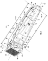
- FIG. 1 is a top perspective view of a hair clipper, according to an exemplary embodiment.
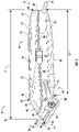
- FIG. 2 is a bottom perspective view of the hair clipper of FIG. 1 .
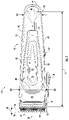
- FIG. 3 is a front side view of the hair clipper of FIG. 1 .
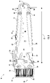
- FIG. 4 is a rear side view of the hair clipper of FIG. 1 .
- FIG. 5 is a right side view of the hair clipper of FIG. 1 .
- FIG. 6 is a left side view of the hair clipper of FIG. 1 .
- FIG. 7 is a top side view of the hair clipper of FIG. 1 .
- FIG. 8 is a bottom side view of the hair clipper of FIG. 1 .
- FIG. 9 is a cross-sectional view of the hair clipper of FIG. 1 .
- Clipper 10 has a handle 12 and a blade assembly 14 .
- Blade assembly 14 includes a cutting upper blade or cutter 16 and a stationary outer or lower blade 18 .
- Oscillating blade/cutter 16 and stationary blade 18 of blade assembly 14 cooperate to cut hair as teeth 20 of cutter 16 oscillate over teeth 20 on stationary blade 18 .
- the teeth 20 on cutter 16 and blade 18 capture hair follicles and cooperate to cut hair.
- FIG. 1 shows a clamshell handle 12 with an upper housing 22 and a lower housing 24 .
- reducing (e.g., tapering) height/width dimensions on handle 12 e.g., along the upper and lower housings 22 and 24
- enhances the balance of the clipper 10 for example, by balancing components in handle 12 to blade assembly 14 .
- the weight of the blade assembly 14 and a motor 26 are coupled near the cutting side or cutting end 28 of handle 12 .
- the weight of motor 26 and blade assembly 14 is offset or balanced in handle 12 by the counterweight provided by a battery 30 at the tapered gripping end 32 of handle 12 .
- width W 1 and/or height H 1 dimensions of clipper 10 enables the motor 26 to be housed within an internal cavity 34 near cutting end 28 , and an elongated battery 30 is captured within internal cavity 34 near the gripping end 32 .
- the width W 3 and/or the height H 3 at gripping end 32 is less than the maximum width W 2 and/or maximum height H 2 at cutting end 28 .
- H 1 and W 1 are used generally to denote a height direction or width direction generally.
- Handle 12 extends along a longitudinal or axial axis 36 that extends from a blade end or cutting end 28 to a handle end or gripping end 32 to define a housing length L 1 .
- a housing width W 1 e.g., between left and right sides of handle 12
- a housing height H 1 e.g., between the top and bottom sides of handle
- a center of gravity 44 for the clipper 10 is more comfortably located within a user's grasp and the size of hair shield 46 is maximized to enhance protection of cavity 34 within handle 12 .
- Handle 12 has width W 1 and height H 1 dimensions extending orthogonally from axial axis 36 .
- handle 12 extends in an arched and/or linear direction along width W 1 and/or height H 1 dimensions, such that at different locations along axial axis 36 , the width W 1 and/or height H 1 , measured in a transverse direction to axial axis 36 , is tapered between cutting end 28 and a rectangular base 48 at gripping end 32 .
- Handle 12 extends between a cutting end 28 and a base 48 at a gripping end 32 of handle 12 .
- a height taper 40 and a width taper 42 measure the relative change between the maximum height H 2 and maximum width W 2 near the cutting end 28 to a base height H 3 and base width W 3 at the base 48 of gripping end 32 .
- the height taper 40 is a dimensionless number that represents a comparison of the height H 1 of handle 12 near the gripping end 32 (e.g., base height H 3 ) divided by the maximum height H 2 of handle 12 .
- the width taper 42 is a dimensionless number that represents a comparison of the width W 1 of handle 12 at the gripping end 32 (e.g., base width W 3 ) divided by the maximum width W 2 of handle 12 .
- rectangular base 48 has base width W 3 between 1 inch and 1.2 inches, specifically between 1.05 inches and 1.15 inches, and a base height between 0.8 inches and 1 inch, specifically between 0.85 inches and 0.95 inches.
- handle 12 is a single, continuous, and/or integral part, such that upper housing 22 and lower housing 24 are permanently joined and/or fabricated as an integral continuous component or unitary part.
- upper housing 22 is fabricated separately from lower housing 24 and joined or coupled to form handle 12 , e.g., using fasteners 49 ( FIG. 2 ).
- a hair shield 46 is formed on the exterior surface 50 of upper housing 22 . Hair shield 46 prevents cut hair or other debris from entering an internal cavity 34 and interfering with rotary motor 26 ( FIG. 9 ). Hair shield 46 captures and/or deflects hair and other debris away from the internal cavity 34 formed by handle 12 and housing rotary motor 26 .
- a rotary motor 26 is captured behind blade assembly 14 at the cutting end 28 between the upper housing 22 and the lower housing 24 .
- a charging port 52 electronically couples to battery 30 within internal cavity 34 .
- Electric charging port 52 is located on a base 48 of handle 12 (e.g., on gripping end 32 ) and is electronically coupled to battery 30 located in gripping end 32 and captured between upper housing 22 and lower housing 24 .
- a side lever 54 is coupled to cutter 16 , and lever 54 rotates to translate cutter blade edge 56 relative to lower/stationary blade edge 58 to increase or decrease a blade gap 60 .
- Rotation of lever 54 changes blade gap 60 between blade edges 56 and 58 in a transverse orthogonal direction by moving cutter 16 a transverse distance.
- Blade gap 60 changes a thickness T 1 of lower blade 18 that cuts hair.
- teeth 20 of cutter 16 generally align with teeth 20 on lower blade 18 , and clipper 10 cuts a shorter length of hair than when blade gap 60 is large or increased.
- the complete thickness T 1 of lower blade 18 is utilized to create a minimum hair length. In this way, lever 54 controls the length of the hair cut by hair clipper 10 .
- a sliding power switch 62 powers clipper 10 and is captured in a recessed perimeter 66 formed between upper housing 22 and lower housing 24 .
- recessed perimeter 66 defines a slot or depth between upper housing 22 and lower housing 24 between 0.025 inches and 0.1 inches, specifically between 0.04 inches and 0.08 inches, and more specifically between 0.05 inches and 0.075 inches.
- Recessed perimeter 66 extends around base 48 , left side 68 , right side 70 , and top side 72 near cutting end 28 of handle 12 .
- recessed perimeter 66 has a length of between 13 inches and 15 inches, specifically, between 13.5 inches and 14.5 inches, and more specifically between 13.75 inches and 14.25 inches.
- Switch 62 is captured between upper housing 22 and lower housing 24 and operates to power cutter 16 on and off.
- switch 62 , upper housing 22 , and/or lower housing 24 are each fabricated from a different material.
- a hook 74 is located on handle 12 near base 48 .
- Hook 74 is located on lower housing 24 and facilitates hanging, storing, and/or gripping handle 12 .
- hook 74 extends between 0.25 inches to 0.5 inches, specifically between 0.3 inches and 0.4 inches, away from base 48 in the direction of axial axis 36 .
- Hair clipper 10 includes enclosed hook 74 extending from either side (e.g., left side 68 and right side 70 ) of base 48 on handle 12 .
- enclosed hook 74 has a width W 1 dimension equal to or greater than 90%, specifically 95%, and more specifically 99%, or more of handle 12 base width W 3 .
- base width W 3 of handle 12 is equal to width W 1 of hook 74 .
- upper housing 22 includes a recess or depression 76 on a top surface or top side 72 of handle 12 .
- Depression 76 forms a gripping pad 78 for a user to place a thumb or fingers while holding handle 12 .
- Depression 76 extends along top side 72 of handle 12 to a projection 80 that defines a maximum height H 2 of handle 12 .
- depression 76 is measured from projection 80 to gripping surface or pad 78 and is between 0.025 inches and 0.1 inches, specifically between 0.06 inches and 0.09 inches, and more specifically, between 0.07 inches and 0.08 inches, in a height H 1 direction on handle 12 .
- Lower housing 24 includes a neck 82 forming a neck gripping recess 84 on a bottom surface or bottom side 86 of handle 12 configured for a user's finger. Finger gripping recess 84 receives the user's finger about neck 82 of blade assembly 14 .
- a gripping depression pad 78 can be located in depression 76 and/or recess 84 of upper housing 22 and/or lower housing 24 .
- neck 82 and/or gripping depression 76 and/or recess 84 are fabricated from a dip molded polymer material.
- FIG. 2 shows a bottom perspective view of hair clipper 10 . From this perspective, height taper 40 and width taper 42 are shown extending away from blade assembly 14 . Blade assembly 14 is coupled to lower housing 24 and extends angularly along lower housing 24 . Stated differently, upper housing 22 extends further in the axial direction than lower housing 24 to create an angled recess 84 in lower housing to capture and/or couple lower housing 24 of handle 12 to blade assembly 14
- Blade 18 is coupled to handle 12 (e.g., upper/lower housing 22 and/or 24 ) and stationary or static.
- cutter 16 oscillates in a direction parallel to blade edges 56 and 58 (e.g., in a direction parallel to the width W 1 of handle 12 ).
- a lever 54 is coupled to cutter 16 to translate cutter 16 along in a direction parallel to axial axis 36 to change a gap 60 between cutter 16 and blade 18 .
- changing the gap 60 between upper and lower blade edges 56 and 58 changes the length of hair that is cut by cutter 16 .
- a shorter gap 60 between the blade edges 56 and 58 enables the combined thicknesses of the cutter 16 and blade 18 to create a longer cut length.
- a longer gap 60 between the blade edges 56 and 58 reduces the combined thickness between the blades and creates a shorter cut length.
- FIGS. 3-9 illustrate different orthogonal views of hair clipper 10 and demonstrate relative and absolute dimensions of clipper 10 to illustrate the shape of height and width tapers 40 and 42 and relationship of handle 12 relative to blade assembly 14 .
- a handle length L 1 is measured along axial axis 36 and defined from a base 48 of handle 12 at the gripping end 32 to a distal end 81 of projection 80 at cutting end 28 .
- a lower housing length L 2 is defined along axial axis 36 from base 48 to a bend 88 at cutting end 28 to couple blade assembly 14 to handle 12 .
- handle length L 1 is between 5 inches and 7 inches, specifically, between 5.5 inches and 6.5 inches, and more specifically, between 5.75 inches and 6.25 inches.
- lower housing length L 2 is between 4 inches and 5.5 inches, specifically between 4.5 inches and 5 inches.
- lower housing length L 2 is 4.75+/ ⁇ 0.05 inches.
- a handle height H 1 is defined in an orthogonal direction to axial axis 36 between a top surface or side 72 and a bottom surface or side 86 of handle 12 .
- a height taper 40 measures the relative change between the maximum height H 2 (near the cutting end 28 ) and the base height H 3 (e.g., measured at the gripping end 32 ).
- height taper 40 is a linear height taper 40 between maximum height H 2 and base height H 3 .
- maximum height H 2 is between 1.0 inches and 1.5 inches, specifically, between 1.2 inches and 1.4 inches, and more specifically, between 1.25 inches and 1.35 inches.
- base height H 3 is between 0.5 inches and 1 inch, specifically, between 0.6 inches and 0.9 inches, and more specifically between 0.7 inches and 0.8 inches.
- Height taper 40 is a relative comparison of maximum height H 2 and base height H 3 .
- Height taper 40 is defined as the reduction ratio or percentage of maximum height H 2 to achieve base height H 3 .
- maximum height H 2 is 1.3 inches
- base height H 3 is 0.8 inches
- height taper 40 is 0.8/1.3 inches (e.g., 0.8:1.3 inches) or approximately 61.5%.
- the maximum height H 2 is between 1.2 inches and 1.4 inches
- base height H 3 is between 0.7 inches and 0.9 inches, such that height taper 40 is between 58% and 62%.
- base height H 3 is between 65% and 75% of base width W 3 , specifically, between 67% and 73%, and more specifically between 69% and 71%.
- a handle width W 1 is defined in an orthogonal direction to axial axis 36 between a left surface or side 68 and a right surface or side 70 of handle 12 .
- a width taper 42 measures the relative change between the maximum width W 2 (near the cutting end 28 ) and the base width W 3 (e.g., measured at the gripping end 32 ).
- width taper 42 is a linear width taper 42 between maximum width W 2 and base width W 3 .
- maximum width W 2 is between 1.3 inches and 1.8 inches, specifically, between 1.4 inches and 1.7 inches, and more specifically, between 1.5 inches and 1.6 inches.
- base width W 3 is between 0.9 inches and 1.3 inches, specifically between 1.0 inch and 1.2 inches, and more specifically between 1.05 inches and 1.15 inches.
- Width taper 42 is a relative comparison of maximum width W 2 and base width W 3 .
- Width taper 42 is defined as the reduction ratio or percentage of maximum width W 2 to achieve base width W 3 .
- width taper 42 is 1.1/1.6 in/in (e.g., 1.1:1.6 in/in) or approximately 68.75%.
- the width taper 42 of 68.75% is greater than the 61.5% height reduction.
- the reduction of width taper 42 is greater than the reduction of height taper 40 .
- maximum width W 2 is between 1.5 inches and 1.7 inches
- base width W 3 is between 1.0 and 1.2 inches, such that width taper is between 70% and 76%.
- width taper 42 When width taper 42 is linear, an angle measure of width taper 42 is made by comparing the angle formed between left side 68 and right side 70 of handle 12 . In various embodiments, width taper 42 is between 7° and 11°, specifically, between 8° and 10°. In a specific embodiment, the width taper 42 defines a 9.4° angle (+/ ⁇ 0.1°).
- the term “coupled” means the joining of two components directly or indirectly to one another. Such joining may be stationary in nature or movable in nature. Such joining may be achieved with the two members and any additional intermediate members being integrally formed as a single unitary body with one another or with the two members or the two members and any additional member being attached to one another. Such joining may be permanent in nature or alternatively may be removable or releasable in nature.
- the relative dimensions, including angles, lengths, and radii, are to scale as shown in the Figures.
- the figures' actual measurements will disclose relative dimensions, angles, and proportions of the various exemplary embodiments.
- Various exemplary embodiments extend to various ranges around the absolute and relative dimensions, angles, and proportions that may be determined from the Figures.
- Various exemplary embodiments include any combination of one or more relative dimensions or angles that may be determined from the Figures.
- actual dimensions not expressly set out in this description can be determined by using the ratios of dimensions measured in the Figures in combination with the express dimensions set out in this description.
- the present disclosure extends to a variety of ranges (e.g., plus or minus 30%, 20%, or 10%) around any of the absolute or relative dimensions disclosed herein or determinable from the Figures.
Landscapes
- Life Sciences & Earth Sciences (AREA)
- Forests & Forestry (AREA)
- Engineering & Computer Science (AREA)
- Mechanical Engineering (AREA)
- Dry Shavers And Clippers (AREA)
Abstract
Description
- This application is a Continuation-in-Part of U.S. Design application No. 29/761,651, filed Dec. 10, 2020, which is incorporated herein by reference in its entirety.
- The present invention relates generally to the field of haircutters or clippers. The present invention relates specifically to hair clippers with a modified balanced housing.
- One embodiment of the invention relates to a haircutter having a blade assembly and a handle. The blade assembly defines a cutting end with a stationary blade and an oscillating blade that oscillates cutting teeth over the stationary blade to cut hair. The handle has a rectangular base at a gripping end opposite the blade assembly. The user grasps the gripping end to operate the haircutter. The handle defines a height taper and a width taper. The reduction from a maximum height of the handle to a base height defines the height taper. The reduction from a maximum width of the handle to a base width defines the width taper. The width taper is greater than the height taper, such that the handle width reduces more than the handle height.
- Another embodiment of the invention relates to a haircutter having a handle coupled to a blade assembly. The handle having a first end defining a first width and a first height. Similarly, a second end opposite the first end defines a second width and a second height. The handle has a taper, such that the first width and first height are greater than the second width and second height. The handle further includes a rectangular base with a first base width and a first base height. The blade assembly is coupled to the handle at the first end and includes a first blade and a second blade. The first blade having oscillating teeth extending along a first blade edge. The second blade having teeth extending along a second blade edge that is orientated parallel to the first blade edge. A distance between the first and second blade edges defines a blade gap. A side lever is coupled to the first blade to move the first blade edge relative to the second blade edge adjusting the blade gap. Increasing or decreasing the blade gap adjusts the length of hair cut by the blade assembly.
- Another embodiment of the invention relates to a haircutter having a clamshell handle coupled to a blade assembly. The clamshell handle has an upper housing and a lower housing that extend axially between a cutting end and a rectangular base at a gripping end opposite the cutting end. The upper housing includes a hair shield defined by an upward sloped portion proximate the cutting end such that hair is deflected away from the blade assembly. The lower housing is coupled to the upper housing forming a recessed perimeter between the upper and lower housing. The recessed perimeter includes a switch. The upper and lower housing together define a tapered handle having a width at the cutting end that is greater than a width at the base. The reduction of the handle width defines a width taper. Similarly, a height at the cutting end is greater than a height at the base. The reduction of the handle height defines a height taper. The width taper of the handle is greater than the height taper. The blade assembly is coupled to the cutting end of the handle and includes a first blade and a second blade. The first blade having oscillating teeth extending along a first blade edge. The second blade having teeth extending along a second blade edge that is orientated parallel to the first blade edge. A distance between the first and second blade edges defines a blade gap. A lever is coupled to the first blade to move the first blade edge relative to the second blade edge adjusting the blade gap. Increasing or decreasing the blade gap adjusts the length of hair cut by the blade assembly.
- Alternative exemplary embodiments relate to other features and combinations of features as may be generally recited in the claims.
- This application will become more fully understood from the following detailed description, taken in conjunction with the accompanying figures, wherein like reference numerals refer to like elements in which:
-
FIG. 1 is a top perspective view of a hair clipper, according to an exemplary embodiment. -
FIG. 2 is a bottom perspective view of the hair clipper ofFIG. 1 . -
FIG. 3 is a front side view of the hair clipper ofFIG. 1 . -
FIG. 4 is a rear side view of the hair clipper ofFIG. 1 . -
FIG. 5 is a right side view of the hair clipper ofFIG. 1 . -
FIG. 6 is a left side view of the hair clipper ofFIG. 1 . -
FIG. 7 is a top side view of the hair clipper ofFIG. 1 . -
FIG. 8 is a bottom side view of the hair clipper ofFIG. 1 . -
FIG. 9 is a cross-sectional view of the hair clipper ofFIG. 1 . - Referring to
FIG. 1 , a hair trimmer, clipper, orclipper 10 is shown. Clipper 10 has ahandle 12 and ablade assembly 14.Blade assembly 14 includes a cutting upper blade orcutter 16 and a stationary outer orlower blade 18. Oscillating blade/cutter 16 andstationary blade 18 ofblade assembly 14 cooperate to cut hair asteeth 20 ofcutter 16 oscillate overteeth 20 onstationary blade 18. Specifically, ascutter 16 oscillates overstationary blade 18, theteeth 20 oncutter 16 andblade 18 capture hair follicles and cooperate to cut hair. -
FIG. 1 shows aclamshell handle 12 with anupper housing 22 and alower housing 24. Applicant has found that reducing (e.g., tapering) height/width dimensions on handle 12 (e.g., along the upper andlower housings 22 and 24) enhances the balance of theclipper 10, for example, by balancing components inhandle 12 toblade assembly 14. Specifically as shown inFIG. 9 , the weight of theblade assembly 14 and amotor 26 are coupled near the cutting side or cuttingend 28 ofhandle 12. The weight ofmotor 26 andblade assembly 14 is offset or balanced inhandle 12 by the counterweight provided by abattery 30 at thetapered gripping end 32 ofhandle 12. Specifically, reducing or tapering the width W1 and/or height H1 dimensions ofclipper 10 enables themotor 26 to be housed within aninternal cavity 34 nearcutting end 28, and anelongated battery 30 is captured withininternal cavity 34 near the grippingend 32. For example, the width W3 and/or the height H3 at grippingend 32 is less than the maximum width W2 and/or maximum height H2 at cuttingend 28. As used herein, H1 and W1 are used generally to denote a height direction or width direction generally. -
Handle 12 extends along a longitudinal oraxial axis 36 that extends from a blade end or cuttingend 28 to a handle end orgripping end 32 to define a housing length L1. At an orthogonal or perpendicular angle toaxial axis 36, a housing width W1 (e.g., between left and right sides of handle 12) and a housing height H1 (e.g., between the top and bottom sides of handle) are defined. Applicant has found that by including aheight taper 40 and awidth taper 42, or specifically a reduction in height H1 and width W1 dimensions alongaxial axis 36, a center ofgravity 44 for theclipper 10 is more comfortably located within a user's grasp and the size ofhair shield 46 is maximized to enhance protection ofcavity 34 withinhandle 12. -
Handle 12 has width W1 and height H1 dimensions extending orthogonally fromaxial axis 36. In various embodiments, handle 12 extends in an arched and/or linear direction along width W1 and/or height H1 dimensions, such that at different locations alongaxial axis 36, the width W1 and/or height H1, measured in a transverse direction toaxial axis 36, is tapered between cuttingend 28 and arectangular base 48 at grippingend 32. -
Handle 12 extends between a cuttingend 28 and a base 48 at agripping end 32 ofhandle 12. Aheight taper 40 and awidth taper 42 measure the relative change between the maximum height H2 and maximum width W2 near the cuttingend 28 to a base height H3 and base width W3 at thebase 48 of grippingend 32. Specifically, theheight taper 40 is a dimensionless number that represents a comparison of the height H1 ofhandle 12 near the gripping end 32 (e.g., base height H3) divided by the maximum height H2 ofhandle 12. Similarly, thewidth taper 42 is a dimensionless number that represents a comparison of the width W1 ofhandle 12 at the gripping end 32 (e.g., base width W3) divided by the maximum width W2 ofhandle 12. In various embodiments,rectangular base 48 has base width W3 between 1 inch and 1.2 inches, specifically between 1.05 inches and 1.15 inches, and a base height between 0.8 inches and 1 inch, specifically between 0.85 inches and 0.95 inches. - In various embodiments, handle 12 is a single, continuous, and/or integral part, such that
upper housing 22 andlower housing 24 are permanently joined and/or fabricated as an integral continuous component or unitary part. In other embodiments,upper housing 22 is fabricated separately fromlower housing 24 and joined or coupled to form handle 12, e.g., using fasteners 49 (FIG. 2 ). Ahair shield 46 is formed on theexterior surface 50 ofupper housing 22.Hair shield 46 prevents cut hair or other debris from entering aninternal cavity 34 and interfering with rotary motor 26 (FIG. 9 ).Hair shield 46 captures and/or deflects hair and other debris away from theinternal cavity 34 formed byhandle 12 andhousing rotary motor 26. For example, arotary motor 26 is captured behindblade assembly 14 at the cuttingend 28 between theupper housing 22 and thelower housing 24. At the opposite end, or handlegripping end 32, a chargingport 52 electronically couples tobattery 30 withininternal cavity 34. Electric chargingport 52 is located on abase 48 of handle 12 (e.g., on gripping end 32) and is electronically coupled tobattery 30 located ingripping end 32 and captured betweenupper housing 22 andlower housing 24. - In one embodiment, a
side lever 54 is coupled tocutter 16, andlever 54 rotates to translatecutter blade edge 56 relative to lower/stationary blade edge 58 to increase or decrease ablade gap 60. Rotation oflever 54changes blade gap 60 between blade edges 56 and 58 in a transverse orthogonal direction by moving cutter 16 a transverse distance.Blade gap 60 changes a thickness T1 oflower blade 18 that cuts hair. For example, whenblade gap 60 is small,teeth 20 ofcutter 16 generally align withteeth 20 onlower blade 18, andclipper 10 cuts a shorter length of hair than whenblade gap 60 is large or increased. Specifically, when theblade gap 60 is large, the complete thickness T1 oflower blade 18 is utilized to create a minimum hair length. In this way,lever 54 controls the length of the hair cut byhair clipper 10. - As shown in
FIGS. 1 and 2 , a slidingpower switch 62powers clipper 10 and is captured in a recessedperimeter 66 formed betweenupper housing 22 andlower housing 24. In various embodiments, recessedperimeter 66 defines a slot or depth betweenupper housing 22 andlower housing 24 between 0.025 inches and 0.1 inches, specifically between 0.04 inches and 0.08 inches, and more specifically between 0.05 inches and 0.075 inches. Recessedperimeter 66 extends aroundbase 48,left side 68,right side 70, andtop side 72 near cuttingend 28 ofhandle 12. In various embodiments, recessedperimeter 66 has a length of between 13 inches and 15 inches, specifically, between 13.5 inches and 14.5 inches, and more specifically between 13.75 inches and 14.25 inches. -
Side switch 62 is captured betweenupper housing 22 andlower housing 24 and operates topower cutter 16 on and off. In various embodiments,switch 62,upper housing 22, and/orlower housing 24 are each fabricated from a different material. - A
hook 74 is located onhandle 12 nearbase 48.Hook 74 is located onlower housing 24 and facilitates hanging, storing, and/or grippinghandle 12. In various embodiments,hook 74 extends between 0.25 inches to 0.5 inches, specifically between 0.3 inches and 0.4 inches, away frombase 48 in the direction ofaxial axis 36.Hair clipper 10 includes enclosedhook 74 extending from either side (e.g.,left side 68 and right side 70) ofbase 48 onhandle 12. In various embodiments, enclosedhook 74 has a width W1 dimension equal to or greater than 90%, specifically 95%, and more specifically 99%, or more ofhandle 12 base width W3. In one embodiment, base width W3 ofhandle 12 is equal to width W1 ofhook 74. - In various embodiments,
upper housing 22 includes a recess ordepression 76 on a top surface ortop side 72 ofhandle 12.Depression 76 forms agripping pad 78 for a user to place a thumb or fingers while holdinghandle 12.Depression 76 extends alongtop side 72 ofhandle 12 to aprojection 80 that defines a maximum height H2 ofhandle 12. In various embodiments,depression 76 is measured fromprojection 80 to gripping surface orpad 78 and is between 0.025 inches and 0.1 inches, specifically between 0.06 inches and 0.09 inches, and more specifically, between 0.07 inches and 0.08 inches, in a height H1 direction onhandle 12. -
Lower housing 24 includes aneck 82 forming aneck gripping recess 84 on a bottom surface orbottom side 86 ofhandle 12 configured for a user's finger.Finger gripping recess 84 receives the user's finger aboutneck 82 ofblade assembly 14. A grippingdepression pad 78 can be located indepression 76 and/orrecess 84 ofupper housing 22 and/orlower housing 24. For example,neck 82 and/or grippingdepression 76 and/orrecess 84 are fabricated from a dip molded polymer material. -
FIG. 2 shows a bottom perspective view ofhair clipper 10. From this perspective,height taper 40 andwidth taper 42 are shown extending away fromblade assembly 14.Blade assembly 14 is coupled tolower housing 24 and extends angularly alonglower housing 24. Stated differently,upper housing 22 extends further in the axial direction thanlower housing 24 to create anangled recess 84 in lower housing to capture and/or couplelower housing 24 ofhandle 12 toblade assembly 14 -
Blade 18 is coupled to handle 12 (e.g., upper/lower housing 22 and/or 24) and stationary or static. In contrast,cutter 16 oscillates in a direction parallel to blade edges 56 and 58 (e.g., in a direction parallel to the width W1 of handle 12). As described in greater detail below, alever 54 is coupled tocutter 16 to translatecutter 16 along in a direction parallel toaxial axis 36 to change agap 60 betweencutter 16 andblade 18. For example, changing thegap 60 between upper and lower blade edges 56 and 58 changes the length of hair that is cut bycutter 16. Specifically, ashorter gap 60 between the blade edges 56 and 58 enables the combined thicknesses of thecutter 16 andblade 18 to create a longer cut length. Similarly, alonger gap 60 between the blade edges 56 and 58 reduces the combined thickness between the blades and creates a shorter cut length. -
FIGS. 3-9 illustrate different orthogonal views ofhair clipper 10 and demonstrate relative and absolute dimensions ofclipper 10 to illustrate the shape of height and width tapers 40 and 42 and relationship ofhandle 12 relative toblade assembly 14. A handle length L1 is measured alongaxial axis 36 and defined from abase 48 ofhandle 12 at thegripping end 32 to adistal end 81 ofprojection 80 at cuttingend 28. Similarly, a lower housing length L2 is defined alongaxial axis 36 frombase 48 to abend 88 at cuttingend 28 to coupleblade assembly 14 to handle 12. In various embodiments, handle length L1 is between 5 inches and 7 inches, specifically, between 5.5 inches and 6.5 inches, and more specifically, between 5.75 inches and 6.25 inches. In various embodiments, lower housing length L2 is between 4 inches and 5.5 inches, specifically between 4.5 inches and 5 inches. In one embodiment, lower housing length L2 is 4.75+/−0.05 inches. - Similarly, a handle height H1 is defined in an orthogonal direction to
axial axis 36 between a top surface orside 72 and a bottom surface orside 86 ofhandle 12. Aheight taper 40 measures the relative change between the maximum height H2 (near the cutting end 28) and the base height H3 (e.g., measured at the gripping end 32). In one embodiment,height taper 40 is alinear height taper 40 between maximum height H2 and base height H3. In various embodiments, maximum height H2 is between 1.0 inches and 1.5 inches, specifically, between 1.2 inches and 1.4 inches, and more specifically, between 1.25 inches and 1.35 inches. In various embodiments, base height H3 is between 0.5 inches and 1 inch, specifically, between 0.6 inches and 0.9 inches, and more specifically between 0.7 inches and 0.8 inches. -
Height taper 40 is a relative comparison of maximum height H2 and base height H3.Height taper 40 is defined as the reduction ratio or percentage of maximum height H2 to achieve base height H3. As a specific example, when maximum height H2 is 1.3 inches, and base height H3 is 0.8 inches,height taper 40 is 0.8/1.3 inches (e.g., 0.8:1.3 inches) or approximately 61.5%. In various embodiments, the maximum height H2 is between 1.2 inches and 1.4 inches, and base height H3 is between 0.7 inches and 0.9 inches, such thatheight taper 40 is between 58% and 62%. In various embodiments, base height H3 is between 65% and 75% of base width W3, specifically, between 67% and 73%, and more specifically between 69% and 71%. - Similarly, a handle width W1 is defined in an orthogonal direction to
axial axis 36 between a left surface orside 68 and a right surface orside 70 ofhandle 12. Awidth taper 42 measures the relative change between the maximum width W2 (near the cutting end 28) and the base width W3 (e.g., measured at the gripping end 32). In one embodiment,width taper 42 is alinear width taper 42 between maximum width W2 and base width W3. In various embodiments, maximum width W2 is between 1.3 inches and 1.8 inches, specifically, between 1.4 inches and 1.7 inches, and more specifically, between 1.5 inches and 1.6 inches. In various embodiments, base width W3 is between 0.9 inches and 1.3 inches, specifically between 1.0 inch and 1.2 inches, and more specifically between 1.05 inches and 1.15 inches. -
Width taper 42 is a relative comparison of maximum width W2 and base width W3.Width taper 42 is defined as the reduction ratio or percentage of maximum width W2 to achieve base width W3. As a specific example, when maximum width W2 is 1.6 inches and base width W3 is 1.1 inches,width taper 42 is 1.1/1.6 in/in (e.g., 1.1:1.6 in/in) or approximately 68.75%. Compared to the previous height example with aheight taper 40 of 61.5%, thewidth taper 42 of 68.75% is greater than the 61.5% height reduction. In other words, the reduction ofwidth taper 42 is greater than the reduction ofheight taper 40. In various embodiments, maximum width W2 is between 1.5 inches and 1.7 inches, and base width W3 is between 1.0 and 1.2 inches, such that width taper is between 70% and 76%. - When
width taper 42 is linear, an angle measure ofwidth taper 42 is made by comparing the angle formed betweenleft side 68 andright side 70 ofhandle 12. In various embodiments,width taper 42 is between 7° and 11°, specifically, between 8° and 10°. In a specific embodiment, thewidth taper 42 defines a 9.4° angle (+/−0.1°). - It should be understood that the figures illustrate the exemplary embodiments in detail, and it should be understood that the present application is not limited to the details or methodology set forth in the description or illustrated in the figures. It should also be understood that the terminology is for the purpose of description only and should not be regarded as limiting.
- Further modifications and alternative embodiments of various aspects of the invention will be apparent to those skilled in the art in view of this description. Accordingly, this description is to be construed as illustrative only. The construction and arrangements, shown in the various exemplary embodiments, are illustrative only. Although only a few embodiments have been described in detail in this disclosure, many modifications are possible (e.g., variations in sizes, dimensions, structures, shapes and proportions of the various elements, values of parameters, mounting arrangements, use of materials, colors, orientations, etc.) without materially departing from the novel teachings and advantages of the subject matter described herein. Some elements shown as integrally formed may be constructed of multiple parts or elements, the position of elements may be reversed or otherwise varied, and the nature or number of discrete elements or positions may be altered or varied. Other substitutions, modifications, changes, and omissions may also be made in the design, operating conditions, and arrangement of the various exemplary embodiments without departing from the present invention's scope.
- For purposes of this disclosure, the term “coupled” means the joining of two components directly or indirectly to one another. Such joining may be stationary in nature or movable in nature. Such joining may be achieved with the two members and any additional intermediate members being integrally formed as a single unitary body with one another or with the two members or the two members and any additional member being attached to one another. Such joining may be permanent in nature or alternatively may be removable or releasable in nature.
- In various exemplary embodiments, the relative dimensions, including angles, lengths, and radii, are to scale as shown in the Figures. The figures' actual measurements will disclose relative dimensions, angles, and proportions of the various exemplary embodiments. Various exemplary embodiments extend to various ranges around the absolute and relative dimensions, angles, and proportions that may be determined from the Figures. Various exemplary embodiments include any combination of one or more relative dimensions or angles that may be determined from the Figures. Further, actual dimensions not expressly set out in this description can be determined by using the ratios of dimensions measured in the Figures in combination with the express dimensions set out in this description. In addition, in various embodiments, the present disclosure extends to a variety of ranges (e.g., plus or minus 30%, 20%, or 10%) around any of the absolute or relative dimensions disclosed herein or determinable from the Figures.
Claims (20)
Priority Applications (1)
| Application Number | Priority Date | Filing Date | Title |
|---|---|---|---|
| US17/318,676 US20220184832A1 (en) | 2020-12-10 | 2021-05-12 | Hair Clipper with Tapered Rectangular Handle |
Applications Claiming Priority (2)
| Application Number | Priority Date | Filing Date | Title |
|---|---|---|---|
| US29/761,651 USD972217S1 (en) | 2020-12-10 | 2020-12-10 | Hair clipper |
| US17/318,676 US20220184832A1 (en) | 2020-12-10 | 2021-05-12 | Hair Clipper with Tapered Rectangular Handle |
Related Parent Applications (1)
| Application Number | Title | Priority Date | Filing Date |
|---|---|---|---|
| US29/761,651 Continuation-In-Part USD972217S1 (en) | 2020-12-10 | 2020-12-10 | Hair clipper |
Publications (1)
| Publication Number | Publication Date |
|---|---|
| US20220184832A1 true US20220184832A1 (en) | 2022-06-16 |
Family
ID=81943203
Family Applications (1)
| Application Number | Title | Priority Date | Filing Date |
|---|---|---|---|
| US17/318,676 Abandoned US20220184832A1 (en) | 2020-12-10 | 2021-05-12 | Hair Clipper with Tapered Rectangular Handle |
Country Status (1)
| Country | Link |
|---|---|
| US (1) | US20220184832A1 (en) |
Cited By (11)
| Publication number | Priority date | Publication date | Assignee | Title |
|---|---|---|---|---|
| USD980530S1 (en) * | 2021-06-04 | 2023-03-07 | Conair Llc | Hair clipper |
| USD991560S1 (en) * | 2023-04-12 | 2023-07-04 | Ningbo HomeBeauty Electrical Appliances Co., Ltd | Electric clipper |
| USD1005590S1 (en) * | 2023-04-19 | 2023-11-21 | Hanjie Zhang | Electric clipper |
| USD1007055S1 (en) * | 2023-04-19 | 2023-12-05 | Nature Lab Corporation | Electric hair clipper |
| USD1017903S1 (en) * | 2023-04-24 | 2024-03-12 | Hanjie Zhang | Electric clipper |
| USD1018989S1 (en) * | 2023-04-19 | 2024-03-19 | Hanjie Zhang | Electric clipper |
| USD1021252S1 (en) * | 2023-09-28 | 2024-04-02 | Lu Zhang | Electric clipper |
| USD1028361S1 (en) * | 2023-04-24 | 2024-05-21 | Hanjie Zhang | Electric clipper |
| USD1033746S1 (en) * | 2023-09-28 | 2024-07-02 | Lu Zhang | Electric clipper |
| USD1035152S1 (en) * | 2023-11-09 | 2024-07-09 | Yiwu Lehman Electronic Technology Co., Ltd. | Hair trimmer |
| EP4484088A1 (en) * | 2023-06-30 | 2025-01-01 | Braun GmbH | System comprising a personal care device such as electric shaver and hanger for such device |
Citations (9)
| Publication number | Priority date | Publication date | Assignee | Title |
|---|---|---|---|---|
| US1474128A (en) * | 1922-09-22 | 1923-11-13 | Leo J Wahl | Electric clipper |
| US1671265A (en) * | 1926-06-26 | 1928-05-29 | Andis Mathew | Electrically-driven hair clipper |
| US2502036A (en) * | 1946-12-09 | 1950-03-28 | Earle E Dietrich | Electric shaver |
| US3157804A (en) * | 1961-09-12 | 1964-11-17 | Goodwin Mfg & Dev Company Inc | Razor motor and casing therefor |
| US20110010943A1 (en) * | 2009-07-17 | 2011-01-20 | Izumi Products Company | Electric shaver |
| US8341846B1 (en) * | 2008-11-24 | 2013-01-01 | Lonnie Holmes | Hair clippers with electrically adjustable blades |
| USD681276S1 (en) * | 2011-10-27 | 2013-04-30 | Wahl Gmbh | Hair clipper |
| US9266245B2 (en) * | 2012-01-12 | 2016-02-23 | Spectrum Brands, Inc. | Electric hair trimmer |
| US20180333876A1 (en) * | 2015-01-28 | 2018-11-22 | Koninklijke Philips N.V | Hair clipping device |
-
2021
- 2021-05-12 US US17/318,676 patent/US20220184832A1/en not_active Abandoned
Patent Citations (10)
| Publication number | Priority date | Publication date | Assignee | Title |
|---|---|---|---|---|
| US1474128A (en) * | 1922-09-22 | 1923-11-13 | Leo J Wahl | Electric clipper |
| US1671265A (en) * | 1926-06-26 | 1928-05-29 | Andis Mathew | Electrically-driven hair clipper |
| US2502036A (en) * | 1946-12-09 | 1950-03-28 | Earle E Dietrich | Electric shaver |
| US3157804A (en) * | 1961-09-12 | 1964-11-17 | Goodwin Mfg & Dev Company Inc | Razor motor and casing therefor |
| US8341846B1 (en) * | 2008-11-24 | 2013-01-01 | Lonnie Holmes | Hair clippers with electrically adjustable blades |
| US9352476B1 (en) * | 2008-11-24 | 2016-05-31 | Lonnie Holmes | Hair clippers with electrically adjustable blades |
| US20110010943A1 (en) * | 2009-07-17 | 2011-01-20 | Izumi Products Company | Electric shaver |
| USD681276S1 (en) * | 2011-10-27 | 2013-04-30 | Wahl Gmbh | Hair clipper |
| US9266245B2 (en) * | 2012-01-12 | 2016-02-23 | Spectrum Brands, Inc. | Electric hair trimmer |
| US20180333876A1 (en) * | 2015-01-28 | 2018-11-22 | Koninklijke Philips N.V | Hair clipping device |
Cited By (12)
| Publication number | Priority date | Publication date | Assignee | Title |
|---|---|---|---|---|
| USD980530S1 (en) * | 2021-06-04 | 2023-03-07 | Conair Llc | Hair clipper |
| USD991560S1 (en) * | 2023-04-12 | 2023-07-04 | Ningbo HomeBeauty Electrical Appliances Co., Ltd | Electric clipper |
| USD1005590S1 (en) * | 2023-04-19 | 2023-11-21 | Hanjie Zhang | Electric clipper |
| USD1007055S1 (en) * | 2023-04-19 | 2023-12-05 | Nature Lab Corporation | Electric hair clipper |
| USD1018989S1 (en) * | 2023-04-19 | 2024-03-19 | Hanjie Zhang | Electric clipper |
| USD1017903S1 (en) * | 2023-04-24 | 2024-03-12 | Hanjie Zhang | Electric clipper |
| USD1028361S1 (en) * | 2023-04-24 | 2024-05-21 | Hanjie Zhang | Electric clipper |
| EP4484088A1 (en) * | 2023-06-30 | 2025-01-01 | Braun GmbH | System comprising a personal care device such as electric shaver and hanger for such device |
| WO2025003944A1 (en) * | 2023-06-30 | 2025-01-02 | Braun Gmbh | System comprising a personal care device such as electric shaver and hanger for such device |
| USD1021252S1 (en) * | 2023-09-28 | 2024-04-02 | Lu Zhang | Electric clipper |
| USD1033746S1 (en) * | 2023-09-28 | 2024-07-02 | Lu Zhang | Electric clipper |
| USD1035152S1 (en) * | 2023-11-09 | 2024-07-09 | Yiwu Lehman Electronic Technology Co., Ltd. | Hair trimmer |
Similar Documents
| Publication | Publication Date | Title |
|---|---|---|
| US20220184832A1 (en) | Hair Clipper with Tapered Rectangular Handle | |
| US11602865B2 (en) | Hair clipper with tapered radial handle | |
| US8176637B2 (en) | Hair clipper | |
| US7762001B2 (en) | Hair clipper | |
| US10850411B2 (en) | Haircutter and haircutting blade | |
| EP4032668B1 (en) | Electric handheld hair trimmer with blade guard | |
| US20210394376A1 (en) | Hair Clipper with Improved Housing | |
| JP6110572B2 (en) | Cutting head and hair cutting instrument | |
| CA2616429C (en) | Hair trimmer with rotatable detented head | |
| US10005192B2 (en) | Electric hair clipper | |
| US20130212885A1 (en) | Electric head shaver | |
| US20170120466A1 (en) | Coupling mechanism for a drive train of a hair cutting appliance | |
| US20200101632A1 (en) | Safety Cutter | |
| JP2010004992A (en) | Hair clipper blade and electric hair clippers | |
| CN101553346A (en) | Handheld Power Tools | |
| US12502796B2 (en) | Hair clipper with blade assembly having entrapped spring | |
| AU2014304753A1 (en) | Electric hair clipper | |
| CN101443166B (en) | Portable power tool having a tool driven in an oscillating and pendulous manner | |
| CN115298003A (en) | Hair clipper with pivoting blade set for enhanced user visibility | |
| US20020152618A1 (en) | Handle mounting arrangement for a power tool | |
| JP7165430B2 (en) | Hair cutters and hair cutting blades | |
| JP3593714B2 (en) | Eyebrow razor | |
| US20250296257A1 (en) | Haircutter and haircutting blade | |
| CN218802407U (en) | Portable hair cutting device | |
| EP4501560A1 (en) | Blade unit and electric razor |
Legal Events
| Date | Code | Title | Description |
|---|---|---|---|
| STPP | Information on status: patent application and granting procedure in general |
Free format text: NON FINAL ACTION MAILED |
|
| STPP | Information on status: patent application and granting procedure in general |
Free format text: RESPONSE TO NON-FINAL OFFICE ACTION ENTERED AND FORWARDED TO EXAMINER |
|
| STPP | Information on status: patent application and granting procedure in general |
Free format text: FINAL REJECTION MAILED |
|
| STPP | Information on status: patent application and granting procedure in general |
Free format text: DOCKETED NEW CASE - READY FOR EXAMINATION |
|
| STPP | Information on status: patent application and granting procedure in general |
Free format text: NON FINAL ACTION MAILED |
|
| STPP | Information on status: patent application and granting procedure in general |
Free format text: RESPONSE TO NON-FINAL OFFICE ACTION ENTERED AND FORWARDED TO EXAMINER |
|
| STPP | Information on status: patent application and granting procedure in general |
Free format text: FINAL REJECTION MAILED |
|
| STPP | Information on status: patent application and granting procedure in general |
Free format text: RESPONSE AFTER FINAL ACTION FORWARDED TO EXAMINER |
|
| STPP | Information on status: patent application and granting procedure in general |
Free format text: ADVISORY ACTION MAILED |
|
| STCB | Information on status: application discontinuation |
Free format text: ABANDONED -- FAILURE TO RESPOND TO AN OFFICE ACTION |