US20220184816A1 - Packaging plant - Google Patents
Packaging plant Download PDFInfo
- Publication number
- US20220184816A1 US20220184816A1 US17/549,374 US202117549374A US2022184816A1 US 20220184816 A1 US20220184816 A1 US 20220184816A1 US 202117549374 A US202117549374 A US 202117549374A US 2022184816 A1 US2022184816 A1 US 2022184816A1
- Authority
- US
- United States
- Prior art keywords
- transport truck
- robot
- packaging
- packaging plant
- guide rail
- Prior art date
- Legal status (The legal status is an assumption and is not a legal conclusion. Google has not performed a legal analysis and makes no representation as to the accuracy of the status listed.)
- Abandoned
Links
Images


Classifications
-
- B—PERFORMING OPERATIONS; TRANSPORTING
- B65—CONVEYING; PACKING; STORING; HANDLING THIN OR FILAMENTARY MATERIAL
- B65B—MACHINES, APPARATUS OR DEVICES FOR, OR METHODS OF, PACKAGING ARTICLES OR MATERIALS; UNPACKING
- B65B35/00—Supplying, feeding, arranging or orientating articles to be packaged
- B65B35/10—Feeding, e.g. conveying, single articles
- B65B35/16—Feeding, e.g. conveying, single articles by grippers
-
- B—PERFORMING OPERATIONS; TRANSPORTING
- B65—CONVEYING; PACKING; STORING; HANDLING THIN OR FILAMENTARY MATERIAL
- B65B—MACHINES, APPARATUS OR DEVICES FOR, OR METHODS OF, PACKAGING ARTICLES OR MATERIALS; UNPACKING
- B65B17/00—Other machines, apparatus, or methods for packaging articles or materials
-
- B—PERFORMING OPERATIONS; TRANSPORTING
- B25—HAND TOOLS; PORTABLE POWER-DRIVEN TOOLS; MANIPULATORS
- B25J—MANIPULATORS; CHAMBERS PROVIDED WITH MANIPULATION DEVICES
- B25J11/00—Manipulators not otherwise provided for
-
- B—PERFORMING OPERATIONS; TRANSPORTING
- B25—HAND TOOLS; PORTABLE POWER-DRIVEN TOOLS; MANIPULATORS
- B25J—MANIPULATORS; CHAMBERS PROVIDED WITH MANIPULATION DEVICES
- B25J13/00—Controls for manipulators
- B25J13/006—Controls for manipulators by means of a wireless system for controlling one or several manipulators
-
- B—PERFORMING OPERATIONS; TRANSPORTING
- B25—HAND TOOLS; PORTABLE POWER-DRIVEN TOOLS; MANIPULATORS
- B25J—MANIPULATORS; CHAMBERS PROVIDED WITH MANIPULATION DEVICES
- B25J13/00—Controls for manipulators
- B25J13/08—Controls for manipulators by means of sensing devices, e.g. viewing or touching devices
-
- B—PERFORMING OPERATIONS; TRANSPORTING
- B25—HAND TOOLS; PORTABLE POWER-DRIVEN TOOLS; MANIPULATORS
- B25J—MANIPULATORS; CHAMBERS PROVIDED WITH MANIPULATION DEVICES
- B25J19/00—Accessories fitted to manipulators, e.g. for monitoring, for viewing; Safety devices combined with or specially adapted for use in connection with manipulators
- B25J19/0025—Means for supplying energy to the end effector
-
- B—PERFORMING OPERATIONS; TRANSPORTING
- B25—HAND TOOLS; PORTABLE POWER-DRIVEN TOOLS; MANIPULATORS
- B25J—MANIPULATORS; CHAMBERS PROVIDED WITH MANIPULATION DEVICES
- B25J21/00—Chambers provided with manipulation devices
- B25J21/005—Clean rooms
-
- B—PERFORMING OPERATIONS; TRANSPORTING
- B25—HAND TOOLS; PORTABLE POWER-DRIVEN TOOLS; MANIPULATORS
- B25J—MANIPULATORS; CHAMBERS PROVIDED WITH MANIPULATION DEVICES
- B25J5/00—Manipulators mounted on wheels or on carriages
- B25J5/007—Manipulators mounted on wheels or on carriages mounted on wheels
-
- B—PERFORMING OPERATIONS; TRANSPORTING
- B25—HAND TOOLS; PORTABLE POWER-DRIVEN TOOLS; MANIPULATORS
- B25J—MANIPULATORS; CHAMBERS PROVIDED WITH MANIPULATION DEVICES
- B25J5/00—Manipulators mounted on wheels or on carriages
- B25J5/02—Manipulators mounted on wheels or on carriages travelling along a guideway
-
- B—PERFORMING OPERATIONS; TRANSPORTING
- B25—HAND TOOLS; PORTABLE POWER-DRIVEN TOOLS; MANIPULATORS
- B25J—MANIPULATORS; CHAMBERS PROVIDED WITH MANIPULATION DEVICES
- B25J9/00—Program-controlled manipulators
- B25J9/10—Program-controlled manipulators characterised by positioning means for manipulator elements
- B25J9/14—Program-controlled manipulators characterised by positioning means for manipulator elements fluid
-
- B—PERFORMING OPERATIONS; TRANSPORTING
- B60—VEHICLES IN GENERAL
- B60L—PROPULSION OF ELECTRICALLY-PROPELLED VEHICLES; SUPPLYING ELECTRIC POWER FOR AUXILIARY EQUIPMENT OF ELECTRICALLY-PROPELLED VEHICLES; ELECTRODYNAMIC BRAKE SYSTEMS FOR VEHICLES IN GENERAL; MAGNETIC SUSPENSION OR LEVITATION FOR VEHICLES; MONITORING OPERATING VARIABLES OF ELECTRICALLY-PROPELLED VEHICLES; ELECTRIC SAFETY DEVICES FOR ELECTRICALLY-PROPELLED VEHICLES
- B60L5/00—Current collectors for power supply lines of electrically-propelled vehicles
- B60L5/38—Current collectors for power supply lines of electrically-propelled vehicles for collecting current from conductor rails
- B60L5/39—Current collectors for power supply lines of electrically-propelled vehicles for collecting current from conductor rails from third rail
-
- B—PERFORMING OPERATIONS; TRANSPORTING
- B65—CONVEYING; PACKING; STORING; HANDLING THIN OR FILAMENTARY MATERIAL
- B65B—MACHINES, APPARATUS OR DEVICES FOR, OR METHODS OF, PACKAGING ARTICLES OR MATERIALS; UNPACKING
- B65B11/00—Wrapping, e.g. partially or wholly enclosing, articles or quantities of material, in strips, sheets or blanks, of flexible material
- B65B11/50—Enclosing articles, or quantities of material, by disposing contents between two sheets, e.g. pocketed sheets, and securing their opposed free margins
- B65B11/52—Enclosing articles, or quantities of material, by disposing contents between two sheets, e.g. pocketed sheets, and securing their opposed free margins one sheet being rendered plastic, e.g. by heating, and forced by fluid pressure, e.g. vacuum, into engagement with the other sheet and contents, e.g. skin-, blister-, or bubble- packaging
-
- B—PERFORMING OPERATIONS; TRANSPORTING
- B65—CONVEYING; PACKING; STORING; HANDLING THIN OR FILAMENTARY MATERIAL
- B65B—MACHINES, APPARATUS OR DEVICES FOR, OR METHODS OF, PACKAGING ARTICLES OR MATERIALS; UNPACKING
- B65B41/00—Supplying or feeding container-forming sheets or wrapping material
- B65B41/12—Feeding webs from rolls
-
- B—PERFORMING OPERATIONS; TRANSPORTING
- B65—CONVEYING; PACKING; STORING; HANDLING THIN OR FILAMENTARY MATERIAL
- B65B—MACHINES, APPARATUS OR DEVICES FOR, OR METHODS OF, PACKAGING ARTICLES OR MATERIALS; UNPACKING
- B65B57/00—Automatic control, checking, warning, or safety devices
-
- B—PERFORMING OPERATIONS; TRANSPORTING
- B65—CONVEYING; PACKING; STORING; HANDLING THIN OR FILAMENTARY MATERIAL
- B65B—MACHINES, APPARATUS OR DEVICES FOR, OR METHODS OF, PACKAGING ARTICLES OR MATERIALS; UNPACKING
- B65B59/00—Arrangements to enable machines to handle articles of different sizes, to produce packages of different sizes, to vary the contents of packages, to handle different types of packaging material, or to give access for cleaning or maintenance purposes
- B65B59/003—Arrangements to enable adjustments related to the packaging material
-
- B—PERFORMING OPERATIONS; TRANSPORTING
- B65—CONVEYING; PACKING; STORING; HANDLING THIN OR FILAMENTARY MATERIAL
- B65B—MACHINES, APPARATUS OR DEVICES FOR, OR METHODS OF, PACKAGING ARTICLES OR MATERIALS; UNPACKING
- B65B59/00—Arrangements to enable machines to handle articles of different sizes, to produce packages of different sizes, to vary the contents of packages, to handle different types of packaging material, or to give access for cleaning or maintenance purposes
- B65B59/02—Arrangements to enable adjustments to be made while the machine is running
-
- B—PERFORMING OPERATIONS; TRANSPORTING
- B65—CONVEYING; PACKING; STORING; HANDLING THIN OR FILAMENTARY MATERIAL
- B65B—MACHINES, APPARATUS OR DEVICES FOR, OR METHODS OF, PACKAGING ARTICLES OR MATERIALS; UNPACKING
- B65B65/00—Details peculiar to packaging machines and not otherwise provided for; Arrangements of such details
- B65B65/003—Packaging lines, e.g. general layout
-
- B—PERFORMING OPERATIONS; TRANSPORTING
- B25—HAND TOOLS; PORTABLE POWER-DRIVEN TOOLS; MANIPULATORS
- B25J—MANIPULATORS; CHAMBERS PROVIDED WITH MANIPULATION DEVICES
- B25J9/00—Program-controlled manipulators
- B25J9/10—Program-controlled manipulators characterised by positioning means for manipulator elements
- B25J9/102—Gears specially adapted therefor, e.g. reduction gears
- B25J9/1035—Pinion and fixed rack drivers, e.g. for rotating an upper arm support on the robot base
-
- B—PERFORMING OPERATIONS; TRANSPORTING
- B60—VEHICLES IN GENERAL
- B60L—PROPULSION OF ELECTRICALLY-PROPELLED VEHICLES; SUPPLYING ELECTRIC POWER FOR AUXILIARY EQUIPMENT OF ELECTRICALLY-PROPELLED VEHICLES; ELECTRODYNAMIC BRAKE SYSTEMS FOR VEHICLES IN GENERAL; MAGNETIC SUSPENSION OR LEVITATION FOR VEHICLES; MONITORING OPERATING VARIABLES OF ELECTRICALLY-PROPELLED VEHICLES; ELECTRIC SAFETY DEVICES FOR ELECTRICALLY-PROPELLED VEHICLES
- B60L2200/00—Type of vehicles
- B60L2200/40—Working vehicles
-
- B—PERFORMING OPERATIONS; TRANSPORTING
- B65—CONVEYING; PACKING; STORING; HANDLING THIN OR FILAMENTARY MATERIAL
- B65B—MACHINES, APPARATUS OR DEVICES FOR, OR METHODS OF, PACKAGING ARTICLES OR MATERIALS; UNPACKING
- B65B9/00—Enclosing successive articles, or quantities of material, e.g. liquids or semiliquids, in flat, folded, or tubular webs of flexible sheet material; Subdividing filled flexible tubes to form packages
- B65B9/02—Enclosing successive articles, or quantities of material between opposed webs
- B65B9/04—Enclosing successive articles, or quantities of material between opposed webs one or both webs being formed with pockets for the reception of the articles, or of the quantities of material
Definitions
- the present disclosure relates to a packaging plant comprising a packaging machine and a robot which on a transport truck is repositionable along the packaging machine.
- Packaging plants in which robots on trucks are repositionable between a store which provides consumable materials and individual processing stations of the packaging plant, said robots supplying the processing stations with consumable materials, are known from the prior art.
- the possibilities in terms of the application of such robots are however very limited.
- robots are to support the operator of the plant in any other aspect, for example when changing over the format of the packaging plant, collaborating robots can be used.
- said robots are however often limited in terms of the dimensions thereof and the forces that can be absorbed, and thus in turn in terms of the possible applications of said robots.
- a packaging plant comprises a packaging machine having a plurality of processing stations that are arranged successively in a processing direction of the packaging machine, and a robot which is mounted on a transport truck, wherein the transport truck is repositionable along the packaging machine.
- the transport truck comprises a frame, a current collector, and a plurality of operating components.
- the frame is mounted so as to be movable along the packaging machine, has a bearing assembly on which the robot is mounted, and supports the plurality of operating components.
- the current collector for transmitting an electric current to the transport truck is configured to wirelessly connect to a current source.
- the plurality of operating components comprise a data transmission device which is configured to wirelessly communicate with a machine controller of the packaging machine, and a drive for moving the transport truck along the packaging machine.
- the plurality of operating components further preferably comprise at least one compressor, in particular a compressed air compressor and/or a vacuum pump.
- a packaging plant having a robot which on the transport truck carries along all operating components required for operating a plurality of different tools, such as holding and gripping installations, and as a result is able to be used in a flexible manner for a plurality of different tasks.
- the transport truck and the robot are able to be operated and repositioned without a drag chain, as a result of which the flexibility is further enhanced, the maintenance input is reduced, and high requirements in terms of hygiene can be met.
- said operating components and said current collector are attached to the frame of the transport truck.
- the current collector and the plurality of operating components can also in each case be individually attached to a housing of the transport truck, said housing in turn being fastened to the frame or in a self-supporting manner forming a frame. This applies also to all further operating components and elements of the transport truck that are described hereunder and are supported or received, respectively, by the frame.
- the transport truck is preferably able to be operated in a wireless manner, thus is not wire-bound. This means that no wires, in particular no current lines, signal lines or fluid lines, for connecting the transport truck to an external current source, control device, or fluid supply, respectively, are provided on the transport truck. Rather, the transport truck carries on board all components required to this end, or has wireless (current, data) connections. As a result, a drag chain which would otherwise be required for supplying the transport truck and the robot can be dispensed with, while the robot can at the same time handle a plurality of tasks.
- At least one first processing station of the plurality of processing stations of the packaging machine is arranged in a clean room and the transport truck with the robot, at least in the region of the first processing station, is likewise arranged in the clean room.
- the first processing station is preferably a filling station in which products are filled into an item of packaging. The application range of the robot can thus also be extended as a result.
- the at least one compressor can be a compressed air compressor and/or a vacuum pump.
- the transport truck preferably comprises two compressors, one of which is configured as a compressed air compressor and the other as a vacuum pump.
- a plurality of compressed air compressors and/or a plurality of vacuum pumps can also be provided.
- the compressor by a fluid line is preferably connected to a tool of the robot, said tool being able to be activated by the fluid.
- the tool can be a holding/gripping device or a clamping device which can be activated, in particular opened and closed, by compressed air from the compressed air compressor.
- the tool can also be a suction device, for example, which by negative pressure from the vacuum pump suctions items, in particular products to be packaged or portions of films, and as a result acquires said items for further handling.
- the plurality of operating components of the transport truck can also comprise a hydraulic apparatus which is supported by the frame.
- the hydraulic apparatus by a hydraulic line is preferably connected to a tool of the robot, said tool being able to be activated by the hydraulic fluid, as described above in the context of the compressor.
- the robot is preferably a multi-axis robot, preferably a robot with 2, 3, 4, 5 or 6 axes.
- the multi-axis robot can have a plurality of servomotors, wherein the number of the plurality of servomotors corresponds to the number of axes of the multi-axis robot.
- the robot thus comprises one servomotor on each axis.
- the plurality of operating components can further comprise a control device for controlling the drive and for controlling the robot.
- a control device for controlling the drive hereunder is also referred to as the first control device, and a control device for controlling the robot hereunder is also referred to as the second control device.
- the first and the second control device can be configured so as to be mutually integral, i.e. formed by a common control device which assumes both functions.
- the first and the second control device can however also be configured so as to be mutually separate.
- the first control device is connected so as to communicate with the drive of the truck.
- the second control device is connected so as to communicate with the robot and in particular with each of the plurality of servomotors of the robot.
- the second control device for controlling a tool of the robot can also be connected so as to communicate with this tool, in particular with at least one control valve of the tool.
- first and the second control device can be connected so as to communicate with the data transmission installation.
- said first and said second control device can in turn be connected so as to communicate with the machine controller of the packaging machine.
- the frame of the transport truck also supports the first and the second control device.
- the plurality of operating components can further comprise a control device for controlling the at least one compressor.
- the control device for controlling the at least one compressor hereunder is also referred to as the third control device and, in a manner analogous to the first and second control device, can be configured so as to be integral with the first and the second control device or so as to be separate therefrom.
- the control device can generally also assume functions for guaranteeing the safety of personnel and for guaranteeing the safe operation of the transport truck and of the robot. To this end, the control device is connected so as to communicate with corresponding sensors, as described below.
- the transport truck preferably comprises at least one first mains adapter and one second mains adapter which are in each case electrically connected to the current collector, wherein the first mains adapter for the electrical power supply of the plurality of operating components on the transport truck is configured to convert an input voltage to a first output voltage, and wherein the second mains adapter for the electrical power supply of the robot, in particular of each of the plurality of servomotors of the robot, on the transport truck is configured to convert the input voltage to a second output voltage.
- the voltages required in each case for the electrical power supply of the operating components and of the robot can be provided directly on the transport truck.
- the first mains adapter can be electrically connected selectively to one or a plurality from the drive, the compressor, the first and the second control device, and the data transmission installation.
- the second mains adapter is preferably electrically connected to each of the plurality of servomotors of the robot.
- the input voltage is preferably an AC voltage between 200 V and 600 V, more preferably between 300 V and 500 V, most preferably between 350 V and 450 V.
- the first output voltage is preferably a DC voltage between 6 V and 32 V, more preferably between 12 V and 24 V.
- the second output voltage is preferably a DC voltage between 500 V and 700 V, more preferably between 550 V and 650 V.
- the frame of the transport truck also supports the first and the second mains adapter.
- the plurality of components can further comprise at least one sensor.
- the at least one sensor is selected from an optical sensor, such as, for example, a camera system, for identifying goods to be transported, for documenting the operation of the robot or for monitoring an environment of the robot, one or a plurality of position sensors for identifying the position of the transport truck and/or of the robot, and an acceleration or vibration sensor for monitoring the transport truck and/or the robot.
- One position sensor can in each case be provided on the drive as well as on the servomotors of the robot.
- the sensor may also be a code-scanning sensor.
- Laser or radar sensors are also suitable for monitoring the environment of the robot.
- An additional sensor can also be a mechanical, capacitive or inductive sensor on a robotic tool for fulfilling the process tasks.
- the plurality of sensors can comprise an arbitrary number and combinations of the sensors described here.
- the packaging plant in one preferred embodiment comprises at least one guide rail which runs along the packaging machine and preferably, at least in portions, parallel to the processing direction, wherein the frame of the transport truck is mounted so as to be movable on the at least one guide rail.
- the at least one guide rail preferably runs below the transport truck so that the latter, together with the robot, stands on the guide rail.
- the packaging plant preferably comprises two parallel guide rails, as described above, so as to enable ideally stable mounting and guiding of the transport truck.
- the at least one guide rail preferably has a substantially C-shaped cross-sectional profile having a first leg, a second leg and a third leg, wherein the second and the third leg extend in a substantially perpendicular manner from in each case one end of the first leg.
- the first leg is preferably aligned so as to be substantially vertical, and the second and the third leg are aligned so as to be substantially horizontal.
- the transport truck in this instance is mounted between the second and the third leg of the guide rail, and as a result is supported in an upward as well as downward manner. The weight of the transport truck and of the robot arranged thereon here acts downward on the second leg.
- the transport truck can further also be supported laterally in relation to the first leg of the at least one guide rail. If two guide rails are provided, these are preferably arranged in such a manner that the openings thereof of the C-shaped cross-sectional profile face away from one another, i.e. that the second and the third legs of the two guide rails are aligned in opposite directions.
- the at least one guide rail can have a turnout or a switch where the transport truck can be introduced and removed.
- an access can preferably be provided at one end of the at least one guide rail.
- the transport truck In order for the transport truck to be movably mounted on the at least one guide rail, the transport truck preferably comprises a plurality of casters and the frame of the transport truck by the plurality of casters is mounted so as to be movable on the at least one guide rail.
- the plurality of casters completely supports the transport truck on the at least one guide ran, said plurality of casters thus absorbing the entire load of the transport truck and of the robot.
- Each caster of the plurality of casters is preferably arranged between the second and the third leg of the at least one C-shaped guide rail.
- An upper side of the second leg in this instance forms a running surface for the casters.
- each caster can be axially supported on the first leg of the at least one C-shaped guide rail.
- the transport truck preferably comprises a plurality of casters for each guide rail, in order to be mounted in an ideally stable manner.
- the transport truck could also be mounted by a linear friction bearing, a floating bearing on a magnetic rail, or simply by wheels on the floor.
- the transport truck comprises a plurality of caster packs, wherein each caster pack comprises at least two casters, preferably three casters, of the plurality of casters and one support on which the at least two casters are rotatably mounted.
- the support can be configured so as to be integral with the frame of the transport truck, can be attached to the frame of the transport truck, or particularly preferably can be mounted so as to be pivotable on the frame of the transport truck.
- the transport truck preferably comprises two caster packs for each guide rail, wherein the two caster packs are mutually spaced apart in the longitudinal direction of the guide rail.
- one caster of the at least two casters of each caster pack can be adjustable in a direction perpendicular to the running surface of the at least one guide rail and preferably perpendicular to a rotation axis of the caster.
- the axis of the adjustable caster is preferably mounted so as to be correspondingly displaceable in the respective support.
- the running surface of the at least one guide rail is a face of the second leg of the at least one C-shaped guide rail that faces the casters.
- Each caster pack preferably comprises three casters, of which the central caster is adjustable perpendicular to the running surface.
- the transport truck, together with the robot, in the direction of the weight is reliably supported on the at least one guide rail, on the one hand, while the adjustable caster can be precisely positioned in relation to the upper third leg of the at least one C-shaped guide rail so as also to safely support tilting moments or unexpected movements.
- the transport truck and the robot are mounted in an optimal manner and so as to run silently in any situation.
- the packaging plant preferably comprises a current conductor, in particular a conductor cable or a conductor rail, wherein the current collector of the transport truck is in sliding contact with the current conductor.
- a wireless current supply which can be implemented in an effective and cost-effective manner is enabled as a result.
- the current conductor is connected to a voltage source and by way of the latter supplies the current collector nd thus the transport truck with electric voltage.
- the current conductor is preferably arranged parallel to and at the height level of the at least one guide rail.
- the current conductor runs at a spacing of 20 mm to 140 mm, more preferably of 40 mm to 80 mm, from the at least one guide rail. If two guide rails are provided, the current conductor can be arranged between the two guide rails or preferably laterally outside the two guide rails.
- the current collector of the transport truck preferably partially surrounds the current conductor, so as to ensure a reliable and uninterrupted current supply.
- the current collector is configured as a conductor rail which has a substantially rectangular cross section, and the current collector surrounds and contacts the conductor rail on at least two or three sides.
- the current conductor can also be configured so as to be integral with the guide rail.
- the voltage could also be transmitted to the current collector by induction.
- the packaging plant can further comprise a rack which runs along the packaging machine, and the drive of the transport truck can comprise a pinion which engages with the rack.
- the drive of the transport truck preferably comprises an electric motor, the pinion being mounted on the driveshaft of said electric motor.
- the combination of rack and pinion is particularly well-suited for driving the transport truck because high forces can be transmitted and high rates of acceleration can be achieved.
- a division of the rack can be chosen in such a manner that the rack as well as the at least one guide rail can be configured in a modular manner and a length of each rack module corresponds to a length of each guide rail module.
- the rack is preferably arranged parallel to and at the height level of the at least one guide rail.
- the rack in this instance runs at a spacing of 30 mm to 140 mm, more preferably of 50 mm to 80 mm, from the at least one guide rail.
- the rack can be arranged between the two guide rails or laterally outside the two guide rails.
- the rack can also be arranged on the at least one guide rail, for example on an upper side of the third leg of the C-shaped guide rail.
- the rack it is further preferable for the rack to be arranged in such a manner that teeth of the rack are directed towards the side.
- the tips or end faces of the teeth of the rack in this instance run substantially vertically and not horizontally. It is prevented as a result that contamination can accumulate in the troughs between the teeth, good cleaning of the packaging plant being further facilitated as a result.
- driving the transport truck can also take place by way of driven wheels, an (electromagnetic) linear drive, a pulley, or a (timing) belt drive.
- driven wheels an (electromagnetic) linear drive, a pulley, or a (timing) belt drive.
- the packaging plant preferably comprises a cover in the region of the at least one guide rail.
- the cover is preferably configured in multiple parts and forms a casing in which the at least one guide rail and preferably also the current conductor and the rack are received, as a result of which said guide rail, said current conductor and said rack in relation to the plurality of processing stations of the packaging machine are protected against contamination.
- the cover, or the casing formed by the latter, respectively has a gap above and along the at least one guide rail, the transport truck being mounted on the at least one guide rail through said gap. In the case of two guide rails, the cover, or the casing, respectively, correspondingly has two gaps.
- Brushes which further reduce contamination of underlying regions but do not compromise the mobility of the transport truck can be provided in each gap.
- the transport truck further comprises a cleaning device, in particular in the form of a suction device, so as to clean the gap and/or the underlying regions.
- the cover can also be configured in such a manner that the latter dynamically opens ahead of the passing transport truck and doses behind the latter.
- the packaging plant comprises at least one further robot which is mounted on a further transport truck, wherein the further transport truck is repositionable along the packaging machine.
- the further robot and the further transport truck can be configured according to the preceding description and consequently have all features of the robot, or the transport truck, respectively, described herein.
- said robot and said further robot hereunder are also referred to as the first and the second robot.
- said transport truck and said further transport truck hereunder are also referred to as the first and the second transport truck. It is understood that an arbitrary plurality of robots or transport trucks, respectively, can also be provided in an analogous manner.
- the first and the second transport truck are preferably arranged on the same at least one guide rail.
- the first and the second robot can handle different tasks, for example have different tools.
- the first and the second robot can in each case also be assigned to part of the plurality of processing stations of the packaging machine so as to keep the travel distances short.
- the data transmission device is preferably an optical data transmission installation.
- the optical data transmission can take place by optical transmission in free space, for example by laser or infrared.
- the data transmission by the data transmission device preferably takes place at a data transmission rate of at least 16 Mbits/s, more preferably at least 50 Mbits/s, most preferably at least 100 Mbits/s.
- the packaging plant preferably comprises an optical transmission installation which can be configured as a freely emitting transmitter.
- the data transmission device is preferably connected so as to communicate with the machine controller of the packaging machine.
- the data transmission device on the transport truck comprises a corresponding receiver.
- a light beam for the transmission of data is aligned between the transmission installation and the data transmission installation.
- the transmission of data can also take place in a bidirectional manner and the transmission installation as well as the data transmission device are configured as a transmitter as well as a receiver.
- the transmission installation can be arranged in the region of the at least one guide rail, in particular below the cover, or within the casing formed by this cover, respectively.
- the data transmission device comprises a first communications interface and a second communications interface, wherein the first communications interface is configured to communicate with the machine controller, and the second communications interface is configured to communicate with a data transmission device of the second transport truck.
- the first communications interface corresponds to the previously described receiver of the data transmission device of the transport truck.
- the first communications interface is therefore attached to the first transport truck so as to face the transmission installation of the packaging plant.
- the second communications interface is attached to the first transport truck so as to face the second transport truck.
- a signal intended for the second transport truck can be transmitted from the transmission installation to the first communications interface of the first transport truck, and from the first transport truck by the second communications interface be sent to the data transmission device of the second transport truck.
- the plurality of processing stations comprise at least one forming station, one filling station, one sealing station, one punching station, and one cartoner, wherein the robot is repositionable along all processing stations of the plurality of processing stations.
- the packaging plant further comprises at least one assembly area for consumable material, wherein the robot is configured to supply the plurality of processing stations with consumable material.
- the packaging machine in this case is preferably configured as a blister pack machine.
- the packaging machine as a processing station in the processing direction can further comprise an entry region for example for providing a forming film and/or a cover film ahead of the forming station, a heating device ahead of the forming station, a transfer device to a transport device between the punching station and the cartoner, and a supply device for accompanying material in the pack, such as brochures or leaflets.
- the robot can be configured to interact with at least part of these stations or devices, respectively, or with each of these stations or devices, respectively.
- the robot can be configured to fill the packaging machine in the entry region with a new roll of a forming film and/or of a cover film, when required.
- the robot in particular when changing the format, can be configured to place a lead of the forming film and/or of the cover film into the packaging machine.
- the robot guides a free end portion of the forming film or cover film, respectively, through the plurality of processing stations and about deflection elements in the packaging machine.
- the robot can be configured to replace at least one product hopper of the filling station with a filled product hopper, or for filling the at least one product hopper with products, when required.
- the robot in particular when changing the format, can further be configured to replace tools of the plurality of processing stations, such as, for example, a forming tool of the forming station, a sealing tool of the sealing station, or a punching tool of the punching station.
- the robot can also be configured to clean at least one processing station of the plurality of processing stations, such as the filling station, for example. Suitable to this end is, for example, cleaning by compressed air or CO2, by a suction device or a wiping device.
- FIG. 1 schematically shows a packaging plant according to one embodiment of the invention in a perspective view.
- FIG. 2 schematically shows a transport truck of the packaging plant of FIG. 1 in a perspective view, with the components received by said transport truck.
- FIG. 3 schematically shows a fragment of the packaging plant of FIG. 1 in a perspective sectional view.
- FIG. 4 schematically shows the fragment of FIG. 3 in a perspective view.
- FIG. 5 schematically shows a transport truck having a robot of FIGS. 1 to 4 in a perspective view.
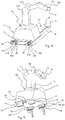
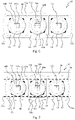
- FIGS. 6, 7 show a caster pack of the transport truck of FIGS. 1 to 5 .
- FIG. 1 One embodiment of a packaging plant 2 according to the invention is schematically illustrated in FIG. 1 .
- the packaging plant 2 comprises a packaging machine 4 as well as a robot 6 which is mounted on a transport truck 8 .
- the transport truck 8 is repositionable along the packaging machine 4 .
- the packaging machine 4 comprises a plurality of processing stations, such as, for example, a heating device 10 , a forming station 12 , a filling station 14 , a sealing station 16 , a punching station 18 , as well as arbitrary further processing stations (not illustrated), which may include a transfer device, a transport device, a supply device for accompanying material in the pack, such as brochures or leaflets, and a cartoner, the aforementioned being downstream of the punching station 18 .
- processing stations such as, for example, a heating device 10 , a forming station 12 , a filling station 14 , a sealing station 16 , a punching station 18 , as well as arbitrary further processing stations (
- the plurality of processing stations 10 , 12 , 14 , 16 , 18 are arranged successively in a processing direction D of the packaging machine 4 , said processing direction D being directed from an entry region 20 of the packaging machine 4 to an exit region 21 of the packaging machine 4 .
- the packaging machine 4 is preferably configured as a blister pack machine having an entry region 20 in which a forming film 22 on a roll 22 a and a cover film 24 on a roll 24 a can be provided.
- the forming film 22 runs through the heating device 10 for heating the forming film 22 , the forming station 12 for forming product receptacles, such as blister cups, in the forming film 22 , the filling station 14 for filling products into the product receptacles of the forming film 22 , the sealing station 16 for sealing the cover film 24 on the forming film 22 , and the punching station 18 for punching individual blister packs from the composite of the forming film 22 and the cover film 24 .
- the robot 6 is configured to interact with the packaging machine 4 .
- the robot 6 is in particular configured to interact with the plurality of processing stations 10 , 12 , 14 , 16 , 18 and is therefore preferably repositionable along all processing stations of the plurality of processing stations 10 , 12 , 14 , 16 , 18 .
- the packaging plant 2 can further comprise at least one assembly area 26 , or, as illustrated, a plurality of assembly areas 26 , for consumable material, and the robot 6 in this instance is configured to supply the plurality of processing stations 10 , 12 14 , 16 , 18 with consumable material.
- further rolls 22 a , 24 a of the forming film 22 , or of the cover film 24 , respectively, can be provided in the assembly area 26 close to the entry region 20 , and the robot 6 is configured to fill the packaging machine 4 in the entry region 20 with a new roll 22 a , 24 a , when required.
- the robot 6 in particular when changing the format, can also be configured to place a lead of the forming film 22 into the packaging machine 4 . To this end, the robot guides a free end portion of the forming film 22 through the plurality of processing stations 10 , 12 , 14 , 16 , 18 and about deflection elements 28 in the packaging machine 4 .
- the robot 6 can also be configured to place a lead of the cover film 24 into the packaging machine 4 in that said robot 6 guides a free end portion of the cover film 24 about deflection elements 28 in the packaging machine 4 and at least into the sealing station 16 . Further, the robot 6 can be configured to replace at least one product hopper of the filling station 14 with a filled product hopper, or for filling the at least one product hopper with products, when required.
- the robot 6 in particular when changing the format, can further be configured to replace tools of the plurality of processing stations 10 , 12 , 14 , 16 , 18 , such as, for example, a forming tool of the forming station 12 , a sealing tool of the sealing station 16 , or a punching tool of the punching station 18 .
- the robot 6 can also be configured to clean at least one processing station of the plurality of processing stations 10 , 12 , 14 , 16 , 18 , such as the filling station 14 , for example. Suitable to this end is, for example, cleaning by compressed air or CO 2 .
- At least one first processing station of the plurality of processing stations 10 , 12 , 14 , 16 , 18 can be arranged in a clean room R so that the robot 6 in the region of the first processing station is also arranged in the clean room.
- the first processing station corresponds to the filling station 14 .
- the clean room R is configured between borders indicated by dashed lines and therein usually delimited from the other processing stations 10 , 12 , 16 , 18 of the plurality of processing stations 10 , 12 , 14 , 16 , 18 by suitable partitions.
- a further robot 6 ′ which is mounted on a further transport truck 8 is indicated in FIG. 1 , wherein the further transport truck 8 ′ is also repositionable along the packaging machine 4 .
- said robots 6 , 6 ′ can either be equipped with different tools for undertaking different tasks and/or be assigned to different processing stations of the plurality of processing stations 10 , 12 , 14 , 16 , 18 .
- the packaging plant 2 comprises at least one guide rail 30 , preferably two parallel guide rails 30 , 32 , which run along the packaging machine 4 , wherein the transport truck 8 is mounted so as to be movable on the guide rails 30 , 32 .
- the guide rails 30 , 32 preferably run parallel to the processing direction D of the packaging machine 4 .
- a turnout or switch 34 on which the transport truck 8 can be guided onto the guide rails 30 , 32 or away from the guide rails, respectively, can further be provided.
- the transport truck 8 is described in more detail hereunder with reference to FIGS. 2-5 .
- the transport truck 8 comprises a plurality of operating components, which comprise, for example, a data transmission device 36 for wirelessly communicating with a machine controller of the packaging machine 4 , a drive 38 for moving the transport truck 8 along the packaging machine 4 , and at least one compressor 40 , 41 .
- the transport truck 8 moreover comprises a current collector 42 for transmitting an electric current to the transport truck 8 .
- the data transmission device 36 can be an optical data transmission installation.
- the transport truck 8 here comprises two compressors, one of which is configured as a compressed air compressor 40 and the other as a vacuum pump 41 .
- the current collector 42 is configured to wirelessly connect to a current source.
- the compressor 40 can be a compressed air compressor for supplying the robot with compressed air and/or a vacuum pump for supplying the robot with negative pressure.
- the transport truck 8 further comprises a frame 44 which supports the plurality of operating components, thus the data transmission device 36 , the drive 38 , and the compressor 40 , as well as the current collector 42 .
- the frame 44 of the transport truck 8 preferably also supports all further operating components and installations of the transport truck 8 that are described herein.
- the plurality of operating components of the transport truck 8 also comprises a first control device 46 for controlling the drive 38 and a second control device 48 for controlling the robot 6 .
- the plurality of operating components can comprise a first mains adapter 50 and a second mains adapter 52 , each being electrically connected to the current collector 42 .
- the first and the second mains adapter 50 , 52 are provided for supplying electric power to the operating components on the transport truck 8 and to the robot 6 , and convert an input voltage that is received from the current collector 42 to various output voltages.
- the first mains adapter 50 for supplying the plurality of operating components converts the input voltage to a first output voltage of, for example, 24 V.
- the second mains adapter 52 for supplying the robot 6 can convert the input voltage to a second output voltage of, for example, 600 V.
- the frame 44 moreover comprises a bearing assembly 54 which supports the robot 6 .
- the robot 6 here comprises a first through to a fourth arm 55 a - d of which in each case two adjacent arms are connected to one another in an articulated manner about at least one axis 6 a - f. Illustrated in FIG. 5 are a first axis 6 a, a second axis 6 b, a third axis 6 c, a fourth axis 6 d, a fifth axis 6 e and a sixth axis 6 f about which the arms 55 a - d of the robot 6 are able to be moved.
- the robot 6 for moving the at least one adjacent arm 55 a - d of the robot 6 about the respective axis 6 a - 6 f, can have one servomotor for each axis 6 a - 6 f.
- Each of these servomotors is electrically connected to the second mains adapter 52 and is connected so as to communicate with the second control device 48 .
- the frame 44 of the transport truck 8 is mounted so as to be movable along the packaging machine 4 .
- the transport truck 8 comprises a plurality of casters 56 , by which the frame 44 of the transport truck 8 is mounted so as to be movable on the guide rails 30 , 32 .
- the frame 44 can have one or a plurality of supports 58 on which the plurality of casters 56 are rotatably mounted.
- the frame 44 has four supports 58 , to each of which three casters 56 are attached.
- the transport truck 8 comprises a plurality of caster packs 60 , each of which comprises at least two casters 56 of the plurality of casters 56 and one support 58 .
- One preferred embodiment of the caster packs 60 as well as the mounting of the latter on the transport truck 8 is described with reference to FIGS. 6 and 7 .
- the guide rails 30 , 32 preferably have a substantially C-shaped cross-sectional profile having in each case one first leg 30 a , 32 a and one second leg 30 b , 32 b and one third leg 30 c , 32 c .
- the second and the third leg 30 b ,c, 32 b ,c extend perpendicularly from in each case one end of the first leg 30 a , 32 a .
- the respective first leg 30 a , 32 a is vertically aligned
- each second and third leg 30 b,c , 32 b,c is horizontally aligned.
- the guide rails 30 , 32 between the second and the third leg 30 b,c , 32 b,c form in each case a receptacle for the casters 56 .
- the lower two legs 30 b , 32 b of the guide rails 30 , 32 support the load of the transport truck 8 having the robot 6 .
- the upper third legs 30 c , 32 c can absorb forces which result from a tilting moment during abrupt movements of the transport truck 8 or the robot 6 .
- the casters 56 can particularly preferably also be axially supported on the respective first leg 30 a , 32 a of the guide rails 30 , 32 , as is derived from the description of FIGS. 6 and 7 .
- the packaging plant 2 For moving the transport truck 8 along the packaging machine 4 , the packaging plant 2 comprises a rack 62 , and the drive 38 of the transport truck 8 comprises a pinion 64 which engages with the rack 62 .
- a rotational driving movement of the drive 38 is converted to a translatory movement of the transport truck 8 along the rack 62 by way of the rack 62 and the pinion 64 .
- the rack 62 runs along the packaging machine 4 , preferably parallel to the guide rails 30 , 32 .
- the rack 62 can also be arranged on a guide rail 30 , in particular on the upper third leg 30 c.
- the rack 62 and the pinion 64 are arranged so as to be horizontally next to one another.
- the rotation axis of the pinion 64 thus extends vertically.
- the teeth of the rack 62 and of the pinion 64 are directed towards the side.
- the tips or end faces of the teeth of the rack 62 in this instance run substantially vertically and not horizontally. It is prevented as a result that contamination can accumulate in the troughs between the teeth, good cleaning of the packaging plant 2 being facilitated as a result.
- the packaging plant 2 comprises a current conductor 66 which here is configured as a conductor rail and is in sliding contact with the current collector 42 .
- the current conductor 66 is connected to a voltage source of the packaging plait 2 and by way of the latter supplies the current collector 42 and thus the transport truck 8 with electric voltage.
- the current conductor 66 also runs parallel to the guide rails 30 , 32 , preferably so as to be spaced apart from the latter, in order to be readily accessible for the current collector 42 .
- the current conductor 66 can be arranged between the two guide rails 30 , 32 or preferably laterally outside the two guide rails 30 , 32 .
- the current collector 42 and the current conductor 66 preferably have a corresponding cross-sectional shape, such that the current collector 42 partially surrounds the current conductor 66 so as to ensure a reliable and uninterrupted current supply.
- a cover 68 in the region of the guide rails 30 , 32 which forms a casing in which the guide rails 30 , 32 and preferably also the current conductor 66 and the rack 62 are received, as a result of which said guide rails 30 , 32 , said current conductor 66 and said rack 62 in relation to the plurality of processing stations 10 , 12 , 14 , 16 , 18 are protected against contamination.
- the cover 68 is configured in multiple parts and comprises a first cover portion 70 , a second cover portion 72 and a third cover portion 74 .
- the cover portions 70 , 72 , 74 are arranged in such a manner that said cover portions 70 , 72 , 74 form a gap 76 , 78 above each guide rail 30 , 32 .
- a first gap 76 which is parallel to and above the guide rail 30 is configured between the first and the second cover portion 70 , 72
- a second gap 78 which is parallel to and above the guide rail 32 is configured between the second and the third cover portion 72 , 74 .
- the transport truck 8 is mounted on the guide rails 30 , 32 through the first and the second gap 76 , 78 , for example in that the supports 58 from the frame 44 extend through the first and/or the second gap 76 , 78 , respectively.
- the ingress of contamination through the first and the second gap 76 , 78 can further be minimized in that brushes (not illustrated) are arranged on each gap 76 , 78 , the bristles of said brushes extending transversely through the respective gap 76 , 78 and thus retaining contamination, while at the same time not impeding the movement of the transport truck 8 along the guide rails 30 , 32 .
- the data transmission device 36 can comprise a first communications interface 80 which is configured to communicate with the machine controller and below the frame 44 of the transport truck 8 is arranged on the latter.
- the first communications interface 80 is attached to a support 58 in order for said communications interface 80 to be placed below the cover 68 .
- the machine controller can be connected so as to communicate with a transmission installation 82 which is in particular configured as a transmitter.
- the first communications interface 80 is configured as a receiver so that the transmission installation 82 and the communications interface 80 can mutually communicate by way of a light beam 84 , as is indicated in FIG. 2 .
- the first communications interface 80 as well as the transmission installation 82 can in each case be configured as a transmitter and receiver in order to enable bidirectional communication.
- the light beam 84 extends so as to be approximately at the height level of the casters 56 .
- the light beam 84 is particularly preferably aligned so as to be parallel to the direction of movement and thus to the guide rails 30 , 32 because said light beam thus guarantees a connection between the transmission installation 82 and the first communications interface 80 , substantially irrespective of the position of the transport truck 8 relative to said transmission installation 82 .
- the light beam 84 does not have to follow the movement of the transport truck 8 because the latter only moves parallel to the light beam 84 .
- the data transmission device 36 may further comprise a second communications interface 86 (see FIG. 2 ) which is configured to communicate with a data transmission device 36 ′ of the further transport truck 8 ′.
- the second communications interface 86 is in particular configured as a transmitter but may also be configured as a transmitter and receiver so that the communication between the further transport truck 8 ′ and the transport truck 8 can take place in a bidirectional manner.
- the second communications interface 86 is preferably arranged and configured in a manner analogous to the first communications interface 80 , with the difference that the first communications interface 80 faces the transmission installation 82 and the second communications interface 86 faces the further transport truck 8 ′.
- the further transport truck 8 ′ can receive a control signal which is sent from the transmission installation 82 to the first communications interface 80 , is received by the latter and relayed to the second communications interface 86 , and by the second communications interface 86 is sent to the further transport truck 8 ′ by a light beam 88 .
- a caster pack 60 is illustrated in more detail in FIGS. 6 and 7 .
- the caster pack 60 comprises at least two, here three, casters 56 of the plurality of casters 56 and a support 58 on which the casters 56 are rotatably mounted.
- the support 58 for each caster 56 has one receptacle 90 which receives and establishes a mounting 92 of the respective caster 56 .
- the support 58 can be configured so as to be integral with the frame 44 of the transport truck 8 , can be fixedly connected to the frame 44 , or can be mounted so as to be pivotable on the frame 44 of the transport truck 8 , as illustrated. This can be achieved, for example, in that the support 58 comprises two bearing locations 94 a,b that are preferably symmetrically arranged.
- the frame 44 has a recess 96 which receives the support 58 and has two bearing seats 98 a,b that correspond to the bearing locations 94 a,b of the support 58 .
- the support 58 can have a substantially rectangular shape, wherein the bearing locations 94 a,b are configured so as to be integral with the support 58 and in the form of a segment extend outwards from in each case a longitudinal periphery (or a broad side 58 a ) of the support 58 .
- the bearing seats 98 a,b as bearing shells are configured in the corresponding shape of a segment so that the bearing locations 94 a,b and the bearing seats 98 a,b are in mutual planar contact so as to permit the support 58 to pivot in the recess 96 .
- the recess 96 in the regions next to the bearing seats 98 a,b is larger than the support 58 , as can be seen in FIG.
- At least one caster 56 of the caster pack 60 is adjustable in a direction perpendicular to a running surface of the at least one guide rail 30 , 32 and preferably to a rotation axis 56 a of the caster 56 .
- the central caster 56 is adjustable.
- the rotation axis 56 a is aligned so as to be perpendicular to the drawing plane.
- the direction of adjustment is identified by the arrow V.
- the receptacle 90 of the adjustable caster 56 in the direction V is larger than the mounting 92 of the caster 56 , while the width of the receptacle 90 in a direction transverse to the direction V corresponds substantially to the width of the mounting 92 .
- the mounting 92 is received in the receptacle 90 so as to be displaceable in the direction V, and the caster 56 is correspondingly mounted so as to be displaceable in the direction V.
- the adjustment of the caster 56 can be performed by a threaded pin 100 , for example, which is aligned so as to be parallel to the direction V.
- the second and the third leg 30 b,c of the C-shaped guide rail 30 are indicated by dashed lines in FIG. 7 .
- the two outer casters 56 bear on the second leg 30 b and support the weight of the transport truck 8 and of the robot 6 on the guide rail 30 .
- the central, adjustable caster 56 can now be precisely positioned in relation to the upper third leg 30 c so that upwardly directed forces can also be transmitted to the guide rail 30 by way of said caster 56 .
- the transport truck 8 can also be laterally supported on the at least one guide rail 30 .
- support casters 102 can be provided, the axis 102 a of the latter being aligned so as to be perpendicular to the running surface of the guide rail 30 .
- the support casters 102 can roll on the vertical first leg 30 a , 32 a of the respective guide rail 30 , 32 and transmit a force to said leg 30 a , 32 a .
- the axis 102 a of the support casters 102 is preferably aligned so as to be perpendicular to the axis 56 a of the casters 56 , and a transmission of force from the support casters 102 to the guide rails 30 , 32 takes place in the axial direction of the casters 56 .
- one support caster 102 is in each case rotatably mounted in a hub 56 b of a caster 56 , or in the mounting 92 of a caster 56 .
Landscapes
- Engineering & Computer Science (AREA)
- Mechanical Engineering (AREA)
- Robotics (AREA)
- Human Computer Interaction (AREA)
- Computer Networks & Wireless Communication (AREA)
- Physics & Mathematics (AREA)
- Fluid Mechanics (AREA)
- Power Engineering (AREA)
- Transportation (AREA)
- Auxiliary Devices For And Details Of Packaging Control (AREA)
Abstract
Description
- This application claims the benefit of priority under 35 U.S.C. § 119 to European Patent Application No. 20 213 797.2, filed Dec. 14, 2020, the contents of which is incorporated herein by reference in its entirety.
- The present disclosure relates to a packaging plant comprising a packaging machine and a robot which on a transport truck is repositionable along the packaging machine.
- Packaging plants in which robots on trucks are repositionable between a store which provides consumable materials and individual processing stations of the packaging plant, said robots supplying the processing stations with consumable materials, are known from the prior art. The possibilities in terms of the application of such robots are however very limited.
- Conversely, if the robots are to support the operator of the plant in any other aspect, for example when changing over the format of the packaging plant, collaborating robots can be used. In order to guarantee a sufficient level of safety, said robots are however often limited in terms of the dimensions thereof and the forces that can be absorbed, and thus in turn in terms of the possible applications of said robots.
- It is therefore an object of the present invention to provide a packaging plant having a robot which is able to be used in an ideally simple and flexible manner.
- According to one aspect of the present disclosure, a packaging plant comprises a packaging machine having a plurality of processing stations that are arranged successively in a processing direction of the packaging machine, and a robot which is mounted on a transport truck, wherein the transport truck is repositionable along the packaging machine. The transport truck comprises a frame, a current collector, and a plurality of operating components. The frame is mounted so as to be movable along the packaging machine, has a bearing assembly on which the robot is mounted, and supports the plurality of operating components. The current collector for transmitting an electric current to the transport truck is configured to wirelessly connect to a current source. The plurality of operating components comprise a data transmission device which is configured to wirelessly communicate with a machine controller of the packaging machine, and a drive for moving the transport truck along the packaging machine. The plurality of operating components further preferably comprise at least one compressor, in particular a compressed air compressor and/or a vacuum pump.
- Provided in this way is a packaging plant having a robot which on the transport truck carries along all operating components required for operating a plurality of different tools, such as holding and gripping installations, and as a result is able to be used in a flexible manner for a plurality of different tasks. Moreover, the transport truck and the robot are able to be operated and repositioned without a drag chain, as a result of which the flexibility is further enhanced, the maintenance input is reduced, and high requirements in terms of hygiene can be met.
- In order for the plurality of operating components and the current collector to be supported, said operating components and said current collector are attached to the frame of the transport truck. Alternatively, the current collector and the plurality of operating components can also in each case be individually attached to a housing of the transport truck, said housing in turn being fastened to the frame or in a self-supporting manner forming a frame. This applies also to all further operating components and elements of the transport truck that are described hereunder and are supported or received, respectively, by the frame.
- The transport truck is preferably able to be operated in a wireless manner, thus is not wire-bound. This means that no wires, in particular no current lines, signal lines or fluid lines, for connecting the transport truck to an external current source, control device, or fluid supply, respectively, are provided on the transport truck. Rather, the transport truck carries on board all components required to this end, or has wireless (current, data) connections. As a result, a drag chain which would otherwise be required for supplying the transport truck and the robot can be dispensed with, while the robot can at the same time handle a plurality of tasks.
- The absence of a drag chain further leads to the transport truck and the robot being easier to clean, or such a drag chain, which is complex in terms of cleaning, not having to be cleaned, respectively. In one preferred embodiment, at least one first processing station of the plurality of processing stations of the packaging machine is arranged in a clean room and the transport truck with the robot, at least in the region of the first processing station, is likewise arranged in the clean room. The first processing station is preferably a filling station in which products are filled into an item of packaging. The application range of the robot can thus also be extended as a result.
- The at least one compressor can be a compressed air compressor and/or a vacuum pump. The transport truck preferably comprises two compressors, one of which is configured as a compressed air compressor and the other as a vacuum pump. A plurality of compressed air compressors and/or a plurality of vacuum pumps can also be provided. The compressor by a fluid line is preferably connected to a tool of the robot, said tool being able to be activated by the fluid. For example, the tool can be a holding/gripping device or a clamping device which can be activated, in particular opened and closed, by compressed air from the compressed air compressor. The tool can also be a suction device, for example, which by negative pressure from the vacuum pump suctions items, in particular products to be packaged or portions of films, and as a result acquires said items for further handling.
- The plurality of operating components of the transport truck can also comprise a hydraulic apparatus which is supported by the frame. The hydraulic apparatus by a hydraulic line is preferably connected to a tool of the robot, said tool being able to be activated by the hydraulic fluid, as described above in the context of the compressor.
- The robot is preferably a multi-axis robot, preferably a robot with 2, 3, 4, 5 or 6 axes. The multi-axis robot can have a plurality of servomotors, wherein the number of the plurality of servomotors corresponds to the number of axes of the multi-axis robot. The robot thus comprises one servomotor on each axis.
- It is preferable for the plurality of operating components to further comprise a control device for controlling the drive and for controlling the robot. A control device for controlling the drive hereunder is also referred to as the first control device, and a control device for controlling the robot hereunder is also referred to as the second control device. The first and the second control device can be configured so as to be mutually integral, i.e. formed by a common control device which assumes both functions. The first and the second control device can however also be configured so as to be mutually separate. The first control device is connected so as to communicate with the drive of the truck. The second control device is connected so as to communicate with the robot and in particular with each of the plurality of servomotors of the robot. The second control device for controlling a tool of the robot can also be connected so as to communicate with this tool, in particular with at least one control valve of the tool.
- Further, the first and the second control device can be connected so as to communicate with the data transmission installation. By the data transmission installation, said first and said second control device can in turn be connected so as to communicate with the machine controller of the packaging machine. The frame of the transport truck also supports the first and the second control device.
- The plurality of operating components can further comprise a control device for controlling the at least one compressor. The control device for controlling the at least one compressor hereunder is also referred to as the third control device and, in a manner analogous to the first and second control device, can be configured so as to be integral with the first and the second control device or so as to be separate therefrom.
- The control device can generally also assume functions for guaranteeing the safety of personnel and for guaranteeing the safe operation of the transport truck and of the robot. To this end, the control device is connected so as to communicate with corresponding sensors, as described below.
- The transport truck preferably comprises at least one first mains adapter and one second mains adapter which are in each case electrically connected to the current collector, wherein the first mains adapter for the electrical power supply of the plurality of operating components on the transport truck is configured to convert an input voltage to a first output voltage, and wherein the second mains adapter for the electrical power supply of the robot, in particular of each of the plurality of servomotors of the robot, on the transport truck is configured to convert the input voltage to a second output voltage. As a result, the voltages required in each case for the electrical power supply of the operating components and of the robot can be provided directly on the transport truck.
- In particular, the first mains adapter can be electrically connected selectively to one or a plurality from the drive, the compressor, the first and the second control device, and the data transmission installation. The second mains adapter is preferably electrically connected to each of the plurality of servomotors of the robot. The input voltage is preferably an AC voltage between 200 V and 600 V, more preferably between 300 V and 500 V, most preferably between 350 V and 450 V. The first output voltage is preferably a DC voltage between 6 V and 32 V, more preferably between 12 V and 24 V. The second output voltage is preferably a DC voltage between 500 V and 700 V, more preferably between 550 V and 650 V. The frame of the transport truck also supports the first and the second mains adapter.
- The plurality of components can further comprise at least one sensor. The at least one sensor is selected from an optical sensor, such as, for example, a camera system, for identifying goods to be transported, for documenting the operation of the robot or for monitoring an environment of the robot, one or a plurality of position sensors for identifying the position of the transport truck and/or of the robot, and an acceleration or vibration sensor for monitoring the transport truck and/or the robot. One position sensor can in each case be provided on the drive as well as on the servomotors of the robot. In order to identify operating positions, tools and workpieces, the sensor may also be a code-scanning sensor. Laser or radar sensors are also suitable for monitoring the environment of the robot. An additional sensor can also be a mechanical, capacitive or inductive sensor on a robotic tool for fulfilling the process tasks. The plurality of sensors can comprise an arbitrary number and combinations of the sensors described here.
- The packaging plant in one preferred embodiment comprises at least one guide rail which runs along the packaging machine and preferably, at least in portions, parallel to the processing direction, wherein the frame of the transport truck is mounted so as to be movable on the at least one guide rail. The at least one guide rail preferably runs below the transport truck so that the latter, together with the robot, stands on the guide rail. The packaging plant preferably comprises two parallel guide rails, as described above, so as to enable ideally stable mounting and guiding of the transport truck.
- The at least one guide rail preferably has a substantially C-shaped cross-sectional profile having a first leg, a second leg and a third leg, wherein the second and the third leg extend in a substantially perpendicular manner from in each case one end of the first leg. The first leg is preferably aligned so as to be substantially vertical, and the second and the third leg are aligned so as to be substantially horizontal. The transport truck in this instance is mounted between the second and the third leg of the guide rail, and as a result is supported in an upward as well as downward manner. The weight of the transport truck and of the robot arranged thereon here acts downward on the second leg. In the event of abrupt movements of the transport truck or of the robot, tilting moments may however arise, forces directed in an upward manner resulting from said tilting moments. These forces then act in an upward manner on the third leg of the guide rail. The transport truck can further also be supported laterally in relation to the first leg of the at least one guide rail. If two guide rails are provided, these are preferably arranged in such a manner that the openings thereof of the C-shaped cross-sectional profile face away from one another, i.e. that the second and the third legs of the two guide rails are aligned in opposite directions.
- The at least one guide rail can have a turnout or a switch where the transport truck can be introduced and removed. As an alternative, for this purpose an access can preferably be provided at one end of the at least one guide rail. As a result, variously equipped transport trucks or robots can be introduced into the packaging plant in a simple manner, or transport trucks having contaminated robots can be removed for cleaning, for example.
- In order for the transport truck to be movably mounted on the at least one guide rail, the transport truck preferably comprises a plurality of casters and the frame of the transport truck by the plurality of casters is mounted so as to be movable on the at least one guide rail. The plurality of casters completely supports the transport truck on the at least one guide ran, said plurality of casters thus absorbing the entire load of the transport truck and of the robot.
- Each caster of the plurality of casters is preferably arranged between the second and the third leg of the at least one C-shaped guide rail. An upper side of the second leg in this instance forms a running surface for the casters. Moreover, each caster can be axially supported on the first leg of the at least one C-shaped guide rail. If two guide rails are provided, the transport truck preferably comprises a plurality of casters for each guide rail, in order to be mounted in an ideally stable manner.
- Alternatively, the transport truck could also be mounted by a linear friction bearing, a floating bearing on a magnetic rail, or simply by wheels on the floor.
- In one particularly preferred embodiment, the transport truck comprises a plurality of caster packs, wherein each caster pack comprises at least two casters, preferably three casters, of the plurality of casters and one support on which the at least two casters are rotatably mounted. The support can be configured so as to be integral with the frame of the transport truck, can be attached to the frame of the transport truck, or particularly preferably can be mounted so as to be pivotable on the frame of the transport truck. The transport truck preferably comprises two caster packs for each guide rail, wherein the two caster packs are mutually spaced apart in the longitudinal direction of the guide rail.
- In order to achieve an ideally precise mounting of the transport truck on the at least one guide rail, one caster of the at least two casters of each caster pack can be adjustable in a direction perpendicular to the running surface of the at least one guide rail and preferably perpendicular to a rotation axis of the caster. To this end, the axis of the adjustable caster is preferably mounted so as to be correspondingly displaceable in the respective support. The running surface of the at least one guide rail is a face of the second leg of the at least one C-shaped guide rail that faces the casters. Each caster pack preferably comprises three casters, of which the central caster is adjustable perpendicular to the running surface. As a result of this configuration of the caster packs, it is achieved that the transport truck, together with the robot, in the direction of the weight is reliably supported on the at least one guide rail, on the one hand, while the adjustable caster can be precisely positioned in relation to the upper third leg of the at least one C-shaped guide rail so as also to safely support tilting moments or unexpected movements. As a result, the transport truck and the robot are mounted in an optimal manner and so as to run silently in any situation.
- In order for the voltage to be wirelessly transmitted to the current collector, the packaging plant preferably comprises a current conductor, in particular a conductor cable or a conductor rail, wherein the current collector of the transport truck is in sliding contact with the current conductor. A wireless current supply which can be implemented in an effective and cost-effective manner is enabled as a result.
- The current conductor is connected to a voltage source and by way of the latter supplies the current collector nd thus the transport truck with electric voltage. The current conductor is preferably arranged parallel to and at the height level of the at least one guide rail. For example, the current conductor runs at a spacing of 20 mm to 140 mm, more preferably of 40 mm to 80 mm, from the at least one guide rail. If two guide rails are provided, the current conductor can be arranged between the two guide rails or preferably laterally outside the two guide rails.
- The current collector of the transport truck preferably partially surrounds the current conductor, so as to ensure a reliable and uninterrupted current supply. For example, the current collector is configured as a conductor rail which has a substantially rectangular cross section, and the current collector surrounds and contacts the conductor rail on at least two or three sides. The current conductor can also be configured so as to be integral with the guide rail.
- Alternatively, the voltage could also be transmitted to the current collector by induction.
- In order to move the transport truck along the packaging machine, the packaging plant can further comprise a rack which runs along the packaging machine, and the drive of the transport truck can comprise a pinion which engages with the rack. The drive of the transport truck preferably comprises an electric motor, the pinion being mounted on the driveshaft of said electric motor. The combination of rack and pinion is particularly well-suited for driving the transport truck because high forces can be transmitted and high rates of acceleration can be achieved. Moreover, a division of the rack can be chosen in such a manner that the rack as well as the at least one guide rail can be configured in a modular manner and a length of each rack module corresponds to a length of each guide rail module.
- The rack is preferably arranged parallel to and at the height level of the at least one guide rail. For example, the rack in this instance runs at a spacing of 30 mm to 140 mm, more preferably of 50 mm to 80 mm, from the at least one guide rail. If two guide rails are provided, the rack can be arranged between the two guide rails or laterally outside the two guide rails. However, the rack can also be arranged on the at least one guide rail, for example on an upper side of the third leg of the C-shaped guide rail.
- it is further preferable for the rack to be arranged in such a manner that teeth of the rack are directed towards the side. The tips or end faces of the teeth of the rack in this instance run substantially vertically and not horizontally. It is prevented as a result that contamination can accumulate in the troughs between the teeth, good cleaning of the packaging plant being further facilitated as a result.
- Alternatively, driving the transport truck can also take place by way of driven wheels, an (electromagnetic) linear drive, a pulley, or a (timing) belt drive.
- In order to be able to even better clean the packaging plant, the packaging plant preferably comprises a cover in the region of the at least one guide rail. The cover is preferably configured in multiple parts and forms a casing in which the at least one guide rail and preferably also the current conductor and the rack are received, as a result of which said guide rail, said current conductor and said rack in relation to the plurality of processing stations of the packaging machine are protected against contamination. The cover, or the casing formed by the latter, respectively, has a gap above and along the at least one guide rail, the transport truck being mounted on the at least one guide rail through said gap. In the case of two guide rails, the cover, or the casing, respectively, correspondingly has two gaps. Brushes which further reduce contamination of underlying regions but do not compromise the mobility of the transport truck can be provided in each gap. It is also conceivable that the transport truck further comprises a cleaning device, in particular in the form of a suction device, so as to clean the gap and/or the underlying regions. In order to avoid the contamination of the gap, the cover can also be configured in such a manner that the latter dynamically opens ahead of the passing transport truck and doses behind the latter.
- In one further embodiment, the packaging plant comprises at least one further robot which is mounted on a further transport truck, wherein the further transport truck is repositionable along the packaging machine. The further robot and the further transport truck can be configured according to the preceding description and consequently have all features of the robot, or the transport truck, respectively, described herein. In order to facilitate the description of the robot and of the further robot, said robot and said further robot hereunder are also referred to as the first and the second robot. In order to facilitate the description of the transport truck and of the further transport truck, said transport truck and said further transport truck hereunder are also referred to as the first and the second transport truck. It is understood that an arbitrary plurality of robots or transport trucks, respectively, can also be provided in an analogous manner.
- The first and the second transport truck are preferably arranged on the same at least one guide rail. The first and the second robot can handle different tasks, for example have different tools. In order for the efficiency to be increased, the first and the second robot can in each case also be assigned to part of the plurality of processing stations of the packaging machine so as to keep the travel distances short.
- A reliable, secure and rapid data transmission is guaranteed in that the data transmission device is preferably an optical data transmission installation. The optical data transmission can take place by optical transmission in free space, for example by laser or infrared. The data transmission by the data transmission device preferably takes place at a data transmission rate of at least 16 Mbits/s, more preferably at least 50 Mbits/s, most preferably at least 100 Mbits/s.
- The packaging plant preferably comprises an optical transmission installation which can be configured as a freely emitting transmitter. The data transmission device is preferably connected so as to communicate with the machine controller of the packaging machine. The data transmission device on the transport truck comprises a corresponding receiver. A light beam for the transmission of data is aligned between the transmission installation and the data transmission installation.
- It is understood that the transmission of data can also take place in a bidirectional manner and the transmission installation as well as the data transmission device are configured as a transmitter as well as a receiver. In order for the transmitter and receiver as well as the light beam to be protected, at least the data transmission device and preferably also the transmission installation can be arranged in the region of the at least one guide rail, in particular below the cover, or within the casing formed by this cover, respectively.
- In one preferred embodiment, the data transmission device comprises a first communications interface and a second communications interface, wherein the first communications interface is configured to communicate with the machine controller, and the second communications interface is configured to communicate with a data transmission device of the second transport truck.
- Consequently, the first communications interface corresponds to the previously described receiver of the data transmission device of the transport truck. The first communications interface is therefore attached to the first transport truck so as to face the transmission installation of the packaging plant. The second communications interface is attached to the first transport truck so as to face the second transport truck. A signal intended for the second transport truck can be transmitted from the transmission installation to the first communications interface of the first transport truck, and from the first transport truck by the second communications interface be sent to the data transmission device of the second transport truck.
- Finally, the plurality of processing stations comprise at least one forming station, one filling station, one sealing station, one punching station, and one cartoner, wherein the robot is repositionable along all processing stations of the plurality of processing stations. The packaging plant further comprises at least one assembly area for consumable material, wherein the robot is configured to supply the plurality of processing stations with consumable material. The packaging machine in this case is preferably configured as a blister pack machine.
- The packaging machine as a processing station in the processing direction can further comprise an entry region for example for providing a forming film and/or a cover film ahead of the forming station, a heating device ahead of the forming station, a transfer device to a transport device between the punching station and the cartoner, and a supply device for accompanying material in the pack, such as brochures or leaflets. The robot can be configured to interact with at least part of these stations or devices, respectively, or with each of these stations or devices, respectively.
- For example, the robot can be configured to fill the packaging machine in the entry region with a new roll of a forming film and/or of a cover film, when required. The robot, in particular when changing the format, can be configured to place a lead of the forming film and/or of the cover film into the packaging machine. To this end, the robot guides a free end portion of the forming film or cover film, respectively, through the plurality of processing stations and about deflection elements in the packaging machine. Further, the robot can be configured to replace at least one product hopper of the filling station with a filled product hopper, or for filling the at least one product hopper with products, when required. The robot, in particular when changing the format, can further be configured to replace tools of the plurality of processing stations, such as, for example, a forming tool of the forming station, a sealing tool of the sealing station, or a punching tool of the punching station. Finally, the robot can also be configured to clean at least one processing station of the plurality of processing stations, such as the filling station, for example. Suitable to this end is, for example, cleaning by compressed air or CO2, by a suction device or a wiping device.
-
FIG. 1 schematically shows a packaging plant according to one embodiment of the invention in a perspective view. -
FIG. 2 schematically shows a transport truck of the packaging plant ofFIG. 1 in a perspective view, with the components received by said transport truck. -
FIG. 3 schematically shows a fragment of the packaging plant ofFIG. 1 in a perspective sectional view. -
FIG. 4 schematically shows the fragment ofFIG. 3 in a perspective view. -
FIG. 5 schematically shows a transport truck having a robot ofFIGS. 1 to 4 in a perspective view. -
FIGS. 6, 7 show a caster pack of the transport truck ofFIGS. 1 to 5 . - One embodiment of a
packaging plant 2 according to the invention is schematically illustrated inFIG. 1 . Thepackaging plant 2 comprises apackaging machine 4 as well as arobot 6 which is mounted on atransport truck 8. Thetransport truck 8 is repositionable along thepackaging machine 4. Thepackaging machine 4 comprises a plurality of processing stations, such as, for example, aheating device 10, a formingstation 12, a fillingstation 14, a sealingstation 16, a punchingstation 18, as well as arbitrary further processing stations (not illustrated), which may include a transfer device, a transport device, a supply device for accompanying material in the pack, such as brochures or leaflets, and a cartoner, the aforementioned being downstream of the punchingstation 18. The plurality ofprocessing stations packaging machine 4, said processing direction D being directed from anentry region 20 of thepackaging machine 4 to anexit region 21 of thepackaging machine 4. - The
packaging machine 4 is preferably configured as a blister pack machine having anentry region 20 in which a formingfilm 22 on aroll 22 a and acover film 24 on aroll 24 a can be provided. In this case, the formingfilm 22 runs through theheating device 10 for heating the formingfilm 22, the formingstation 12 for forming product receptacles, such as blister cups, in the formingfilm 22, the fillingstation 14 for filling products into the product receptacles of the formingfilm 22, the sealingstation 16 for sealing thecover film 24 on the formingfilm 22, and the punchingstation 18 for punching individual blister packs from the composite of the formingfilm 22 and thecover film 24. - The
robot 6 is configured to interact with thepackaging machine 4. Therobot 6 is in particular configured to interact with the plurality ofprocessing stations processing stations packaging plant 2 can further comprise at least oneassembly area 26, or, as illustrated, a plurality ofassembly areas 26, for consumable material, and therobot 6 in this instance is configured to supply the plurality ofprocessing stations - For example, further rolls 22 a, 24 a of the forming
film 22, or of thecover film 24, respectively, can be provided in theassembly area 26 close to theentry region 20, and therobot 6 is configured to fill thepackaging machine 4 in theentry region 20 with anew roll robot 6, in particular when changing the format, can also be configured to place a lead of the formingfilm 22 into thepackaging machine 4. To this end, the robot guides a free end portion of the formingfilm 22 through the plurality ofprocessing stations deflection elements 28 in thepackaging machine 4. In an analogous manner, therobot 6 can also be configured to place a lead of thecover film 24 into thepackaging machine 4 in that saidrobot 6 guides a free end portion of thecover film 24 aboutdeflection elements 28 in thepackaging machine 4 and at least into the sealingstation 16. Further, therobot 6 can be configured to replace at least one product hopper of the fillingstation 14 with a filled product hopper, or for filling the at least one product hopper with products, when required. Therobot 6, in particular when changing the format, can further be configured to replace tools of the plurality ofprocessing stations station 12, a sealing tool of the sealingstation 16, or a punching tool of the punchingstation 18. Finally, therobot 6 can also be configured to clean at least one processing station of the plurality ofprocessing stations station 14, for example. Suitable to this end is, for example, cleaning by compressed air or CO2. - At least one first processing station of the plurality of
processing stations robot 6 in the region of the first processing station is also arranged in the clean room. In the embodiment illustrated, the first processing station corresponds to the fillingstation 14. The clean room R is configured between borders indicated by dashed lines and therein usually delimited from theother processing stations processing stations - A
further robot 6′ which is mounted on afurther transport truck 8 is indicated inFIG. 1 , wherein thefurther transport truck 8′ is also repositionable along thepackaging machine 4. As a result of thepackaging plant 2 thus comprising a plurality ofrobots robots processing stations - The
packaging plant 2 comprises at least oneguide rail 30, preferably twoparallel guide rails packaging machine 4, wherein thetransport truck 8 is mounted so as to be movable on the guide rails 30, 32. The guide rails 30, 32 preferably run parallel to the processing direction D of thepackaging machine 4. In order for thetransport truck 8 to be introduced or removed, a turnout or switch 34 on which thetransport truck 8 can be guided onto the guide rails 30, 32 or away from the guide rails, respectively, can further be provided. - The
transport truck 8 is described in more detail hereunder with reference toFIGS. 2-5 . - As can be seen in
FIG. 2 , thetransport truck 8 comprises a plurality of operating components, which comprise, for example, adata transmission device 36 for wirelessly communicating with a machine controller of thepackaging machine 4, adrive 38 for moving thetransport truck 8 along thepackaging machine 4, and at least onecompressor transport truck 8 moreover comprises acurrent collector 42 for transmitting an electric current to thetransport truck 8. - The
data transmission device 36 can be an optical data transmission installation. Thetransport truck 8 here comprises two compressors, one of which is configured as acompressed air compressor 40 and the other as avacuum pump 41. Thecurrent collector 42 is configured to wirelessly connect to a current source. Thecompressor 40 can be a compressed air compressor for supplying the robot with compressed air and/or a vacuum pump for supplying the robot with negative pressure. - The
transport truck 8 further comprises aframe 44 which supports the plurality of operating components, thus thedata transmission device 36, thedrive 38, and thecompressor 40, as well as thecurrent collector 42. Theframe 44 of thetransport truck 8 preferably also supports all further operating components and installations of thetransport truck 8 that are described herein. For example, the plurality of operating components of thetransport truck 8 also comprises afirst control device 46 for controlling thedrive 38 and asecond control device 48 for controlling therobot 6. - Further, the plurality of operating components can comprise a
first mains adapter 50 and asecond mains adapter 52, each being electrically connected to thecurrent collector 42. The first and thesecond mains adapter transport truck 8 and to therobot 6, and convert an input voltage that is received from thecurrent collector 42 to various output voltages. In particular, thefirst mains adapter 50 for supplying the plurality of operating components converts the input voltage to a first output voltage of, for example, 24 V. Thesecond mains adapter 52 for supplying therobot 6 can convert the input voltage to a second output voltage of, for example, 600 V. - As can be seen in
FIGS. 3-5 , theframe 44 moreover comprises a bearingassembly 54 which supports therobot 6. Therobot 6 here comprises a first through to a fourth arm 55 a-d of which in each case two adjacent arms are connected to one another in an articulated manner about at least oneaxis 6 a-f. Illustrated inFIG. 5 are afirst axis 6 a, asecond axis 6 b, athird axis 6 c, afourth axis 6 d, afifth axis 6 e and asixth axis 6 f about which the arms 55 a-d of therobot 6 are able to be moved. Therobot 6, for moving the at least one adjacent arm 55 a-d of therobot 6 about therespective axis 6 a-6 f, can have one servomotor for eachaxis 6 a-6 f. Each of these servomotors is electrically connected to thesecond mains adapter 52 and is connected so as to communicate with thesecond control device 48. - The
frame 44 of thetransport truck 8 is mounted so as to be movable along thepackaging machine 4. To this end, thetransport truck 8 comprises a plurality ofcasters 56, by which theframe 44 of thetransport truck 8 is mounted so as to be movable on the guide rails 30, 32. Theframe 44 can have one or a plurality ofsupports 58 on which the plurality ofcasters 56 are rotatably mounted. In the embodiment illustrated, theframe 44 has foursupports 58, to each of which threecasters 56 are attached. As a result, thetransport truck 8 comprises a plurality of caster packs 60, each of which comprises at least twocasters 56 of the plurality ofcasters 56 and onesupport 58. One preferred embodiment of the caster packs 60 as well as the mounting of the latter on thetransport truck 8 is described with reference toFIGS. 6 and 7 . - As can be seen in
FIGS. 3 and 4 , the guide rails 30, 32 preferably have a substantially C-shaped cross-sectional profile having in each case onefirst leg second leg third leg third leg 30 b,c, 32 b,c extend perpendicularly from in each case one end of thefirst leg first leg third leg 30 b,c, 32 b,c is horizontally aligned. As a result, the guide rails 30, 32 between the second and thethird leg 30 b,c, 32 b,c form in each case a receptacle for thecasters 56. In the normal operation, the lower twolegs transport truck 8 having therobot 6. Moreover, the upperthird legs transport truck 8 or therobot 6. Thecasters 56 can particularly preferably also be axially supported on the respectivefirst leg FIGS. 6 and 7 . - For moving the
transport truck 8 along thepackaging machine 4, thepackaging plant 2 comprises arack 62, and thedrive 38 of thetransport truck 8 comprises apinion 64 which engages with therack 62. A rotational driving movement of thedrive 38 is converted to a translatory movement of thetransport truck 8 along therack 62 by way of therack 62 and thepinion 64. Therack 62 runs along thepackaging machine 4, preferably parallel to the guide rails 30, 32. As is illustrated, therack 62 can also be arranged on aguide rail 30, in particular on the upperthird leg 30 c. - In order to avoid the accumulation of contamination between the teeth of the
rack 62, therack 62 and thepinion 64 are arranged so as to be horizontally next to one another. The rotation axis of thepinion 64 thus extends vertically. As a result, the teeth of therack 62 and of thepinion 64 are directed towards the side. The tips or end faces of the teeth of therack 62 in this instance run substantially vertically and not horizontally. It is prevented as a result that contamination can accumulate in the troughs between the teeth, good cleaning of thepackaging plant 2 being facilitated as a result. - In order for the components on the
transport truck 8 to be electrically supplied by way of thecurrent collector 42, thepackaging plant 2 comprises acurrent conductor 66 which here is configured as a conductor rail and is in sliding contact with thecurrent collector 42. Thecurrent conductor 66 is connected to a voltage source of thepackaging plait 2 and by way of the latter supplies thecurrent collector 42 and thus thetransport truck 8 with electric voltage. Thecurrent conductor 66 also runs parallel to the guide rails 30, 32, preferably so as to be spaced apart from the latter, in order to be readily accessible for thecurrent collector 42. If twoguide rails current conductor 66 can be arranged between the twoguide rails guide rails current collector 42 and thecurrent conductor 66 preferably have a corresponding cross-sectional shape, such that thecurrent collector 42 partially surrounds thecurrent conductor 66 so as to ensure a reliable and uninterrupted current supply. - Further illustrated in
FIGS. 3 and 4 is acover 68 in the region of the guide rails 30, 32 which forms a casing in which the guide rails 30, 32 and preferably also thecurrent conductor 66 and therack 62 are received, as a result of which saidguide rails current conductor 66 and saidrack 62 in relation to the plurality ofprocessing stations cover 68 is configured in multiple parts and comprises afirst cover portion 70, asecond cover portion 72 and athird cover portion 74. Thecover portions cover portions gap guide rail first gap 76 which is parallel to and above theguide rail 30 is configured between the first and thesecond cover portion second gap 78 which is parallel to and above theguide rail 32 is configured between the second and thethird cover portion transport truck 8 is mounted on the guide rails 30, 32 through the first and thesecond gap supports 58 from theframe 44 extend through the first and/or thesecond gap - The ingress of contamination through the first and the
second gap gap respective gap transport truck 8 along the guide rails 30, 32. - If the
data transmission device 36 is an optical data transmission installation, as described at the outset, the data communication takes place by light beams. In order to avoid the data transmission being compromised and to ensure a reliable transmission quality, the data transmission by thedata transmission device 36 takes place within the casing formed by thecover 68, this however not being mandatory. As can be seen inFIGS. 2 and 5 , thedata transmission device 36 can comprise a first communications interface 80 which is configured to communicate with the machine controller and below theframe 44 of thetransport truck 8 is arranged on the latter. In particular, the first communications interface 80 is attached to asupport 58 in order for said communications interface 80 to be placed below thecover 68. - The machine controller can be connected so as to communicate with a
transmission installation 82 which is in particular configured as a transmitter. The first communications interface 80 is configured as a receiver so that thetransmission installation 82 and the communications interface 80 can mutually communicate by way of alight beam 84, as is indicated inFIG. 2 . It is understood that the first communications interface 80 as well as thetransmission installation 82 can in each case be configured as a transmitter and receiver in order to enable bidirectional communication. It can be seen inFIG. 2 that thelight beam 84 extends so as to be approximately at the height level of thecasters 56. Thelight beam 84 is particularly preferably aligned so as to be parallel to the direction of movement and thus to the guide rails 30, 32 because said light beam thus guarantees a connection between thetransmission installation 82 and the first communications interface 80, substantially irrespective of the position of thetransport truck 8 relative to saidtransmission installation 82. In particular, thelight beam 84 does not have to follow the movement of thetransport truck 8 because the latter only moves parallel to thelight beam 84. - If a plurality of
robots packaging machine 4, it is advantageous for thedata transmission device 36 to further comprise a second communications interface 86 (seeFIG. 2 ) which is configured to communicate with adata transmission device 36′ of thefurther transport truck 8′. Thesecond communications interface 86 is in particular configured as a transmitter but may also be configured as a transmitter and receiver so that the communication between thefurther transport truck 8′ and thetransport truck 8 can take place in a bidirectional manner. Thesecond communications interface 86 is preferably arranged and configured in a manner analogous to the first communications interface 80, with the difference that the first communications interface 80 faces thetransmission installation 82 and thesecond communications interface 86 faces thefurther transport truck 8′. As a result, thefurther transport truck 8′ can receive a control signal which is sent from thetransmission installation 82 to the first communications interface 80, is received by the latter and relayed to thesecond communications interface 86, and by thesecond communications interface 86 is sent to thefurther transport truck 8′ by alight beam 88. - A
caster pack 60 is illustrated in more detail inFIGS. 6 and 7 . Thecaster pack 60 comprises at least two, here three,casters 56 of the plurality ofcasters 56 and asupport 58 on which thecasters 56 are rotatably mounted. For example, thesupport 58 for eachcaster 56 has onereceptacle 90 which receives and establishes a mounting 92 of therespective caster 56. - The
support 58 can be configured so as to be integral with theframe 44 of thetransport truck 8, can be fixedly connected to theframe 44, or can be mounted so as to be pivotable on theframe 44 of thetransport truck 8, as illustrated. This can be achieved, for example, in that thesupport 58 comprises two bearinglocations 94 a,b that are preferably symmetrically arranged. Theframe 44 has arecess 96 which receives thesupport 58 and has two bearingseats 98 a,b that correspond to the bearinglocations 94 a,b of thesupport 58. Thesupport 58 can have a substantially rectangular shape, wherein the bearinglocations 94 a,b are configured so as to be integral with thesupport 58 and in the form of a segment extend outwards from in each case a longitudinal periphery (or abroad side 58 a) of thesupport 58. Accordingly, the bearingseats 98 a,b as bearing shells are configured in the corresponding shape of a segment so that the bearinglocations 94 a,b and the bearing seats 98 a,b are in mutual planar contact so as to permit thesupport 58 to pivot in therecess 96. To this end, therecess 96 in the regions next to the bearing seats 98 a,b is larger than thesupport 58, as can be seen inFIG. 7 . Further guiding of thesupport 58 in therecess 96 can take place on thenarrow sides 58 b of thesupport 58, in that thesupport 58 and therecess 96 also therein have a corresponding, preferably curved, shape and are in mutual planar contact. - Irrespective of the mounting or attachment, respectively, of the
support 58 on theframe 44, it is further preferable for at least onecaster 56 of thecaster pack 60 to be adjustable in a direction perpendicular to a running surface of the at least oneguide rail rotation axis 56 a of thecaster 56. In the embodiment illustrated, thecentral caster 56 is adjustable. Therotation axis 56 a is aligned so as to be perpendicular to the drawing plane. The direction of adjustment is identified by the arrow V. Thereceptacle 90 of theadjustable caster 56 in the direction V is larger than the mounting 92 of thecaster 56, while the width of thereceptacle 90 in a direction transverse to the direction V corresponds substantially to the width of the mounting 92. As a result, the mounting 92 is received in thereceptacle 90 so as to be displaceable in the direction V, and thecaster 56 is correspondingly mounted so as to be displaceable in the direction V. The adjustment of thecaster 56 can be performed by a threadedpin 100, for example, which is aligned so as to be parallel to the direction V. - The second and the
third leg 30 b,c of the C-shapedguide rail 30 are indicated by dashed lines inFIG. 7 . By virtue of gravity, the twoouter casters 56 bear on thesecond leg 30 b and support the weight of thetransport truck 8 and of therobot 6 on theguide rail 30. The central,adjustable caster 56 can now be precisely positioned in relation to the upperthird leg 30 c so that upwardly directed forces can also be transmitted to theguide rail 30 by way of saidcaster 56. - In principle, the
transport truck 8 can also be laterally supported on the at least oneguide rail 30. To this end,support casters 102 can be provided, theaxis 102 a of the latter being aligned so as to be perpendicular to the running surface of theguide rail 30. The support casters 102 can roll on the verticalfirst leg respective guide rail leg axis 102 a of thesupport casters 102 is preferably aligned so as to be perpendicular to theaxis 56 a of thecasters 56, and a transmission of force from thesupport casters 102 to the guide rails 30, 32 takes place in the axial direction of thecasters 56. In one preferred embodiment, onesupport caster 102 is in each case rotatably mounted in ahub 56 b of acaster 56, or in the mounting 92 of acaster 56. - The aspects pertaining to the arrangement and mounting of the
transport truck 8 on the at least oneguide rail transport truck 8 on the at least oneguide rail transport truck 8 as a result of the latter receiving all components required for the operation, or by virtue of the stresses as a result of abrupt movements or the erroneous operation of thetransport truck 8 or of therobot 6, as well as the reactive forces arising in large robots.
Claims (19)
Applications Claiming Priority (2)
| Application Number | Priority Date | Filing Date | Title |
|---|---|---|---|
| EP20213797.2A EP4011792A1 (en) | 2020-12-14 | 2020-12-14 | Packaging system |
| EP20213797.2 | 2020-12-14 |
Publications (1)
| Publication Number | Publication Date |
|---|---|
| US20220184816A1 true US20220184816A1 (en) | 2022-06-16 |
Family
ID=73835434
Family Applications (1)
| Application Number | Title | Priority Date | Filing Date |
|---|---|---|---|
| US17/549,374 Abandoned US20220184816A1 (en) | 2020-12-14 | 2021-12-13 | Packaging plant |
Country Status (4)
| Country | Link |
|---|---|
| US (1) | US20220184816A1 (en) |
| EP (1) | EP4011792A1 (en) |
| KR (1) | KR20220085013A (en) |
| CN (1) | CN114620259A (en) |
Cited By (2)
| Publication number | Priority date | Publication date | Assignee | Title |
|---|---|---|---|---|
| WO2024017750A3 (en) * | 2022-07-22 | 2024-03-14 | Tt Innovation Ag | Mounting device |
| US20240109190A1 (en) * | 2021-04-27 | 2024-04-04 | Hitachi, Ltd. | Robot Control System, Robot Control Method, and Program |
Citations (9)
| Publication number | Priority date | Publication date | Assignee | Title |
|---|---|---|---|---|
| EP1403187A1 (en) * | 2002-09-26 | 2004-03-31 | Hassia Verpackungsmaschinen GmbH | Packaging machine with a cleaning device |
| US8842985B2 (en) * | 2010-07-01 | 2014-09-23 | Hokuyo Automatic Co., Ltd | Optical data transmission device, optical communication device, and automatic conveyance device |
| US9446902B2 (en) * | 2014-12-01 | 2016-09-20 | Uhlmann Pac-Systeme Gmbh & Co. Kg | Conveying device for conveying products |
| US20190151882A1 (en) * | 2017-11-12 | 2019-05-23 | Ben Tritt | Painting robot |
| US20190256286A1 (en) * | 2016-11-02 | 2019-08-22 | Autostore Technology AS | Controlling movements of a robot running on tracks |
| US20200130933A1 (en) * | 2018-10-30 | 2020-04-30 | Liebherr-Verzahntechnik Gmbh | Loading gantry |
| US10676303B2 (en) * | 2015-04-30 | 2020-06-09 | Krones Aktiengesellschaft | Method and apparatus for supplying, staging and for replacing rolls with flat material and/or film material wound thereonto |
| US20210116939A1 (en) * | 2019-10-21 | 2021-04-22 | TE Connectivity Services Gmbh | Autonomous mobile vehicle |
| US11926935B2 (en) * | 2020-09-04 | 2024-03-12 | Yichang Jingwei Textile Machinery Co., Ltd. | Automatic yarn feeding system for twisting machine |
Family Cites Families (4)
| Publication number | Priority date | Publication date | Assignee | Title |
|---|---|---|---|---|
| US7153085B2 (en) * | 2004-12-22 | 2006-12-26 | Aidco International, Inc. | Multi-modal package handling tool and system |
| CN101376213A (en) * | 2007-08-27 | 2009-03-04 | 庄添财 | Multi-station processing equipment |
| US9688472B1 (en) * | 2015-12-10 | 2017-06-27 | Amazon Technologies, Inc. | Mobile robot manipulator |
| DE102017209838A1 (en) * | 2017-06-12 | 2018-12-13 | Krones Ag | Container treatment plant for treating containers |
-
2020
- 2020-12-14 EP EP20213797.2A patent/EP4011792A1/en active Pending
-
2021
- 2021-12-08 KR KR1020210174605A patent/KR20220085013A/en not_active Ceased
- 2021-12-13 CN CN202111515711.9A patent/CN114620259A/en active Pending
- 2021-12-13 US US17/549,374 patent/US20220184816A1/en not_active Abandoned
Patent Citations (10)
| Publication number | Priority date | Publication date | Assignee | Title |
|---|---|---|---|---|
| EP1403187A1 (en) * | 2002-09-26 | 2004-03-31 | Hassia Verpackungsmaschinen GmbH | Packaging machine with a cleaning device |
| US8842985B2 (en) * | 2010-07-01 | 2014-09-23 | Hokuyo Automatic Co., Ltd | Optical data transmission device, optical communication device, and automatic conveyance device |
| US9446902B2 (en) * | 2014-12-01 | 2016-09-20 | Uhlmann Pac-Systeme Gmbh & Co. Kg | Conveying device for conveying products |
| US10676303B2 (en) * | 2015-04-30 | 2020-06-09 | Krones Aktiengesellschaft | Method and apparatus for supplying, staging and for replacing rolls with flat material and/or film material wound thereonto |
| US20190256286A1 (en) * | 2016-11-02 | 2019-08-22 | Autostore Technology AS | Controlling movements of a robot running on tracks |
| US11225377B2 (en) * | 2016-11-02 | 2022-01-18 | Autostore Technology AS | Controlling movements of a robot running on tracks |
| US20190151882A1 (en) * | 2017-11-12 | 2019-05-23 | Ben Tritt | Painting robot |
| US20200130933A1 (en) * | 2018-10-30 | 2020-04-30 | Liebherr-Verzahntechnik Gmbh | Loading gantry |
| US20210116939A1 (en) * | 2019-10-21 | 2021-04-22 | TE Connectivity Services Gmbh | Autonomous mobile vehicle |
| US11926935B2 (en) * | 2020-09-04 | 2024-03-12 | Yichang Jingwei Textile Machinery Co., Ltd. | Automatic yarn feeding system for twisting machine |
Cited By (2)
| Publication number | Priority date | Publication date | Assignee | Title |
|---|---|---|---|---|
| US20240109190A1 (en) * | 2021-04-27 | 2024-04-04 | Hitachi, Ltd. | Robot Control System, Robot Control Method, and Program |
| WO2024017750A3 (en) * | 2022-07-22 | 2024-03-14 | Tt Innovation Ag | Mounting device |
Also Published As
| Publication number | Publication date |
|---|---|
| KR20220085013A (en) | 2022-06-21 |
| CN114620259A (en) | 2022-06-14 |
| EP4011792A1 (en) | 2022-06-15 |
Similar Documents
| Publication | Publication Date | Title |
|---|---|---|
| KR102335189B1 (en) | order picking system | |
| US10418263B2 (en) | Overhead transportation system for transporting objects between multiple work stations | |
| US10589417B2 (en) | Automated guided vehicle (AGV) with batch picking robotic arm | |
| KR102098082B1 (en) | Conveyor system | |
| US20220184816A1 (en) | Packaging plant | |
| CN104302996B (en) | Apparatus for moving containers | |
| US20190240846A1 (en) | Workpiece conveying device | |
| CN112805124A (en) | Modular robotic system for container processing equipment | |
| CN102376529A (en) | Container storage facility | |
| CN110944925A (en) | Pallet robot with lifting shear elements | |
| US20230382661A1 (en) | A system for treating and processing a primary packaging container | |
| CN112642665B (en) | Fuel cell bipolar plate automatic glue coating machine | |
| CN107298207A (en) | Work robot and operating system | |
| CN109693901B (en) | Intelligent factory | |
| KR20200004273A (en) | Workpiece operating apparatus, workpiece operating system, workpiece discharging method, workpiece feeding method, and workpiece stocking method | |
| CN211365992U (en) | Multifunctional walking robot trolley | |
| KR20230130615A (en) | System for handling individual primary packaging containers | |
| KR20230019866A (en) | Packaging system for assembling packages | |
| CN117485775A (en) | Container handling system and container picking and placing method | |
| US10569961B2 (en) | Safe conveyor system | |
| AU3501095A (en) | Belt driven linear transport apparatus for a packaging machine | |
| CN211444004U (en) | Medicine box reposition of redundant personnel conveying equipment | |
| CN210854130U (en) | Mobile robot | |
| CN114834915A (en) | Automatic hospital pharmaceutical drug packaging and receiving device and implementation method thereof | |
| CN224146331U (en) | Palletizing and packing equipment |
Legal Events
| Date | Code | Title | Description |
|---|---|---|---|
| STPP | Information on status: patent application and granting procedure in general |
Free format text: DOCKETED NEW CASE - READY FOR EXAMINATION |
|
| AS | Assignment |
Owner name: UHLMANN PAC-SYSTEME GMBH & CO. KG, GERMANY Free format text: ASSIGNMENT OF ASSIGNORS INTEREST;ASSIGNORS:RIEKENBRAUCK, JOERG;HAAGA, STEFAN;SCHARPF, SEBASTIAN;SIGNING DATES FROM 20210612 TO 20211208;REEL/FRAME:058737/0642 |
|
| STPP | Information on status: patent application and granting procedure in general |
Free format text: NON FINAL ACTION MAILED |
|
| STPP | Information on status: patent application and granting procedure in general |
Free format text: RESPONSE TO NON-FINAL OFFICE ACTION ENTERED AND FORWARDED TO EXAMINER |
|
| STPP | Information on status: patent application and granting procedure in general |
Free format text: FINAL REJECTION MAILED |
|
| STCB | Information on status: application discontinuation |
Free format text: ABANDONED -- FAILURE TO RESPOND TO AN OFFICE ACTION |