US20220179110A1 - Automatic sample-changing device and method for particle beam radiation sample - Google Patents
Automatic sample-changing device and method for particle beam radiation sample Download PDFInfo
- Publication number
- US20220179110A1 US20220179110A1 US17/436,191 US202017436191A US2022179110A1 US 20220179110 A1 US20220179110 A1 US 20220179110A1 US 202017436191 A US202017436191 A US 202017436191A US 2022179110 A1 US2022179110 A1 US 2022179110A1
- Authority
- US
- United States
- Prior art keywords
- sample tray
- unit
- radiation
- sample
- samples
- Prior art date
- Legal status (The legal status is an assumption and is not a legal conclusion. Google has not performed a legal analysis and makes no representation as to the accuracy of the status listed.)
- Granted
Links
Images
Classifications
-
- G—PHYSICS
- G01—MEASURING; TESTING
- G01T—MEASUREMENT OF NUCLEAR OR X-RADIATION
- G01T7/00—Details of radiation-measuring instruments
- G01T7/08—Means for conveying samples received
-
- G—PHYSICS
- G01—MEASURING; TESTING
- G01N—INVESTIGATING OR ANALYSING MATERIALS BY DETERMINING THEIR CHEMICAL OR PHYSICAL PROPERTIES
- G01N35/00—Automatic analysis not limited to methods or materials provided for in any single one of groups G01N1/00 - G01N33/00; Handling materials therefor
- G01N35/0099—Automatic analysis not limited to methods or materials provided for in any single one of groups G01N1/00 - G01N33/00; Handling materials therefor comprising robots or similar manipulators
-
- G—PHYSICS
- G01—MEASURING; TESTING
- G01N—INVESTIGATING OR ANALYSING MATERIALS BY DETERMINING THEIR CHEMICAL OR PHYSICAL PROPERTIES
- G01N35/00—Automatic analysis not limited to methods or materials provided for in any single one of groups G01N1/00 - G01N33/00; Handling materials therefor
- G01N35/02—Automatic analysis not limited to methods or materials provided for in any single one of groups G01N1/00 - G01N33/00; Handling materials therefor using a plurality of sample containers moved by a conveyor system past one or more treatment or analysis stations
- G01N35/04—Details of the conveyor system
-
- G—PHYSICS
- G01—MEASURING; TESTING
- G01T—MEASUREMENT OF NUCLEAR OR X-RADIATION
- G01T1/00—Measuring X-radiation, gamma radiation, corpuscular radiation, or cosmic radiation
- G01T1/29—Measurement performed on radiation beams, e.g. position or section of the beam; Measurement of spatial distribution of radiation
- G01T1/2914—Measurement of spatial distribution of radiation
-
- G—PHYSICS
- G01—MEASURING; TESTING
- G01N—INVESTIGATING OR ANALYSING MATERIALS BY DETERMINING THEIR CHEMICAL OR PHYSICAL PROPERTIES
- G01N35/00—Automatic analysis not limited to methods or materials provided for in any single one of groups G01N1/00 - G01N33/00; Handling materials therefor
- G01N35/02—Automatic analysis not limited to methods or materials provided for in any single one of groups G01N1/00 - G01N33/00; Handling materials therefor using a plurality of sample containers moved by a conveyor system past one or more treatment or analysis stations
- G01N35/04—Details of the conveyor system
- G01N2035/0401—Sample carriers, cuvettes or reaction vessels
- G01N2035/0418—Plate elements with several rows of samples
- G01N2035/0425—Stacks, magazines or elevators for plates
-
- G—PHYSICS
- G01—MEASURING; TESTING
- G01N—INVESTIGATING OR ANALYSING MATERIALS BY DETERMINING THEIR CHEMICAL OR PHYSICAL PROPERTIES
- G01N35/00—Automatic analysis not limited to methods or materials provided for in any single one of groups G01N1/00 - G01N33/00; Handling materials therefor
- G01N35/02—Automatic analysis not limited to methods or materials provided for in any single one of groups G01N1/00 - G01N33/00; Handling materials therefor using a plurality of sample containers moved by a conveyor system past one or more treatment or analysis stations
- G01N35/04—Details of the conveyor system
- G01N2035/046—General conveyor features
- G01N2035/0465—Loading or unloading the conveyor
-
- G—PHYSICS
- G01—MEASURING; TESTING
- G01N—INVESTIGATING OR ANALYSING MATERIALS BY DETERMINING THEIR CHEMICAL OR PHYSICAL PROPERTIES
- G01N35/00—Automatic analysis not limited to methods or materials provided for in any single one of groups G01N1/00 - G01N33/00; Handling materials therefor
- G01N35/02—Automatic analysis not limited to methods or materials provided for in any single one of groups G01N1/00 - G01N33/00; Handling materials therefor using a plurality of sample containers moved by a conveyor system past one or more treatment or analysis stations
- G01N35/04—Details of the conveyor system
- G01N2035/0474—Details of actuating means for conveyors or pipettes
- G01N2035/0491—Position sensing, encoding; closed-loop control
Definitions
- the present disclosure relates to an automatic sample changing device and method, in particular to an automatic sample changing device and method for particle beam irradiation samples.
- radiation mutation breeding has advantages, such as simplicity, safety, high mutation rate, and saving manpower and material resources, and it has become an effective approach for traits improvement and germ plasm innovation.
- radiation can also be employed in particle beam cancer therapy and space biology research to carry out tumor radiotherapy and ground simulation of manned spaceflight biological effect.
- Radiation can also applied to carry out research of radiated molecular modification of drug molecules, which is beneficial for development of new drug molecules.
- material science researches can be carried out in many fields, such as material modification, radiation resistance, nanomaterial preparation, and radiation tolerance of semiconductor components.
- particle beam radiation has a mode of action that is considerably different from target substance, and has a characteristic of strong radiation effect.
- a particle beam contains leptons and hadrons.
- the leptons may be electrons or positrons, and the hadrons include protons, light ions (such as helium ions), and heavy ions (such as carbon ions, oxygen ions, neon ions, argon ions, and iron ions, etc.).
- An energy range of particle beams may be ranged from thousands of electron volts to millions of or even gigas of electron volts that is a quantity close to the speed of light.
- particle beams are playing an increasingly important role in radiation mutagenesis breeding.
- particle beam radiation mutation breeding has characteristics of high mutation efficiency, wide mutation spectrum, and short stable period, and is thereby widely applied on development of new varieties/new bacterial strains and creation of germplasm resources further and further.
- particle beams In the field of tumor therapy, particle beams have a characteristic of high relative-biological effectiveness of target area.
- a particle beam In a process of penetrating through or injecting into a compound, a particle beam has characteristics of energy deposition and mass deposition, which may cause atomic or molecular damage to enable structure rearrangement of some molecules and may further form new molecular groups to enable change of physical properties and chemical properties of the original material.
- Particle beams have a wide range of usages in fundamental and application researches of materials science. Particle beams are generally obtained by devices, such as reactors and particle accelerators.
- An existing rotary tray sample changing system has drawbacks of low throughput and low efficiency, thereby failing to meet increasing demands of domestic users.
- the rotary tray sample changing system provides few samples to be changed at one time, leading to more times of changing of samples so that a waste of beam time has been resulted because to sample changing of rotary trays.
- a high-energy particle accelerator has a high operating cost, where one hour of operation costs tens of thousands of RMB. Therefore, it is extremely important to improve efficiency of sample changing and increase a throughput of sample changing.
- sufficient attention should be paid to the sample changing system of radiation samples. Only significant improvement of sample changing efficiency and increase of sample throughput at once sample changing, can biological and material samples undergoing particle beam irradiation meet the need of industrialization.
- an objective of the present disclosure is to provide an automatic sample changing device and method for particle beam radiation samples so as to enable automatic changing of sample trays to replace manual sample changing, avoid waiting for an environmental radiation dose in a radiation room to drop to a safety range, so that beam time of a particle beam can be saved, thereby improving an utilization efficiency of the beam.
- an embodiment of the present disclosure provides an automatic sample changing device for particle beam radiation samples, including sample tray units, a sample tray transporting unit, a sample tray handling unit, and a sample tray radiation stage unit, wherein the sample tray units are configured to load samples to be irradiated, and the sample tray transporting unit is configured to carry and deliver a sample tray unit to a radiation room; the sample tray handling unit is arranged between the sample tray transporting unit and the sample tray radiation stage unit, and is configured to transfer the sample tray unit on the sample tray transporting unit to the sample tray radiation stage unit or return the sample tray unit on the sample tray radiation stage unit back to the sample tray transporting unit; and the sample tray radiation stage unit is configured to carry the sample tray unit transferred by the sample tray handling unit and move the samples to be irradiated in the sample tray unit to a particle beam radiation area to receive radiation.
- the sample tray transporting unit includes: a cart mechanism, on which layer rack mechanisms arranged along in a height direction are provided for accommodating at least one layer of sample tray unit; a cart positioning mechanism, on which the cart mechanism is slidably arranged, wherein the cart mechanism is delivered and fixed in a designated position in the radiation room by the cart positioning mechanism; and a toggle clamp positioning mechanism, which is arranged onto the layer rack mechanisms and is configured to ensure that the sample tray unit do not slide during transportation.
- the sample tray handling unit includes: a robot mechanism, on which a sample tray grabbing bracket mechanism is provided for grabbing and transferring a layer rack mechanism or a sample tray unit on the sample tray radiation stage unit; and a robot height adjustment mechanism, which is arranged at a handling base along a direction of Z axis and connected with the robot mechanism, and is configured to adjust the height in the Z axis for the robot mechanism.
- the sample tray radiation stage unit includes: a Y axis moving mechanism, which is arranged on a radiation stage base and extends along a direction of Y axis; an X axis moving mechanism, which is slidably arranged on the Y axis moving mechanism and extends along a direction of X axis; a radiation stage support mechanism, a lower end of which is slidably arranged at the X axis moving mechanism, and a upper end of which is configured to carry the sample tray unit transferred by the robot mechanism; a radiation stage height adjustment mechanism, which is arranged on the radiation stage support mechanism, and is configured to adjust a distance between the upper end of the radiation stage support mechanism and a beam vacuum window.
- the sample tray units are provided with groove-type trays and scale-type trays for loading different types of samples to be irradiated.
- the number of samples to be irradiated that are accommodated in the sample tray unit is 1-24; the layer rack mechanisms on the cart mechanism accommodate 1-10 layers of sample tray units; the robot mechanism sets a moving speed according to phase state of the samples to be irradiated: a moving speed for solid samples is set to 50-120 mm/s, and a moving speed for liquid samples is set to 10-60 mm/s; a moving distance of the radiation stage support mechanism in the X axis direction is ⁇ 200 mm to 500 mm, and a moving distance in the Y axis direction is ⁇ 100 mm to 300 mm; a height adjustment range of the radiation stage height adjustment mechanism in the Z axis direction is ⁇ 200 mm to 600 mm; and the sample tray radiation stage unit is equipped with a zero-point positioning function.
- an automatic sample changing method for samples to be irradiated by particle beam irradiation which uses the above automatic sample changing device, characterized in that the method includes steps of:
- step 1 installing the sample tray radiation stage unit in front of the beam vacuum window
- step 2 placing the samples to be irradiated in the sample tray units, inserting the sample tray units into the layer rack mechanism of the cart mechanism layer by layer and fixing the sample tray units with the toggle clamp positioning mechanism, and pushing the cart mechanism onto the cart positioning mechanism to deliver and fixe the cart mechanism at the designated position in the radiation room;
- step 3 transferring, by the robot mechanism, a sample tray unit at a specific layer rack mechanism from the cart mechanism to the radiation stage support mechanism, and adjusting, by the radiation stage height adjustment mechanism according to particle energy and a range of a radiation, a distance between the beam vacuum window and the samples to be irradiated to enable the radiation in an optimum condition;
- step 4 adjusting, by the X axis moving mechanism and the Y axis moving mechanism, a position of the radiation stage support mechanism so that all samples to be irradiated in the sample tray unit arranged on the radiation stage support mechanism move in sequence according to preset coordinates, and subjecting each of the samples to be irradiated to individual irradiation in sequence by a particle beam passing through the vacuum window and air layer;
- step 5 after all samples to be irradiated in the sample tray unit are irradiated, returning, by the sample tray handling unit, the sample tray unit from the radiation stage support mechanism to a designated layer rack mechanism of the cart mechanism;
- step 6 repeating steps 3 to 5 until irradiation of all the samples to be irradiated on the cart mechanism are completed, and pushing the cart mechanism out of the radiation room for a next round of sample changing.
- the particle beam includes nuclear particles and/or charged particles with an energy range of 8-400 MeV/u.
- the sample to be irradiated is irradiated under an atmospheric condition.
- the sample to be irradiated includes plant seeds, tissue cultured seedlings, tissue pieces, roots, stems, leaves, buds, pollen, algae, spores, microbial fluids, colonies, spores, mammalian adherence, suspension culture cells, small animals, compounds, metals or non-metals.
- the present disclosure has the following advantages: 1. the sample tray units, the sample tray transporting unit, the sample tray handling unit and the sample tray radiation stage unit of the present disclosure cooperate with each other to enable automatic sample changing of the samples to be irradiated, so that an throughput of sample changing is significantly increased, and a waste of beam caused by staff frequently entering and exiting the irradiation room to change samples is greatly reduced, beam time of the particle beam is saved, and efficient sample changing for radiation of the samples to be irradiated is realized. 2. It has been verified through many times practice that the present disclosure is applicable to the samples to be irradiated by particle beam radiation, which has advantages of a high throughput and an applicability of radiation under the atmosphere.
- An operator can implement radiation sample changing of hundreds of samples to be irradiated through entering and exiting the radiation room only once.
- Sample changing for hundreds of samples to be irradiated can be completed per hour, which is completely applicable to a high-efficiency radiation treatment of the samples to be irradiated by particle beams, so that efficiency of sample changing is greatly improved and a shortcoming of high cost of high-energy particle accelerators is overcome, promoting industrialization of the particle beam radiation of biology and material samples.
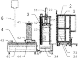
- FIG. 1 is a schematic diagram of an overall structure of the present disclosure.
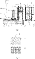
- FIG. 2 is a schematic diagram of a structure of a sample tray unit of the present disclosure.
- an automatic sample changing device for particle beam radiation samples provided by this embodiment includes a plurality of sample tray units 1 , a sample tray transporting unit 2 , a sample tray handling unit 3 , and a sample tray radiation stage unit 4 .
- the sample tray units 1 are configured to load samples 5 to be irradiated, and the sample tray transporting unit 2 is configured to carry and deliver a sample tray unit 1 to a radiation room.
- the sample tray handling unit 3 is arranged between the sample tray transporting unit 2 and the sample tray radiation stage unit 4 , and is configured to transfer the sample tray unit 1 on the sample tray transporting unit 2 to the sample tray radiation stage unit 4 or return the sample tray unit 1 on the sample tray radiation stage unit 4 back to the sample tray transporting unit 2 .
- the sample tray radiation stage unit 4 is configured to carry the sample tray unit 1 transferred by the sample tray handling unit 3 and move the samples 5 to be irradiated on the sample tray unit 1 to a particle beam radiation area 6 to receive radiation.
- the sample tray transporting unit 2 includes: a cart mechanism 2 . 1 , on which a plurality of layer rack mechanisms 2 . 2 arranged along in a height direction are provided for accommodating at least one layer of sample tray unit 1 ; a cart positioning mechanism 2 . 4 , on which the cart mechanism 2 . 1 is slidably arranged, wherein the cart mechanism 2 . 1 may be delivered and fixed at a designated position in the radiation room by the cart positioning mechanism 2 . 4 ; and a toggle clamp positioning mechanism 2 . 3 , which is arranged onto the layer rack mechanisms 2 . 2 and is configured to ensure that the sample tray units 1 do not slide during transportation.
- the sample tray handling unit 3 includes: a robot mechanism 3 . 1 , on which a sample tray grabbing bracket mechanism 3 . 2 is provided for grabbing and transferring a layer rack mechanism 2 . 2 or a sample tray unit 1 on the sample tray radiation stage unit 4 ; a robot height adjustment mechanism 3 . 3 , which is arranged at a handling base 3 . 4 along a direction of Z axis and connected with the robot mechanism 3 . 1 , and is configured to adjust a height in the Z axis for the robot mechanism 3 . 1 .
- the sample tray radiation stage unit 4 includes: a Y axis moving mechanism 4 . 3 , which is arranged at a radiation stage base 4 . 5 and extends along a direction of Y axis; an X axis moving mechanism 4 . 2 , which is slidably arranged on the Y axis moving mechanism 4 . 3 and extends along a direction of X axis; a radiation stage support mechanism 4 . 1 , a lower end of which is slidably arranged at the X axis moving mechanism 4 . 2 , and a upper end of which is configured to carry a sample tray unit 1 transferred by the robot mechanism 3 . 1 ; a radiation stage height adjustment mechanism 4 . 4 , which is arranged on the radiation stage support mechanism 4 . 1 and is configured to adjust a distance between the upper end of the radiation stage support mechanism 4 . 1 and a beam vacuum window.
- a radiation stage height adjustment mechanism 4 . 4 which is arranged on the radiation stage support mechanism 4 . 1 and is
- the sample tray units 1 are provided with groove-type trays 1 . 1 and scale-type trays 1 . 2 for loading varied types of samples 5 to be irradiated.
- grooves of a sample tray unit 1 may also be designed with its own size, shape or the like according to experimental requirements so as to be compatible with sample containers of various specifications, including petri dishes with a diameter of 30-60 mm, T12.5, T25 cell culture flasks, 0.2-50 mL centrifuge tubes, plant tissue culture flasks, and sample entities to be irradiated.
- the number of samples 5 to be irradiated that are accommodated in the sample tray unit 1 is 1-24.
- the layer rack mechanisms 2 . 2 on the cart mechanism 2 . 1 accommodate 1-10 layers of sample tray units 1 , and a distance between layers of sample tray units 1 can be adjusted according to specific conditions.
- one single cart mechanism 2 . 1 can accommodate hundreds of samples 5 to be irradiated, and radiation sample changing of hundreds of samples 5 to be irradiated can be completed by a staff entering and exiting the radiation room once to push in and out one cart mechanism 2 . 1 .
- the robot mechanism 3 . 1 may set a moving speed according to phase state of the samples 5 to be irradiated (such as solid samples or liquid samples).
- a moving speed for the solid samples is set to 50-120 mm/s, and a moving speed for the liquid samples is set to 10-60 mm/s so as to ensure that the samples will not pour or slosh during sample changing.
- a moving distance of the radiation stage support mechanism 4 . 1 in the X axis direction is ⁇ 200 mm to 500 mm
- a moving distance in the Y axis direction is ⁇ 100 mm to 300 mm
- movement may be carried out according to a preset coordinate so as to enable sequential irradiation of the samples
- a height adjustment range of the radiation stage height adjustment mechanism 4 . 4 in the Z axis direction is ⁇ 200 mm to 600 mm
- the sample tray radiation stage unit 4 is further equipped with a zero-point positioning function to enable beam monitoring and dose calibration.
- Embodiment 2 provided is an automatic sample changing method for particle beam irradiation samples, including the following steps 1 to 6.
- step 1 the sample tray radiation stage unit 4 is installed in front of the beam vacuum window.
- samples to be irradiated such as plant seeds, pollen, tissue pieces, microbial colonies and spores to be irradiated are placed into 24 petri dishes of 35 mm separately and then arranged together on one sample tray unit 1 , 10 sample tray units 1 like this are inserted into the layer rack mechanisms 2 . 2 of the cart mechanism 2 . 1 layer by layer and fixed with the toggle clamp positioning mechanism 2 . 3 , then, the cart mechanism 2 . 1 is pushed onto the cart positioning mechanism 2 . 4 to be delivered and fixed at a designated position in the radiation room.
- step 3 the robot mechanism 3 . 1 transfers, from the cart mechanism 2 . 1 , a sample tray unit 1 at a specific layer rack mechanism 2 . 2 to the radiation stage support mechanism 4 . 1 , where a selected moving speed is 100 mm/s; and the radiation stage support mechanism 4 . 1 adjusts, through the radiation stage height adjustment mechanism 4 . 4 , a distance between the beam vacuum window and the samples 5 to be irradiated to 800 mm.
- step 4 a position of the radiation stage support mechanism 4 . 1 is adjusted through the X axis moving mechanism 4 . 2 and the Y axis moving mechanism 4 . 3 so that all the samples 5 to be irradiated on the sample tray unit 1 arranged on the radiation stage support mechanism 4 . 1 move in sequence according to preset coordinates, and each of the samples 5 to be irradiated undergoes individual irradiation in sequence through an adopted medium-energy carbon ion beam of 80 MeV/u passing through the beam vacuum window and air layer.
- step 5 after all the samples 5 to be irradiated on the sample tray unit 1 are irradiated, the sample tray unit 1 is returned from the radiation stage support mechanism 4 . 1 to a designated layer rack mechanism 2 . 2 of the cart mechanism 2 . 1 by the sample tray handling unit 3 , where a selected moving speed is 100 mm/s.
- step 6 steps 3 to 5 are repeated until irradiation of all the samples 5 to be irradiated on the cart mechanism 2 . 1 are completed, and then the staff enters the radiation room and pushes the cart mechanism 2 . 1 out of the radiation room for the next round of sample changing.
- Embodiment 3 provided is an automatic sample changing method for particle beam irradiation samples, including the following steps 1 to 6.
- step 1 the sample tray radiation stage unit 4 is installed in front of the beam vacuum window.
- step 2 samples to be irradiated, such as plant seeds, pollen, tissue pieces, microbial colonies and spores to be irradiated are placed into 12 petri dishes of 60 mm separately and then arranged together on one sample tray unit, 5 sample tray units 1 like this are inserted into the layer rack mechanisms 2 . 2 of the cart mechanism 2 . 1 layer by layer and fixed with the toggle clamp positioning mechanism 2 . 3 , then, the cart mechanism 2 . 1 is pushed onto the cart positioning mechanism 2 . 4 to be delivered and fixed at a designated position in the radiation room.
- step 3 the robot mechanism 3 . 1 transfers, from the cart mechanism 2 . 1 , a sample tray unit 1 at a specific layer rack mechanism 2 . 2 to the radiation stage support mechanism 4 . 1 , where a selected moving speed is 100 mm/s; and the radiation stage support mechanism 4 . 1 adjusts, through the radiation stage height adjustment mechanism 4 . 4 , a distance between the beam vacuum window and the samples 5 to be irradiated to 1000 mm.
- step 4 a position of the radiation stage support mechanism 4 . 1 is adjusted through the X axis moving mechanism 4 . 2 and the Y axis moving mechanism 4 . 3 so that all the samples 5 to be irradiated on the sample tray unit 1 arranged on the radiation stage support mechanism 4 . 1 move in sequence according to preset coordinates, and each of the samples 5 to be irradiated undergoes individual irradiation in sequence through an adopted high-energy argon ion beam of 50 MeV/u passing through the beam vacuum window and air layer.
- step 5 after all the samples 5 to be irradiated on the sample tray unit 1 are irradiated, the sample tray unit 1 is returned from the radiation stage support mechanism 4 . 1 to a designated layer rack mechanism 2 . 2 of the cart mechanism 2 . 1 by the sample tray handling unit 3 , where a selected moving speed is 100 mm/s.
- step 6 steps 3 to 5 are repeated until irradiation of all the samples 5 to be irradiated on the cart mechanism 2 . 1 are completed, and the staff enters the radiation room and pushes the cart mechanism 2 . 1 out of the radiation room for the next round of sample changing.
- Embodiment 4 provided is an automatic sample changing method for particle beam irradiation samples, including the following steps 1 to 6.
- step 1 the sample tray radiation stage unit 4 is installed in front of the beam vacuum window.
- liquid samples 5 to be irradiated such as mammalian adherent cells, suspension cells, plant algae liquid, microbial bacteria liquid to be irradiated are placed into 24 petri dishes of 35 mm separately and then arranged together on one sample tray unit, 10 sample tray units 1 like this are inserted into the layer rack mechanisms 2 . 2 of the cart mechanism 2 . 1 layer by layer and fixed with the toggle clamp positioning mechanism 2 . 3 , then, the cart mechanism 2 . 1 is pushed onto the cart positioning mechanism 2 . 4 to be delivered and fixed at a designated position in the radiation room.
- mammalian adherent cells, suspension cells, plant algae liquid, microbial bacteria liquid to be irradiated are placed into 24 petri dishes of 35 mm separately and then arranged together on one sample tray unit, 10 sample tray units 1 like this are inserted into the layer rack mechanisms 2 . 2 of the cart mechanism 2 . 1 layer by layer and fixed with the toggle clamp positioning mechanism 2 . 3 , then, the cart mechanism 2 . 1 is pushed onto the
- step 3 the robot mechanism 3 . 1 transfers, from the cart mechanism 2 . 1 , a sample tray unit 1 at a specific layer rack mechanism 2 . 2 to the radiation stage support mechanism 4 . 1 , where a selected moving speed is 50 mm/s; and the radiation stage support mechanism 4 . 1 adjusts, through the radiation stage height adjustment mechanism 4 . 4 , a distance between the beam vacuum window and the samples 5 to be irradiated to 800 mm.
- step 4 a position of the radiation stage support mechanism 4 . 1 is adjusted through the X axis moving mechanism 4 . 2 and the Y axis moving mechanism 4 . 3 so that all the samples 5 to be irradiated on the sample tray unit 1 arranged on the radiation stage support mechanism 4 . 1 move in sequence according to preset coordinates, and each of the samples 5 to be irradiated undergoes individual irradiation in sequence through an adopted medium-energy carbon ion beam of 80 MeV/u passing through the beam vacuum window and air layer.
- step 5 after all the samples 5 to be irradiated on the sample tray unit 1 are irradiated, the sample tray unit 1 is returned from the radiation stage support mechanism 4 . 1 to a designated layer rack mechanism 2 . 2 of the cart mechanism 2 . 1 by the sample tray handling unit 3 , where a selected moving speed is 50 mm/s.
- step 6 steps 3 to 5 are repeated until irradiation of all the samples 5 to be irradiated on the cart mechanism 2 . 1 are completed, and then the staff enters the radiation room and pushes the cart mechanism 2 . 1 out of the radiation room for the next round of sample changing.
- Embodiment 5 provided is an automatic sample changing method for particle beam irradiation samples, including the following steps 1 to 6.
- step 1 the sample tray radiation stage unit 4 is installed in front of the beam vacuum window.
- step 2 12 samples 5 to be irradiated, such as plant tubers, rhizomes, branches, mice and rats to be irradiated are placed directly on a sample tray unit 1 , respectively, 10 sample tray units 1 like this are inserted into the layer rack mechanisms 2 . 2 of the cart mechanism 2 . 1 layer by layer and fixed with the toggle clamp positioning mechanism 2 . 3 , then, the cart mechanism 2 . 1 is pushed onto the cart positioning mechanism 2 . 4 to be delivered and fixed at a designated position in the radiation room.
- 12 samples 5 to be irradiated such as plant tubers, rhizomes, branches, mice and rats to be irradiated are placed directly on a sample tray unit 1 , respectively, 10 sample tray units 1 like this are inserted into the layer rack mechanisms 2 . 2 of the cart mechanism 2 . 1 layer by layer and fixed with the toggle clamp positioning mechanism 2 . 3 , then, the cart mechanism 2 . 1 is pushed onto the cart positioning mechanism 2 . 4 to be delivered and fixed at a
- step 3 the robot mechanism 3 . 1 transfers, from the cart mechanism 2 . 1 , a sample tray unit 1 at a specific layer rack mechanism 2 . 2 to the radiation stage support mechanism 4 . 1 , where a selected moving speed is 100 mm/s; and the radiation stage support mechanism 4 . 1 adjusts, through the radiation stage height adjustment mechanism 4 . 4 , a distance between the beam vacuum window and the samples 5 to be irradiated to 800 mm.
- step 4 a position of the radiation stage support mechanism 4 . 1 is adjusted through the X axis moving mechanism 4 . 2 and the Y axis moving mechanism 4 . 3 so that all the samples 5 to be irradiated on the sample tray unit 1 arranged on the radiation stage support mechanism 4 . 1 move in sequence according to preset coordinates, and each of the samples 5 to be irradiated undergoes individual irradiation in sequence through an adopted medium-energy carbon ion beam of 80 MeV/u passing through the beam vacuum window and air layer.
- step 5 after all the samples 5 to be irradiated on the sample tray unit 1 are irradiated, the sample tray unit 1 is returned from the radiation stage support mechanism 4 . 1 to a designated layer rack mechanism 2 . 2 of the cart mechanism 2 . 1 by the sample tray handling unit 3 , where a selected moving speed is 100 mm/s.
- step 6 steps 3 to 5 are repeated until irradiation of all the samples 5 to be irradiated on the cart mechanism 2 . 1 are completed, and then the staff enters the radiation room and pushes the cart mechanism 2 . 1 out of the radiation room for the next round of sample changing.
- Embodiment 6 provided is an automatic sample changing method for particle beam irradiation samples, including the following steps 1 to 6.
- step 1 the sample tray radiation stage unit 4 is installed in front of the beam vacuum window.
- step 2 10 samples to be irradiated of powder pellets of epipodophyllotoxins are placed directly on a sample tray unit 1 , 5 sample tray units 1 like this are inserted into the layer rack mechanism 2 . 2 of the cart mechanism 2 . 1 layer by layer and fixed with the toggle clamp positioning mechanism 2 . 3 , then, the cart mechanism 2 . 1 is pushed onto the cart positioning mechanism 2 . 4 to be delivered and fixed at a designated position in the radiation room.
- step 3 the robot mechanism 3 . 1 transfers, from the cart mechanism 2 . 1 , a sample tray unit 1 at a specific layer rack mechanism 2 . 2 to the radiation stage support mechanism 4 . 1 , where a selected moving speed is 100 mm/s; and the radiation stage support mechanism 4 . 1 adjusts, through the radiation stage height adjustment mechanism 4 . 4 , a distance between the beam vacuum window and the samples 5 to be irradiated to 800 mm.
- step 4 a position of the radiation stage support mechanism 4 . 1 is adjusted through the X axis moving mechanism 4 . 2 and the Y axis moving mechanism 4 . 3 so that all the samples 5 to be irradiated on the sample tray unit 1 arranged on the radiation stage support mechanism 4 . 1 move in sequence according to preset coordinates, and each of the samples 5 to be irradiated undergoes individual irradiation in sequence through an adopted medium-energy carbon ion beam of 80 MeV/u passing through the beam vacuum window and air layer.
- step 5 after all the samples 5 to be irradiated on the sample tray unit 1 are irradiated, the sample tray unit 1 is returned from the radiation stage support mechanism 4 . 1 to a designated layer rack mechanism 2 . 2 of the cart mechanism 2 . 1 by the sample tray handling unit 3 , where a selected moving speed is 100 mm/s.
- step 6 steps 3 to 5 are repeated until irradiation of all the samples 5 to be irradiated on the cart mechanism 2 . 1 are completed, and then the staff enters the radiation room and pushes the cart mechanism 2 . 1 out of the radiation room for the next round of sample changing.
Landscapes
- General Physics & Mathematics (AREA)
- Health & Medical Sciences (AREA)
- Life Sciences & Earth Sciences (AREA)
- Physics & Mathematics (AREA)
- Spectroscopy & Molecular Physics (AREA)
- Molecular Biology (AREA)
- High Energy & Nuclear Physics (AREA)
- Analytical Chemistry (AREA)
- Immunology (AREA)
- Pathology (AREA)
- General Health & Medical Sciences (AREA)
- Biochemistry (AREA)
- Chemical & Material Sciences (AREA)
- Engineering & Computer Science (AREA)
- Robotics (AREA)
- Sampling And Sample Adjustment (AREA)
Abstract
Description
- The present disclosure relates to an automatic sample changing device and method, in particular to an automatic sample changing device and method for particle beam irradiation samples.
- With development of nuclear science and nuclear technology, applications of radiation in biology and material science have become increasingly widespread. In the aspect of biology, mutation breeding of plants and microorganisms can be carried out. Compared with conventional breeding, radiation mutation breeding has advantages, such as simplicity, safety, high mutation rate, and saving manpower and material resources, and it has become an effective approach for traits improvement and germ plasm innovation. In addition, radiation can also be employed in particle beam cancer therapy and space biology research to carry out tumor radiotherapy and ground simulation of manned spaceflight biological effect. Radiation can also applied to carry out research of radiated molecular modification of drug molecules, which is beneficial for development of new drug molecules. In the aspect of material science, researches can be carried out in many fields, such as material modification, radiation resistance, nanomaterial preparation, and radiation tolerance of semiconductor components.
- Different from electromagnetic radiation, particle beam radiation has a mode of action that is considerably different from target substance, and has a characteristic of strong radiation effect. A particle beam contains leptons and hadrons. The leptons may be electrons or positrons, and the hadrons include protons, light ions (such as helium ions), and heavy ions (such as carbon ions, oxygen ions, neon ions, argon ions, and iron ions, etc.). An energy range of particle beams may be ranged from thousands of electron volts to millions of or even gigas of electron volts that is a quantity close to the speed of light. As one of emerging sources of physical mutagenesis, particle beams are playing an increasingly important role in radiation mutagenesis breeding. Compared with traditional photon radiation, such as y-rays and X-rays, particle beam radiation mutation breeding has characteristics of high mutation efficiency, wide mutation spectrum, and short stable period, and is thereby widely applied on development of new varieties/new bacterial strains and creation of germplasm resources further and further. In the field of tumor therapy, particle beams have a characteristic of high relative-biological effectiveness of target area. In a process of penetrating through or injecting into a compound, a particle beam has characteristics of energy deposition and mass deposition, which may cause atomic or molecular damage to enable structure rearrangement of some molecules and may further form new molecular groups to enable change of physical properties and chemical properties of the original material. Thus, particle beams have a wide range of usages in fundamental and application researches of materials science. Particle beams are generally obtained by devices, such as reactors and particle accelerators.
- An existing rotary tray sample changing system has drawbacks of low throughput and low efficiency, thereby failing to meet increasing demands of domestic users. The rotary tray sample changing system provides few samples to be changed at one time, leading to more times of changing of samples so that a waste of beam time has been resulted because to sample changing of rotary trays. At the same time, a high-energy particle accelerator has a high operating cost, where one hour of operation costs tens of thousands of RMB. Therefore, it is extremely important to improve efficiency of sample changing and increase a throughput of sample changing. In order to make full use of a beam generated by the accelerator and reduce a waste of costly beam, sufficient attention should be paid to the sample changing system of radiation samples. Only significant improvement of sample changing efficiency and increase of sample throughput at once sample changing, can biological and material samples undergoing particle beam irradiation meet the need of industrialization.
- In view of the above problems, an objective of the present disclosure is to provide an automatic sample changing device and method for particle beam radiation samples so as to enable automatic changing of sample trays to replace manual sample changing, avoid waiting for an environmental radiation dose in a radiation room to drop to a safety range, so that beam time of a particle beam can be saved, thereby improving an utilization efficiency of the beam.
- In order to achieve these above, an embodiment of the present disclosure provides an automatic sample changing device for particle beam radiation samples, including sample tray units, a sample tray transporting unit, a sample tray handling unit, and a sample tray radiation stage unit, wherein the sample tray units are configured to load samples to be irradiated, and the sample tray transporting unit is configured to carry and deliver a sample tray unit to a radiation room; the sample tray handling unit is arranged between the sample tray transporting unit and the sample tray radiation stage unit, and is configured to transfer the sample tray unit on the sample tray transporting unit to the sample tray radiation stage unit or return the sample tray unit on the sample tray radiation stage unit back to the sample tray transporting unit; and the sample tray radiation stage unit is configured to carry the sample tray unit transferred by the sample tray handling unit and move the samples to be irradiated in the sample tray unit to a particle beam radiation area to receive radiation.
- In the automatic sample changing device, preferably, the sample tray transporting unit includes: a cart mechanism, on which layer rack mechanisms arranged along in a height direction are provided for accommodating at least one layer of sample tray unit; a cart positioning mechanism, on which the cart mechanism is slidably arranged, wherein the cart mechanism is delivered and fixed in a designated position in the radiation room by the cart positioning mechanism; and a toggle clamp positioning mechanism, which is arranged onto the layer rack mechanisms and is configured to ensure that the sample tray unit do not slide during transportation.
- In the automatic sample changing device, preferably, the sample tray handling unit includes: a robot mechanism, on which a sample tray grabbing bracket mechanism is provided for grabbing and transferring a layer rack mechanism or a sample tray unit on the sample tray radiation stage unit; and a robot height adjustment mechanism, which is arranged at a handling base along a direction of Z axis and connected with the robot mechanism, and is configured to adjust the height in the Z axis for the robot mechanism.
- In the automatic sample changing device, preferably, the sample tray radiation stage unit includes: a Y axis moving mechanism, which is arranged on a radiation stage base and extends along a direction of Y axis; an X axis moving mechanism, which is slidably arranged on the Y axis moving mechanism and extends along a direction of X axis; a radiation stage support mechanism, a lower end of which is slidably arranged at the X axis moving mechanism, and a upper end of which is configured to carry the sample tray unit transferred by the robot mechanism; a radiation stage height adjustment mechanism, which is arranged on the radiation stage support mechanism, and is configured to adjust a distance between the upper end of the radiation stage support mechanism and a beam vacuum window.
- In the automatic sample changing device, preferably, the sample tray units are provided with groove-type trays and scale-type trays for loading different types of samples to be irradiated.
- In the automatic sample changing device, preferably, the number of samples to be irradiated that are accommodated in the sample tray unit is 1-24; the layer rack mechanisms on the cart mechanism accommodate 1-10 layers of sample tray units; the robot mechanism sets a moving speed according to phase state of the samples to be irradiated: a moving speed for solid samples is set to 50-120 mm/s, and a moving speed for liquid samples is set to 10-60 mm/s; a moving distance of the radiation stage support mechanism in the X axis direction is −200 mm to 500 mm, and a moving distance in the Y axis direction is −100 mm to 300 mm; a height adjustment range of the radiation stage height adjustment mechanism in the Z axis direction is −200 mm to 600 mm; and the sample tray radiation stage unit is equipped with a zero-point positioning function.
- Provided is an automatic sample changing method for samples to be irradiated by particle beam irradiation, which uses the above automatic sample changing device, characterized in that the method includes steps of:
-
step 1, installing the sample tray radiation stage unit in front of the beam vacuum window; -
step 2, placing the samples to be irradiated in the sample tray units, inserting the sample tray units into the layer rack mechanism of the cart mechanism layer by layer and fixing the sample tray units with the toggle clamp positioning mechanism, and pushing the cart mechanism onto the cart positioning mechanism to deliver and fixe the cart mechanism at the designated position in the radiation room; -
step 3, transferring, by the robot mechanism, a sample tray unit at a specific layer rack mechanism from the cart mechanism to the radiation stage support mechanism, and adjusting, by the radiation stage height adjustment mechanism according to particle energy and a range of a radiation, a distance between the beam vacuum window and the samples to be irradiated to enable the radiation in an optimum condition; -
step 4, adjusting, by the X axis moving mechanism and the Y axis moving mechanism, a position of the radiation stage support mechanism so that all samples to be irradiated in the sample tray unit arranged on the radiation stage support mechanism move in sequence according to preset coordinates, and subjecting each of the samples to be irradiated to individual irradiation in sequence by a particle beam passing through the vacuum window and air layer; -
step 5, after all samples to be irradiated in the sample tray unit are irradiated, returning, by the sample tray handling unit, the sample tray unit from the radiation stage support mechanism to a designated layer rack mechanism of the cart mechanism; and -
step 6, repeatingsteps 3 to 5 until irradiation of all the samples to be irradiated on the cart mechanism are completed, and pushing the cart mechanism out of the radiation room for a next round of sample changing. - According to the automatic sample changing method, preferably, the particle beam includes nuclear particles and/or charged particles with an energy range of 8-400 MeV/u.
- In the automatic sample changing method, preferably, the sample to be irradiated is irradiated under an atmospheric condition.
- According to the automatic sample changing method, preferably, the sample to be irradiated includes plant seeds, tissue cultured seedlings, tissue pieces, roots, stems, leaves, buds, pollen, algae, spores, microbial fluids, colonies, spores, mammalian adherence, suspension culture cells, small animals, compounds, metals or non-metals.
- On basis of these above, the present disclosure has the following advantages: 1. the sample tray units, the sample tray transporting unit, the sample tray handling unit and the sample tray radiation stage unit of the present disclosure cooperate with each other to enable automatic sample changing of the samples to be irradiated, so that an throughput of sample changing is significantly increased, and a waste of beam caused by staff frequently entering and exiting the irradiation room to change samples is greatly reduced, beam time of the particle beam is saved, and efficient sample changing for radiation of the samples to be irradiated is realized. 2. It has been verified through many times practice that the present disclosure is applicable to the samples to be irradiated by particle beam radiation, which has advantages of a high throughput and an applicability of radiation under the atmosphere. An operator can implement radiation sample changing of hundreds of samples to be irradiated through entering and exiting the radiation room only once. Sample changing for hundreds of samples to be irradiated can be completed per hour, which is completely applicable to a high-efficiency radiation treatment of the samples to be irradiated by particle beams, so that efficiency of sample changing is greatly improved and a shortcoming of high cost of high-energy particle accelerators is overcome, promoting industrialization of the particle beam radiation of biology and material samples.
-
FIG. 1 is a schematic diagram of an overall structure of the present disclosure; and -
FIG. 2 is a schematic diagram of a structure of a sample tray unit of the present disclosure. - The preferred embodiments of the present disclosure will be described in detail below with reference to the accompanying drawings in order to understand the purpose, features and advantages of the present disclosure in a clear manner. It should be understood that the embodiments shown in the drawings do not intent to construct limitation to the scope of the present disclosure, but merely to illustrate the essential spirit of the technical solution of the present disclosure.
- Embodiment 1: as shown in
FIGS. 1 and 2 , an automatic sample changing device for particle beam radiation samples provided by this embodiment includes a plurality ofsample tray units 1, a sampletray transporting unit 2, a sampletray handling unit 3, and a sample trayradiation stage unit 4. Thesample tray units 1 are configured to loadsamples 5 to be irradiated, and the sampletray transporting unit 2 is configured to carry and deliver asample tray unit 1 to a radiation room. The sampletray handling unit 3 is arranged between the sampletray transporting unit 2 and the sample trayradiation stage unit 4, and is configured to transfer thesample tray unit 1 on the sampletray transporting unit 2 to the sample trayradiation stage unit 4 or return thesample tray unit 1 on the sample trayradiation stage unit 4 back to the sampletray transporting unit 2. The sample trayradiation stage unit 4 is configured to carry thesample tray unit 1 transferred by the sampletray handling unit 3 and move thesamples 5 to be irradiated on thesample tray unit 1 to a particlebeam radiation area 6 to receive radiation. - In this embodiment, preferably, the sample
tray transporting unit 2 includes: a cart mechanism 2.1, on which a plurality of layer rack mechanisms 2.2 arranged along in a height direction are provided for accommodating at least one layer ofsample tray unit 1; a cart positioning mechanism 2.4, on which the cart mechanism 2.1 is slidably arranged, wherein the cart mechanism 2.1 may be delivered and fixed at a designated position in the radiation room by the cart positioning mechanism 2.4; and a toggle clamp positioning mechanism 2.3, which is arranged onto the layer rack mechanisms 2.2 and is configured to ensure that thesample tray units 1 do not slide during transportation. - In this embodiment, preferably, the sample
tray handling unit 3 includes: a robot mechanism 3.1, on which a sample tray grabbing bracket mechanism 3.2 is provided for grabbing and transferring a layer rack mechanism 2.2 or asample tray unit 1 on the sample trayradiation stage unit 4; a robot height adjustment mechanism 3.3, which is arranged at a handling base 3.4 along a direction of Z axis and connected with the robot mechanism 3.1, and is configured to adjust a height in the Z axis for the robot mechanism 3.1. - In this embodiment, preferably, the sample tray
radiation stage unit 4 includes: a Y axis moving mechanism 4.3, which is arranged at a radiation stage base 4.5 and extends along a direction of Y axis; an X axis moving mechanism 4.2, which is slidably arranged on the Y axis moving mechanism 4.3 and extends along a direction of X axis; a radiation stage support mechanism 4.1, a lower end of which is slidably arranged at the X axis moving mechanism 4.2, and a upper end of which is configured to carry asample tray unit 1 transferred by the robot mechanism 3.1; a radiation stage height adjustment mechanism 4.4, which is arranged on the radiation stage support mechanism 4.1 and is configured to adjust a distance between the upper end of the radiation stage support mechanism 4.1 and a beam vacuum window. - In this embodiment, preferably, the
sample tray units 1 are provided with groove-type trays 1.1 and scale-type trays 1.2 for loading varied types ofsamples 5 to be irradiated. - In this embodiment, preferably, grooves of a
sample tray unit 1 may also be designed with its own size, shape or the like according to experimental requirements so as to be compatible with sample containers of various specifications, including petri dishes with a diameter of 30-60 mm, T12.5, T25 cell culture flasks, 0.2-50 mL centrifuge tubes, plant tissue culture flasks, and sample entities to be irradiated. - In this embodiment, preferably, the number of
samples 5 to be irradiated that are accommodated in thesample tray unit 1 is 1-24. - In this embodiment, preferably, the layer rack mechanisms 2.2 on the cart mechanism 2.1 accommodate 1-10 layers of
sample tray units 1, and a distance between layers ofsample tray units 1 can be adjusted according to specific conditions. In this way, one single cart mechanism 2.1 can accommodate hundreds ofsamples 5 to be irradiated, and radiation sample changing of hundreds ofsamples 5 to be irradiated can be completed by a staff entering and exiting the radiation room once to push in and out one cart mechanism 2.1. - In this embodiment, preferably, the robot mechanism 3.1 may set a moving speed according to phase state of the
samples 5 to be irradiated (such as solid samples or liquid samples). A moving speed for the solid samples is set to 50-120 mm/s, and a moving speed for the liquid samples is set to 10-60 mm/s so as to ensure that the samples will not pour or slosh during sample changing. - In this embodiment, preferably, a moving distance of the radiation stage support mechanism 4.1 in the X axis direction is −200 mm to 500 mm, and a moving distance in the Y axis direction is −100 mm to 300 mm, and movement may be carried out according to a preset coordinate so as to enable sequential irradiation of the samples; a height adjustment range of the radiation stage height adjustment mechanism 4.4 in the Z axis direction is −200 mm to 600 mm; at the same time, the sample tray
radiation stage unit 4 is further equipped with a zero-point positioning function to enable beam monitoring and dose calibration. - Embodiment 2: provided is an automatic sample changing method for particle beam irradiation samples, including the following
steps 1 to 6. - In
step 1, the sample trayradiation stage unit 4 is installed in front of the beam vacuum window. - In
step 2, samples to be irradiated, such as plant seeds, pollen, tissue pieces, microbial colonies and spores to be irradiated are placed into 24 petri dishes of 35 mm separately and then arranged together on onesample tray unit 1, 10sample tray units 1 like this are inserted into the layer rack mechanisms 2.2 of the cart mechanism 2.1 layer by layer and fixed with the toggle clamp positioning mechanism 2.3, then, the cart mechanism 2.1 is pushed onto the cart positioning mechanism 2.4 to be delivered and fixed at a designated position in the radiation room. - In
step 3, the robot mechanism 3.1 transfers, from the cart mechanism 2.1, asample tray unit 1 at a specific layer rack mechanism 2.2 to the radiation stage support mechanism 4.1, where a selected moving speed is 100 mm/s; and the radiation stage support mechanism 4.1 adjusts, through the radiation stage height adjustment mechanism 4.4, a distance between the beam vacuum window and thesamples 5 to be irradiated to 800 mm. - In
step 4, a position of the radiation stage support mechanism 4.1 is adjusted through the X axis moving mechanism 4.2 and the Y axis moving mechanism 4.3 so that all thesamples 5 to be irradiated on thesample tray unit 1 arranged on the radiation stage support mechanism 4.1 move in sequence according to preset coordinates, and each of thesamples 5 to be irradiated undergoes individual irradiation in sequence through an adopted medium-energy carbon ion beam of 80 MeV/u passing through the beam vacuum window and air layer. - In
step 5, after all thesamples 5 to be irradiated on thesample tray unit 1 are irradiated, thesample tray unit 1 is returned from the radiation stage support mechanism 4.1 to a designated layer rack mechanism 2.2 of the cart mechanism 2.1 by the sampletray handling unit 3, where a selected moving speed is 100 mm/s. - In
step 6,steps 3 to 5 are repeated until irradiation of all thesamples 5 to be irradiated on the cart mechanism 2.1 are completed, and then the staff enters the radiation room and pushes the cart mechanism 2.1 out of the radiation room for the next round of sample changing. - Embodiment 3: provided is an automatic sample changing method for particle beam irradiation samples, including the following
steps 1 to 6. - In
step 1, the sample trayradiation stage unit 4 is installed in front of the beam vacuum window. - In
step 2, samples to be irradiated, such as plant seeds, pollen, tissue pieces, microbial colonies and spores to be irradiated are placed into 12 petri dishes of 60 mm separately and then arranged together on one sample tray unit, 5sample tray units 1 like this are inserted into the layer rack mechanisms 2.2 of the cart mechanism 2.1 layer by layer and fixed with the toggle clamp positioning mechanism 2.3, then, the cart mechanism 2.1 is pushed onto the cart positioning mechanism 2.4 to be delivered and fixed at a designated position in the radiation room. - In
step 3, the robot mechanism 3.1 transfers, from the cart mechanism 2.1, asample tray unit 1 at a specific layer rack mechanism 2.2 to the radiation stage support mechanism 4.1, where a selected moving speed is 100 mm/s; and the radiation stage support mechanism 4.1 adjusts, through the radiation stage height adjustment mechanism 4.4, a distance between the beam vacuum window and thesamples 5 to be irradiated to 1000 mm. - In
step 4, a position of the radiation stage support mechanism 4.1 is adjusted through the X axis moving mechanism 4.2 and the Y axis moving mechanism 4.3 so that all thesamples 5 to be irradiated on thesample tray unit 1 arranged on the radiation stage support mechanism 4.1 move in sequence according to preset coordinates, and each of thesamples 5 to be irradiated undergoes individual irradiation in sequence through an adopted high-energy argon ion beam of 50 MeV/u passing through the beam vacuum window and air layer. - In
step 5, after all thesamples 5 to be irradiated on thesample tray unit 1 are irradiated, thesample tray unit 1 is returned from the radiation stage support mechanism 4.1 to a designated layer rack mechanism 2.2 of the cart mechanism 2.1 by the sampletray handling unit 3, where a selected moving speed is 100 mm/s. - In
step 6,steps 3 to 5 are repeated until irradiation of all thesamples 5 to be irradiated on the cart mechanism 2.1 are completed, and the staff enters the radiation room and pushes the cart mechanism 2.1 out of the radiation room for the next round of sample changing. - Embodiment 4: provided is an automatic sample changing method for particle beam irradiation samples, including the following
steps 1 to 6. - In
step 1, the sample trayradiation stage unit 4 is installed in front of the beam vacuum window. - In
step 2,liquid samples 5 to be irradiated, such as mammalian adherent cells, suspension cells, plant algae liquid, microbial bacteria liquid to be irradiated are placed into 24 petri dishes of 35 mm separately and then arranged together on one sample tray unit, 10sample tray units 1 like this are inserted into the layer rack mechanisms 2.2 of the cart mechanism 2.1 layer by layer and fixed with the toggle clamp positioning mechanism 2.3, then, the cart mechanism 2.1 is pushed onto the cart positioning mechanism 2.4 to be delivered and fixed at a designated position in the radiation room. - In
step 3, the robot mechanism 3.1 transfers, from the cart mechanism 2.1, asample tray unit 1 at a specific layer rack mechanism 2.2 to the radiation stage support mechanism 4.1, where a selected moving speed is 50 mm/s; and the radiation stage support mechanism 4.1 adjusts, through the radiation stage height adjustment mechanism 4.4, a distance between the beam vacuum window and thesamples 5 to be irradiated to 800 mm. - In
step 4, a position of the radiation stage support mechanism 4.1 is adjusted through the X axis moving mechanism 4.2 and the Y axis moving mechanism 4.3 so that all thesamples 5 to be irradiated on thesample tray unit 1 arranged on the radiation stage support mechanism 4.1 move in sequence according to preset coordinates, and each of thesamples 5 to be irradiated undergoes individual irradiation in sequence through an adopted medium-energy carbon ion beam of 80 MeV/u passing through the beam vacuum window and air layer. - In
step 5, after all thesamples 5 to be irradiated on thesample tray unit 1 are irradiated, thesample tray unit 1 is returned from the radiation stage support mechanism 4.1 to a designated layer rack mechanism 2.2 of the cart mechanism 2.1 by the sampletray handling unit 3, where a selected moving speed is 50 mm/s. - In
step 6,steps 3 to 5 are repeated until irradiation of all thesamples 5 to be irradiated on the cart mechanism 2.1 are completed, and then the staff enters the radiation room and pushes the cart mechanism 2.1 out of the radiation room for the next round of sample changing. - Embodiment 5: provided is an automatic sample changing method for particle beam irradiation samples, including the following
steps 1 to 6. - In
step 1, the sample trayradiation stage unit 4 is installed in front of the beam vacuum window. - In
step 2, 12samples 5 to be irradiated, such as plant tubers, rhizomes, branches, mice and rats to be irradiated are placed directly on asample tray unit 1, respectively, 10sample tray units 1 like this are inserted into the layer rack mechanisms 2.2 of the cart mechanism 2.1 layer by layer and fixed with the toggle clamp positioning mechanism 2.3, then, the cart mechanism 2.1 is pushed onto the cart positioning mechanism 2.4 to be delivered and fixed at a designated position in the radiation room. - In
step 3, the robot mechanism 3.1 transfers, from the cart mechanism 2.1, asample tray unit 1 at a specific layer rack mechanism 2.2 to the radiation stage support mechanism 4.1, where a selected moving speed is 100 mm/s; and the radiation stage support mechanism 4.1 adjusts, through the radiation stage height adjustment mechanism 4.4, a distance between the beam vacuum window and thesamples 5 to be irradiated to 800 mm. - In
step 4, a position of the radiation stage support mechanism 4.1 is adjusted through the X axis moving mechanism 4.2 and the Y axis moving mechanism 4.3 so that all thesamples 5 to be irradiated on thesample tray unit 1 arranged on the radiation stage support mechanism 4.1 move in sequence according to preset coordinates, and each of thesamples 5 to be irradiated undergoes individual irradiation in sequence through an adopted medium-energy carbon ion beam of 80 MeV/u passing through the beam vacuum window and air layer. - In
step 5, after all thesamples 5 to be irradiated on thesample tray unit 1 are irradiated, thesample tray unit 1 is returned from the radiation stage support mechanism 4.1 to a designated layer rack mechanism 2.2 of the cart mechanism 2.1 by the sampletray handling unit 3, where a selected moving speed is 100 mm/s. - In
step 6,steps 3 to 5 are repeated until irradiation of all thesamples 5 to be irradiated on the cart mechanism 2.1 are completed, and then the staff enters the radiation room and pushes the cart mechanism 2.1 out of the radiation room for the next round of sample changing. - Embodiment 6: provided is an automatic sample changing method for particle beam irradiation samples, including the following
steps 1 to 6. - In
step 1, the sample trayradiation stage unit 4 is installed in front of the beam vacuum window. - In
step 2, 10 samples to be irradiated of powder pellets of epipodophyllotoxins are placed directly on asample tray unit sample tray units 1 like this are inserted into the layer rack mechanism 2.2 of the cart mechanism 2.1 layer by layer and fixed with the toggle clamp positioning mechanism 2.3, then, the cart mechanism 2.1 is pushed onto the cart positioning mechanism 2.4 to be delivered and fixed at a designated position in the radiation room. - In
step 3, the robot mechanism 3.1 transfers, from the cart mechanism 2.1, asample tray unit 1 at a specific layer rack mechanism 2.2 to the radiation stage support mechanism 4.1, where a selected moving speed is 100 mm/s; and the radiation stage support mechanism 4.1 adjusts, through the radiation stage height adjustment mechanism 4.4, a distance between the beam vacuum window and thesamples 5 to be irradiated to 800 mm. - In
step 4, a position of the radiation stage support mechanism 4.1 is adjusted through the X axis moving mechanism 4.2 and the Y axis moving mechanism 4.3 so that all thesamples 5 to be irradiated on thesample tray unit 1 arranged on the radiation stage support mechanism 4.1 move in sequence according to preset coordinates, and each of thesamples 5 to be irradiated undergoes individual irradiation in sequence through an adopted medium-energy carbon ion beam of 80 MeV/u passing through the beam vacuum window and air layer. - In
step 5, after all thesamples 5 to be irradiated on thesample tray unit 1 are irradiated, thesample tray unit 1 is returned from the radiation stage support mechanism 4.1 to a designated layer rack mechanism 2.2 of the cart mechanism 2.1 by the sampletray handling unit 3, where a selected moving speed is 100 mm/s. - In
step 6,steps 3 to 5 are repeated until irradiation of all thesamples 5 to be irradiated on the cart mechanism 2.1 are completed, and then the staff enters the radiation room and pushes the cart mechanism 2.1 out of the radiation room for the next round of sample changing. - The foregoing embodiments are only used to illustrate the present disclosure, where a structure, a connection mode, and a manufacturing process of each component in these embodiments may be modified. Any equivalent transformation and improvement implemented based on the technical solution of the present disclosure should not be excluded out of the protection scope of the present disclosure.
Claims (10)
Applications Claiming Priority (3)
| Application Number | Priority Date | Filing Date | Title |
|---|---|---|---|
| CN201910171417.7A CN109917446B (en) | 2019-03-07 | 2019-03-07 | Automatic sample changing device and method for particle beam radiation sample |
| CN201910171417.7 | 2019-03-07 | ||
| PCT/CN2020/079125 WO2020177770A1 (en) | 2019-03-07 | 2020-03-13 | Automatic sample-changing device and method for particle beam radiation sample |
Publications (2)
| Publication Number | Publication Date |
|---|---|
| US20220179110A1 true US20220179110A1 (en) | 2022-06-09 |
| US12013505B2 US12013505B2 (en) | 2024-06-18 |
Family
ID=66963749
Family Applications (1)
| Application Number | Title | Priority Date | Filing Date |
|---|---|---|---|
| US17/436,191 Active 2041-03-06 US12013505B2 (en) | 2019-03-07 | 2020-03-13 | Automatic sample-changing device and method for particle beam radiation samples |
Country Status (3)
| Country | Link |
|---|---|
| US (1) | US12013505B2 (en) |
| CN (1) | CN109917446B (en) |
| WO (1) | WO2020177770A1 (en) |
Families Citing this family (6)
| Publication number | Priority date | Publication date | Assignee | Title |
|---|---|---|---|---|
| CN109917446B (en) | 2019-03-07 | 2020-11-03 | 中国科学院近代物理研究所 | Automatic sample changing device and method for particle beam radiation sample |
| CN111025379A (en) * | 2019-12-26 | 2020-04-17 | 中广核久源(成都)科技有限公司 | Intelligent low background αβ measuring apparatu that can trade appearance automatically |
| CN111638538B (en) * | 2020-06-10 | 2021-06-01 | 南京幸庄科技创新产业园管理有限公司 | Device for detecting radiation quantity of plants in radiation area |
| CN111912938B (en) * | 2020-07-24 | 2023-08-08 | 郑州龙之樾自控设备科技有限公司 | Anode carbon dioxide loading and conveying system under high-temperature environment |
| CN113031053B (en) * | 2021-01-05 | 2024-05-31 | 中国原子能科学研究院 | Experimental device and experimental system for neutron beam irradiation experiment |
| CN112858705A (en) * | 2021-01-05 | 2021-05-28 | 中国原子能科学研究院 | Sample changing device for proton beam irradiation experiment and sample mounting mechanism |
Citations (1)
| Publication number | Priority date | Publication date | Assignee | Title |
|---|---|---|---|---|
| US20050045821A1 (en) * | 2003-04-22 | 2005-03-03 | Nobuharu Noji | Testing apparatus using charged particles and device manufacturing method using the testing apparatus |
Family Cites Families (15)
| Publication number | Priority date | Publication date | Assignee | Title |
|---|---|---|---|---|
| JPS6475965A (en) * | 1987-09-18 | 1989-03-22 | Nittec Co Ltd | Robot for hemocytometer |
| JP4474337B2 (en) * | 2005-07-08 | 2010-06-02 | 株式会社日立ハイテクノロジーズ | Sample preparation / observation method and charged particle beam apparatus |
| KR20120071793A (en) * | 2010-12-23 | 2012-07-03 | 한국원자력연구원 | Automatic sample changer for detecting radiation |
| CN104330817B (en) * | 2014-09-13 | 2017-06-16 | 中国科学院近代物理研究所 | High energy high-current accelerator Faraday cup |
| CN105548220B (en) * | 2016-01-25 | 2018-04-10 | 中国工程物理研究院核物理与化学研究所 | A kind of irradiation sample automatically adjusts detection device |
| CN106178967B (en) | 2016-06-29 | 2019-01-04 | 中国科学院近代物理研究所 | Nucleopore membranes atmospheric irradiation transmission device |
| CN106483148B (en) * | 2016-10-11 | 2019-05-21 | 中国科学院上海应用物理研究所 | A kind of thermal station of ray microprobe, thermal station device and its experimental method |
| CN107525712B (en) * | 2017-08-18 | 2020-01-03 | 中国工程物理研究院核物理与化学研究所 | Sample irradiation device for neutron activation |
| CN107884807B (en) | 2017-11-22 | 2024-05-10 | 同方威视技术股份有限公司 | Automatic sample changing equipment based on gamma spectrometer |
| CN107727674A (en) * | 2017-12-04 | 2018-02-23 | 上海航天精密机械研究所 | Intelligent Detection based on digital radial and technology of Internet of things |
| CN108169267A (en) * | 2017-12-22 | 2018-06-15 | 通标标准技术服务(上海)有限公司 | A kind of automation XRF test systems and test method |
| CN108593685A (en) * | 2018-03-06 | 2018-09-28 | 北京百慕航材高科技股份有限公司 | Digital radial automatic detection device and its detection method |
| CN108969907B (en) * | 2018-07-05 | 2021-01-29 | 惠州离子科学研究中心 | Particle beam therapy head device for obtaining small beam spot |
| CN109406211A (en) * | 2018-11-15 | 2019-03-01 | 中国核电工程有限公司 | Radioactivity material automatic sampling device |
| CN109917446B (en) | 2019-03-07 | 2020-11-03 | 中国科学院近代物理研究所 | Automatic sample changing device and method for particle beam radiation sample |
-
2019
- 2019-03-07 CN CN201910171417.7A patent/CN109917446B/en active Active
-
2020
- 2020-03-13 US US17/436,191 patent/US12013505B2/en active Active
- 2020-03-13 WO PCT/CN2020/079125 patent/WO2020177770A1/en not_active Ceased
Patent Citations (1)
| Publication number | Priority date | Publication date | Assignee | Title |
|---|---|---|---|---|
| US20050045821A1 (en) * | 2003-04-22 | 2005-03-03 | Nobuharu Noji | Testing apparatus using charged particles and device manufacturing method using the testing apparatus |
Also Published As
| Publication number | Publication date |
|---|---|
| WO2020177770A1 (en) | 2020-09-10 |
| CN109917446B (en) | 2020-11-03 |
| CN109917446A (en) | 2019-06-21 |
| US12013505B2 (en) | 2024-06-18 |
Similar Documents
| Publication | Publication Date | Title |
|---|---|---|
| US12013505B2 (en) | Automatic sample-changing device and method for particle beam radiation samples | |
| CN113604425B (en) | WAYNE293LVPRO cell adapted to serum-free medium environment and application thereof | |
| Abe et al. | Ion beam radiation mutagenesis. | |
| Alberts et al. | Detection of naphthenic acid uptake into root and shoot tissues indicates a direct role for plants in the remediation of oil sands process-affected water | |
| Ryuto et al. | Heavy-ion beam irradiation facility for biological samples in RIKEN | |
| CN102453690A (en) | A method for mutagenesis of a high-yield vitamin B12 strain produced by fermentation of Pseudomonas denitrification bacteria | |
| CN202171959U (en) | High-energy X-ray biological irradiation instrument | |
| CN104017799A (en) | Method for screening nasopharyngeal carcinoma radiotherapy resistant cells in radioactive ray irradiation mode | |
| CN101731142A (en) | Non-vacuum ion implantation mutation breeding method of germinating plant seeds | |
| Koike et al. | Planetary quarantine in the solar system. Survival rates of some terrestrial organisms under simulated space conditions by proton irradiation | |
| CN204408736U (en) | A kind of vacuum extractor of electron beam irradiation electron accelerator | |
| Hall et al. | The Biophysical Properties of 3.9-GeV Nitrogen Ions: IV. OER and RBE Determinations Using Cultured Mammalian Cells | |
| Torralba et al. | Experimental setup for irradiation of cell cultures at L2A2 | |
| Tang et al. | Stimulating effect of low-temperature plasma (LTP) on the germination rate and vigor of alfalfa seed (Medicago sativa L.) | |
| Folkard et al. | The use of radiation microbeams to investigate the bystander effect in cells and tissues | |
| Lenker | Characterization of neutron and proton exposure on the radiation resistant bacterium, deinococcus radiodurans | |
| Prakrajang et al. | MeV single-ion beam irradiation of mammalian cells using the Surrey vertical nanobeam, compared with broad proton beam and X-ray irradiations | |
| Feng et al. | Mutagenic mechanisms of ion implantation in plants | |
| Nikjoo et al. | Modelling of radiation-induced bystander effect at low dose and low LET | |
| CN101965812A (en) | Space mutation simulation equipment for aquatic organisms | |
| Goodhead et al. | Proton-induced characteristic x-rays: a versatile source of ultrasoft x-rays for biological and biochemical investigations | |
| Broerse et al. | Dosimetric aspects of fast neutron irradiations of cells cultured in monolayer | |
| Ohara et al. | Development of Cyclotron Beam Technology for Applications in Materials Science and Biotechnology at JAERI‐TIARA | |
| KOJIMA et al. | M. SAIDOH, T. KAMIYA, Y. KOBAYASHI, A. TANAKA, K. ARAKAWA | |
| Shkopinskij et al. | Effect of cu and co nanoparticles based complex on stratification of grape grafts |
Legal Events
| Date | Code | Title | Description |
|---|---|---|---|
| AS | Assignment |
Owner name: INSTITUTE OF MODERN PHYSICS, CHINESE ACADEMY OF SCIENCES, CHINA Free format text: ASSIGNMENT OF ASSIGNORS INTEREST;ASSIGNORS:ZHOU, LIBIN;MAO, RUISHI;LI, XIN;AND OTHERS;REEL/FRAME:057380/0810 Effective date: 20210831 |
|
| FEPP | Fee payment procedure |
Free format text: ENTITY STATUS SET TO UNDISCOUNTED (ORIGINAL EVENT CODE: BIG.); ENTITY STATUS OF PATENT OWNER: SMALL ENTITY |
|
| FEPP | Fee payment procedure |
Free format text: ENTITY STATUS SET TO SMALL (ORIGINAL EVENT CODE: SMAL); ENTITY STATUS OF PATENT OWNER: SMALL ENTITY |
|
| STPP | Information on status: patent application and granting procedure in general |
Free format text: DOCKETED NEW CASE - READY FOR EXAMINATION |
|
| STPP | Information on status: patent application and granting procedure in general |
Free format text: NON FINAL ACTION MAILED |
|
| STPP | Information on status: patent application and granting procedure in general |
Free format text: RESPONSE TO NON-FINAL OFFICE ACTION ENTERED AND FORWARDED TO EXAMINER |
|
| STPP | Information on status: patent application and granting procedure in general |
Free format text: NOTICE OF ALLOWANCE MAILED -- APPLICATION RECEIVED IN OFFICE OF PUBLICATIONS |
|
| ZAAB | Notice of allowance mailed |
Free format text: ORIGINAL CODE: MN/=. |
|
| STPP | Information on status: patent application and granting procedure in general |
Free format text: PUBLICATIONS -- ISSUE FEE PAYMENT VERIFIED |
|
| STCF | Information on status: patent grant |
Free format text: PATENTED CASE |