US20200403274A1 - All solid battery - Google Patents
All solid battery Download PDFInfo
- Publication number
- US20200403274A1 US20200403274A1 US16/899,539 US202016899539A US2020403274A1 US 20200403274 A1 US20200403274 A1 US 20200403274A1 US 202016899539 A US202016899539 A US 202016899539A US 2020403274 A1 US2020403274 A1 US 2020403274A1
- Authority
- US
- United States
- Prior art keywords
- electrode layer
- electrode
- aggregate
- solid electrolyte
- preferable
- Prior art date
- Legal status (The legal status is an assumption and is not a legal conclusion. Google has not performed a legal analysis and makes no representation as to the accuracy of the status listed.)
- Granted
Links
- 239000007787 solid Substances 0.000 title claims abstract description 44
- OKTJSMMVPCPJKN-UHFFFAOYSA-N Carbon Chemical compound [C] OKTJSMMVPCPJKN-UHFFFAOYSA-N 0.000 claims abstract description 74
- 229910052799 carbon Inorganic materials 0.000 claims abstract description 74
- 239000007784 solid electrolyte Substances 0.000 claims abstract description 66
- 239000002245 particle Substances 0.000 claims abstract description 53
- 239000011149 active material Substances 0.000 claims abstract description 17
- 230000002776 aggregation Effects 0.000 claims description 24
- 238000004220 aggregation Methods 0.000 claims description 24
- 239000000919 ceramic Substances 0.000 claims description 19
- 239000011164 primary particle Substances 0.000 claims description 12
- 239000006229 carbon black Substances 0.000 description 31
- 238000000034 method Methods 0.000 description 29
- 239000013078 crystal Substances 0.000 description 17
- 239000007772 electrode material Substances 0.000 description 16
- 239000000463 material Substances 0.000 description 16
- KDLHZDBZIXYQEI-UHFFFAOYSA-N palladium Substances [Pd] KDLHZDBZIXYQEI-UHFFFAOYSA-N 0.000 description 16
- 229910052723 transition metal Inorganic materials 0.000 description 16
- 150000003624 transition metals Chemical group 0.000 description 16
- 150000003016 phosphoric acids Chemical class 0.000 description 14
- 239000003575 carbonaceous material Substances 0.000 description 13
- 230000000052 comparative effect Effects 0.000 description 12
- 238000010304 firing Methods 0.000 description 12
- 230000008569 process Effects 0.000 description 12
- 238000005245 sintering Methods 0.000 description 11
- 239000010450 olivine Substances 0.000 description 10
- 229910052609 olivine Inorganic materials 0.000 description 10
- 239000000843 powder Substances 0.000 description 10
- 239000012752 auxiliary agent Substances 0.000 description 9
- NBIIXXVUZAFLBC-UHFFFAOYSA-N Phosphoric acid Chemical compound OP(O)(O)=O NBIIXXVUZAFLBC-UHFFFAOYSA-N 0.000 description 8
- QVGXLLKOCUKJST-UHFFFAOYSA-N atomic oxygen Chemical compound [O] QVGXLLKOCUKJST-UHFFFAOYSA-N 0.000 description 7
- 239000006185 dispersion Substances 0.000 description 7
- 239000001301 oxygen Substances 0.000 description 7
- 229910052760 oxygen Inorganic materials 0.000 description 7
- 229910019142 PO4 Inorganic materials 0.000 description 6
- 239000011324 bead Substances 0.000 description 6
- 239000000203 mixture Substances 0.000 description 6
- 239000007773 negative electrode material Substances 0.000 description 6
- 239000011230 binding agent Substances 0.000 description 5
- 150000001875 compounds Chemical class 0.000 description 5
- 239000011521 glass Substances 0.000 description 5
- 230000007774 longterm Effects 0.000 description 5
- XLYOFNOQVPJJNP-UHFFFAOYSA-N water Substances O XLYOFNOQVPJJNP-UHFFFAOYSA-N 0.000 description 5
- LFQSCWFLJHTTHZ-UHFFFAOYSA-N Ethanol Chemical compound CCO LFQSCWFLJHTTHZ-UHFFFAOYSA-N 0.000 description 4
- MCMNRKCIXSYSNV-UHFFFAOYSA-N Zirconium dioxide Chemical compound O=[Zr]=O MCMNRKCIXSYSNV-UHFFFAOYSA-N 0.000 description 4
- 229910000147 aluminium phosphate Inorganic materials 0.000 description 4
- 238000006243 chemical reaction Methods 0.000 description 4
- 229910052744 lithium Inorganic materials 0.000 description 4
- 229910052751 metal Inorganic materials 0.000 description 4
- 239000002184 metal Substances 0.000 description 4
- 230000002265 prevention Effects 0.000 description 4
- 238000007639 printing Methods 0.000 description 4
- 150000003839 salts Chemical class 0.000 description 4
- 238000001878 scanning electron micrograph Methods 0.000 description 4
- 239000002002 slurry Substances 0.000 description 4
- WHXSMMKQMYFTQS-UHFFFAOYSA-N Lithium Chemical compound [Li] WHXSMMKQMYFTQS-UHFFFAOYSA-N 0.000 description 3
- 239000002228 NASICON Substances 0.000 description 3
- 230000008602 contraction Effects 0.000 description 3
- 239000002270 dispersing agent Substances 0.000 description 3
- 238000009826 distribution Methods 0.000 description 3
- 239000007791 liquid phase Substances 0.000 description 3
- 238000004519 manufacturing process Methods 0.000 description 3
- 239000008188 pellet Substances 0.000 description 3
- 239000004014 plasticizer Substances 0.000 description 3
- 239000007790 solid phase Substances 0.000 description 3
- 238000004544 sputter deposition Methods 0.000 description 3
- 239000010936 titanium Substances 0.000 description 3
- IJGRMHOSHXDMSA-UHFFFAOYSA-N Atomic nitrogen Chemical compound N#N IJGRMHOSHXDMSA-UHFFFAOYSA-N 0.000 description 2
- 229910011279 LiCoPO4 Inorganic materials 0.000 description 2
- 239000000654 additive Substances 0.000 description 2
- PNEYBMLMFCGWSK-UHFFFAOYSA-N aluminium oxide Inorganic materials [O-2].[O-2].[O-2].[Al+3].[Al+3] PNEYBMLMFCGWSK-UHFFFAOYSA-N 0.000 description 2
- 238000004458 analytical method Methods 0.000 description 2
- 230000015556 catabolic process Effects 0.000 description 2
- 239000004020 conductor Substances 0.000 description 2
- 229910001873 dinitrogen Inorganic materials 0.000 description 2
- 239000002003 electrode paste Substances 0.000 description 2
- 239000003792 electrolyte Substances 0.000 description 2
- YBMRDBCBODYGJE-UHFFFAOYSA-N germanium dioxide Chemical compound O=[Ge]=O YBMRDBCBODYGJE-UHFFFAOYSA-N 0.000 description 2
- 239000002241 glass-ceramic Substances 0.000 description 2
- PCHJSUWPFVWCPO-UHFFFAOYSA-N gold Chemical compound [Au] PCHJSUWPFVWCPO-UHFFFAOYSA-N 0.000 description 2
- 229910052737 gold Inorganic materials 0.000 description 2
- 239000010931 gold Substances 0.000 description 2
- 239000007788 liquid Substances 0.000 description 2
- SWAIALBIBWIKKQ-UHFFFAOYSA-N lithium titanium Chemical compound [Li].[Ti] SWAIALBIBWIKKQ-UHFFFAOYSA-N 0.000 description 2
- 238000005259 measurement Methods 0.000 description 2
- 230000007246 mechanism Effects 0.000 description 2
- 238000002844 melting Methods 0.000 description 2
- 230000008018 melting Effects 0.000 description 2
- 239000011812 mixed powder Substances 0.000 description 2
- 238000002156 mixing Methods 0.000 description 2
- 229910052759 nickel Inorganic materials 0.000 description 2
- 239000003960 organic solvent Substances 0.000 description 2
- 229910052763 palladium Inorganic materials 0.000 description 2
- 239000007774 positive electrode material Substances 0.000 description 2
- 230000009467 reduction Effects 0.000 description 2
- 238000007650 screen-printing Methods 0.000 description 2
- 238000010008 shearing Methods 0.000 description 2
- 239000000126 substance Substances 0.000 description 2
- 230000001629 suppression Effects 0.000 description 2
- 230000002194 synthesizing effect Effects 0.000 description 2
- -1 Co and Li Chemical class 0.000 description 1
- 229910008373 Li-Si-O Inorganic materials 0.000 description 1
- 229910006194 Li1+xAlxGe2-x(PO4)3 Inorganic materials 0.000 description 1
- 229910006196 Li1+xAlxGe2−x(PO4)3 Inorganic materials 0.000 description 1
- 229910009150 Li1.3Al0.3Ge1.7(PO4)3 Inorganic materials 0.000 description 1
- 229910009178 Li1.3Al0.3Ti1.7(PO4)3 Inorganic materials 0.000 description 1
- 229910000857 LiTi2(PO4)3 Inorganic materials 0.000 description 1
- 229910008291 Li—B—O Inorganic materials 0.000 description 1
- 229910006711 Li—P—O Inorganic materials 0.000 description 1
- 229910006757 Li—Si—O Inorganic materials 0.000 description 1
- GWEVSGVZZGPLCZ-UHFFFAOYSA-N Titan oxide Chemical compound O=[Ti]=O GWEVSGVZZGPLCZ-UHFFFAOYSA-N 0.000 description 1
- 238000002441 X-ray diffraction Methods 0.000 description 1
- UDWPONKAYSRBTJ-UHFFFAOYSA-N [He].[N] Chemical compound [He].[N] UDWPONKAYSRBTJ-UHFFFAOYSA-N 0.000 description 1
- YWJVFBOUPMWANA-UHFFFAOYSA-H [Li+].[V+5].[O-]P([O-])([O-])=O.[O-]P([O-])([O-])=O Chemical compound [Li+].[V+5].[O-]P([O-])([O-])=O.[O-]P([O-])([O-])=O YWJVFBOUPMWANA-UHFFFAOYSA-H 0.000 description 1
- 238000010521 absorption reaction Methods 0.000 description 1
- 230000000996 additive effect Effects 0.000 description 1
- 239000000956 alloy Substances 0.000 description 1
- 229910045601 alloy Inorganic materials 0.000 description 1
- 230000004075 alteration Effects 0.000 description 1
- 229910052782 aluminium Inorganic materials 0.000 description 1
- LFVGISIMTYGQHF-UHFFFAOYSA-N ammonium dihydrogen phosphate Chemical compound [NH4+].OP(O)([O-])=O LFVGISIMTYGQHF-UHFFFAOYSA-N 0.000 description 1
- 239000003125 aqueous solvent Substances 0.000 description 1
- 230000008901 benefit Effects 0.000 description 1
- 230000015572 biosynthetic process Effects 0.000 description 1
- 229910010293 ceramic material Inorganic materials 0.000 description 1
- 230000008859 change Effects 0.000 description 1
- 239000011248 coating agent Substances 0.000 description 1
- 238000000576 coating method Methods 0.000 description 1
- UBEWDCMIDFGDOO-UHFFFAOYSA-N cobalt(II,III) oxide Inorganic materials [O-2].[O-2].[O-2].[O-2].[Co+2].[Co+3].[Co+3] UBEWDCMIDFGDOO-UHFFFAOYSA-N 0.000 description 1
- 239000002131 composite material Substances 0.000 description 1
- 239000013256 coordination polymer Substances 0.000 description 1
- 229910052802 copper Inorganic materials 0.000 description 1
- 229910052593 corundum Inorganic materials 0.000 description 1
- 238000006731 degradation reaction Methods 0.000 description 1
- 238000007606 doctor blade method Methods 0.000 description 1
- 238000009837 dry grinding Methods 0.000 description 1
- 238000005516 engineering process Methods 0.000 description 1
- 229910052733 gallium Inorganic materials 0.000 description 1
- 239000007789 gas Substances 0.000 description 1
- 229910052732 germanium Inorganic materials 0.000 description 1
- 229910052735 hafnium Inorganic materials 0.000 description 1
- 238000010191 image analysis Methods 0.000 description 1
- 229910052738 indium Inorganic materials 0.000 description 1
- 238000007641 inkjet printing Methods 0.000 description 1
- 238000005342 ion exchange Methods 0.000 description 1
- 229910052742 iron Inorganic materials 0.000 description 1
- 238000004898 kneading Methods 0.000 description 1
- 229910052746 lanthanum Inorganic materials 0.000 description 1
- 238000007644 letterpress printing Methods 0.000 description 1
- XGZVUEUWXADBQD-UHFFFAOYSA-L lithium carbonate Chemical compound [Li+].[Li+].[O-]C([O-])=O XGZVUEUWXADBQD-UHFFFAOYSA-L 0.000 description 1
- 229910052808 lithium carbonate Inorganic materials 0.000 description 1
- 230000007257 malfunction Effects 0.000 description 1
- 229910052748 manganese Inorganic materials 0.000 description 1
- 238000010422 painting Methods 0.000 description 1
- 239000006072 paste Substances 0.000 description 1
- 238000007747 plating Methods 0.000 description 1
- 239000002994 raw material Substances 0.000 description 1
- 238000000790 scattering method Methods 0.000 description 1
- 238000010532 solid phase synthesis reaction Methods 0.000 description 1
- 238000006467 substitution reaction Methods 0.000 description 1
- 229910052718 tin Inorganic materials 0.000 description 1
- OGIDPMRJRNCKJF-UHFFFAOYSA-N titanium oxide Inorganic materials [Ti]=O OGIDPMRJRNCKJF-UHFFFAOYSA-N 0.000 description 1
- 229910001845 yogo sapphire Inorganic materials 0.000 description 1
- 229910052727 yttrium Inorganic materials 0.000 description 1
Images


Classifications
-
- H—ELECTRICITY
- H01—ELECTRIC ELEMENTS
- H01M—PROCESSES OR MEANS, e.g. BATTERIES, FOR THE DIRECT CONVERSION OF CHEMICAL ENERGY INTO ELECTRICAL ENERGY
- H01M10/00—Secondary cells; Manufacture thereof
- H01M10/05—Accumulators with non-aqueous electrolyte
- H01M10/058—Construction or manufacture
- H01M10/0585—Construction or manufacture of accumulators having only flat construction elements, i.e. flat positive electrodes, flat negative electrodes and flat separators
-
- H—ELECTRICITY
- H01—ELECTRIC ELEMENTS
- H01M—PROCESSES OR MEANS, e.g. BATTERIES, FOR THE DIRECT CONVERSION OF CHEMICAL ENERGY INTO ELECTRICAL ENERGY
- H01M10/00—Secondary cells; Manufacture thereof
- H01M10/05—Accumulators with non-aqueous electrolyte
- H01M10/056—Accumulators with non-aqueous electrolyte characterised by the materials used as electrolytes, e.g. mixed inorganic/organic electrolytes
- H01M10/0561—Accumulators with non-aqueous electrolyte characterised by the materials used as electrolytes, e.g. mixed inorganic/organic electrolytes the electrolyte being constituted of inorganic materials only
- H01M10/0562—Solid materials
-
- H—ELECTRICITY
- H01—ELECTRIC ELEMENTS
- H01M—PROCESSES OR MEANS, e.g. BATTERIES, FOR THE DIRECT CONVERSION OF CHEMICAL ENERGY INTO ELECTRICAL ENERGY
- H01M10/00—Secondary cells; Manufacture thereof
- H01M10/05—Accumulators with non-aqueous electrolyte
- H01M10/058—Construction or manufacture
-
- H—ELECTRICITY
- H01—ELECTRIC ELEMENTS
- H01M—PROCESSES OR MEANS, e.g. BATTERIES, FOR THE DIRECT CONVERSION OF CHEMICAL ENERGY INTO ELECTRICAL ENERGY
- H01M4/00—Electrodes
- H01M4/02—Electrodes composed of, or comprising, active material
- H01M4/04—Processes of manufacture in general
- H01M4/0402—Methods of deposition of the material
- H01M4/0407—Methods of deposition of the material by coating on an electrolyte layer
-
- H—ELECTRICITY
- H01—ELECTRIC ELEMENTS
- H01M—PROCESSES OR MEANS, e.g. BATTERIES, FOR THE DIRECT CONVERSION OF CHEMICAL ENERGY INTO ELECTRICAL ENERGY
- H01M4/00—Electrodes
- H01M4/02—Electrodes composed of, or comprising, active material
- H01M4/62—Selection of inactive substances as ingredients for active masses, e.g. binders, fillers
- H01M4/624—Electric conductive fillers
- H01M4/625—Carbon or graphite
-
- H—ELECTRICITY
- H01—ELECTRIC ELEMENTS
- H01M—PROCESSES OR MEANS, e.g. BATTERIES, FOR THE DIRECT CONVERSION OF CHEMICAL ENERGY INTO ELECTRICAL ENERGY
- H01M10/00—Secondary cells; Manufacture thereof
- H01M10/05—Accumulators with non-aqueous electrolyte
- H01M10/052—Li-accumulators
- H01M10/0525—Rocking-chair batteries, i.e. batteries with lithium insertion or intercalation in both electrodes; Lithium-ion batteries
-
- H—ELECTRICITY
- H01—ELECTRIC ELEMENTS
- H01M—PROCESSES OR MEANS, e.g. BATTERIES, FOR THE DIRECT CONVERSION OF CHEMICAL ENERGY INTO ELECTRICAL ENERGY
- H01M2300/00—Electrolytes
- H01M2300/0017—Non-aqueous electrolytes
- H01M2300/0065—Solid electrolytes
- H01M2300/0068—Solid electrolytes inorganic
- H01M2300/0071—Oxides
-
- H—ELECTRICITY
- H01—ELECTRIC ELEMENTS
- H01M—PROCESSES OR MEANS, e.g. BATTERIES, FOR THE DIRECT CONVERSION OF CHEMICAL ENERGY INTO ELECTRICAL ENERGY
- H01M4/00—Electrodes
- H01M4/02—Electrodes composed of, or comprising, active material
- H01M4/04—Processes of manufacture in general
- H01M4/0402—Methods of deposition of the material
- H01M4/0404—Methods of deposition of the material by coating on electrode collectors
-
- H—ELECTRICITY
- H01—ELECTRIC ELEMENTS
- H01M—PROCESSES OR MEANS, e.g. BATTERIES, FOR THE DIRECT CONVERSION OF CHEMICAL ENERGY INTO ELECTRICAL ENERGY
- H01M4/00—Electrodes
- H01M4/02—Electrodes composed of, or comprising, active material
- H01M4/04—Processes of manufacture in general
- H01M4/0471—Processes of manufacture in general involving thermal treatment, e.g. firing, sintering, backing particulate active material, thermal decomposition, pyrolysis
-
- Y—GENERAL TAGGING OF NEW TECHNOLOGICAL DEVELOPMENTS; GENERAL TAGGING OF CROSS-SECTIONAL TECHNOLOGIES SPANNING OVER SEVERAL SECTIONS OF THE IPC; TECHNICAL SUBJECTS COVERED BY FORMER USPC CROSS-REFERENCE ART COLLECTIONS [XRACs] AND DIGESTS
- Y02—TECHNOLOGIES OR APPLICATIONS FOR MITIGATION OR ADAPTATION AGAINST CLIMATE CHANGE
- Y02E—REDUCTION OF GREENHOUSE GAS [GHG] EMISSIONS, RELATED TO ENERGY GENERATION, TRANSMISSION OR DISTRIBUTION
- Y02E60/00—Enabling technologies; Technologies with a potential or indirect contribution to GHG emissions mitigation
- Y02E60/10—Energy storage using batteries
-
- Y—GENERAL TAGGING OF NEW TECHNOLOGICAL DEVELOPMENTS; GENERAL TAGGING OF CROSS-SECTIONAL TECHNOLOGIES SPANNING OVER SEVERAL SECTIONS OF THE IPC; TECHNICAL SUBJECTS COVERED BY FORMER USPC CROSS-REFERENCE ART COLLECTIONS [XRACs] AND DIGESTS
- Y02—TECHNOLOGIES OR APPLICATIONS FOR MITIGATION OR ADAPTATION AGAINST CLIMATE CHANGE
- Y02P—CLIMATE CHANGE MITIGATION TECHNOLOGIES IN THE PRODUCTION OR PROCESSING OF GOODS
- Y02P70/00—Climate change mitigation technologies in the production process for final industrial or consumer products
- Y02P70/50—Manufacturing or production processes characterised by the final manufactured product
Definitions
- a certain aspect of the present invention relates to an all solid battery.
- Secondary batteries having electrolytic liquid have a problem such as leak of the electrolytic liquid. And so, all solid batteries having a solid electrolyte and other solid elements are being developed.
- Pd palladium
- Pd in the electrode layers suppresses increasing of an amount of an added active material in the electrode layers.
- carbon is used as the conductive auxiliary agent of the electrode layers (for example, see Japanese Patent Application Publication No. 2017-212123 hereinafter referred to as Document 1).
- the carbon is used as the conductive auxiliary agent of the electrode layers, ionic conductivity may be degraded.
- Document 1 disclose a method for suppressing the reaction by using alumina coating.
- cost may increase. Capacity density may be degraded. And, conductivity may be degraded. The problem of the volume expansion contraction may not be necessarily solved.
- the present invention has a purpose of providing an all solid battery that is capable of suppressing cost and improving performance.
- an all solid battery including: a solid electrolyte layer of which a main component is oxide-based solid electrolyte; a first electrode layer that is provided on a first main face of the solid electrolyte layer and includes an active material; and a second electrode layer that is provided on a second main face of the solid electrolyte layer and includes an active material, wherein at least one of the first electrode layer and the second electrode layer includes an aggregate of carbon particles and a cavity, wherein the aggregate demarcates at least a part of the cavity.
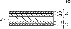
- FIG. 1 illustrates a schematic cross section of a basic structure of an all solid battery
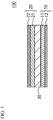
- FIG. 2 illustrates a schematic cross section of another all solid battery
- FIG. 3 illustrates a cross section of a first electrode layer and a second electrode layer
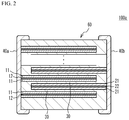
- FIG. 4 illustrates a flowchart of a manufacturing method of an all solid battery
- FIG. 5 illustrates a stacking process
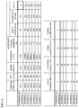
- FIG. 6 illustrates results of examples 1 to 6 and comparative examples 1 and 3.
- FIG. 1 illustrates a schematic cross section of a basic structure of an all solid battery 100 in accordance with an embodiment.
- the all solid battery 100 has a structure in which a first electrode 10 and a second electrode 20 sandwich an oxide-based solid electrolyte layer 30 .
- the first electrode 10 is provided on a first main face of the solid electrolyte layer 30 .
- the first electrode 10 has a structure in which a first electrode layer 11 and a first electric collector layer 12 are stacked.
- the first electrode layer 11 is on the solid electrolyte layer 30 side.
- the second electrode 20 is provided on a second main face of the solid electrolyte layer 30 .
- the second electrode 20 has a structure in which a second electrode layer 21 and a second electric collector layer 22 are stacked.
- the second electrode layer 21 is on the solid electrolyte layer 30 side.
- the all solid battery 100 is used as a secondary battery
- one of the first electrode 10 and the second electrode 20 is used as a positive electrode and the other is used as a negative electrode.
- the first electrode 10 is used as a positive electrode
- the second electrode 20 is used as a negative electrode.
- the solid electrolyte layer 30 is an oxide-based solid electrolyte.
- phosphoric acid salt-based electrolyte having a NASICON structure may be used for the solid electrolyte layer 30 .
- the phosphoric acid salt-based solid electrolyte having the NASICON structure has a high conductivity and is stable in normal atmosphere.
- the phosphoric acid salt-based solid electrolyte is, for example, such as a salt of phosphoric acid including lithium.
- the phosphoric acid salt is not limited.
- the phosphoric acid salt is such as composite salt of phosphoric acid with Ti (for example LiTi 2 (PO 4 ) 3 ).
- the phosphoric acid salt including lithium and having the NASICON structure is Li 1+x Al x Ge 2 ⁇ x (PO 4 ) 3 , Li 1 ⁇ x Al x Zr 2 ⁇ x (PO 4 ) 3 , Li 1+x Al x T 2 ⁇ x (PO 4 ) 3 or the like.
- Li—Al—Ge—PO 4 -based material to which a transition metal included in the phosphoric acid salt having the olivine type crystal structure included in the first electrode layer 11 and the second electrode layer 21 is added in advance, is used.
- the first electrode layer 11 and the second electrode layer 21 include phosphoric acid salt including Co and Li
- the solid electrolyte layer 30 includes Li—Al—Ge—PO 4 -based material to which Co is added in advance. In this case, it is possible to suppress solving of the transition metal included in the electrode active material into the electrolyte.
- the solid electrolyte layer 30 includes Li—Al—Ge—PO 4 -based material in which the transition metal is added in advance.
- the first electrode layer 11 used as a positive electrode includes a material having an olivine type crystal structure, as an electrode active material. It is preferable that the second electrode layer 21 also includes the electrode active material.
- the electrode active material is such as phosphoric acid salt including a transition metal and lithium.
- the olivine type crystal structure is a crystal of natural olivine. It is possible to identify the olivine type crystal structure, by using X-ray diffraction.
- LiCoPO 4 including Co may be used as a typical example of the electrode active material having the olivine type crystal structure.
- Other salts of phosphoric acid, in which Co acting as a transition metal is replaced to another transition metal in the above-mentioned chemical formula, may be used.
- a ratio of Li or PO 4 may fluctuate in accordance with a valence. It is preferable that Co, Mn, Fe, Ni or the like is used as the transition metal.
- the electrode active material having the olivine type crystal structure acts as a positive electrode active material in the first electrode layer 11 acting as a positive electrode.
- the electrode active material acts as the positive electrode active material.
- the second electrode layer 21 also includes an electrode active material having the olivine type crystal structure, discharge capacity may increase and an operation voltage may increase because of electric discharge, in the second electrode layer 21 acting as a negative electrode.
- the function mechanism is not completely clear. However, the mechanism may be caused by partial solid-phase formation together with the negative electrode active material.
- both the first electrode layer 11 and the second electrode layer 21 include an electrode active material having the olivine type crystal structure
- the electrode active material of each of the first electrode layer 11 and the second electrode layer 21 may have a common transition metal.
- the a transition metal of the electrode active material of the first electrode layer 11 may be different from that of the second electrode layer 21 .
- the first electrode layer 11 and the second electrode layer 21 may have only single type of transition metal.
- the first electrode layer 11 and the second electrode layer 21 may have two or more types of transition metal. It is preferable that the first electrode layer 11 and the second electrode layer 21 have a common transition metal. It is more preferable that the electrode active materials of the both electrode layers have the same chemical composition.
- the all solid battery 100 can be actually used without malfunction, in accordance with the usage purpose.
- the second electrode layer 21 may include known material as the negative electrode active material. When only one of the electrode layers includes the negative electrode active material, it is clarified that the one of the electrode layers acts as a negative electrode and the other acts as a positive electrode. When only one of the electrode layers includes the negative electrode active material, it is preferable that the one of the electrode layers is the second electrode layer 21 . Both of the electrode layers may include the known material as the negative electrode active material. Conventional technology of secondary batteries may be applied to the negative electrode active material. For example, titanium oxide, lithium-titanium complex oxide, lithium-titanium complex salt of phosphoric acid salt, a carbon, a vanadium lithium phosphate.
- oxide-based solid electrolyte material or a conductive material may be added.
- a conductive material conductive auxiliary agent
- the electrode layer paste includes a carbon material as the conductive auxiliary agent.
- the electrode may include a metal as the conductive auxiliary agent. Pd, Ni, Cu, or Fe, or an alloy thereof may be used as a metal of the conductive auxiliary agent.
- the first electric collector layer 12 and the second electric collector layer 22 are made of a conductive material.
- FIG. 2 illustrates a schematic cross section of an all solid battery 100 a in which a plurality of cell units are stacked.
- the all solid battery 100 a has a multilayer chip 60 having a rectangular parallelepiped shape, a first external electrode 40 a provided on a first edge face of the multilayer chip 60 , and a second external electrode 40 b provided on a second edge face facing with the first edge face.
- first external electrodes 40 a and the second external electrode 40 b extend to the upper face, the lower face and the two side faces of the multilayer chip 60 . However, the first external electrode 40 a and the second external electrode 40 b are spaced from each other.
- each of the first electric collector layers 12 and each of the second electric collector layers 22 are alternately stacked. Edges of the first electric collector layers 12 are exposed to the first edge face of the multilayer chip 60 but are not exposed to the second edge face of the multilayer chip 60 . Edges of the second electric collector layers 22 are exposed to the second edge face of the multilayer chip 60 but are not exposed to the first edge face. Thus, each of the first electric collector layers 12 and each of the second electric collector layers 22 are alternately conducted to the first external electrode 40 a and the second external electrode 40 b.
- the first electrode layer 11 is stacked on the first electric collector layer 12 .
- the solid electrolyte layer 30 is stacked on the first electrode layer 11 .
- the solid electrolyte layer 30 extends from the first external electrode 40 a to the second external electrode 40 b.
- the second electrode layer 21 is stacked on the solid electrolyte layer 30 .
- the second electric collector layer 22 is stacked on the second electrode layer 21 .
- Another second electrode layer 21 is stacked on the second electric collector layer 22 .
- Another solid electrolyte layer 30 is stacked on the second electrode layer 21 .
- the solid electrolyte layer 30 extends from the first external electrode 40 a to the second external electrode 40 b.
- the first electrode layer 11 is stacked on the solid electrolyte layer 30 .
- the stack units are repeatedly stacked. Therefore, the all solid battery 100 a has a structure in which a plurality of cell units are stacked.
- Pd is used as a conductive auxiliary agent of the first electrode layer 11 and the second electrode layer 21 , with use of characteristic in which Pd hardly reacts each material.
- a ratio of Pd in the first electrode layer 11 and the second electrode layer 21 is 20 vol. % to 50 vol. %, from a viewpoint of achieving conductive network in the electrode layers by spheroidizing of Pd and grain growing of Pd in the firing process.
- Pd prevents increasing of the amount of added active material in the electrode layers, when the volume fractional ratio of Pd is increased. Clarke number of Pd is extremely small. Therefore, Pd is very expensive.
- a carbon material is used as the conductive auxiliary agent of the first electrode layer 11 and the second electrode layer 21 .
- carbon is not spheroidized during a firing. And, grains of carbon does not grow during the firing. Therefore, carbon hardly prevents increasing of the amount of the added active material in the electrode layers, because carbons achieves high conductivity with a less volume fractional ratio. Moreover, carbon is not expensive.
- the carbon material tends to adsorb the liquid phase of the glass component during liquid-phase sintering of the solid electrolyte layer 30 .
- dense degree of the solid electrolyte layer 30 is reduced because of prevention of sintering of the solid electrolyte layer 30 or composition gap of the solid electrolyte layer 30 .
- ionic conductivity of the solid electrolyte layer 30 may be degraded. That is, when the carbon material is added to the first electrode layer 11 and the second electrode layer 21 , the reaction between the carbon material and the oxide-based solid electrolyte may be a problem.
- the structure of the conductive assistant may be broken down. And, an amount of conductive network formed by the conductive assistant may be reduced. In this case, the electron conductivity of the first electrode layer 11 and the second electrode layer 21 may be regraded.
- location changing of the carbon material caused by sintering of ceramic may be changed.
- At least one of the first electrode layer 11 and the second electrode layer 21 includes an aggregate of carbon particles.
- both the first electrode layer 11 and the second electrode layer 21 include the aggregate of carbon particles.
- FIG. 3 illustrates a schematic cross sectional view of the first electrode layer 11 and the second electrode layer 21 .
- the first electrode layer 11 and the second electrode layer 21 have a polycrystalline structure including a plurality of ceramic crystal grains 61 such as an electrode active material and an oxide-based solid electrolyte material.
- An aggregate 63 of carbon particles 62 is located at crystal grain boundary among the plurality of ceramic crystal grains 61 .
- the aggregate 63 houses a cavity 64 . That is, the aggregate 63 is aggregated so as to surround the cavity 64 .
- the aggregates 63 are scattered and located at a plurality of positions in the first electrode layer 11 and the second electrode layer 21 .
- the aggregate 63 may not necessarily surround the cavity 64 .
- the aggregate 63 may contact a part of the cavity 64 , and may demarcate a part of the cavity 64 .
- the cavity 64 may be surrounded by the aggregate 63 and the ceramic crystal grains 61 .
- the carbon particles 62 form the aggregate 63 . Therefore, dispersion of the carbon particles 62 is suppressed. In this case, an existence ratio of the carbon material is reduced at an interface between the first electrode layer 11 and the second electrode layer 21 , and the solid electrolyte layer 30 . Reaction between the carbon particles 62 and the oxide-based solid electrolyte is suppressed. Therefore, sintering prevention or composition shift of the solid electrolyte layer 30 is suppressed, and density degree of the solid electrolyte layer 30 is improved. And ionic conductivity is improved.
- the cavity 64 is demarcated by the aggregate 63 more flexible than the ceramic crystal grains 61 . And the cavity 64 does not include ceramic. With the structure, the volume changing of the active material during discharge and charge is absorbed by the cavity 64 . And inner stress is released. Therefore, the long-term cycle stability of the all solid battery 100 and the all solid battery 100 a is improved.
- an aggregation diameter of the aggregate 63 When an aggregation diameter of the aggregate 63 is small, it may not be necessarily absorb the volume changing. And so, it is preferable that the aggregation diameter of the aggregate 63 has a lower limit. In concrete, it is preferable that the aggregation diameter of the aggregate 63 is 0.5 ⁇ m or more. It is more preferable that the aggregation diameter is 1 ⁇ m or more. It is still more preferable that the aggregation diameter is 2 ⁇ m or more.
- the aggregation diameter of the aggregate 63 When the aggregation diameter of the aggregate 63 is large, the conductive network may be broken and the electron conductivity may be insufficient. And so, it is preferable that the aggregation diameter of the aggregate 63 has an upper limit. In concrete, it is preferable that the aggregation diameter of the aggregate 63 is 50 ⁇ m or less. It is more preferable that the aggregation diameter is 20 ⁇ m or less. It is still more preferable that the aggregation diameter is 10 ⁇ m or less.
- an average diameter of the cavities 64 is 0.2 ⁇ m or more. It is more preferable that the average diameter is 0.7 ⁇ m or more. It is still more preferable that the average diameter is 1 ⁇ m or more.
- BSE SEM
- the diameter of the cavity 64 in the aggregate 63 When the diameter of the cavity 64 in the aggregate 63 is large, water may enter the cavity portion and resistance to humidity may be degraded. And so, it is preferable that the diameter of the cavity 64 has an upper limit. In concrete, it is preferable that the diameter of the cavity 64 is 10 ⁇ m or less. It is more preferable that the diameter is 5 ⁇ m or less. It is still more preferable that the diameter is 2 ⁇ m or less.
- the area ratio of the cavity 64 in the aggregate 63 When an area ratio of the cavity 64 in the aggregate 63 is small, following against the volume changing of the discharge and charge may not be necessarily achieved and the cycle characteristic may be degraded. And so, it is preferable that the area ratio of the cavity 64 in the aggregate 63 has a lower limit. In concrete, it is preferable that the area ratio of the cavity 64 is 10% or more. It is more preferable that the area ratio of the cavity 64 is 20% or more. It is still more preferable that the area ratio of the cavity 64 is 25% or more.
- the area ratio of the cavity 64 in the aggregate 63 When the area ratio of the cavity 64 in the aggregate 63 is large, adhesion between the active material or the solid electrolyte and the carbon may be degraded and inner resistance may increase. And so, it is preferable that the area ratio of the cavity 64 in the aggregate 63 has an upper limit. In concrete, it is preferable that the area ratio of the cavity 64 is 80% or less. It is more preferable that the area ratio of the cavity 64 is 70% or less. It is still more preferable that the area ratio of the cavity 64 is 50% or less.
- an added amount of the carbon particles 62 has a lower limit.
- the added amount of the carbon particles 62 is 5 wt % or more with respect to the total amount of the active material and the solid electrolyte. It is more preferable that the added amount of the carbon particles 62 is 8 wt % or more. It is still more preferable that the added amount of the carbon particles 62 is 10 wt % or more.
- the added amount of the carbon particles 62 has an upper limit. In concrete, it is preferable that the added amount of the carbon particles 62 is 80 wt % or less with respect to the total amount of the active material and the solid electrolyte. It is more preferable that the added amount of the carbon particles 62 is 50 wt % or less. It is still more preferable that the added amount of the carbon particles 62 is 40 wt % or less.
- a primary particle average diameter of the carbon particles 62 has a lower limit and a BET value of the carbon particles 62 has an upper limit.
- the carbon particles 62 have the primary particle diameter of 15 nm or more and the BET value of 200 m 2 /g or less. It is more preferable that the carbon particles 62 have the primary particle diameter of 20 nm or more and the BET value of 150 m 2 /g or less. It is still more preferable that the carbon particles 62 have the primary particle diameter of 20 nm or more and the BET value of 80 m 2 /g or less.
- the primary particle average diameter of the carbon particles 62 has an upper limit and the BET value of the carbon particles 62 has a lower limit.
- the carbon particles 62 have the primary particle average diameter of 90 nm or less and the BET value of 8 m 2 /g or more. It is more preferable that the carbon particles 62 have the primary particle average diameter of 90 nm or less and the BET value of 10 m 2 /g or more. It is still more preferable that the carbon particles 62 have the primary particle average diameter of 80 nm or less and the BET value of 10 m 2 /g or more.
- the total area ratio of the aggregates 63 in whole of the first electrode layer 11 and the second electrode layer 21 is small, following against the volume changing caused by discharge and charge may not be necessarily achieved. And so, it is preferable that the total area ratio has a lower limit. In concrete, it is preferable that the total area ratio of the aggregates 63 in the whole of the first electrode layer 11 and the second electrode layer 21 is 15% or more. It is more preferable that the total area ratio is 20% or more. It is still more preferable that the total area ratio is 25% or more.
- the total area ratio of the aggregates 63 in the whole of the first electrode layer 11 and the second electrode layer 21 is large, capacity reduction or the like may occur. And so, it is preferable that the total area ratio has an upper limit. In concrete, it is preferable that the total area ratio of the aggregates 63 in the whole of the first electrode layer 11 and the second electrode layer 21 is 60% or less. It is more preferable that the total area ratio is 50% or less. It is still more preferable that the total area ratio is 40% or less.
- FIG. 4 illustrates a flowchart of the manufacturing method of the all solid battery 100 a.
- Phosphoric acid salt-based solid electrolyte powder for the solid electrolyte layer 30 is made.
- the phosphoric acid-based solid electrolyte powder by mixing raw material and additives and using solid phase synthesis method or the like.
- the resulting powder is subjected to dry grinding.
- a grain diameter of the resulting power is adjusted to a desired one.
- it is possible to adjust the grain diameter to the desired diameter with use of planetary ball mill using ZrO 2 ball of 5 mm ⁇ .
- the additive includes sintering assistant.
- the sintering assistant includes one or more of glass components such as Li—B—O-based compound, Li—Si—O-based compound, Li—C—O-based compound, Li—S—O-based compound and Li—P—O-based compound.
- the resulting powder is evenly dispersed into aqueous solvent or organic solvent together with a binding agent, a dispersing agent, a plasticizer and so on.
- the resulting power is subjected wet crushing.
- solid electrolyte slurry having a desired particle diameter is obtained.
- a bead mill, a wet jet mill, a kneader, a high pressure homogenizer or the like may be used. It is preferable that the bead mill is used because adjusting of particle size distribution and dispersion are performed at the same time.
- a binder is added to the resulting solid electrolyte slurry.
- solid electrolyte paste is obtained.
- the solid electrolyte paste is painted.
- the painting method is not limited.
- a slot die method, a reverse coat method, a gravure coat method, a bar coat method, a doctor blade method or the like may be used. It is possible to measure the particle size distribution after the wet-crushing, by using a laser diffraction measurement device using a laser diffraction scattering method.
- paste for electrode layer is made in order to make the first electrode layer 11 and the second electrode layer 21 .
- an active material and solid electrolyte material are evenly dispersed by using a bead mill or the like.
- ceramic paste which includes only ceramic particles is made.
- the ceramic paste and the carbon paste are mixed with each other.
- the carbon particles 62 are, for example, carbon black or the like.
- the aggregation diameter of the aggregate 63 becomes larger. It is possible to adjust the aggregation diameter of the aggregate 63 of the carbon particles 62 by adjusting the loosening level, in this manner.
- paste for electric collector is made in order to make the first electric collector layer 12 and the second electric collector layer 22 . It is possible to make the paste for electric collector, by evenly dispersing powder of Pd, a binder, dispersant, plasticizer and so on into water or organic solvent.
- the paste for electrode layer and the paste for electric collector are printed on both faces of the green sheet, with respect to the all solid battery 100 illustrated in FIG. 1 .
- the printing method is not limited.
- a screen printing method, an intaglio printing method, a letter press printing method, a calendar roll printing method or the like may be used.
- the screen printing is generally used.
- an ink jet printing may be preferable when a micro size electrode pattern or a special shape is necessary.
- Paste 52 for electrode layer is printed on one face of a green sheet 51 as illustrated in FIG. 4 , with respect to the all solid battery 100 illustrated in FIG. 2 .
- Paste 53 for electric collector is printed on the paste 52 for electrode layer.
- another paste 52 for electrode layer is printed on the paste 53 for electric collector.
- a reverse pattern 54 is printed on a part of the green sheet 51 where neither the paste 52 for electrode layer nor the paste 53 for electric collector is printed.
- a material of the reverse pattern 54 may be the same as that of the green sheet 51 .
- the green sheets 51 after printing are stacked so that each of the green sheets 51 is alternately shifted to each other.
- a multilayer structure is obtained. In this case, in the multilayer structure, a pair of the paste 52 for electrode layer and the paste 53 for electric collector are alternately exposed to the two edge faces of the multilayer structure.
- the obtained multilayer structure is fired.
- an upper limit is determined in the oxygen partial pressure in the firing atmosphere, from a viewpoint of suppression of loss of the carbon material included in the paste of electrode layer.
- the oxygen partial pressure in the firing atmosphere is 2 ⁇ 10 ⁇ 13 atm or less.
- a lower limit is determined in the oxygen partial pressure in the firing atmosphere, from a viewpoint of suppression of the melting of the phosphoric acid salt-based solid electrolyte.
- the oxygen partial pressure in the firing atmosphere is 5 ⁇ 10 ⁇ 22 atm or more.
- the multilayer chip 60 may be put in a dedicated tool so that the first external electrode 40 a is spaced from the second external electrode 40 b on the upper face, the lower face and the two side faces connected to the two end faces.
- electrodes may be formed by a sputtering.
- the first external electrode 40 a and the second external electrode 40 b may be formed by plating on the formed electrodes.
- the paste for electrode layer including the aggregate 63 of the carbon particles 62 is used. Therefore, as illustrated in FIG. 3 , the aggregate 63 of the carbon particles 62 is located at crystal grain boundary between a plurality of the ceramic crystal grains 61 .
- the cavity 64 of which at least a part is demarcated by the aggregate 63 is formed. Therefore, even if the carbon material is used, the ionic conductivity, the electron conductivity and the long-term cycle stability are improved. It is therefore possible to suppress the cost and improve the performance of the all solid battery 100 and the all solid battery 100 a.
- Example 1 Co 3 O 4 , Li 2 CO 3 , dihydrogen phosphate ammonium, Al 2 O 3 , GeO 2 were mixed and were used as solid electrolyte material powder. From the solid electrolyte material powder, Li 1.3 Al 0.3 Ge 1.7 (PO 4 ) 3 including a predetermined amount of Co was made by a solid phase synthesizing. The resulting power was dry-crushed by ZrO 2 balls of 5 mm ⁇ (30 min at a rotation speed of 400 rpm with use of planetary ball mil). The D90% grain diameter was 5 ⁇ m or less.
- the resulting powder was wet-crushed (dispersing medium: ion exchange water or ethanol) with beads of 1.5 mm ⁇ so that the D90% grain diameter was 3 ⁇ m. Further, the resulting powder was wet-crushed with beads of 1 mm ⁇ so that the D50% grain diameter was 0.3 ⁇ m.
- solid electrolyte slurry having the D90% grain diameter of 2 ⁇ m or less was made.
- Solid electrolyte paste was obtained by adding a binder to the resulting slurry. And, green sheet having a thickness of 10 ⁇ m was made.
- Li 1.3 Al 0.3 Ti 1.7 (PO 4 ) 3 including a predetermined amount of LiCoPO 4 was synthesized by a solid phase synthesizing as well as the above-mentioned oxide.
- the resulting electrode active material and the solid electrolyte material were highly dispersed with use of wet-bead mill. Thus, ceramic paste including only ceramic grains was made.
- carbon paste in which carbon black was not highly dispersed was made.
- the ceramic paste and the carbon paste were sufficiently mixed.
- paste for internal electrode layer was made.
- a primary particle average diameter of the carbon black was 20 nm.
- a BET value of the carbon black was 80 m 2 /g.
- An added amount of the carbon black was 5 wt % with respect to the glass ceramic component.
- An average aggregation diameter of the aggregate of the carbon black was 0.7
- the average aggregation diameter of the aggregate was adjusted by loosening level of the carbon black. In the example 1, the loosening level was “large”.
- the primary particle average diameter was calculated by taking some SEM images of only the carbon black so that the number of the carbon black was 100 or so in a single image and the total number of the carbon black was 400 or more and measuring a tangential diameter in a constant direction of 300 numbers or more of the carbon black and calculating an average of the tangential diameters.
- the BET value of the carbon black was measured by a BET one point method by using Macsorb HM model-1200 series, nitrogen gas and nitrogen-helium (30 mol %) mixed gas.
- a sample amount of the carbon black was measured so that an actual measured value was 1 to 50 m 2 .
- the sample carbon black was housed in a glass cell. The sample carbon black was heated for 15 minutes at 200 degrees C., while nitrogen gas was flown in the glass cell.
- the carbon black paste of 0.001 g was dispersed in ethanol of 50 ml in an ultrasonic bath for 3 minutes. After that, the diameter of the aggregate was measured by using ELSZ-2000S made by Otsuka Electronics Co., Ltd. The measured diameter was treated as the aggregation diameter.
- the stacked green sheets were used as a solid electrolyte layer.
- the paste for electrode layer was stacked on both an upper face and a lower face of the solid electrolyte layer.
- the resulting structure was stamped into a rectangular board shape of ⁇ 10 mm.
- the board shape structure was used as a sample.
- the samples were fired.
- the firing temperature was 700 degrees C.
- the oxygen partial pressure during the firing process was 10 ⁇ 13 atm or less at a temperature of 500 degrees C. or less.
- Example 2 The loosening level of the carbon black was “middle”. The average aggregation diameter of the aggregate was 2.5 ⁇ m. Other conditions were the same as those of the example 1.
- Example 3 The added amount of the carbon black was 25 wt % with respect to the glass ceramic component. The loosening level of the carbon black was “middle”. The average aggregation diameter of the aggregate was 3.8 ⁇ m. Other conditions were the same as those of the example 1.
- Example 4 The added amount of the carbon black was 30 wt % with respect to the ceramic component. The loosening level of the carbon black was “middle”. The average aggregation diameter of the aggregate was 7.4 ⁇ m. Other conditions were the same as those of the example 1.
- Example 5 The loosening level of the carbon black was “small”. The average aggregation diameter of the aggregate was 8.9 ⁇ m. Other conditions were the same as those of the example 1.
- Example 6 The primary particle average diameter of the carbon black was 80 nm.
- the BET value of the carbon black was 10 m 2 /g.
- the loosening level of the carbon black was “small”.
- the average aggregation diameter of the aggregate was 9.5 ⁇ m.
- Other conditions were the same as those of the example 1.
- the area ratio of the cavity in the aggregate was 5% in the example 1.
- the area ratio of the example 2 was 26%.
- the area ratio of the example 3 was 26%.
- the area ratio of the example 4 was 24%.
- the area ratio of the example 5 was 50%.
- the area ratio of the example 6 was 30%.
- the area ratio of the comparative example 1 was 2%.
- the volume ratio of the aggregate with respect to the whole of the electrode layers was 7% in the example 1.
- the volume ratio was 10% in the example 2.
- the volume ratio was 43% in the example 3.
- the volume ratio was 50% in the example 4.
- the volume ratio was 15% in the example 5.
- the volume ratio was 9% in the example 6.
- the volume ratio was 5% in the comparative example 1.
- Cycle characteristic was measured with respect to the examples 1 to 6 and the comparative example 1.
- the cycle characteristic of the examples 1 and 4 was determined as good “ ⁇ ”.
- the cycle characteristic of the examples 2, 3, 5 and 6 was determined as very good “ ⁇ ”.
- the cycle characteristic of the comparative example 1 was determined as bad “X”.
- charge and discharge were performed at 25 degrees C., within a voltage range of 2.7 V to 0 V and with 1 C.
- the cycle characteristic was determined as very good “ ⁇ ”.
- the discharge capacity with respect to the initial discharge capacity after 100 cycles was 60% or more
- the cycle characteristic was determined as good “ ⁇ ”.
- the cycle characteristic was determined as bad “X”.
- the electron conductivity was measured with respect to the examples 1 to 6 and the comparative example 1.
- the electron conductivity of the examples 1 to 3 was determined as very good “ ⁇ ”.
- the electron conductivity of the examples 4 to 6 and the comparative example 1 was determined as good “ ⁇ ”.
- a pellet having a diameter of 10 mm ⁇ and a thickness of 2 mm was made from mixed powder in which the electrode paste was dried. And, a sintered structure was made with the same method as the all solid battery.
- a gold electrode was formed on an upper face and a lower face of the sintered structure by sputtering. And conductivity was measured. When the conductivity was 10 0 S/cm or more, the electron conductivity was determined as very good “ ⁇ ”. When the conductivity was 10 ⁇ 4 to 10 ⁇ 1 S/cm, the electron conductivity was determined as good “ ⁇ ”. When the conductivity was 10 ⁇ 4 S/cm or less, the electron conductivity was determined as bad “X”.
- the ionic conductivity was measured with respect to the examples 1 to 6 and the comparative example 1.
- the ionic conductivity of the examples 1 and 2 was determined as very good “ ⁇ ”.
- the ionic conductivity of the examples 3, 5 and 6 was determined as good “ ⁇ ”.
- the ionic conductivity of the example 4 was determined as so-so “ ⁇ ”.
- a pellet having a diameter of 10 mm ⁇ and a thickness of 2 mm was made from mixed powder in which the electrode paste was dried.
- a solid electrolyte layer having a thickness of 10 ⁇ m was formed on an upper face and a lower face of the pellet. And, a sintered structure was made with the same method as the all solid battery.
- a gold electrode was formed on an upper face and a lower face of the sintered structure by sputtering. And conductivity was measured. When the conductivity was 10 ⁇ 5 S/cm or more, the ionic conductivity was determined as very good “ ⁇ ”. When the conductivity was 10 ⁇ 6 to 10 ⁇ 6 S/cm, the ionic conductivity was determined as good “ ⁇ ”. When the conductivity was 10 ⁇ 6 S/cm or less, the ionic conductivity was determined as bad “x”.
- the cycle characteristic of the examples 2, 3, 5 and 6 was determined as very good “ ⁇ ”. It is thought that this was because the area ratio of the cavity in the aggregate was 25% or more.
- the ionic conductivity of the examples 1 and 2 was determined as very good “ ⁇ ”. It is thought that this was because the added amount of the carbon was small and the aggregation diameter was appropriate, the prevention of sintering was suppressed, the ceramic component was densified, and the ionic conductivity was improved.
Landscapes
- Chemical & Material Sciences (AREA)
- Chemical Kinetics & Catalysis (AREA)
- Electrochemistry (AREA)
- General Chemical & Material Sciences (AREA)
- Engineering & Computer Science (AREA)
- Manufacturing & Machinery (AREA)
- Physics & Mathematics (AREA)
- Condensed Matter Physics & Semiconductors (AREA)
- General Physics & Mathematics (AREA)
- Inorganic Chemistry (AREA)
- Secondary Cells (AREA)
- Battery Electrode And Active Subsutance (AREA)
Abstract
Description
- This application is based upon and claims the benefit of priority of the prior Japanese Patent Application No. 2019-115730, filed on Jun. 21, 2019, the entire contents of which are incorporated herein by reference.
- A certain aspect of the present invention relates to an all solid battery.
- Recently, secondary batteries are being used in various fields. Secondary batteries having electrolytic liquid have a problem such as leak of the electrolytic liquid. And so, all solid batteries having a solid electrolyte and other solid elements are being developed.
- It is thought that for the purpose of securing electron conductivity, Pd (palladium) is used as conductive auxiliary agent of electrode layers, with use of characteristic in which Pd hardly reacts each material. However, Pd in the electrode layers suppresses increasing of an amount of an added active material in the electrode layers. And so, it is preferable that carbon is used as the conductive auxiliary agent of the electrode layers (for example, see Japanese Patent Application Publication No. 2017-212123 hereinafter referred to as Document 1). However, when the carbon is used as the conductive auxiliary agent of the electrode layers, ionic conductivity may be degraded.
- However, when the carbon is added to the electrode layer, reaction between the carbon and oxide-based solid electrolyte during a firing process may degrade the ionic conductivity of solid electrolyte layers. When the carbon is excessively dispersed in the electrode layers, an amount of conductive network formed by the conductive assistant may be reduced. In this case, the electron conductivity of the electrode layers may be regraded. And, in an oxide-based all solid battery formed by sintering, volume expansion contraction of an active material caused by discharge and charge causes degradation of long-term cycle stability.
-
Document 1 disclose a method for suppressing the reaction by using alumina coating. However, cost may increase. Capacity density may be degraded. And, conductivity may be degraded. The problem of the volume expansion contraction may not be necessarily solved. - The present invention has a purpose of providing an all solid battery that is capable of suppressing cost and improving performance.
- According to an aspect of the present invention, there is provided an all solid battery including: a solid electrolyte layer of which a main component is oxide-based solid electrolyte; a first electrode layer that is provided on a first main face of the solid electrolyte layer and includes an active material; and a second electrode layer that is provided on a second main face of the solid electrolyte layer and includes an active material, wherein at least one of the first electrode layer and the second electrode layer includes an aggregate of carbon particles and a cavity, wherein the aggregate demarcates at least a part of the cavity.
-
FIG. 1 illustrates a schematic cross section of a basic structure of an all solid battery; -
FIG. 2 illustrates a schematic cross section of another all solid battery; -
FIG. 3 illustrates a cross section of a first electrode layer and a second electrode layer; -
FIG. 4 illustrates a flowchart of a manufacturing method of an all solid battery; -
FIG. 5 illustrates a stacking process; and -
FIG. 6 illustrates results of examples 1 to 6 and comparative examples 1 and 3. - A description will be given of an embodiment with reference to the accompanying drawings.
- (Embodiment)
FIG. 1 illustrates a schematic cross section of a basic structure of an allsolid battery 100 in accordance with an embodiment. As illustrated inFIG. 1 , the allsolid battery 100 has a structure in which afirst electrode 10 and asecond electrode 20 sandwich an oxide-basedsolid electrolyte layer 30. Thefirst electrode 10 is provided on a first main face of thesolid electrolyte layer 30. Thefirst electrode 10 has a structure in which afirst electrode layer 11 and a firstelectric collector layer 12 are stacked. Thefirst electrode layer 11 is on thesolid electrolyte layer 30 side. Thesecond electrode 20 is provided on a second main face of thesolid electrolyte layer 30. Thesecond electrode 20 has a structure in which asecond electrode layer 21 and a secondelectric collector layer 22 are stacked. Thesecond electrode layer 21 is on thesolid electrolyte layer 30 side. - When the all
solid battery 100 is used as a secondary battery, one of thefirst electrode 10 and thesecond electrode 20 is used as a positive electrode and the other is used as a negative electrode. In the embodiment, as an example, thefirst electrode 10 is used as a positive electrode, and thesecond electrode 20 is used as a negative electrode. - At least, the
solid electrolyte layer 30 is an oxide-based solid electrolyte. For example, phosphoric acid salt-based electrolyte having a NASICON structure may be used for thesolid electrolyte layer 30. The phosphoric acid salt-based solid electrolyte having the NASICON structure has a high conductivity and is stable in normal atmosphere. The phosphoric acid salt-based solid electrolyte is, for example, such as a salt of phosphoric acid including lithium. The phosphoric acid salt is not limited. For example, the phosphoric acid salt is such as composite salt of phosphoric acid with Ti (for example LiTi2(PO4)3). Alternatively, at least a part of Ti may be replaced with a transition metal of which a valence is four, such as Ge, Sn, Hf, or Zr. In order to increase an amount of Li, a part of Ti may be replaced with a transition metal of which a valence is three, such as Al, Ga, In, Y or La. In concrete, the phosphoric acid salt including lithium and having the NASICON structure is Li1+xAlxGe2−x(PO4)3, Li1−xAlxZr2−x(PO4)3, Li1+xAlxT2−x(PO4)3 or the like. For example, it is preferable that Li—Al—Ge—PO4-based material, to which a transition metal included in the phosphoric acid salt having the olivine type crystal structure included in thefirst electrode layer 11 and thesecond electrode layer 21 is added in advance, is used. For example, when thefirst electrode layer 11 and thesecond electrode layer 21 include phosphoric acid salt including Co and Li, it is preferable that thesolid electrolyte layer 30 includes Li—Al—Ge—PO4-based material to which Co is added in advance. In this case, it is possible to suppress solving of the transition metal included in the electrode active material into the electrolyte. When thefirst electrode layer 11 and thesecond electrode layer 21 include phosphoric acid salt including Li and a transition metal other than Co, it is preferable that thesolid electrolyte layer 30 includes Li—Al—Ge—PO4-based material in which the transition metal is added in advance. - At least, the
first electrode layer 11 used as a positive electrode includes a material having an olivine type crystal structure, as an electrode active material. It is preferable that thesecond electrode layer 21 also includes the electrode active material. The electrode active material is such as phosphoric acid salt including a transition metal and lithium. The olivine type crystal structure is a crystal of natural olivine. It is possible to identify the olivine type crystal structure, by using X-ray diffraction. - For example, LiCoPO4 including Co may be used as a typical example of the electrode active material having the olivine type crystal structure. Other salts of phosphoric acid, in which Co acting as a transition metal is replaced to another transition metal in the above-mentioned chemical formula, may be used. A ratio of Li or PO4 may fluctuate in accordance with a valence. It is preferable that Co, Mn, Fe, Ni or the like is used as the transition metal.
- The electrode active material having the olivine type crystal structure acts as a positive electrode active material in the
first electrode layer 11 acting as a positive electrode. For example, when only thefirst electrode layer 11 includes the electrode active material having the olivine type crystal structure, the electrode active material acts as the positive electrode active material. When thesecond electrode layer 21 also includes an electrode active material having the olivine type crystal structure, discharge capacity may increase and an operation voltage may increase because of electric discharge, in thesecond electrode layer 21 acting as a negative electrode. The function mechanism is not completely clear. However, the mechanism may be caused by partial solid-phase formation together with the negative electrode active material. - When both the
first electrode layer 11 and thesecond electrode layer 21 include an electrode active material having the olivine type crystal structure, the electrode active material of each of thefirst electrode layer 11 and thesecond electrode layer 21 may have a common transition metal. Alternatively, the a transition metal of the electrode active material of thefirst electrode layer 11 may be different from that of thesecond electrode layer 21. Thefirst electrode layer 11 and thesecond electrode layer 21 may have only single type of transition metal. Thefirst electrode layer 11 and thesecond electrode layer 21 may have two or more types of transition metal. It is preferable that thefirst electrode layer 11 and thesecond electrode layer 21 have a common transition metal. It is more preferable that the electrode active materials of the both electrode layers have the same chemical composition. When thefirst electrode layer 11 and thesecond electrode layer 21 have a common transition metal or a common electrode active material of the same composition, similarity between the compositions of the both electrode layers increases. Therefore, even if terminals of the allsolid battery 100 are connected in a positive/negative reversed state, the allsolid battery 100 can be actually used without malfunction, in accordance with the usage purpose. - The
second electrode layer 21 may include known material as the negative electrode active material. When only one of the electrode layers includes the negative electrode active material, it is clarified that the one of the electrode layers acts as a negative electrode and the other acts as a positive electrode. When only one of the electrode layers includes the negative electrode active material, it is preferable that the one of the electrode layers is thesecond electrode layer 21. Both of the electrode layers may include the known material as the negative electrode active material. Conventional technology of secondary batteries may be applied to the negative electrode active material. For example, titanium oxide, lithium-titanium complex oxide, lithium-titanium complex salt of phosphoric acid salt, a carbon, a vanadium lithium phosphate. - In the forming process of the
first electrode layer 11 and thesecond electrode layer 21, moreover, oxide-based solid electrolyte material or a conductive material (conductive auxiliary agent) may be added. When the material is evenly dispersed into water or organic solution together with binder or plasticizer, paste for electrode layer is obtained. In the embodiment, the electrode layer paste includes a carbon material as the conductive auxiliary agent. Moreover, the electrode may include a metal as the conductive auxiliary agent. Pd, Ni, Cu, or Fe, or an alloy thereof may be used as a metal of the conductive auxiliary agent. - The first
electric collector layer 12 and the secondelectric collector layer 22 are made of a conductive material. -
FIG. 2 illustrates a schematic cross section of an allsolid battery 100 a in which a plurality of cell units are stacked. The allsolid battery 100 a has amultilayer chip 60 having a rectangular parallelepiped shape, a firstexternal electrode 40 a provided on a first edge face of themultilayer chip 60, and a secondexternal electrode 40 b provided on a second edge face facing with the first edge face. - In four faces other than the two end faces of the
multilayer chip 60, two faces other than an upper face and a lower face of themultilayer chip 60 in a stacking direction are referred to as side faces. The firstexternal electrodes 40 a and the secondexternal electrode 40 b extend to the upper face, the lower face and the two side faces of themultilayer chip 60. However, the firstexternal electrode 40 a and the secondexternal electrode 40 b are spaced from each other. - In the following description, the same numeral is added to each member that has the same composition range, the same thickness range and the same particle distribution range as that of the all
solid battery 100. And, a detail explanation of the same member is omitted. - In the all
solid battery 100 a, each of the first electric collector layers 12 and each of the second electric collector layers 22 are alternately stacked. Edges of the first electric collector layers 12 are exposed to the first edge face of themultilayer chip 60 but are not exposed to the second edge face of themultilayer chip 60. Edges of the second electric collector layers 22 are exposed to the second edge face of themultilayer chip 60 but are not exposed to the first edge face. Thus, each of the first electric collector layers 12 and each of the second electric collector layers 22 are alternately conducted to the firstexternal electrode 40 a and the secondexternal electrode 40 b. - The
first electrode layer 11 is stacked on the firstelectric collector layer 12. Thesolid electrolyte layer 30 is stacked on thefirst electrode layer 11. Thesolid electrolyte layer 30 extends from the firstexternal electrode 40 a to the secondexternal electrode 40 b. Thesecond electrode layer 21 is stacked on thesolid electrolyte layer 30. The secondelectric collector layer 22 is stacked on thesecond electrode layer 21. Anothersecond electrode layer 21 is stacked on the secondelectric collector layer 22. Anothersolid electrolyte layer 30 is stacked on thesecond electrode layer 21. Thesolid electrolyte layer 30 extends from the firstexternal electrode 40 a to the secondexternal electrode 40 b. Thefirst electrode layer 11 is stacked on thesolid electrolyte layer 30. In the allsolid battery 100 a, the stack units are repeatedly stacked. Therefore, the allsolid battery 100 a has a structure in which a plurality of cell units are stacked. - It is thought that Pd is used as a conductive auxiliary agent of the
first electrode layer 11 and thesecond electrode layer 21, with use of characteristic in which Pd hardly reacts each material. However, it is preferable that a ratio of Pd in thefirst electrode layer 11 and thesecond electrode layer 21 is 20 vol. % to 50 vol. %, from a viewpoint of achieving conductive network in the electrode layers by spheroidizing of Pd and grain growing of Pd in the firing process. And, Pd prevents increasing of the amount of added active material in the electrode layers, when the volume fractional ratio of Pd is increased. Clarke number of Pd is extremely small. Therefore, Pd is very expensive. And so, it is preferable that a carbon material is used as the conductive auxiliary agent of thefirst electrode layer 11 and thesecond electrode layer 21. On the other hand, carbon is not spheroidized during a firing. And, grains of carbon does not grow during the firing. Therefore, carbon hardly prevents increasing of the amount of the added active material in the electrode layers, because carbons achieves high conductivity with a less volume fractional ratio. Moreover, carbon is not expensive. - However, the carbon material tends to adsorb the liquid phase of the glass component during liquid-phase sintering of the
solid electrolyte layer 30. When the carbon material adsorbs the liquid phase of the glass component, dense degree of thesolid electrolyte layer 30 is reduced because of prevention of sintering of thesolid electrolyte layer 30 or composition gap of thesolid electrolyte layer 30. And, ionic conductivity of thesolid electrolyte layer 30 may be degraded. That is, when the carbon material is added to thefirst electrode layer 11 and thesecond electrode layer 21, the reaction between the carbon material and the oxide-based solid electrolyte may be a problem. - Next, when the carbon is excessively dispersed in the
first electrode layer 11 and thesecond electrode layer 21, the structure of the conductive assistant may be broken down. And, an amount of conductive network formed by the conductive assistant may be reduced. In this case, the electron conductivity of thefirst electrode layer 11 and thesecond electrode layer 21 may be regraded. When the carbon material is excessively dispersed, location changing of the carbon material caused by sintering of ceramic may be changed. - Next, in an oxide-based all solid battery formed by sintering, volume expansion contraction of an active material caused by discharge and charge causes stress. Thereby, long-term cycle stability may be degraded.
- And so, in the embodiment, at least one of the
first electrode layer 11 and thesecond electrode layer 21 includes an aggregate of carbon particles. In the embodiment, as an example, both thefirst electrode layer 11 and thesecond electrode layer 21 include the aggregate of carbon particles. -
FIG. 3 illustrates a schematic cross sectional view of thefirst electrode layer 11 and thesecond electrode layer 21. As illustrated inFIG. 3 , thefirst electrode layer 11 and thesecond electrode layer 21 have a polycrystalline structure including a plurality ofceramic crystal grains 61 such as an electrode active material and an oxide-based solid electrolyte material. Anaggregate 63 ofcarbon particles 62 is located at crystal grain boundary among the plurality ofceramic crystal grains 61. The aggregate 63 houses acavity 64. That is, the aggregate 63 is aggregated so as to surround thecavity 64. Theaggregates 63 are scattered and located at a plurality of positions in thefirst electrode layer 11 and thesecond electrode layer 21. - The aggregate 63 may not necessarily surround the
cavity 64. For example, the aggregate 63 may contact a part of thecavity 64, and may demarcate a part of thecavity 64. In this case, thecavity 64 may be surrounded by the aggregate 63 and theceramic crystal grains 61. - The
carbon particles 62 form theaggregate 63. Therefore, dispersion of thecarbon particles 62 is suppressed. In this case, an existence ratio of the carbon material is reduced at an interface between thefirst electrode layer 11 and thesecond electrode layer 21, and thesolid electrolyte layer 30. Reaction between thecarbon particles 62 and the oxide-based solid electrolyte is suppressed. Therefore, sintering prevention or composition shift of thesolid electrolyte layer 30 is suppressed, and density degree of thesolid electrolyte layer 30 is improved. And ionic conductivity is improved. - Next, when the dispersion of the
carbon particles 62 is suppressed, breakdown of the structure of the conductive assistant is suppressed. And, reduction of an amount of conductive network formed by the conductive assistant is suppressed. Thus, electron conductivity of thefirst electrode layer 11 and thesecond electrode layer 21 is improved. When the dispersion of thecarbon particles 62 is suppressed, location changing of thecarbon particles 62 caused by sintering of ceramic is suppressed. - The
cavity 64 is demarcated by the aggregate 63 more flexible than theceramic crystal grains 61. And thecavity 64 does not include ceramic. With the structure, the volume changing of the active material during discharge and charge is absorbed by thecavity 64. And inner stress is released. Therefore, the long-term cycle stability of the allsolid battery 100 and the allsolid battery 100 a is improved. - Accordingly, even if the carbon material is used, the ionic conductivity, the electron conductivity and the long-term cycle stability are improved. It is therefore possible to reduce cost and improve performance of the all
solid battery 100 and the allsolid battery 100 a. - When an aggregation diameter of the aggregate 63 is small, it may not be necessarily absorb the volume changing. And so, it is preferable that the aggregation diameter of the aggregate 63 has a lower limit. In concrete, it is preferable that the aggregation diameter of the aggregate 63 is 0.5 μm or more. It is more preferable that the aggregation diameter is 1 μm or more. It is still more preferable that the aggregation diameter is 2 μm or more.
- When the aggregation diameter of the aggregate 63 is large, the conductive network may be broken and the electron conductivity may be insufficient. And so, it is preferable that the aggregation diameter of the aggregate 63 has an upper limit. In concrete, it is preferable that the aggregation diameter of the aggregate 63 is 50 μm or less. It is more preferable that the aggregation diameter is 20 μm or less. It is still more preferable that the aggregation diameter is 10 μm or less.
- When a diameter of the
cavity 64 in the aggregate 63 is small, absorption of the volume changing of the active material may be insufficient. And so, it is preferable that the diameter of thecavity 64 has a lower limit. In concrete, it is preferable that an average diameter of thecavities 64 is 0.2 μm or more. It is more preferable that the average diameter is 0.7 μm or more. It is still more preferable that the average diameter is 1 μm or more. It is possible to calculate the average diameter of thecavities 64 by taking some SEM (BSE) images of a cross section of the all solid battery subjected to CP process so that the number of thecavity 64 is 50 in a single image and the total number of thecavity 64 is 300 or more and measuring a tangential diameter in a constant direction of thecavities 64 and calculating an average of the tangential diameters. - When the diameter of the
cavity 64 in the aggregate 63 is large, water may enter the cavity portion and resistance to humidity may be degraded. And so, it is preferable that the diameter of thecavity 64 has an upper limit. In concrete, it is preferable that the diameter of thecavity 64 is 10 μm or less. It is more preferable that the diameter is 5 μm or less. It is still more preferable that the diameter is 2 μm or less. - When an area ratio of the
cavity 64 in the aggregate 63 is small, following against the volume changing of the discharge and charge may not be necessarily achieved and the cycle characteristic may be degraded. And so, it is preferable that the area ratio of thecavity 64 in the aggregate 63 has a lower limit. In concrete, it is preferable that the area ratio of thecavity 64 is 10% or more. It is more preferable that the area ratio of thecavity 64 is 20% or more. It is still more preferable that the area ratio of thecavity 64 is 25% or more. - When the area ratio of the
cavity 64 in the aggregate 63 is large, adhesion between the active material or the solid electrolyte and the carbon may be degraded and inner resistance may increase. And so, it is preferable that the area ratio of thecavity 64 in the aggregate 63 has an upper limit. In concrete, it is preferable that the area ratio of thecavity 64 is 80% or less. It is more preferable that the area ratio of thecavity 64 is 70% or less. It is still more preferable that the area ratio of thecavity 64 is 50% or less. - When an amount of the
carbon particles 62 added to thefirst electrode layer 11 and thesecond electrode layer 21 is small, conductivity of thefirst electrode layer 11 and thesecond electrode layer 21 may be degraded. And so, it is preferable that an added amount of thecarbon particles 62 has a lower limit. In concrete, it is preferable that the added amount of thecarbon particles 62 is 5 wt % or more with respect to the total amount of the active material and the solid electrolyte. It is more preferable that the added amount of thecarbon particles 62 is 8 wt % or more. It is still more preferable that the added amount of thecarbon particles 62 is 10 wt % or more. - When the amount of the
carbon particles 62 added to thefirst electrode layer 11 and thesecond electrode layer 21 is large, prevention of sintering of thefirst electrode layer 11 and thesecond electrode layer 21 may be remarkable. And so, it is preferable that the added amount of thecarbon particles 62 has an upper limit. In concrete, it is preferable that the added amount of thecarbon particles 62 is 80 wt % or less with respect to the total amount of the active material and the solid electrolyte. It is more preferable that the added amount of thecarbon particles 62 is 50 wt % or less. It is still more preferable that the added amount of thecarbon particles 62 is 40 wt % or less. - When the
carbon particles 62 is small, dispersion of thecarbon particles 62 in thefirst electrode layer 11 and thesecond electrode layer 21 may not be necessarily suppressed. And so, it is preferable that a primary particle average diameter of thecarbon particles 62 has a lower limit and a BET value of thecarbon particles 62 has an upper limit. In concrete, it is preferable that thecarbon particles 62 have the primary particle diameter of 15 nm or more and the BET value of 200 m2/g or less. It is more preferable that thecarbon particles 62 have the primary particle diameter of 20 nm or more and the BET value of 150 m2/g or less. It is still more preferable that thecarbon particles 62 have the primary particle diameter of 20 nm or more and the BET value of 80 m2/g or less. - When the
carbon particles 62 are large, the conductivity of thefirst electrode layer 11 and thesecond electrode layer 21 may be degraded. And so, it is preferable that the primary particle average diameter of thecarbon particles 62 has an upper limit and the BET value of thecarbon particles 62 has a lower limit. In concrete, it is preferable that thecarbon particles 62 have the primary particle average diameter of 90 nm or less and the BET value of 8 m2/g or more. It is more preferable that thecarbon particles 62 have the primary particle average diameter of 90 nm or less and the BET value of 10 m2/g or more. It is still more preferable that thecarbon particles 62 have the primary particle average diameter of 80 nm or less and the BET value of 10 m2/g or more. - When a total area ratio of the
aggregates 63 in whole of thefirst electrode layer 11 and thesecond electrode layer 21 is small, following against the volume changing caused by discharge and charge may not be necessarily achieved. And so, it is preferable that the total area ratio has a lower limit. In concrete, it is preferable that the total area ratio of theaggregates 63 in the whole of thefirst electrode layer 11 and thesecond electrode layer 21 is 15% or more. It is more preferable that the total area ratio is 20% or more. It is still more preferable that the total area ratio is 25% or more. - When the total area ratio of the
aggregates 63 in the whole of thefirst electrode layer 11 and thesecond electrode layer 21 is large, capacity reduction or the like may occur. And so, it is preferable that the total area ratio has an upper limit. In concrete, it is preferable that the total area ratio of theaggregates 63 in the whole of thefirst electrode layer 11 and thesecond electrode layer 21 is 60% or less. It is more preferable that the total area ratio is 50% or less. It is still more preferable that the total area ratio is 40% or less. -
FIG. 4 illustrates a flowchart of the manufacturing method of the allsolid battery 100 a. - (Making process of ceramic material powder) Phosphoric acid salt-based solid electrolyte powder for the
solid electrolyte layer 30 is made. For example, it is possible to make the phosphoric acid-based solid electrolyte powder, by mixing raw material and additives and using solid phase synthesis method or the like. The resulting powder is subjected to dry grinding. Thus, a grain diameter of the resulting power is adjusted to a desired one. For example, it is possible to adjust the grain diameter to the desired diameter with use of planetary ball mill using ZrO2 ball of 5 mm ∅. - The additive includes sintering assistant. The sintering assistant includes one or more of glass components such as Li—B—O-based compound, Li—Si—O-based compound, Li—C—O-based compound, Li—S—O-based compound and Li—P—O-based compound.
- (Making process of green sheet) The resulting powder is evenly dispersed into aqueous solvent or organic solvent together with a binding agent, a dispersing agent, a plasticizer and so on. The resulting power is subjected wet crushing. And solid electrolyte slurry having a desired particle diameter is obtained. In this case, a bead mill, a wet jet mill, a kneader, a high pressure homogenizer or the like may be used. It is preferable that the bead mill is used because adjusting of particle size distribution and dispersion are performed at the same time. A binder is added to the resulting solid electrolyte slurry. Thus, solid electrolyte paste is obtained. The solid electrolyte paste is painted. Thus, a green sheet is obtained. The painting method is not limited. For example, a slot die method, a reverse coat method, a gravure coat method, a bar coat method, a doctor blade method or the like may be used. It is possible to measure the particle size distribution after the wet-crushing, by using a laser diffraction measurement device using a laser diffraction scattering method.
- (Making process of paste for electrode layer) Next, paste for electrode layer is made in order to make the
first electrode layer 11 and thesecond electrode layer 21. For example, an active material and solid electrolyte material are evenly dispersed by using a bead mill or the like. Thus, ceramic paste which includes only ceramic particles is made. Carbon paste including thecarbon particles 62 which are not excessively dispersed. The ceramic paste and the carbon paste are mixed with each other. Thecarbon particles 62 are, for example, carbon black or the like. - It is possible to adjust dispersion condition of the carbon paste of the carbon paste by adjusting an added amount of a dispersant to an amount more than an optimum amount or an amount less than the optimum amount, or kneading the carbon paste by using a planetary mixer so that viscosity of the carbon paste is off optimum viscosity. When the ceramic paste and the carbon paste are mixed, it is important to mix them so that a shearing force is not excessively large. The ceramic paste and the carbon paste are mixed without the shearing force until aggregates of the
carbon particles 62 disappear. In the mixing, when loosening level of thecarbon particles 62 is enlarged, the aggregation diameter of the aggregate 63 becomes smaller. When the loosening level of thecarbon particles 62 is reduced, the aggregation diameter of the aggregate 63 becomes larger. It is possible to adjust the aggregation diameter of theaggregate 63 of thecarbon particles 62 by adjusting the loosening level, in this manner. - (Making process of paste for electric collector) Next, paste for electric collector is made in order to make the first
electric collector layer 12 and the secondelectric collector layer 22. It is possible to make the paste for electric collector, by evenly dispersing powder of Pd, a binder, dispersant, plasticizer and so on into water or organic solvent. - (Stacking process) The paste for electrode layer and the paste for electric collector are printed on both faces of the green sheet, with respect to the all
solid battery 100 illustrated inFIG. 1 . The printing method is not limited. For example, a screen printing method, an intaglio printing method, a letter press printing method, a calendar roll printing method or the like may be used. In order to make a stacked device having a thin layer and a large number of stacked layers, the screen printing is generally used. However, an ink jet printing may be preferable when a micro size electrode pattern or a special shape is necessary. -
Paste 52 for electrode layer is printed on one face of agreen sheet 51 as illustrated inFIG. 4 , with respect to the allsolid battery 100 illustrated inFIG. 2 .Paste 53 for electric collector is printed on thepaste 52 for electrode layer. And, anotherpaste 52 for electrode layer is printed on thepaste 53 for electric collector. Areverse pattern 54 is printed on a part of thegreen sheet 51 where neither thepaste 52 for electrode layer nor thepaste 53 for electric collector is printed. A material of thereverse pattern 54 may be the same as that of thegreen sheet 51. Thegreen sheets 51 after printing are stacked so that each of thegreen sheets 51 is alternately shifted to each other. Thus, a multilayer structure is obtained. In this case, in the multilayer structure, a pair of thepaste 52 for electrode layer and thepaste 53 for electric collector are alternately exposed to the two edge faces of the multilayer structure. - (Firing process) Next, the obtained multilayer structure is fired. In the embodiment, it is preferable that an upper limit is determined in the oxygen partial pressure in the firing atmosphere, from a viewpoint of suppression of loss of the carbon material included in the paste of electrode layer. In concrete, it is preferable that the oxygen partial pressure in the firing atmosphere is 2×10⁻¹³ atm or less. On the other hand, it is preferable that a lower limit is determined in the oxygen partial pressure in the firing atmosphere, from a viewpoint of suppression of the melting of the phosphoric acid salt-based solid electrolyte. In concrete, the oxygen partial pressure in the firing atmosphere is 5×10⁻²² atm or more. When the range of the oxygen partial pressure is determined in this manner, it is possible to suppress the carbon material loss and the melting of the phosphoric acid salt-based solid electrolyte. An adjusting method of the oxygen partial pressure in the firing atmosphere is not limited.
- After that, metal paste is applied to the two end faces of the
multilayer chip 60. And, the metal paste is fired. Thus, the firstexternal electrode 40 a and the secondexternal electrode 40 b are formed. Alternatively, themultilayer chip 60 may be put in a dedicated tool so that the firstexternal electrode 40 a is spaced from the secondexternal electrode 40 b on the upper face, the lower face and the two side faces connected to the two end faces. And, electrodes may be formed by a sputtering. The firstexternal electrode 40 a and the secondexternal electrode 40 b may be formed by plating on the formed electrodes. - In the manufacturing method, the paste for electrode layer including the
aggregate 63 of thecarbon particles 62 is used. Therefore, as illustrated inFIG. 3 , theaggregate 63 of thecarbon particles 62 is located at crystal grain boundary between a plurality of theceramic crystal grains 61. Thecavity 64 of which at least a part is demarcated by the aggregate 63 is formed. Therefore, even if the carbon material is used, the ionic conductivity, the electron conductivity and the long-term cycle stability are improved. It is therefore possible to suppress the cost and improve the performance of the allsolid battery 100 and the allsolid battery 100 a. - The all solid batteries in accordance with the embodiment were made and the property was measured.
- (Example 1) Co3O4, Li2CO3, dihydrogen phosphate ammonium, Al2O3, GeO2 were mixed and were used as solid electrolyte material powder. From the solid electrolyte material powder, Li1.3Al0.3Ge1.7(PO4)3 including a predetermined amount of Co was made by a solid phase synthesizing. The resulting power was dry-crushed by ZrO2 balls of 5 mm φ (30 min at a rotation speed of 400 rpm with use of planetary ball mil). The D90% grain diameter was 5 μm or less. Moreover, the resulting powder was wet-crushed (dispersing medium: ion exchange water or ethanol) with beads of 1.5 mm ϕ so that the D90% grain diameter was 3 μm. Further, the resulting powder was wet-crushed with beads of 1 mm φ so that the D50% grain diameter was 0.3 μm. Thus, solid electrolyte slurry having the D90% grain diameter of 2 μm or less was made. Solid electrolyte paste was obtained by adding a binder to the resulting slurry. And, green sheet having a thickness of 10 μm was made. Li1.3Al0.3Ti1.7(PO4)3 including a predetermined amount of LiCoPO4 was synthesized by a solid phase synthesizing as well as the above-mentioned oxide.
- The resulting electrode active material and the solid electrolyte material were highly dispersed with use of wet-bead mill. Thus, ceramic paste including only ceramic grains was made. Next, carbon paste in which carbon black was not highly dispersed was made. The ceramic paste and the carbon paste were sufficiently mixed. Thus, paste for internal electrode layer was made. A primary particle average diameter of the carbon black was 20 nm. A BET value of the carbon black was 80 m2/g. An added amount of the carbon black was 5 wt % with respect to the glass ceramic component. An average aggregation diameter of the aggregate of the carbon black was 0.7 The average aggregation diameter of the aggregate was adjusted by loosening level of the carbon black. In the example 1, the loosening level was “large”. The primary particle average diameter was calculated by taking some SEM images of only the carbon black so that the number of the carbon black was 100 or so in a single image and the total number of the carbon black was 400 or more and measuring a tangential diameter in a constant direction of 300 numbers or more of the carbon black and calculating an average of the tangential diameters. The BET value of the carbon black was measured by a BET one point method by using Macsorb HM model-1200 series, nitrogen gas and nitrogen-helium (30 mol %) mixed gas. A sample amount of the carbon black was measured so that an actual measured value was 1 to 50 m2. The sample carbon black was housed in a glass cell. The sample carbon black was heated for 15 minutes at 200 degrees C., while nitrogen gas was flown in the glass cell. Thus, absorbed water was removed from the sample carbon black. After that, the resulting sample carbon black was subjected to the BET measurement. The carbon black paste of 0.001 g was dispersed in ethanol of 50 ml in an ultrasonic bath for 3 minutes. After that, the diameter of the aggregate was measured by using ELSZ-2000S made by Otsuka Electronics Co., Ltd. The measured diameter was treated as the aggregation diameter.
- Next, a plurality of green sheets were stacked. The stacked green sheets were used as a solid electrolyte layer. The paste for electrode layer was stacked on both an upper face and a lower face of the solid electrolyte layer. The resulting structure was stamped into a rectangular board shape of □10 mm. The board shape structure was used as a sample. The samples were fired. The firing temperature was 700 degrees C. The oxygen partial pressure during the firing process was 10−13 atm or less at a temperature of 500 degrees C. or less.
- (Example 2) The loosening level of the carbon black was “middle”. The average aggregation diameter of the aggregate was 2.5 μm. Other conditions were the same as those of the example 1.
- (Example 3) The added amount of the carbon black was 25 wt % with respect to the glass ceramic component. The loosening level of the carbon black was “middle”. The average aggregation diameter of the aggregate was 3.8 μm. Other conditions were the same as those of the example 1.
- (Example 4) The added amount of the carbon black was 30 wt % with respect to the ceramic component. The loosening level of the carbon black was “middle”. The average aggregation diameter of the aggregate was 7.4 μm. Other conditions were the same as those of the example 1.
- (Example 5) The loosening level of the carbon black was “small”. The average aggregation diameter of the aggregate was 8.9 μm. Other conditions were the same as those of the example 1.
- (Example 6) The primary particle average diameter of the carbon black was 80 nm. The BET value of the carbon black was 10 m2/g. The loosening level of the carbon black was “small”. The average aggregation diameter of the aggregate was 9.5 μm. Other conditions were the same as those of the example 1.
- (Comparative example 1) The loosening level of the carbon black was “maximum”. The average aggregation diameter of the aggregate was 0.3 μm. Other conditions were the same as those of the example 1.
- (Analysis) Some SEM images of the electrode layer processed by a cross section polisher were taken. BSE (Back Scattering Electron) images were used for the SEM images analysis. Some SEM images were taken with a magnification of 10000 or the like so that the number of the carbon aggregate particles was 400 or more. ImageJ Fiji: Schneider, C. A., Rasband, W. S., Elieiri, K. W. “NIH Image to ImageJ: 25 years of image analysis.”
Nature Methods 9, 671-675, 2012 was used for an image analysis software. Dispersion condition of the carbon black was analyzed. Existence of a cavity demarcated by a carbon aggregate was analyzed. A ratio of a total area of the carbon aggregate particles with respect to a measured area was analyzed. A ratio of a total area of cavities in carbon aggregates with respect to the total area of the carbon aggregates was analyzed.FIG. 6 illustrates the results. - (Existence of cavity) In the examples 1 to 6, the carbon black aggregate and a cavity of which at least a part is demarcated by the carbon black aggregate were observed, In the comparative example 1, the cavity of which at least a part is demarcated by the aggregate was not observed. The examples 2, 3, 5 and 6 were determined as very good “⊚”. The examples 1 and 4 were determined as good “◯”. The comparative example 1 was determined as bad “X”
- (Cavity/Aggregate) The area ratio of the cavity in the aggregate was 5% in the example 1. The area ratio of the example 2 was 26%. The area ratio of the example 3 was 26%. The area ratio of the example 4 was 24%. The area ratio of the example 5 was 50%.
- The area ratio of the example 6 was 30%. The area ratio of the comparative example 1 was 2%.
- (Aggregate/whole) The volume ratio of the aggregate with respect to the whole of the electrode layers was 7% in the example 1. The volume ratio was 10% in the example 2. The volume ratio was 43% in the example 3. The volume ratio was 50% in the example 4. The volume ratio was 15% in the example 5. The volume ratio was 9% in the example 6. The volume ratio was 5% in the comparative example 1.
- (Cycle characteristic) Cycle characteristic was measured with respect to the examples 1 to 6 and the comparative example 1. The cycle characteristic of the examples 1 and 4 was determined as good “◯”. The cycle characteristic of the examples 2, 3, 5 and 6 was determined as very good “⊚”. The cycle characteristic of the comparative example 1 was determined as bad “X”. In one cycle, charge and discharge were performed at 25 degrees C., within a voltage range of 2.7 V to 0 V and with 1 C. When discharge capacity with respect to an initial discharge capacity after 100 cycles was 80% or more, the cycle characteristic was determined as very good “⊚”. When the discharge capacity with respect to the initial discharge capacity after 100 cycles was 60% or more, the cycle characteristic was determined as good “◯”. When the discharge capacity with respect to the initial discharge capacity after 100 cycles was less than 60%, the cycle characteristic was determined as bad “X”.
- (Electron conductivity) The electron conductivity was measured with respect to the examples 1 to 6 and the comparative example 1. The electron conductivity of the examples 1 to 3 was determined as very good “⊚”. The electron conductivity of the examples 4 to 6 and the comparative example 1 was determined as good “◯”. A pellet having a diameter of 10 mm Φ and a thickness of 2 mm was made from mixed powder in which the electrode paste was dried. And, a sintered structure was made with the same method as the all solid battery. A gold electrode was formed on an upper face and a lower face of the sintered structure by sputtering. And conductivity was measured. When the conductivity was 100S/cm or more, the electron conductivity was determined as very good “⊚”. When the conductivity was 10−4 to 10−1 S/cm, the electron conductivity was determined as good “◯”. When the conductivity was 10−4 S/cm or less, the electron conductivity was determined as bad “X”.
- (Ionic conductivity) The ionic conductivity was measured with respect to the examples 1 to 6 and the comparative example 1. The ionic conductivity of the examples 1 and 2 was determined as very good “⊚”. The ionic conductivity of the examples 3, 5 and 6 was determined as good “◯”. The ionic conductivity of the example 4 was determined as so-so “Δ”. A pellet having a diameter of 10 mm Φ and a thickness of 2 mm was made from mixed powder in which the electrode paste was dried. A solid electrolyte layer having a thickness of 10 μm was formed on an upper face and a lower face of the pellet. And, a sintered structure was made with the same method as the all solid battery. A gold electrode was formed on an upper face and a lower face of the sintered structure by sputtering. And conductivity was measured. When the conductivity was 10−5 S/cm or more, the ionic conductivity was determined as very good “⊚”. When the conductivity was 10−6 to 10−6 S/cm, the ionic conductivity was determined as good “◯”. When the conductivity was 10−6 S/cm or less, the ionic conductivity was determined as bad “x”.
- (Overall determination) Overall determination of the example of which the number of “X” of the cycle characteristic, the electron conductivity and the ionic conductivity was zero was OK. The example of which the overall determination was OK and of which at least one of the determinations was good “◯” or “Δ” was determined as very good “◯”. The example of which the overall determination was OK and of which the three determinations were very good “⊚” was determined as very good “⊚”. The example of which the overall determination was OK and of which at least one of the determinations was bad “X” was determined as bad “X”.
- Overall determination of the examples 1 to 6 was OK. It is thought that this was because an aggregate of carbon particles was formed in the electrode layer, and a cavity of which at least a part was demarcated by the aggregate was formed. Overall determination of the comparative example 1 was NG. It is thought that this was because there was no cavity of which at least a part was demarcated by an aggregate.
- In comparison with the examples 1 and 4, the cycle characteristic of the examples 2, 3, 5 and 6 was determined as very good “⊚”. It is thought that this was because the area ratio of the cavity in the aggregate was 25% or more. The ionic conductivity of the examples 1 and 2 was determined as very good “⊚”. It is thought that this was because the added amount of the carbon was small and the aggregation diameter was appropriate, the prevention of sintering was suppressed, the ceramic component was densified, and the ionic conductivity was improved.
- Although the embodiments of the present invention have been described in detail, it is to be understood that the various change, substitutions, and alterations could be made hereto without departing from the spirit and scope of the invention.
Claims (8)
Applications Claiming Priority (2)
| Application Number | Priority Date | Filing Date | Title |
|---|---|---|---|
| JP2019115730A JP7401208B2 (en) | 2019-06-21 | 2019-06-21 | all solid state battery |
| JP2019-115730 | 2019-06-21 |
Publications (2)
| Publication Number | Publication Date |
|---|---|
| US20200403274A1 true US20200403274A1 (en) | 2020-12-24 |
| US12230764B2 US12230764B2 (en) | 2025-02-18 |
Family
ID=73799270
Family Applications (1)
| Application Number | Title | Priority Date | Filing Date |
|---|---|---|---|
| US16/899,539 Active 2041-03-02 US12230764B2 (en) | 2019-06-21 | 2020-06-11 | All solid battery |
Country Status (3)
| Country | Link |
|---|---|
| US (1) | US12230764B2 (en) |
| JP (1) | JP7401208B2 (en) |
| CN (1) | CN112117486B (en) |
Cited By (1)
| Publication number | Priority date | Publication date | Assignee | Title |
|---|---|---|---|---|
| US20230335745A1 (en) * | 2021-12-10 | 2023-10-19 | Hyundai Motor Company | All-solid-state battery including cathode active material layer having increased thickness and method of manufacturing same |
Families Citing this family (2)
| Publication number | Priority date | Publication date | Assignee | Title |
|---|---|---|---|---|
| JP2024059443A (en) * | 2022-10-18 | 2024-05-01 | パナソニックIpマネジメント株式会社 | Energy Storage Devices |
| JP2024179111A (en) | 2023-06-14 | 2024-12-26 | キヤノン株式会社 | Electrode substrate, electrode substrate laminate, electrode and secondary battery, and method for producing same |
Citations (1)
| Publication number | Priority date | Publication date | Assignee | Title |
|---|---|---|---|---|
| US20190006674A1 (en) * | 2015-12-08 | 2019-01-03 | Gs Yuasa International Ltd. | Energy storage device |
Family Cites Families (14)
| Publication number | Priority date | Publication date | Assignee | Title |
|---|---|---|---|---|
| JP3373751B2 (en) | 1996-12-28 | 2003-02-04 | 昭弥 小沢 | Secondary battery and manufacturing method thereof |
| US5958623A (en) | 1996-12-13 | 1999-09-28 | Kozawa; Akiya | Electrochemical cell employing a fine carbon additive |
| JP4204407B2 (en) * | 2003-07-03 | 2009-01-07 | Tdk株式会社 | Electrode, electrochemical element, electrode manufacturing method, and electrochemical element manufacturing method |
| US20050064289A1 (en) * | 2003-07-03 | 2005-03-24 | Tdk Corporation | Electrode, electrochemical device, method for manufacturing electrode, and method for manufacturing electrochemical device |
| JP2012119078A (en) * | 2010-11-29 | 2012-06-21 | Asahi Glass Co Ltd | Method for manufacturing electrode mixture for power storage device |
| JP2013051078A (en) * | 2011-08-30 | 2013-03-14 | Mitsubishi Chemicals Corp | Electrode, and lithium secondary battery using the same |
| JP5828304B2 (en) * | 2012-06-29 | 2015-12-02 | トヨタ自動車株式会社 | Composite active material, solid battery, and method for producing composite active material |
| JP6165546B2 (en) * | 2013-08-09 | 2017-07-19 | 株式会社日立製作所 | Solid electrolyte and all-solid lithium ion secondary battery |
| JP2018008828A (en) * | 2014-11-20 | 2018-01-18 | デンカ株式会社 | Carbon black and secondary battery using the same |
| WO2016194759A1 (en) * | 2015-06-02 | 2016-12-08 | 富士フイルム株式会社 | Material for positive electrodes, electrode sheet for all-solid-state secondary batteries, all-solid-state secondary battery, method for producing electrode sheet for all-solid-state secondary batteries, and method for producing all-solid-state secondary battery |
| JP6995738B2 (en) | 2016-03-03 | 2022-01-17 | 株式会社エンビジョンAescジャパン | Positive electrode for lithium-ion secondary battery and lithium-ion secondary battery |
| JP2017212123A (en) | 2016-05-26 | 2017-11-30 | トヨタ自動車株式会社 | Electrode body |
| US20180062165A1 (en) * | 2016-08-31 | 2018-03-01 | Sumitomo Osaka Cement Co., Ltd. | Electrode material, method for manufacturing electrode material, electrode, and lithium ion battery |
| JP6797619B2 (en) * | 2016-09-16 | 2020-12-09 | 株式会社東芝 | Non-aqueous electrolyte batteries, battery packs and vehicles |
-
2019
- 2019-06-21 JP JP2019115730A patent/JP7401208B2/en active Active
-
2020
- 2020-06-11 CN CN202010528179.3A patent/CN112117486B/en active Active
- 2020-06-11 US US16/899,539 patent/US12230764B2/en active Active
Patent Citations (1)
| Publication number | Priority date | Publication date | Assignee | Title |
|---|---|---|---|---|
| US20190006674A1 (en) * | 2015-12-08 | 2019-01-03 | Gs Yuasa International Ltd. | Energy storage device |
Cited By (1)
| Publication number | Priority date | Publication date | Assignee | Title |
|---|---|---|---|---|
| US20230335745A1 (en) * | 2021-12-10 | 2023-10-19 | Hyundai Motor Company | All-solid-state battery including cathode active material layer having increased thickness and method of manufacturing same |
Also Published As
| Publication number | Publication date |
|---|---|
| US12230764B2 (en) | 2025-02-18 |
| JP7401208B2 (en) | 2023-12-19 |
| JP2021002482A (en) | 2021-01-07 |
| CN112117486B (en) | 2024-08-09 |
| CN112117486A (en) | 2020-12-22 |
Similar Documents
| Publication | Publication Date | Title |
|---|---|---|
| US11322776B2 (en) | Co-fired all-solid-state battery | |
| US11201351B2 (en) | All solid battery, manufacturing method of the same and solid electrolyte paste | |
| US20200091522A1 (en) | All solid battery | |
| US11075368B2 (en) | All solid battery and manufacturing method of the same | |
| US12230764B2 (en) | All solid battery | |
| US11677096B2 (en) | Solid electrolyte, all solid battery, and manufacturing method of all solid battery | |
| US12278331B2 (en) | All solid battery, manufacturing method of all solid battery and solid electrolyte powder | |
| US12119454B2 (en) | All solid battery and manufacturing method of the same | |
| US20200083567A1 (en) | Manufacturing method of all solid battery | |
| US11916188B2 (en) | All solid battery and manufacturing method of the same | |
| US20240154161A1 (en) | All solid battery | |
| US11677098B2 (en) | All solid battery and manufacturing method of the same | |
| JP2022010964A (en) | All-solid-state battery | |
| US11769907B2 (en) | All solid battery | |
| US12176538B2 (en) | All solid battery | |
| US12113176B2 (en) | All-solid battery and manufacturing method of the same | |
| US11581574B2 (en) | All solid battery and manufacturing method of the same | |
| US11594764B2 (en) | All solid battery and manufacturing method of the same | |
| US11626615B2 (en) | All solid battery | |
| JP2022010943A (en) | All-solid-state battery |
Legal Events
| Date | Code | Title | Description |
|---|---|---|---|
| FEPP | Fee payment procedure |
Free format text: ENTITY STATUS SET TO UNDISCOUNTED (ORIGINAL EVENT CODE: BIG.); ENTITY STATUS OF PATENT OWNER: LARGE ENTITY |
|
| STPP | Information on status: patent application and granting procedure in general |
Free format text: APPLICATION DISPATCHED FROM PREEXAM, NOT YET DOCKETED |
|
| AS | Assignment |
Owner name: TAIYO YUDEN CO., LTD., JAPAN Free format text: ASSIGNMENT OF ASSIGNORS INTEREST;ASSIGNORS:TOMIZAWA, SACHIE;ITO, DAIGO;KAWAMURA, CHIE;AND OTHERS;SIGNING DATES FROM 20200407 TO 20200409;REEL/FRAME:054857/0071 |
|
| STPP | Information on status: patent application and granting procedure in general |
Free format text: DOCKETED NEW CASE - READY FOR EXAMINATION |
|
| STPP | Information on status: patent application and granting procedure in general |
Free format text: NON FINAL ACTION MAILED |
|
| STPP | Information on status: patent application and granting procedure in general |
Free format text: RESPONSE TO NON-FINAL OFFICE ACTION ENTERED AND FORWARDED TO EXAMINER |
|
| STPP | Information on status: patent application and granting procedure in general |
Free format text: FINAL REJECTION MAILED |
|
| STPP | Information on status: patent application and granting procedure in general |
Free format text: DOCKETED NEW CASE - READY FOR EXAMINATION |
|
| STPP | Information on status: patent application and granting procedure in general |
Free format text: DOCKETED NEW CASE - READY FOR EXAMINATION |
|
| STPP | Information on status: patent application and granting procedure in general |
Free format text: NON FINAL ACTION MAILED |
|
| STPP | Information on status: patent application and granting procedure in general |
Free format text: RESPONSE TO NON-FINAL OFFICE ACTION ENTERED AND FORWARDED TO EXAMINER |
|
| STPP | Information on status: patent application and granting procedure in general |
Free format text: FINAL REJECTION MAILED |
|
| STPP | Information on status: patent application and granting procedure in general |
Free format text: DOCKETED NEW CASE - READY FOR EXAMINATION |
|
| STPP | Information on status: patent application and granting procedure in general |
Free format text: NOTICE OF ALLOWANCE MAILED -- APPLICATION RECEIVED IN OFFICE OF PUBLICATIONS |
|
| STPP | Information on status: patent application and granting procedure in general |
Free format text: PUBLICATIONS -- ISSUE FEE PAYMENT VERIFIED |
|
| STCF | Information on status: patent grant |
Free format text: PATENTED CASE |