US20200363256A1 - System and method for measuring grain cart weight - Google Patents
System and method for measuring grain cart weight Download PDFInfo
- Publication number
- US20200363256A1 US20200363256A1 US16/983,290 US202016983290A US2020363256A1 US 20200363256 A1 US20200363256 A1 US 20200363256A1 US 202016983290 A US202016983290 A US 202016983290A US 2020363256 A1 US2020363256 A1 US 2020363256A1
- Authority
- US
- United States
- Prior art keywords
- combine
- processor
- fill
- estimate
- fill level
- Prior art date
- Legal status (The legal status is an assumption and is not a legal conclusion. Google has not performed a legal analysis and makes no representation as to the accuracy of the status listed.)
- Granted
Links
Images


Classifications
-
- G—PHYSICS
- G01—MEASURING; TESTING
- G01G—WEIGHING
- G01G19/00—Weighing apparatus or methods adapted for special purposes not provided for in the preceding groups
- G01G19/08—Weighing apparatus or methods adapted for special purposes not provided for in the preceding groups for incorporation in vehicles
- G01G19/086—Weighing apparatus or methods adapted for special purposes not provided for in the preceding groups for incorporation in vehicles wherein the vehicle mass is dynamically estimated
-
- G—PHYSICS
- G01—MEASURING; TESTING
- G01G—WEIGHING
- G01G19/00—Weighing apparatus or methods adapted for special purposes not provided for in the preceding groups
- G01G19/08—Weighing apparatus or methods adapted for special purposes not provided for in the preceding groups for incorporation in vehicles
- G01G19/12—Weighing apparatus or methods adapted for special purposes not provided for in the preceding groups for incorporation in vehicles having electrical weight-sensitive devices
-
- G—PHYSICS
- G01—MEASURING; TESTING
- G01G—WEIGHING
- G01G19/00—Weighing apparatus or methods adapted for special purposes not provided for in the preceding groups
- G01G19/08—Weighing apparatus or methods adapted for special purposes not provided for in the preceding groups for incorporation in vehicles
-
- G—PHYSICS
- G01—MEASURING; TESTING
- G01G—WEIGHING
- G01G23/00—Auxiliary devices for weighing apparatus
- G01G23/01—Testing or calibrating of weighing apparatus
-
- G—PHYSICS
- G01—MEASURING; TESTING
- G01P—MEASURING LINEAR OR ANGULAR SPEED, ACCELERATION, DECELERATION, OR SHOCK; INDICATING PRESENCE, ABSENCE, OR DIRECTION, OF MOVEMENT
- G01P15/00—Measuring acceleration; Measuring deceleration; Measuring shock, i.e. sudden change of acceleration
- G01P15/18—Measuring acceleration; Measuring deceleration; Measuring shock, i.e. sudden change of acceleration in two or more dimensions
-
- G—PHYSICS
- G01—MEASURING; TESTING
- G01S—RADIO DIRECTION-FINDING; RADIO NAVIGATION; DETERMINING DISTANCE OR VELOCITY BY USE OF RADIO WAVES; LOCATING OR PRESENCE-DETECTING BY USE OF THE REFLECTION OR RERADIATION OF RADIO WAVES; ANALOGOUS ARRANGEMENTS USING OTHER WAVES
- G01S1/00—Beacons or beacon systems transmitting signals having a characteristic or characteristics capable of being detected by non-directional receivers and defining directions, positions, or position lines fixed relatively to the beacon transmitters; Receivers co-operating therewith
- G01S1/02—Beacons or beacon systems transmitting signals having a characteristic or characteristics capable of being detected by non-directional receivers and defining directions, positions, or position lines fixed relatively to the beacon transmitters; Receivers co-operating therewith using radio waves
-
- G—PHYSICS
- G01—MEASURING; TESTING
- G01S—RADIO DIRECTION-FINDING; RADIO NAVIGATION; DETERMINING DISTANCE OR VELOCITY BY USE OF RADIO WAVES; LOCATING OR PRESENCE-DETECTING BY USE OF THE REFLECTION OR RERADIATION OF RADIO WAVES; ANALOGOUS ARRANGEMENTS USING OTHER WAVES
- G01S5/00—Position-fixing by co-ordinating two or more direction or position line determinations; Position-fixing by co-ordinating two or more distance determinations
- G01S5/02—Position-fixing by co-ordinating two or more direction or position line determinations; Position-fixing by co-ordinating two or more distance determinations using radio waves
-
- G—PHYSICS
- G06—COMPUTING OR CALCULATING; COUNTING
- G06Q—INFORMATION AND COMMUNICATION TECHNOLOGY [ICT] SPECIALLY ADAPTED FOR ADMINISTRATIVE, COMMERCIAL, FINANCIAL, MANAGERIAL OR SUPERVISORY PURPOSES; SYSTEMS OR METHODS SPECIALLY ADAPTED FOR ADMINISTRATIVE, COMMERCIAL, FINANCIAL, MANAGERIAL OR SUPERVISORY PURPOSES, NOT OTHERWISE PROVIDED FOR
- G06Q10/00—Administration; Management
- G06Q10/06—Resources, workflows, human or project management; Enterprise or organisation planning; Enterprise or organisation modelling
- G06Q10/063—Operations research, analysis or management
-
- G—PHYSICS
- G06—COMPUTING OR CALCULATING; COUNTING
- G06Q—INFORMATION AND COMMUNICATION TECHNOLOGY [ICT] SPECIALLY ADAPTED FOR ADMINISTRATIVE, COMMERCIAL, FINANCIAL, MANAGERIAL OR SUPERVISORY PURPOSES; SYSTEMS OR METHODS SPECIALLY ADAPTED FOR ADMINISTRATIVE, COMMERCIAL, FINANCIAL, MANAGERIAL OR SUPERVISORY PURPOSES, NOT OTHERWISE PROVIDED FOR
- G06Q10/00—Administration; Management
- G06Q10/08—Logistics, e.g. warehousing, loading or distribution; Inventory or stock management
-
- G—PHYSICS
- G06—COMPUTING OR CALCULATING; COUNTING
- G06Q—INFORMATION AND COMMUNICATION TECHNOLOGY [ICT] SPECIALLY ADAPTED FOR ADMINISTRATIVE, COMMERCIAL, FINANCIAL, MANAGERIAL OR SUPERVISORY PURPOSES; SYSTEMS OR METHODS SPECIALLY ADAPTED FOR ADMINISTRATIVE, COMMERCIAL, FINANCIAL, MANAGERIAL OR SUPERVISORY PURPOSES, NOT OTHERWISE PROVIDED FOR
- G06Q50/00—Information and communication technology [ICT] specially adapted for implementation of business processes of specific business sectors, e.g. utilities or tourism
- G06Q50/02—Agriculture; Fishing; Forestry; Mining
-
- A—HUMAN NECESSITIES
- A01—AGRICULTURE; FORESTRY; ANIMAL HUSBANDRY; HUNTING; TRAPPING; FISHING
- A01D—HARVESTING; MOWING
- A01D41/00—Combines, i.e. harvesters or mowers combined with threshing devices
-
- A—HUMAN NECESSITIES
- A01—AGRICULTURE; FORESTRY; ANIMAL HUSBANDRY; HUNTING; TRAPPING; FISHING
- A01D—HARVESTING; MOWING
- A01D90/00—Vehicles for carrying harvested crops with means for selfloading or unloading
- A01D90/02—Loading means
-
- G—PHYSICS
- G01—MEASURING; TESTING
- G01G—WEIGHING
- G01G23/00—Auxiliary devices for weighing apparatus
- G01G23/18—Indicating devices, e.g. for remote indication; Recording devices; Scales, e.g. graduated
Definitions
- the present invention relates to weighing dynamic loads and, more specifically, to apparatus and method for weighing grain cart loads.
- FIGS. 1A and 1B are drawings that show a combine 20 loading grain 22 from a field of grain 23 into a grain cart 10 .
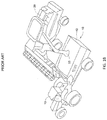
- FIG. 2 is a drawing showing a grain cart 10 with a grain truck 24 .
- Grain carts 10 are large-capacity pull-type trailers with a container 12 for grain 22 , a built-in discharge auger 18 , and capacities currently as high as 2,000 bushels.
- a tractor 13 with grain cart 10 typically shuttles grain 22 from a combine 20 in a field to a grain truck 24 located at the edge of the field.
- the grain carts 10 are typically loaded by or from a combine 20 , and then unloaded into a truck 24 , with combines 20 and trucks 24 typically utilized with one or more grain carts 10 to harvest fields of grain.
- grain carts dramatically increases harvest efficiency, allowing combines 20 to operate nearly continuously with no need to stop to unload, especially since grain carts 10 can be loaded from combines 20 while the combines and the grain cart they are loading move across the field together in a synchronized manner. While the grain cart 10 is away from the combine 20 , the combine may continue to harvest the field, relying on its built-in hopper or grain container to buffer the harvested grain. After unloading to a waiting truck 24 , the grain cart 10 can then head back to receive grain from a (not necessarily the same) combine 20 .
- Grain cart weighing systems currently comprise two parts: weight sensors, and electronics that weigh the load and present information to the user—often called “indicators”.
- weight sensors are typically either load cells or weigh bars.
- a plurality of weight sensors is utilized for each cart.
- Systems offered by market incumbents provide a monolithic measurement and display terminal typically situated in the tractor's cab with wires that connect back to the grain cart weight sensors, which may have been combined through a passive junction box.
- standard weigh scale functions are provided including: zero; tare; and net/gross toggle.
- Advanced systems provide grain management functions allowing harvesting details to be captured as transactions.
- FIG. 3 is a graph that illustrates the measurement dynamics that may be experienced while traversing a rough field, which contaminate the accuracy of the measured payload weight. This chart is an example of how measured weight can bounce around as a grain cart moves across a field. Weight sensors measure force, which relates to mass and any applied accelerations including that of gravity and those of vehicle dynamics encountered when a cart traverses uneven ground.
- a scale display terminal is useful in both the loading (from combine) and unloading (to truck) phases
- a single display cannot be positioned so that it may be viewed practically in both phases because the operator faces in opposing directions due to the relative locations of combine and truck during loading and unloading.
- either two displays are required, which is complicated and costly, or the operator must split his attention between the display and the grain transfer itself, which is error prone and inefficient.
- This patent discloses and claims a useful, novel, and unobvious invention for improved weighing and related operational and data management functionality in the farm vehicle field.
- weight and simultaneous three-axis accelerometer measurements are used to compensate for at least some of the effect of non-level or rough terrain.
- a method automatically detects weights of grain transactions by differencing the weight signal as processed by two parallel low pass filters, each with different pass characteristics.
- a method of equipment usage tracking involves the use of beacons and signal strength detection as an indicator of proximity and therefore equipment identification.
- a method for estimating a combine's current fill level involves tracking combine performance using load weight per unit time and per unit area harvested.
- a method for electrically testing weigh bars installed on a grain cart is presented.
- FIGS. 1A and 1B are drawings that show a combine 20 loading grain 22 into a grain cart 10 ;
- FIG. 2 is a drawing showing a grain cart 10 with a grain truck 24 ;
- FIG. 3 is a graph that illustrates the measurement dynamics that may be experienced while traversing a rough field
- FIG. 4 is a drawing showing a grain cart 10 with weight sensors 14 installed, in accordance with an exemplary embodiment of the present invention
- FIG. 5 is a drawing similar to the drawing shown in FIG. 3 , with a line fit to the data points utilizing least-squares;
- FIG. 6A is a diagram that shows a standard weighbridge
- FIG. 6B is a diagram that shows diagnostic circuitry on a half bridge, in accordance with one embodiment of the present invention.
- FIGS. 7A and 7B are drawings that illustrate a tablet showing loading/unloading information.
- FIG. 7A shows the tablet normally, and
- FIG. 7B shows the tablet reversed.
- the present invention differs from solutions offered by others as it does not have a monolithic topology, but instead uses a mobile device as the display terminal, user interface, and processing engine, and which connects wirelessly to electronics located on a grain cart.
- the signals from weight sensors are combined through use of a junction box; the resulting signal is then forwarded to the electronics for measurement, conversion, and transmission to the mobile device.
- Leveraging mobile devices in the present invention reduces product cost, increases processing capacity, and provides advanced data connectivity and navigational capabilities, while enhancing customer familiarity and thus market acceptance.
- This topology is shown in FIG. 4 .
- Exemplary embodiments of the present invention can include techniques to assist with achieving improved weight and mass measurements as described below, using accelerometer-compensated mass measurement.
- One exemplary embodiment uses STmicroelectronics LIS3DH three-axis accelerometer integrated circuits as part of a printed circuit board, with one three-axis accelerometer mounted preferably near each of the weight sensors.
- FIG. 4 is a drawing showing a grain cart 10 with weight sensors 14 installed, in accordance with an exemplary embodiment of the present invention.
- the signals from each of the weight sensors are received by interface electronics with on-board three-axis accelerometer 16 .
- the interface electronics 16 perform signal measurement, conversion, and transmission of the signals to a mobile device that may be located in the tractor 13 towing the grain cart 10 .
- Bluetooth Low Energy (BLE) is utilized to transmit the signals wirelessly.
- BLE Bluetooth Low Energy
- Other transmission means are also within the scope of the present invention.
- the mobile device 17 receiving the signals is a tablet, such as an iPad. Other mobile devices 17 are also within the scope of the present invention.
- the device 17 typically utilized in the cab of the tractor 13 is mobile, it can also be permanently installed. Moreover, it can relay the information received, and the results of calculations and computations performed to other devices wirelessly or with a wired connection at a future time, for example, at the end of the work day.
- m is the total mass of payload and carrier
- F is the total instantaneous force of the payload and carrier weights as seen by the weight sensors
- a is the instantaneous acceleration projected along the axis of measurement of the weight sensors
- Accelerations projected along the axis of measurement of the weight sensor(s) (a) can be determined by performing the scalar product (dot product) of the measured acceleration and the reference gravity vector, which aligns with the axis of measurement of the weight sensors due to the mounting method described above, and then dividing by the magnitude of the reference gravity vector.
- Equation 1 can be rearranged to yield mass as follows:
- the total force (F) is measured with respect to the weight offset (the measured value seen under free fall).
- the weight offset occurs at the point of zero acceleration, and represents offsets in the measurement apparatus including those of the weigh bars, amplifiers, and data converters.
- the total force (F) can thus be expanded to reflect the raw measured force (F MEAS ) and weight offset (k) as follows:
- FIG. 5 is a drawing similar to the drawing shown in FIG. 3 , with a line fit to the data points utilizing least-squares.
- the weight offset (k) that is determined can be low-pass filtered over subsequent measurements to reduce the noise bandwidth.
- the filter's corner frequency can be set quite low, since “k” does not vary while mass is constant.
- the input data may be gated (manually or automatically) to ensure that the mass remains constant.
- the bandwidths of the weight and acceleration sensors should preferably be matched and the sampling time should be synchronized.
- evaluation of the above equations is performed within a processor of the electronics in order to coordinate the measurements and reduce the needed radio bandwidth.
- the compensated measurements may then be forwarded to the mobile device in the tractor cab.
- Exemplary methods of the present invention may include techniques to aid in tracking and auditing field operations as described below.
- an exemplary method for automatically determining the particular equipment used in an operation is disclosed herein (for non-limiting example, a combine, truck, or trailer).
- a wireless beacon device is placed on each piece of equipment, a receiver is located at or near the operator, and the system automatically selects from a list of allowed equipment types (for non-limiting example: combines or perhaps trucks) the equipment associated with the beacon of highest signal strength as the equipment used in an operation.
- the combine currently loading the cart can be detected as closest and thus assigned to the transaction.
- a truck receiving the grain can be detected as the closest truck and thus assigned to the transaction.
- time, location, and event details for example transactional weight
- a list of detected equipment could be presented to the user and a selection by the user could be used to determine the equipment used in the operation. Before being presented to the user this list could be further limited to detected equipment where the associated beacon signal strength exceeds a threshold. This may be useful in cases where equipment is in close proximity such as when multiple trucks are waiting to be loaded with grain. In the case where only a single equipment has a beacon signal exceeding the threshold that equipment could be automatically determined as the equipment used in the operation.
- the exemplary method uses stand-alone Bluetooth Low Energy (BLE) beacons, such as those currently available from Gelo Inc., mounted to each piece of equipment, and configured to periodically provide its identity.
- BLE Bluetooth Low Energy
- a mobile device mounted in the tractor cab monitors the announcements (e.g. Bluetooth “advertisements”) and processes the events in the manner disclosed in order to determine the nearest equipment.
- Other embodiments could include using an additional mobile device, acting as a beacon, mounted in the cab of the equipment being monitored (the truck or combine cab for non-limiting example). This is exemplary, and other configurations and implementations are also within the scope of the present invention.
- Another exemplary method is used to estimate the combine's current fill level while harvesting in order to facilitate operations in the field.
- the method can predict combine fill level using linear extrapolation as follows:
- ⁇ circumflex over (F) ⁇ is the estimate of combine fill weight with time (t) since the last load
- ⁇ F LOAD is the accumulated weight of the N most recent loads
- ⁇ t LOAD is the time between the most recent load and the one preceding the N th last load.
- This exemplary method uses a value of one (1) for the window size (N).
- This exemplary method uses the processor of the mobile device to process weights of loads and the time between such in order that it estimate the combine's current fill level.
- Other configurations are also within the scope of the present invention.
- This estimate can be improved by instead using GPS locations services so that the system tracks combine performance per unit of field area harvested instead of per unit time. In this case, combine performance is rated as load weight per area harvested between loads.
- This method can predict combine fill level using linear extrapolation as follows:
- ⁇ circumflex over (F) ⁇ is the estimate of combine fill weight with area harvested (a) since the last load
- ⁇ F LOAD is the accumulated weight of the N most recent loads
- ⁇ a LOAD is the area harvested between the most recent load and the one preceding the N th last load.
- This exemplary method uses a value of one (1) for the window size (N).
- This exemplary method computes the area harvested as the line-integral of the path traveled, multiplied by the harvester's header width, subtracting that portion of the swath that overlapped previously harvested swaths. The overlap is determined using a high-resolution grid representing the field whereby each harvested grid location gets marked so as to be excluded on subsequent paths.
- This exemplary method uses a grid size of one foot (1′) squared. Other configurations are also within the scope of this invention.
- This exemplary method uses the processor of a mobile device in the tractor cab to process weights of loads as measured, along with the combine's current GPS location as measured and forwarded from a mobile device, mounted in the combine cab, over the wireless Internet cellular infrastructure.
- This is exemplary, and other configurations are also within the scope of the present invention.
- the method further includes directing a grain cart to unload a first combine when the current fill level for the first combine exceeds a pre-specified threshold.
- the method further includes calculating an estimate of the current fill level for a second combine in the same manner as the estimate for the current fill level for the first combine was calculated; calculating a maximum estimated fill level from the estimated fill levels of each of a set of combines that comprise the first combine and the second combine; and directing a grain cart to a one of the set of combines corresponding to the maximum estimated fill level.
- Exemplary embodiments of the present invention may include a technique to electrically test the weigh bars or load cells while installed on the grain cart.
- the technique performs operations to test all four resistors that form the standard weighbridge arrangement.
- the technique will also work where multiple weigh bars or load cells of a cart are wired in parallel (all like terminals wired together), so that the measured value for each weighbridge resistor approximates that of the parallel combination of all like resistors. This makes the measurement less sensitive by a factor of approximately the total number of weigh bars, and so measurement precision must be sufficient to reveal any anomalies.
- FIG. 6A is a diagram that shows a standard weighbridge.
- FIG. 6B is a diagram that shows diagnostic circuitry on a half bridge, in accordance with one embodiment of the present invention.
- the analysis preferably splits the weighbridge symmetrically into left and right halves (see FIG. 6B ). This is possible because the excitation connections are typically low impedance voltage sources (in the exemplary embodiment, positive and ground voltage rails).
- FIG. 6B the voltmeter (circle with “V”) of the full bridge ( FIG. 6A ) has been decomposed into the buffer (BUF) and analog to digital converter (ADC) of the half bridge.
- BAF buffer
- ADC analog to digital converter
- the analysis solves for the two half bridge resistors by measuring the voltage at the midpoint under various conditions and with different voltage references.
- the first step measures the ratio of the voltage divider formed by the two resistors while the current source is disabled. This is done using the excitation voltage (V CC and Ground) as the reference for the ADC.
- the next step uses a fixed voltage reference (often available internal to the ADC) and the ADC to measure the voltage at the midpoint of the half bridge while the current source is disconnected. This step is repeated with the current source connected.
- the value of the top resistor can then be found as follows:
- R TOP is the resistance of the top resistor
- V MID1 and V MID2 are the voltages measured at the midpoint of the half bridge with the switch open and closed respectively
- I is the value of the constant current source
- RATIO is the measured ratio of the midpoint voltage with respect to the excitation voltage, with no current source.
- the value of the bottom resistor can be found as follows:
- R BOT ( V MID2 ⁇ V MID1 )/( I *(1 ⁇ RATIO)) (8)
- V MID1 , V MID2 , I, and RATIO are defined previously, and R BOT is the resistance of the bottom resistor.
- the processor of the electronics can perform the health measurements as directed by a mobile device in the tractor cab. Other configurations are also within the scope of the present invention.
- Exemplary embodiments may also include a method to isolate individual weight sensors that have been combined as would be done through use of a junction box 15 (see FIG. 4 ), so that health detection can be performed on individual weight sensors in order to provide more thorough diagnostic capability.
- This embodiment involves replacing the passive junction box for which the like terminals of all weight sensors are permanently joined, with instead an active junction box whereby all connections for each weight sensor can be individually connected to (or disconnected from) the measurement electronics through use of digitally controlled switches, in order to present any possible combination of the weigh bars.
- the measurement electronics control the switches of the active junction box. This is exemplary, and other configurations are also within the scope of the present invention.
- the invention can be utilized to trouble shoot weight sensors that do not appear to be operating correctly. Pairs of resisters in the half bridges are serially tested, with note being taken whenever the results of the testing are problematic.
- the weight sensors are tested on a routine or somewhat routine basis. For example, they may be tested on a periodic basis, or may be tested daily whenever the system is started. Other alternatives are also within the scope of the invention.
- a controller may send an alert when problems are discovered, or flags or codes set indicating problems. This allows weight sensors to be repaired or replaced before they fail or are inaccurate enough to affect operations. Other configurations and alternate usages are also within the scope of the present invention.
- Exemplary embodiments of the present invention may include a method to increase the diversity of display locations while in operation.
- a display is located for convenient viewing in one of the two grain transfer phases (loading or unloading).
- the operator views the display through a mirror positioned at an angle that is convenient for viewing during that phase; the mirror reflects an image that is deliberately reversed by the display equipment so that it becomes restored through reflection.
- Control of the reversing process could be applied automatically to reduce the burden on the equipment operator.
- reversing control could be linked to the automatic transaction detection method whereby the display is automatically reversed while unloading.
- the display would be mounted for convenient viewing during loading (combine to cart), and the mirror used while unloading (cart to truck).
- the opposite scenario would also be possible, whereby the mounting locations and reversing control are each reversed.
- Other configurations are also within the scope of the present invention.
- FIG. 7A is a drawing that illustrates a tablet showing loading/unloading information.
- FIG. 7B is a drawing showing the same tablet shown in FIG. 7A , but reversed.
- the information shown in these displays is exemplary, and the display of other information and other configurations of the display are also within the scope of the present invention.
- a user selectable element such as a button or checkbox could be present in the user interface allowing the user to manually choose between the regular and reversed display. This may be useful for testing purposes, in the case the automatic detection fails to work, or simple user preference.
- the device could also be configurable to disable one or more of the display reverse methods. For example, a user may desire to disable the automatic reverse because it is not useful in their work scenario. In another example, a user may desire to disable the user-selectable element because the automatic reverse meets their needs and they want more room on the display. This configurability could be present via an options or configuration menu in the user interface. Other configurations and options are also within the scope of the present invention.
- the present invention is targeted at grain cart applications, but is equally applicable for use with other equipment, such as combines, trucks, planters, air seeders, and seed tenders. These types of equipment are exemplary, and other types are also within the scope of the present invention. In all cases, the invention can improve weighing performance, data quality, sensor diagnostics, and automates and enhances field operations.
Landscapes
- Engineering & Computer Science (AREA)
- General Physics & Mathematics (AREA)
- Physics & Mathematics (AREA)
- Business, Economics & Management (AREA)
- Economics (AREA)
- Human Resources & Organizations (AREA)
- Strategic Management (AREA)
- Marketing (AREA)
- Theoretical Computer Science (AREA)
- General Business, Economics & Management (AREA)
- Tourism & Hospitality (AREA)
- Entrepreneurship & Innovation (AREA)
- Operations Research (AREA)
- Development Economics (AREA)
- Quality & Reliability (AREA)
- Radar, Positioning & Navigation (AREA)
- Remote Sensing (AREA)
- Animal Husbandry (AREA)
- Life Sciences & Earth Sciences (AREA)
- Agronomy & Crop Science (AREA)
- Computer Networks & Wireless Communication (AREA)
- Marine Sciences & Fisheries (AREA)
- Mining & Mineral Resources (AREA)
- Health & Medical Sciences (AREA)
- General Health & Medical Sciences (AREA)
- Primary Health Care (AREA)
- Educational Administration (AREA)
- Game Theory and Decision Science (AREA)
- Arrangements For Transmission Of Measured Signals (AREA)
- Handcart (AREA)
Abstract
Description
- This application is a continuation under 37 C.F.R. § 1.53(b) of U.S. patent application Ser. No. 15/526,731 filed May 12, 2017 now U.S. Pat. No. ______, the entire disclosure of which is hereby incorporated by reference, which is a National Phase entry under 35 U.S.C. § 371(c) of PCT Application No. PCT/CA2014/000810, filed Nov. 14, 2014, the entire disclosure of which is incorporated by reference herein.
- The present invention relates to weighing dynamic loads and, more specifically, to apparatus and method for weighing grain cart loads.
-
FIGS. 1A and 1B are drawings that show acombine 20loading grain 22 from a field ofgrain 23 into agrain cart 10.FIG. 2 is a drawing showing agrain cart 10 with agrain truck 24.Grain carts 10 are large-capacity pull-type trailers with acontainer 12 forgrain 22, a built-indischarge auger 18, and capacities currently as high as 2,000 bushels. Atractor 13 withgrain cart 10 typically shuttlesgrain 22 from acombine 20 in a field to agrain truck 24 located at the edge of the field. Thegrain carts 10 are typically loaded by or from acombine 20, and then unloaded into atruck 24, withcombines 20 andtrucks 24 typically utilized with one ormore grain carts 10 to harvest fields of grain. The use of grain carts dramatically increases harvest efficiency, allowing combines 20 to operate nearly continuously with no need to stop to unload, especially sincegrain carts 10 can be loaded fromcombines 20 while the combines and the grain cart they are loading move across the field together in a synchronized manner. While thegrain cart 10 is away from thecombine 20, the combine may continue to harvest the field, relying on its built-in hopper or grain container to buffer the harvested grain. After unloading to a waitingtruck 24, thegrain cart 10 can then head back to receive grain from a (not necessarily the same)combine 20. - Early adopters experimented with cart-based weighing systems, which quickly became standard equipment currently on roughly 80% of grain carts built in-factory. Weighing systems for grain carts allow the tracking of yields and help ensure that operators can accurately fill the truck to capacity with little risk of incurring fines for overweight loads. Grain carts make the use of combines more efficient; weighing systems can help make the whole process more efficient.
- Grain cart weighing systems currently comprise two parts: weight sensors, and electronics that weigh the load and present information to the user—often called “indicators”. Currently, weight sensors are typically either load cells or weigh bars. Typically, a plurality of weight sensors is utilized for each cart. In one typical configuration, there is one weight sensor for each wheel and one for the tow bar or hitch. In another typical configuration, there is a plurality of weight sensors spread out around the grain cart container. Systems offered by market incumbents provide a monolithic measurement and display terminal typically situated in the tractor's cab with wires that connect back to the grain cart weight sensors, which may have been combined through a passive junction box. In their simplest form, standard weigh scale functions are provided including: zero; tare; and net/gross toggle. Advanced systems provide grain management functions allowing harvesting details to be captured as transactions.
- However, while conventional methods and technologies have gained significant market acceptance, it has been noted that there are numerous issues with the current state of the art. Some of the recognized problems are as follows:
- Measurement Dynamics.
- While on-board weighing systems can generally provide accurate static measurements on level ground, weight measurements can be compromised by forces that originate either on-cart (auger operation) or from accelerations due to drops and impacts with obstacles on uneven terrain. The degree of measurement contamination relates to the specific terrain, cart resonances, and vehicle velocity—higher speeds having a more significant adverse impact on accuracy.
FIG. 3 is a graph that illustrates the measurement dynamics that may be experienced while traversing a rough field, which contaminate the accuracy of the measured payload weight. This chart is an example of how measured weight can bounce around as a grain cart moves across a field. Weight sensors measure force, which relates to mass and any applied accelerations including that of gravity and those of vehicle dynamics encountered when a cart traverses uneven ground. When a bump results in an upward acceleration the weight sensors see an increased force, and when downward, a decreased force. This is true even if it were possible to maintain the alignment of the weight sensor toward the center of the earth. Even while stopped, uneven ground can result in inaccurate weight measurement, since the axis of sensitivity of the weighing sensor becomes misaligned with the gravity vector. This typically results in only a fraction of the load being measured by the weighing sensor, since the acceleration or force vector is no longer in just the direction of the axis of sensitivity of the weight sensor, but may include components in other directions. - Operations Tracking.
- Lack of identification of the harvesting equipment (combine and truck) involved in grain transactions limits the usefulness of the collected management information. Although a grain cart operator could record such information manually, operator error due to the monotony and exhaustion suffered by cart operators leaves manually collected data unreliable.
- No telemetric operational coordination currently exists between grain cart and combine. The efficiency of harvest operations could be increased through reception (or prediction) of combine fill-level and location for display to the grain cart operator.
- Pre-Emptive Weigh Bridge Failure Detection.
- Quality on-cart grain weighing is predicated on having functional weight sensors, such as weigh bars. Over time, these devices can fail by delamination of the internal strain gauges, vibrational stresses harming internal wiring, or by physical damage to the bar or external wiring. The damage can occur slowly or abruptly depending on the failure mode, but in all cases ultimately affects the weighing performance. The operator may misdiagnose slow or even the catastrophic failures and compensate for resulting measurement drifts or offsets by re-zeroing the scale indicator. Such remedies can result in weight inaccuracies and erroneous farm management data. If pre-emptively and properly diagnosed, defective sensors and wiring can be replaced before they impact production. However, there is no automated system or methodology available to detect and isolate this problem.
- Display Location Diversity.
- Although a scale display terminal is useful in both the loading (from combine) and unloading (to truck) phases, a single display cannot be positioned so that it may be viewed practically in both phases because the operator faces in opposing directions due to the relative locations of combine and truck during loading and unloading. Currently, either two displays are required, which is complicated and costly, or the operator must split his attention between the display and the grain transfer itself, which is error prone and inefficient.
- What is needed, therefore, is a method or methods that can address the above identified problems in the current state of the art.
- This patent discloses and claims a useful, novel, and unobvious invention for improved weighing and related operational and data management functionality in the farm vehicle field.
- According to a first aspect of the present invention, weight and simultaneous three-axis accelerometer measurements are used to compensate for at least some of the effect of non-level or rough terrain.
- According to a second aspect of the present invention, a method automatically detects weights of grain transactions by differencing the weight signal as processed by two parallel low pass filters, each with different pass characteristics.
- According to a third aspect of the present invention, a method of equipment usage tracking involves the use of beacons and signal strength detection as an indicator of proximity and therefore equipment identification.
- According to a fourth aspect of the present invention, a method for estimating a combine's current fill level involves tracking combine performance using load weight per unit time and per unit area harvested.
- According to a fifth aspect of the present invention, a method is presented for electrically testing weigh bars installed on a grain cart.
- A detailed description of exemplary embodiments of the present invention is given in the following. It is to be understood, however, that the invention is not to be construed as being limited to these embodiments.
-
FIGS. 1A and 1B are drawings that show acombine 20loading grain 22 into agrain cart 10; -
FIG. 2 is a drawing showing agrain cart 10 with agrain truck 24; -
FIG. 3 is a graph that illustrates the measurement dynamics that may be experienced while traversing a rough field; -
FIG. 4 is a drawing showing agrain cart 10 withweight sensors 14 installed, in accordance with an exemplary embodiment of the present invention; -
FIG. 5 is a drawing similar to the drawing shown inFIG. 3 , with a line fit to the data points utilizing least-squares; -
FIG. 6A is a diagram that shows a standard weighbridge; -
FIG. 6B is a diagram that shows diagnostic circuitry on a half bridge, in accordance with one embodiment of the present invention; and -
FIGS. 7A and 7B are drawings that illustrate a tablet showing loading/unloading information.FIG. 7A shows the tablet normally, andFIG. 7B shows the tablet reversed. - The present invention differs from solutions offered by others as it does not have a monolithic topology, but instead uses a mobile device as the display terminal, user interface, and processing engine, and which connects wirelessly to electronics located on a grain cart. The signals from weight sensors are combined through use of a junction box; the resulting signal is then forwarded to the electronics for measurement, conversion, and transmission to the mobile device. Leveraging mobile devices in the present invention reduces product cost, increases processing capacity, and provides advanced data connectivity and navigational capabilities, while enhancing customer familiarity and thus market acceptance. This topology is shown in
FIG. 4 . - Exemplary embodiments of the present invention will now be described with reference to the appended drawings.
- Measurement Dynamics.
- Exemplary embodiments of the present invention can include techniques to assist with achieving improved weight and mass measurements as described below, using accelerometer-compensated mass measurement.
- Effects of non-level orientation and in-motion vibration can be reduced from mass measurements by compensating weight measurements with simultaneous accelerometer measurements, given matching bandwidths. One exemplary embodiment uses STmicroelectronics LIS3DH three-axis accelerometer integrated circuits as part of a printed circuit board, with one three-axis accelerometer mounted preferably near each of the weight sensors.
-
FIG. 4 is a drawing showing agrain cart 10 withweight sensors 14 installed, in accordance with an exemplary embodiment of the present invention. The signals from each of the weight sensors are received by interface electronics with on-board three-axis accelerometer 16. Theinterface electronics 16 perform signal measurement, conversion, and transmission of the signals to a mobile device that may be located in thetractor 13 towing thegrain cart 10. In one embodiment of the present invention, Bluetooth Low Energy (BLE) is utilized to transmit the signals wirelessly. Other transmission means are also within the scope of the present invention. In one embodiment of the present invention, themobile device 17 receiving the signals is a tablet, such as an iPad. Othermobile devices 17 are also within the scope of the present invention. Moreover, while thedevice 17 typically utilized in the cab of thetractor 13 is mobile, it can also be permanently installed. Moreover, it can relay the information received, and the results of calculations and computations performed to other devices wirelessly or with a wired connection at a future time, for example, at the end of the work day. - Newton's law of motion is applied as follows in a preferred embodiment:
-
F=m*a (1) - where “m” is the total mass of payload and carrier; “F” is the total instantaneous force of the payload and carrier weights as seen by the weight sensors; and “a” is the instantaneous acceleration projected along the axis of measurement of the weight sensors
- Two exemplary methods are shown below sharing various commonalities. Common to both exemplary methods are sensor mounting, determination of reference gravity vector, and projection of the instantaneous acceleration measurements along the reference gravity vector.
- Sensor Mounting:
- Sensors are to be mounted as follows in the exemplary methods:
-
- (1) Mount each single-axis weight sensor so that it is most sensitive in the downward direction (toward the center of the Earth) while the cart is stationary and on level ground. Other configurations are also within the scope of the present invention. However, this configuration is preferred, since it easily allows a reference acceleration vector that aligns with the axis of sensitivity of the weighing sensors to be recorded when stopped on level ground.
- (2) Mount one or more three-axis accelerometers in a convenient orientation on the cart. In a preferred embodiment, one accelerometer is mounted coincident with each weight sensor, and a correction is preferably performed on the data from each weight and accelerometer sensor pair. Other configurations are also within the scope of the present invention.
- Determination of Reference Gravity Vector:
- Measure and record a vector of the static acceleration due to gravity while stationary and on level ground.
- Projection of Accelerations Along the Axis of Measurement of the Weight Sensors:
- Accelerations projected along the axis of measurement of the weight sensor(s) (a) can be determined by performing the scalar product (dot product) of the measured acceleration and the reference gravity vector, which aligns with the axis of measurement of the weight sensors due to the mounting method described above, and then dividing by the magnitude of the reference gravity vector.
- In the first exemplary method,
Equation 1 can be rearranged to yield mass as follows: -
m=F/a (2) - The total force (F) is measured with respect to the weight offset (the measured value seen under free fall). The weight offset occurs at the point of zero acceleration, and represents offsets in the measurement apparatus including those of the weigh bars, amplifiers, and data converters. The total force (F) can thus be expanded to reflect the raw measured force (FMEAS) and weight offset (k) as follows:
-
m=(F MEAS −k)/a (3) - While it is impractical to measure the weight offset directly, a method is disclosed to find it as follows:
- 1) While traveling with constant mass over rough terrain, record weight (FMEAS) and acceleration data pairs.
- 2) Compute the projections of the acceleration data on the axis of measurement of the weight sensors.
- 3) Estimate the weight offset (k) by computing the y-intercept of the least-squares line estimate of weight (FMEAS) and projected accelerations (see
FIG. 5 ). -
FIG. 5 is a drawing similar to the drawing shown inFIG. 3 , with a line fit to the data points utilizing least-squares. Once the weight offset (k) is known, the total mass (or weight under constant and known acceleration) can be determined by the following: - 1) Measure the instantaneous weight (FMEAS) and acceleration (a) data pair.
- 2) Compute the projection of the acceleration on the axis of measurement of the weight sensors.
- 3) Compute the total mass (m) using equation 3.
- A second method requires no regression. Instead, two weight (FMEAS) and acceleration (a) data pairs can be measured while traveling with constant mass, and the accelerations projected along the axis of measurement of the weight sensors (a). This provides two simultaneous equations and two unknowns based on Equation 3, thus allowing a solution for constant “k” using linear algebra techniques as follows:
-
k=(F MEAS1 *a 2 −F MEAS2 *a 1)/(a 2 −a 1) (4) - The weight offset (k) that is determined can be low-pass filtered over subsequent measurements to reduce the noise bandwidth. The filter's corner frequency can be set quite low, since “k” does not vary while mass is constant. The input data may be gated (manually or automatically) to ensure that the mass remains constant. Once the weight offset (k) has been determined to be sufficiently well characterized (it no longer changes significantly), the total mass (or weight under constant and known acceleration) can be determined using Equation 3.
- With either exemplary method, the bandwidths of the weight and acceleration sensors should preferably be matched and the sampling time should be synchronized. In the exemplary embodiment, evaluation of the above equations is performed within a processor of the electronics in order to coordinate the measurements and reduce the needed radio bandwidth. The compensated measurements may then be forwarded to the mobile device in the tractor cab.
- Automatic Operations Tracking.
- Exemplary methods of the present invention may include techniques to aid in tracking and auditing field operations as described below.
- Automatic Equipment Determination.
- For the purpose of automating tracking and auditing, an exemplary method for automatically determining the particular equipment used in an operation is disclosed herein (for non-limiting example, a combine, truck, or trailer). According to this exemplary method, a wireless beacon device is placed on each piece of equipment, a receiver is located at or near the operator, and the system automatically selects from a list of allowed equipment types (for non-limiting example: combines or perhaps trucks) the equipment associated with the beacon of highest signal strength as the equipment used in an operation.
- For a non-limiting example, while loading in the field, the combine currently loading the cart can be detected as closest and thus assigned to the transaction. Similarly, while unloading, a truck receiving the grain can be detected as the closest truck and thus assigned to the transaction. Combined with the time, location, and event details (for example transactional weight) a detailed audit trail can be provided for field operations.
- In another non-limiting example, a list of detected equipment could be presented to the user and a selection by the user could be used to determine the equipment used in the operation. Before being presented to the user this list could be further limited to detected equipment where the associated beacon signal strength exceeds a threshold. This may be useful in cases where equipment is in close proximity such as when multiple trucks are waiting to be loaded with grain. In the case where only a single equipment has a beacon signal exceeding the threshold that equipment could be automatically determined as the equipment used in the operation.
- The exemplary method uses stand-alone Bluetooth Low Energy (BLE) beacons, such as those currently available from Gelo Inc., mounted to each piece of equipment, and configured to periodically provide its identity. A mobile device mounted in the tractor cab monitors the announcements (e.g. Bluetooth “advertisements”) and processes the events in the manner disclosed in order to determine the nearest equipment. Other embodiments could include using an additional mobile device, acting as a beacon, mounted in the cab of the equipment being monitored (the truck or combine cab for non-limiting example). This is exemplary, and other configurations and implementations are also within the scope of the present invention.
- Estimation of Combine Fill Level.
- Another exemplary method is used to estimate the combine's current fill level while harvesting in order to facilitate operations in the field. By tracking the performance of each combine (load weight per unit time), the method can predict combine fill level using linear extrapolation as follows:
-
{circumflex over (F)}(t)=ΣF LOAD /Δt LOAD *r (5) - Where {circumflex over (F)} is the estimate of combine fill weight with time (t) since the last load; ΣFLOAD is the accumulated weight of the N most recent loads; and ΔtLOAD is the time between the most recent load and the one preceding the Nth last load.
- This exemplary method uses a value of one (1) for the window size (N). This exemplary method uses the processor of the mobile device to process weights of loads and the time between such in order that it estimate the combine's current fill level. Other configurations are also within the scope of the present invention. This estimate can be improved by instead using GPS locations services so that the system tracks combine performance per unit of field area harvested instead of per unit time. In this case, combine performance is rated as load weight per area harvested between loads. This method can predict combine fill level using linear extrapolation as follows:
-
{circumflex over (F)}(a)=ΣF LOAD /Δc LOAD *a (6) - Where {circumflex over (F)} is the estimate of combine fill weight with area harvested (a) since the last load; ΣFLOAD is the accumulated weight of the N most recent loads; and ΔaLOAD is the area harvested between the most recent load and the one preceding the Nth last load.
- This exemplary method uses a value of one (1) for the window size (N). This exemplary method computes the area harvested as the line-integral of the path traveled, multiplied by the harvester's header width, subtracting that portion of the swath that overlapped previously harvested swaths. The overlap is determined using a high-resolution grid representing the field whereby each harvested grid location gets marked so as to be excluded on subsequent paths. This exemplary method uses a grid size of one foot (1′) squared. Other configurations are also within the scope of this invention.
- This exemplary method uses the processor of a mobile device in the tractor cab to process weights of loads as measured, along with the combine's current GPS location as measured and forwarded from a mobile device, mounted in the combine cab, over the wireless Internet cellular infrastructure. This is exemplary, and other configurations are also within the scope of the present invention.
- In one embodiment the method further includes directing a grain cart to unload a first combine when the current fill level for the first combine exceeds a pre-specified threshold.
- In another embodiment, the method further includes calculating an estimate of the current fill level for a second combine in the same manner as the estimate for the current fill level for the first combine was calculated; calculating a maximum estimated fill level from the estimated fill levels of each of a set of combines that comprise the first combine and the second combine; and directing a grain cart to a one of the set of combines corresponding to the maximum estimated fill level.
- Although this method requires that information be shared between a combine and a cart, connectivity need not be continuous as the system can fall back to using time-based prediction during periods when the network is unavailable.
- Automatic Weigh Bridge Health Detection.
- Exemplary embodiments of the present invention may include a technique to electrically test the weigh bars or load cells while installed on the grain cart.
- The technique performs operations to test all four resistors that form the standard weighbridge arrangement. The technique will also work where multiple weigh bars or load cells of a cart are wired in parallel (all like terminals wired together), so that the measured value for each weighbridge resistor approximates that of the parallel combination of all like resistors. This makes the measurement less sensitive by a factor of approximately the total number of weigh bars, and so measurement precision must be sufficient to reveal any anomalies.
-
FIG. 6A is a diagram that shows a standard weighbridge.FIG. 6B is a diagram that shows diagnostic circuitry on a half bridge, in accordance with one embodiment of the present invention. The analysis preferably splits the weighbridge symmetrically into left and right halves (seeFIG. 6B ). This is possible because the excitation connections are typically low impedance voltage sources (in the exemplary embodiment, positive and ground voltage rails). - In
FIG. 6B , the voltmeter (circle with “V”) of the full bridge (FIG. 6A ) has been decomposed into the buffer (BUF) and analog to digital converter (ADC) of the half bridge. - The analysis solves for the two half bridge resistors by measuring the voltage at the midpoint under various conditions and with different voltage references. The first step measures the ratio of the voltage divider formed by the two resistors while the current source is disabled. This is done using the excitation voltage (VCC and Ground) as the reference for the ADC.
- The next step uses a fixed voltage reference (often available internal to the ADC) and the ADC to measure the voltage at the midpoint of the half bridge while the current source is disconnected. This step is repeated with the current source connected.
- Using network analysis techniques, the value of the top resistor can then be found as follows:
-
R TOP(V MID2 −V MID1)/(I*RATIO) (7) - Where RTOP is the resistance of the top resistor; VMID1 and VMID2 are the voltages measured at the midpoint of the half bridge with the switch open and closed respectively; I is the value of the constant current source; and RATIO is the measured ratio of the midpoint voltage with respect to the excitation voltage, with no current source.
- Similarly, the value of the bottom resistor can be found as follows:
-
R BOT=(V MID2 −V MID1)/(I*(1−RATIO)) (8) - Where VMID1, VMID2, I, and RATIO are defined previously, and RBOT is the resistance of the bottom resistor. In this exemplary embodiment, the processor of the electronics can perform the health measurements as directed by a mobile device in the tractor cab. Other configurations are also within the scope of the present invention.
- Exemplary embodiments may also include a method to isolate individual weight sensors that have been combined as would be done through use of a junction box 15 (see
FIG. 4 ), so that health detection can be performed on individual weight sensors in order to provide more thorough diagnostic capability. This embodiment involves replacing the passive junction box for which the like terminals of all weight sensors are permanently joined, with instead an active junction box whereby all connections for each weight sensor can be individually connected to (or disconnected from) the measurement electronics through use of digitally controlled switches, in order to present any possible combination of the weigh bars. In the exemplary embodiment, the measurement electronics control the switches of the active junction box. This is exemplary, and other configurations are also within the scope of the present invention. - This invention provides a number of different alternatives and embodiments. In one embodiment, the invention can be utilized to trouble shoot weight sensors that do not appear to be operating correctly. Pairs of resisters in the half bridges are serially tested, with note being taken whenever the results of the testing are problematic. In another embodiment, the weight sensors are tested on a routine or somewhat routine basis. For example, they may be tested on a periodic basis, or may be tested daily whenever the system is started. Other alternatives are also within the scope of the invention. A controller may send an alert when problems are discovered, or flags or codes set indicating problems. This allows weight sensors to be repaired or replaced before they fail or are inaccurate enough to affect operations. Other configurations and alternate usages are also within the scope of the present invention.
- Enhanced Display Location Diversity.
- Exemplary embodiments of the present invention may include a method to increase the diversity of display locations while in operation. A display is located for convenient viewing in one of the two grain transfer phases (loading or unloading). During the other phase, the operator views the display through a mirror positioned at an angle that is convenient for viewing during that phase; the mirror reflects an image that is deliberately reversed by the display equipment so that it becomes restored through reflection. Control of the reversing process could be applied automatically to reduce the burden on the equipment operator. For non-limiting example, reversing control could be linked to the automatic transaction detection method whereby the display is automatically reversed while unloading. In this case, the display would be mounted for convenient viewing during loading (combine to cart), and the mirror used while unloading (cart to truck). The opposite scenario would also be possible, whereby the mounting locations and reversing control are each reversed. Other configurations are also within the scope of the present invention.
-
FIG. 7A is a drawing that illustrates a tablet showing loading/unloading information.FIG. 7B is a drawing showing the same tablet shown inFIG. 7A , but reversed. The information shown in these displays is exemplary, and the display of other information and other configurations of the display are also within the scope of the present invention. - A user selectable element (not shown) such as a button or checkbox could be present in the user interface allowing the user to manually choose between the regular and reversed display. This may be useful for testing purposes, in the case the automatic detection fails to work, or simple user preference.
- The device could also be configurable to disable one or more of the display reverse methods. For example, a user may desire to disable the automatic reverse because it is not useful in their work scenario. In another example, a user may desire to disable the user-selectable element because the automatic reverse meets their needs and they want more room on the display. This configurability could be present via an options or configuration menu in the user interface. Other configurations and options are also within the scope of the present invention.
- The present invention is targeted at grain cart applications, but is equally applicable for use with other equipment, such as combines, trucks, planters, air seeders, and seed tenders. These types of equipment are exemplary, and other types are also within the scope of the present invention. In all cases, the invention can improve weighing performance, data quality, sensor diagnostics, and automates and enhances field operations.
- Those skilled in the art will recognize that modifications and variations can be made without departing from the spirit of the invention. Therefore, it is intended that this invention encompass all such variations and modifications as fall within the scope of the appended claims.
Claims (21)
Priority Applications (3)
| Application Number | Priority Date | Filing Date | Title |
|---|---|---|---|
| US16/983,290 US11274958B2 (en) | 2014-11-14 | 2020-08-03 | System and method for measuring grain cart weight |
| US17/591,287 US11835377B2 (en) | 2014-11-14 | 2022-02-02 | System and method for measuring grain cart weight |
| US18/497,743 US20240060813A1 (en) | 2014-11-14 | 2023-10-30 | System and method for measuring grain cart weight |
Applications Claiming Priority (2)
| Application Number | Priority Date | Filing Date | Title |
|---|---|---|---|
| PCT/CA2014/000810 WO2016074058A1 (en) | 2014-11-14 | 2014-11-14 | System and method for measuring grain cart weight |
| US16/983,290 US11274958B2 (en) | 2014-11-14 | 2020-08-03 | System and method for measuring grain cart weight |
Related Parent Applications (2)
| Application Number | Title | Priority Date | Filing Date |
|---|---|---|---|
| PCT/CA2014/000810 Continuation WO2016074058A1 (en) | 2014-11-14 | 2014-11-14 | System and method for measuring grain cart weight |
| US15/526,731 Continuation US10760946B2 (en) | 2014-11-14 | 2014-11-14 | System and method for measuring grain cart weight |
Related Child Applications (1)
| Application Number | Title | Priority Date | Filing Date |
|---|---|---|---|
| US17/591,287 Continuation US11835377B2 (en) | 2014-11-14 | 2022-02-02 | System and method for measuring grain cart weight |
Publications (2)
| Publication Number | Publication Date |
|---|---|
| US20200363256A1 true US20200363256A1 (en) | 2020-11-19 |
| US11274958B2 US11274958B2 (en) | 2022-03-15 |
Family
ID=55953483
Family Applications (4)
| Application Number | Title | Priority Date | Filing Date |
|---|---|---|---|
| US15/526,731 Active 2036-04-02 US10760946B2 (en) | 2014-11-14 | 2014-11-14 | System and method for measuring grain cart weight |
| US16/983,290 Active 2034-12-15 US11274958B2 (en) | 2014-11-14 | 2020-08-03 | System and method for measuring grain cart weight |
| US17/591,287 Active US11835377B2 (en) | 2014-11-14 | 2022-02-02 | System and method for measuring grain cart weight |
| US18/497,743 Pending US20240060813A1 (en) | 2014-11-14 | 2023-10-30 | System and method for measuring grain cart weight |
Family Applications Before (1)
| Application Number | Title | Priority Date | Filing Date |
|---|---|---|---|
| US15/526,731 Active 2036-04-02 US10760946B2 (en) | 2014-11-14 | 2014-11-14 | System and method for measuring grain cart weight |
Family Applications After (2)
| Application Number | Title | Priority Date | Filing Date |
|---|---|---|---|
| US17/591,287 Active US11835377B2 (en) | 2014-11-14 | 2022-02-02 | System and method for measuring grain cart weight |
| US18/497,743 Pending US20240060813A1 (en) | 2014-11-14 | 2023-10-30 | System and method for measuring grain cart weight |
Country Status (5)
| Country | Link |
|---|---|
| US (4) | US10760946B2 (en) |
| EP (1) | EP3218679A4 (en) |
| AU (3) | AU2014411244B2 (en) |
| CA (1) | CA2967676C (en) |
| WO (1) | WO2016074058A1 (en) |
Cited By (56)
| Publication number | Priority date | Publication date | Assignee | Title |
|---|---|---|---|---|
| US11079725B2 (en) | 2019-04-10 | 2021-08-03 | Deere & Company | Machine control using real-time model |
| US11178818B2 (en) | 2018-10-26 | 2021-11-23 | Deere & Company | Harvesting machine control system with fill level processing based on yield data |
| US11234366B2 (en) | 2019-04-10 | 2022-02-01 | Deere & Company | Image selection for machine control |
| US11240961B2 (en) | 2018-10-26 | 2022-02-08 | Deere & Company | Controlling a harvesting machine based on a geo-spatial representation indicating where the harvesting machine is likely to reach capacity |
| US20220110251A1 (en) | 2020-10-09 | 2022-04-14 | Deere & Company | Crop moisture map generation and control system |
| US11467605B2 (en) | 2019-04-10 | 2022-10-11 | Deere & Company | Zonal machine control |
| US11474523B2 (en) | 2020-10-09 | 2022-10-18 | Deere & Company | Machine control using a predictive speed map |
| US11477940B2 (en) | 2020-03-26 | 2022-10-25 | Deere & Company | Mobile work machine control based on zone parameter modification |
| US11589509B2 (en) | 2018-10-26 | 2023-02-28 | Deere & Company | Predictive machine characteristic map generation and control system |
| US11592822B2 (en) | 2020-10-09 | 2023-02-28 | Deere & Company | Machine control using a predictive map |
| US11635765B2 (en) | 2020-10-09 | 2023-04-25 | Deere & Company | Crop state map generation and control system |
| US11641800B2 (en) | 2020-02-06 | 2023-05-09 | Deere & Company | Agricultural harvesting machine with pre-emergence weed detection and mitigation system |
| US11650587B2 (en) | 2020-10-09 | 2023-05-16 | Deere & Company | Predictive power map generation and control system |
| US11653588B2 (en) | 2018-10-26 | 2023-05-23 | Deere & Company | Yield map generation and control system |
| US11672203B2 (en) | 2018-10-26 | 2023-06-13 | Deere & Company | Predictive map generation and control |
| US11675354B2 (en) | 2020-10-09 | 2023-06-13 | Deere & Company | Machine control using a predictive map |
| US11711995B2 (en) | 2020-10-09 | 2023-08-01 | Deere & Company | Machine control using a predictive map |
| US11727680B2 (en) | 2020-10-09 | 2023-08-15 | Deere & Company | Predictive map generation based on seeding characteristics and control |
| US11825768B2 (en) | 2020-10-09 | 2023-11-28 | Deere & Company | Machine control using a predictive map |
| US11844311B2 (en) | 2020-10-09 | 2023-12-19 | Deere & Company | Machine control using a predictive map |
| US11845449B2 (en) | 2020-10-09 | 2023-12-19 | Deere & Company | Map generation and control system |
| US11849671B2 (en) | 2020-10-09 | 2023-12-26 | Deere & Company | Crop state map generation and control system |
| US11849672B2 (en) | 2020-10-09 | 2023-12-26 | Deere & Company | Machine control using a predictive map |
| US11864483B2 (en) | 2020-10-09 | 2024-01-09 | Deere & Company | Predictive map generation and control system |
| US11874669B2 (en) | 2020-10-09 | 2024-01-16 | Deere & Company | Map generation and control system |
| US11889787B2 (en) | 2020-10-09 | 2024-02-06 | Deere & Company | Predictive speed map generation and control system |
| US11889788B2 (en) | 2020-10-09 | 2024-02-06 | Deere & Company | Predictive biomass map generation and control |
| US11895948B2 (en) | 2020-10-09 | 2024-02-13 | Deere & Company | Predictive map generation and control based on soil properties |
| US11927459B2 (en) | 2020-10-09 | 2024-03-12 | Deere & Company | Machine control using a predictive map |
| US11946747B2 (en) | 2020-10-09 | 2024-04-02 | Deere & Company | Crop constituent map generation and control system |
| US11957072B2 (en) | 2020-02-06 | 2024-04-16 | Deere & Company | Pre-emergence weed detection and mitigation system |
| US11983009B2 (en) | 2020-10-09 | 2024-05-14 | Deere & Company | Map generation and control system |
| US12013245B2 (en) | 2020-10-09 | 2024-06-18 | Deere & Company | Predictive map generation and control system |
| US12035648B2 (en) | 2020-02-06 | 2024-07-16 | Deere & Company | Predictive weed map generation and control system |
| US12058951B2 (en) | 2022-04-08 | 2024-08-13 | Deere & Company | Predictive nutrient map and control |
| US12069986B2 (en) | 2020-10-09 | 2024-08-27 | Deere & Company | Map generation and control system |
| US12069978B2 (en) | 2018-10-26 | 2024-08-27 | Deere & Company | Predictive environmental characteristic map generation and control system |
| US12082531B2 (en) | 2022-01-26 | 2024-09-10 | Deere & Company | Systems and methods for predicting material dynamics |
| US12178158B2 (en) | 2020-10-09 | 2024-12-31 | Deere & Company | Predictive map generation and control system for an agricultural work machine |
| US12229886B2 (en) | 2021-10-01 | 2025-02-18 | Deere & Company | Historical crop state model, predictive crop state map generation and control system |
| US12225846B2 (en) | 2020-02-06 | 2025-02-18 | Deere & Company | Machine control using a predictive map |
| US12245549B2 (en) | 2022-01-11 | 2025-03-11 | Deere & Company | Predictive response map generation and control system |
| US12250905B2 (en) | 2020-10-09 | 2025-03-18 | Deere & Company | Machine control using a predictive map |
| US12284934B2 (en) | 2022-04-08 | 2025-04-29 | Deere & Company | Systems and methods for predictive tractive characteristics and control |
| US12295288B2 (en) | 2022-04-05 | 2025-05-13 | Deere &Company | Predictive machine setting map generation and control system |
| US12298767B2 (en) | 2022-04-08 | 2025-05-13 | Deere & Company | Predictive material consumption map and control |
| US12302791B2 (en) | 2021-12-20 | 2025-05-20 | Deere & Company | Crop constituents, predictive mapping, and agricultural harvester control |
| US12310286B2 (en) | 2021-12-14 | 2025-05-27 | Deere & Company | Crop constituent sensing |
| US12329148B2 (en) | 2020-02-06 | 2025-06-17 | Deere & Company | Predictive weed map and material application machine control |
| US12358493B2 (en) | 2022-04-08 | 2025-07-15 | Deere & Company | Systems and methods for predictive power requirements and control |
| US12386354B2 (en) | 2020-10-09 | 2025-08-12 | Deere & Company | Predictive power map generation and control system |
| US12422847B2 (en) | 2020-10-09 | 2025-09-23 | Deere & Company | Predictive agricultural model and map generation |
| US12419220B2 (en) | 2020-10-09 | 2025-09-23 | Deere & Company | Predictive map generation and control system |
| US12520759B2 (en) | 2022-01-26 | 2026-01-13 | Deere & Company | Systems and methods for predicting material dynamics |
| US12550802B2 (en) | 2020-10-08 | 2026-02-17 | Deere & Company | Predictive machine characteristic map generation and control system |
| US12582035B2 (en) | 2022-04-08 | 2026-03-24 | Deere & Company | Systems and methods for predictive power requirements and control |
Families Citing this family (25)
| Publication number | Priority date | Publication date | Assignee | Title |
|---|---|---|---|---|
| US10612962B2 (en) * | 2017-01-19 | 2020-04-07 | Loginno Logistic Innovation Ltd. | Method of estimating mass of a shipping container and its contents |
| EP3583561A4 (en) * | 2017-04-02 | 2020-09-09 | Takrouri, Thabit | A method and device for tracking the unloading and loading of containers from and onto trucks using motion activity patterns of the containers |
| US10379547B2 (en) | 2017-07-26 | 2019-08-13 | Cnh Industrial Canada, Ltd. | System and method for calibrating a material metering system |
| US10830634B2 (en) | 2018-03-06 | 2020-11-10 | Deere & Company | Fill level detection and control |
| US10736266B2 (en) | 2018-05-31 | 2020-08-11 | Deere & Company | Control of settings on a combine harvester with bias removal |
| US10645864B2 (en) | 2018-08-21 | 2020-05-12 | Cnh Industrial Canada, Ltd. | Product runout tracking system and method |
| DE202018105801U1 (en) * | 2018-10-10 | 2020-01-15 | Trioliet B. V. | Agricultural transport vehicle with weighing system |
| WO2020082182A1 (en) | 2018-10-24 | 2020-04-30 | Bitstrata Systems Inc. | Machine operational state and material movement tracking |
| US10677637B1 (en) * | 2019-04-04 | 2020-06-09 | Scale Tec, Ltd. | Scale controller with dynamic weight measurement |
| US11778945B2 (en) | 2019-04-10 | 2023-10-10 | Deere & Company | Machine control using real-time model |
| US11950538B2 (en) * | 2020-05-19 | 2024-04-09 | Deere & Company | Commodity cart with improved loading positioning |
| US12016264B2 (en) | 2020-07-03 | 2024-06-25 | Deere & Company | Measurement of seeder cart tank contents |
| US20220110258A1 (en) | 2020-10-09 | 2022-04-14 | Deere & Company | Map generation and control system |
| US20220110238A1 (en) | 2020-10-09 | 2022-04-14 | Deere & Company | Machine control using a predictive map |
| US11650093B2 (en) | 2021-01-19 | 2023-05-16 | Scale-Tec Ltd. | Material weight measurement system with automatic tare associated with object presence detection |
| US12127500B2 (en) | 2021-01-27 | 2024-10-29 | Deere & Company | Machine control using a map with regime zones |
| US11066023B1 (en) | 2021-04-09 | 2021-07-20 | INVISIONit LLC | Camera system for particulate material trailer |
| US11980120B2 (en) | 2021-09-03 | 2024-05-14 | Cnh Industrial Canada, Ltd. | Agricultural product storage compartment assembly having a weight monitoring system |
| EP4568467A1 (en) | 2022-08-11 | 2025-06-18 | Deere & Company | Systems and methods for predictive harvesting logistics |
| CA3251651A1 (en) | 2022-08-11 | 2024-02-15 | Deere & Company | Systems and methods for predictive harvesting logistics |
| US12543655B2 (en) | 2022-10-27 | 2026-02-10 | Deere & Company | Controlling transfer of material from a transfer vehicle to a haulage vehicle based on an internal profile of the haulage vehicle |
| US12582033B2 (en) | 2023-04-13 | 2026-03-24 | Deere & Company | Systems and methods for automated grain cart unloading |
| US12472911B2 (en) | 2023-07-11 | 2025-11-18 | Deere & Company | Systems and methods for ground distance control |
| US20250137832A1 (en) * | 2023-10-25 | 2025-05-01 | Deere & Company | Scale based unload rate calculation |
| CN121178010B (en) * | 2025-11-24 | 2026-02-24 | 宁波永固化工有限公司 | Semi-finished product agitator tank of paper tube glue with function of weighing |
Family Cites Families (30)
| Publication number | Priority date | Publication date | Assignee | Title |
|---|---|---|---|---|
| US4455096A (en) * | 1981-11-10 | 1984-06-19 | Brandstedt Controls Corporation | Temperature and operating mode digital display having direct and mirror image viewing capability |
| DE4018520C2 (en) * | 1990-06-09 | 1994-03-31 | Josef Femboeck | Automatic registration system |
| US5837945A (en) * | 1996-04-24 | 1998-11-17 | Hardy Instruments, Inc. | Refuse weighing system and method |
| US5870689A (en) * | 1996-11-22 | 1999-02-09 | Case Corporation | Scouting system for an agricultural field |
| US6124647A (en) * | 1998-12-16 | 2000-09-26 | Donnelly Corporation | Information display in a rearview mirror |
| US7038584B2 (en) | 2000-03-31 | 2006-05-02 | Ge Medical Systems Information Technologies, Inc. | Object location monitoring within buildings |
| US6529164B1 (en) * | 2000-03-31 | 2003-03-04 | Ge Medical Systems Information Technologies, Inc. | Object location monitoring within buildings |
| WO2005062066A2 (en) * | 2003-10-22 | 2005-07-07 | Awarepoint Corporation | Wireless position location and tracking system |
| JP4254475B2 (en) | 2003-10-22 | 2009-04-15 | 株式会社豊田自動織機 | Measurement of remaining amount of gaseous fuel |
| US7507917B2 (en) * | 2004-08-25 | 2009-03-24 | Kaltenheuser Steven R | Apparatus and method for weighing crop on board a harvester |
| US7496439B2 (en) * | 2005-10-17 | 2009-02-24 | Lang Mekra North America, Llc | Multifunction exterior display for a vehicle mirror |
| US7830250B2 (en) | 2007-10-22 | 2010-11-09 | Honeywell International Inc. | Apparatus and method for location estimation using power supply voltage levels of signal transmitters |
| US8032255B2 (en) | 2008-06-30 | 2011-10-04 | Deere & Company | Monitoring of bin level for an agricultural product |
| CN101634586B (en) * | 2008-07-23 | 2011-09-21 | 宇权兴业股份有限公司 | Mass measuring device with gravity correction |
| US20140195256A1 (en) | 2009-04-05 | 2014-07-10 | Awarepoint Corporation | Workflow Context Aware Location Tracking System And Method |
| FR2946742B1 (en) | 2009-06-10 | 2013-06-07 | Quasard Investissements | DEVICE FOR MEASURING THE WEIGHT AND ACCELERATION OF THE CONTENT OF A CONTAINER, METHOD OF MONITORING THE CONTENT. |
| US8823577B2 (en) * | 2009-12-23 | 2014-09-02 | Itrack, Llc | Distance separation tracking system |
| DE102011002884A1 (en) * | 2010-02-08 | 2011-12-15 | Continental Teves Ag & Co. Ohg | Force-and/or pressure-and/or temperature measuring electronic circuit for use in force-and/or pressure- and/or temperature sensors in brake device of motor car, has semi-bridge elements whose metallic resistors form potential divider |
| US10537061B2 (en) * | 2010-02-26 | 2020-01-21 | Cnh Industrial America Llc | System and method for controlling harvest operations |
| US9043096B2 (en) * | 2011-03-31 | 2015-05-26 | Ag Leader Technology | Combine bin level monitoring system |
| EP2511678B1 (en) | 2011-04-12 | 2016-11-23 | Tamtron Oy | Measurement system for a material transfer vehicle |
| AU2012232994A1 (en) * | 2011-09-29 | 2013-04-18 | Stephen William Gale | Weighing system and method of weighing loads |
| US20130124239A1 (en) * | 2011-11-15 | 2013-05-16 | Uriel Rosa | Crop yield per location measurer |
| US9049817B2 (en) * | 2011-12-15 | 2015-06-09 | Cnh Industrial America Llc | Combine unload drive control system |
| US8626406B2 (en) * | 2011-12-22 | 2014-01-07 | Deere & Company | Method and system for transferring material between vehicles |
| US9187259B2 (en) * | 2013-03-15 | 2015-11-17 | Unverferth Manufacturing Company, Inc. | Method for controlling an unload operation on a mobile farm implement |
| US9820436B2 (en) * | 2013-03-27 | 2017-11-21 | Kubota Corporation | Combine for measuring the weight of grain retained in a grain tank |
| WO2015057633A1 (en) * | 2013-10-14 | 2015-04-23 | Kinze Manufacturing, Inc. | Autonomous systems, methods, and apparatus for ag based operations |
| CN203630655U (en) * | 2013-12-12 | 2014-06-04 | 杭州士兰微电子股份有限公司 | Wheatstone bridge device |
| US20150278838A1 (en) * | 2014-04-01 | 2015-10-01 | TekWear, LLC | Systems, methods, and apparatuses for agricultural data collection, analysis, and management via a mobile device |
-
2014
- 2014-11-14 AU AU2014411244A patent/AU2014411244B2/en active Active
- 2014-11-14 US US15/526,731 patent/US10760946B2/en active Active
- 2014-11-14 EP EP14906124.4A patent/EP3218679A4/en not_active Withdrawn
- 2014-11-14 CA CA2967676A patent/CA2967676C/en active Active
- 2014-11-14 WO PCT/CA2014/000810 patent/WO2016074058A1/en not_active Ceased
-
2019
- 2019-02-28 AU AU2019201429A patent/AU2019201429A1/en not_active Abandoned
-
2020
- 2020-08-03 US US16/983,290 patent/US11274958B2/en active Active
-
2021
- 2021-01-05 AU AU2021200034A patent/AU2021200034B2/en active Active
-
2022
- 2022-02-02 US US17/591,287 patent/US11835377B2/en active Active
-
2023
- 2023-10-30 US US18/497,743 patent/US20240060813A1/en active Pending
Cited By (69)
| Publication number | Priority date | Publication date | Assignee | Title |
|---|---|---|---|---|
| US12178156B2 (en) | 2018-10-26 | 2024-12-31 | Deere & Company | Predictive map generation and control |
| US11178818B2 (en) | 2018-10-26 | 2021-11-23 | Deere & Company | Harvesting machine control system with fill level processing based on yield data |
| US12010947B2 (en) | 2018-10-26 | 2024-06-18 | Deere & Company | Predictive machine characteristic map generation and control system |
| US11240961B2 (en) | 2018-10-26 | 2022-02-08 | Deere & Company | Controlling a harvesting machine based on a geo-spatial representation indicating where the harvesting machine is likely to reach capacity |
| US12069978B2 (en) | 2018-10-26 | 2024-08-27 | Deere & Company | Predictive environmental characteristic map generation and control system |
| US12171153B2 (en) | 2018-10-26 | 2024-12-24 | Deere & Company | Yield map generation and control system |
| US11672203B2 (en) | 2018-10-26 | 2023-06-13 | Deere & Company | Predictive map generation and control |
| US11653588B2 (en) | 2018-10-26 | 2023-05-23 | Deere & Company | Yield map generation and control system |
| US11589509B2 (en) | 2018-10-26 | 2023-02-28 | Deere & Company | Predictive machine characteristic map generation and control system |
| US11467605B2 (en) | 2019-04-10 | 2022-10-11 | Deere & Company | Zonal machine control |
| US11650553B2 (en) | 2019-04-10 | 2023-05-16 | Deere & Company | Machine control using real-time model |
| US12495733B2 (en) | 2019-04-10 | 2025-12-16 | Deere & Company | Predictive map and machine control |
| US11829112B2 (en) | 2019-04-10 | 2023-11-28 | Deere & Company | Machine control using real-time model |
| US11234366B2 (en) | 2019-04-10 | 2022-02-01 | Deere & Company | Image selection for machine control |
| US11079725B2 (en) | 2019-04-10 | 2021-08-03 | Deere & Company | Machine control using real-time model |
| US12225846B2 (en) | 2020-02-06 | 2025-02-18 | Deere & Company | Machine control using a predictive map |
| US11641800B2 (en) | 2020-02-06 | 2023-05-09 | Deere & Company | Agricultural harvesting machine with pre-emergence weed detection and mitigation system |
| US12329148B2 (en) | 2020-02-06 | 2025-06-17 | Deere & Company | Predictive weed map and material application machine control |
| US11957072B2 (en) | 2020-02-06 | 2024-04-16 | Deere & Company | Pre-emergence weed detection and mitigation system |
| US12035648B2 (en) | 2020-02-06 | 2024-07-16 | Deere & Company | Predictive weed map generation and control system |
| US11477940B2 (en) | 2020-03-26 | 2022-10-25 | Deere & Company | Mobile work machine control based on zone parameter modification |
| US12550802B2 (en) | 2020-10-08 | 2026-02-17 | Deere & Company | Predictive machine characteristic map generation and control system |
| US11983009B2 (en) | 2020-10-09 | 2024-05-14 | Deere & Company | Map generation and control system |
| US11675354B2 (en) | 2020-10-09 | 2023-06-13 | Deere & Company | Machine control using a predictive map |
| US11849672B2 (en) | 2020-10-09 | 2023-12-26 | Deere & Company | Machine control using a predictive map |
| US11864483B2 (en) | 2020-10-09 | 2024-01-09 | Deere & Company | Predictive map generation and control system |
| US11874669B2 (en) | 2020-10-09 | 2024-01-16 | Deere & Company | Map generation and control system |
| US11871697B2 (en) | 2020-10-09 | 2024-01-16 | Deere & Company | Crop moisture map generation and control system |
| US11889787B2 (en) | 2020-10-09 | 2024-02-06 | Deere & Company | Predictive speed map generation and control system |
| US11889788B2 (en) | 2020-10-09 | 2024-02-06 | Deere & Company | Predictive biomass map generation and control |
| US11895948B2 (en) | 2020-10-09 | 2024-02-13 | Deere & Company | Predictive map generation and control based on soil properties |
| US11927459B2 (en) | 2020-10-09 | 2024-03-12 | Deere & Company | Machine control using a predictive map |
| US11946747B2 (en) | 2020-10-09 | 2024-04-02 | Deere & Company | Crop constituent map generation and control system |
| US11845449B2 (en) | 2020-10-09 | 2023-12-19 | Deere & Company | Map generation and control system |
| US11844311B2 (en) | 2020-10-09 | 2023-12-19 | Deere & Company | Machine control using a predictive map |
| US12013245B2 (en) | 2020-10-09 | 2024-06-18 | Deere & Company | Predictive map generation and control system |
| US11825768B2 (en) | 2020-10-09 | 2023-11-28 | Deere & Company | Machine control using a predictive map |
| US12013698B2 (en) | 2020-10-09 | 2024-06-18 | Deere & Company | Machine control using a predictive map |
| US11727680B2 (en) | 2020-10-09 | 2023-08-15 | Deere & Company | Predictive map generation based on seeding characteristics and control |
| US12048271B2 (en) | 2020-10-09 | 2024-07-30 | Deere &Company | Crop moisture map generation and control system |
| US20220110251A1 (en) | 2020-10-09 | 2022-04-14 | Deere & Company | Crop moisture map generation and control system |
| US12069986B2 (en) | 2020-10-09 | 2024-08-27 | Deere & Company | Map generation and control system |
| US11711995B2 (en) | 2020-10-09 | 2023-08-01 | Deere & Company | Machine control using a predictive map |
| US12080062B2 (en) | 2020-10-09 | 2024-09-03 | Deere & Company | Predictive map generation based on seeding characteristics and control |
| US11474523B2 (en) | 2020-10-09 | 2022-10-18 | Deere & Company | Machine control using a predictive speed map |
| US11849671B2 (en) | 2020-10-09 | 2023-12-26 | Deere & Company | Crop state map generation and control system |
| US11650587B2 (en) | 2020-10-09 | 2023-05-16 | Deere & Company | Predictive power map generation and control system |
| US12178158B2 (en) | 2020-10-09 | 2024-12-31 | Deere & Company | Predictive map generation and control system for an agricultural work machine |
| US12193350B2 (en) | 2020-10-09 | 2025-01-14 | Deere & Company | Machine control using a predictive map |
| US12216472B2 (en) | 2020-10-09 | 2025-02-04 | Deere & Company | Map generation and control system |
| US12419220B2 (en) | 2020-10-09 | 2025-09-23 | Deere & Company | Predictive map generation and control system |
| US11635765B2 (en) | 2020-10-09 | 2023-04-25 | Deere & Company | Crop state map generation and control system |
| US12422847B2 (en) | 2020-10-09 | 2025-09-23 | Deere & Company | Predictive agricultural model and map generation |
| US12250905B2 (en) | 2020-10-09 | 2025-03-18 | Deere & Company | Machine control using a predictive map |
| US12271196B2 (en) | 2020-10-09 | 2025-04-08 | Deere &Company | Machine control using a predictive map |
| US12386354B2 (en) | 2020-10-09 | 2025-08-12 | Deere & Company | Predictive power map generation and control system |
| US11592822B2 (en) | 2020-10-09 | 2023-02-28 | Deere & Company | Machine control using a predictive map |
| US12229886B2 (en) | 2021-10-01 | 2025-02-18 | Deere & Company | Historical crop state model, predictive crop state map generation and control system |
| US12310286B2 (en) | 2021-12-14 | 2025-05-27 | Deere & Company | Crop constituent sensing |
| US12302791B2 (en) | 2021-12-20 | 2025-05-20 | Deere & Company | Crop constituents, predictive mapping, and agricultural harvester control |
| US12245549B2 (en) | 2022-01-11 | 2025-03-11 | Deere & Company | Predictive response map generation and control system |
| US12082531B2 (en) | 2022-01-26 | 2024-09-10 | Deere & Company | Systems and methods for predicting material dynamics |
| US12520759B2 (en) | 2022-01-26 | 2026-01-13 | Deere & Company | Systems and methods for predicting material dynamics |
| US12295288B2 (en) | 2022-04-05 | 2025-05-13 | Deere &Company | Predictive machine setting map generation and control system |
| US12298767B2 (en) | 2022-04-08 | 2025-05-13 | Deere & Company | Predictive material consumption map and control |
| US12358493B2 (en) | 2022-04-08 | 2025-07-15 | Deere & Company | Systems and methods for predictive power requirements and control |
| US12284934B2 (en) | 2022-04-08 | 2025-04-29 | Deere & Company | Systems and methods for predictive tractive characteristics and control |
| US12058951B2 (en) | 2022-04-08 | 2024-08-13 | Deere & Company | Predictive nutrient map and control |
| US12582035B2 (en) | 2022-04-08 | 2026-03-24 | Deere & Company | Systems and methods for predictive power requirements and control |
Also Published As
| Publication number | Publication date |
|---|---|
| AU2021200034B2 (en) | 2023-01-19 |
| AU2014411244A1 (en) | 2017-06-15 |
| EP3218679A4 (en) | 2018-12-19 |
| EP3218679A1 (en) | 2017-09-20 |
| US11274958B2 (en) | 2022-03-15 |
| US11835377B2 (en) | 2023-12-05 |
| AU2019201429A1 (en) | 2019-03-21 |
| US20170370765A1 (en) | 2017-12-28 |
| WO2016074058A1 (en) | 2016-05-19 |
| US10760946B2 (en) | 2020-09-01 |
| CA2967676A1 (en) | 2016-05-19 |
| AU2021200034A1 (en) | 2021-03-04 |
| US20240060813A1 (en) | 2024-02-22 |
| US20220155132A1 (en) | 2022-05-19 |
| CA2967676C (en) | 2020-03-10 |
| AU2014411244B2 (en) | 2018-11-29 |
Similar Documents
| Publication | Publication Date | Title |
|---|---|---|
| US11835377B2 (en) | System and method for measuring grain cart weight | |
| US12050122B2 (en) | System and method for measuring grain cart weight | |
| CN107076607B (en) | Weighing scale diagnostic method | |
| US20230329148A1 (en) | Flow rate matching | |
| US20140372166A1 (en) | System and method for tracking agricultural commodities, e.g. crop inventories | |
| CN109068589B (en) | combine harvester | |
| CA2788202A1 (en) | System and method for monitoring vehicle mass tamper events | |
| CN107478313A (en) | Vehicle-mounted weighing system | |
| CN114414023A (en) | Sensor abnormality diagnosis method and device, and storage medium | |
| CA3002793C (en) | System and method for measuring grain cart weight | |
| CN111812160A (en) | Integrated, Miniaturized, Wireless Sensing Electronics Platform for High Resolution Gas Sensing | |
| JPH05322637A (en) | Failure diagnosis system for truck scale | |
| JP2019194523A (en) | Abnormality detection device and abnormality detection method of measuring system | |
| AU2020373174A1 (en) | Parallel mode grain cart scale apparatus and method | |
| CN116026510A (en) | A Method of Calculating the Output Value of Tension Meter Based on Proportional Value Algorithm |
Legal Events
| Date | Code | Title | Description |
|---|---|---|---|
| FEPP | Fee payment procedure |
Free format text: ENTITY STATUS SET TO UNDISCOUNTED (ORIGINAL EVENT CODE: BIG.); ENTITY STATUS OF PATENT OWNER: SMALL ENTITY |
|
| FEPP | Fee payment procedure |
Free format text: ENTITY STATUS SET TO SMALL (ORIGINAL EVENT CODE: SMAL); ENTITY STATUS OF PATENT OWNER: SMALL ENTITY |
|
| STPP | Information on status: patent application and granting procedure in general |
Free format text: DOCKETED NEW CASE - READY FOR EXAMINATION |
|
| AS | Assignment |
Owner name: BITSTRATA SYSTEMS INC., CANADA Free format text: ASSIGNMENT OF ASSIGNORS INTEREST;ASSIGNORS:MEIER, IAN;LOCKERBIE, MICHAEL;REEL/FRAME:053929/0288 Effective date: 20170512 Owner name: BITSTRATA SYSTEMS INC., CANADA Free format text: CHANGE OF ADDRESS;ASSIGNOR:BITSTRATA SYSTEMS INC.;REEL/FRAME:053932/0992 Effective date: 20200930 |
|
| STPP | Information on status: patent application and granting procedure in general |
Free format text: NOTICE OF ALLOWANCE MAILED -- APPLICATION RECEIVED IN OFFICE OF PUBLICATIONS |
|
| STCF | Information on status: patent grant |
Free format text: PATENTED CASE |
|
| MAFP | Maintenance fee payment |
Free format text: PAYMENT OF MAINTENANCE FEE, 4TH YR, SMALL ENTITY (ORIGINAL EVENT CODE: M2551); ENTITY STATUS OF PATENT OWNER: SMALL ENTITY Year of fee payment: 4 |