US20200069964A1 - Phototherapy devices and methods for treating truncal acne and scars - Google Patents
Phototherapy devices and methods for treating truncal acne and scars Download PDFInfo
- Publication number
- US20200069964A1 US20200069964A1 US16/116,518 US201816116518A US2020069964A1 US 20200069964 A1 US20200069964 A1 US 20200069964A1 US 201816116518 A US201816116518 A US 201816116518A US 2020069964 A1 US2020069964 A1 US 2020069964A1
- Authority
- US
- United States
- Prior art keywords
- body portion
- light
- lighting component
- right shoulder
- patient
- Prior art date
- Legal status (The legal status is an assumption and is not a legal conclusion. Google has not performed a legal analysis and makes no representation as to the accuracy of the status listed.)
- Granted
Links
- 208000002874 Acne Vulgaris Diseases 0.000 title claims abstract description 35
- 206010000496 acne Diseases 0.000 title claims abstract description 35
- 238000000034 method Methods 0.000 title claims description 14
- 238000001126 phototherapy Methods 0.000 title abstract description 18
- 208000032544 Cicatrix Diseases 0.000 title abstract 2
- 231100000241 scar Toxicity 0.000 title abstract 2
- 230000037387 scars Effects 0.000 title abstract 2
- 238000011282 treatment Methods 0.000 claims abstract description 22
- 230000001225 therapeutic effect Effects 0.000 claims abstract description 9
- 230000037390 scarring Effects 0.000 claims description 14
- 238000003491 array Methods 0.000 claims 1
- 230000000699 topical effect Effects 0.000 description 7
- 238000002560 therapeutic procedure Methods 0.000 description 5
- 229940126701 oral medication Drugs 0.000 description 4
- 238000011269 treatment regimen Methods 0.000 description 4
- 206010003694 Atrophy Diseases 0.000 description 3
- 230000037444 atrophy Effects 0.000 description 3
- 229940079593 drug Drugs 0.000 description 3
- 239000003814 drug Substances 0.000 description 3
- 230000000694 effects Effects 0.000 description 3
- 230000003325 follicular Effects 0.000 description 3
- 239000000463 material Substances 0.000 description 3
- 238000002483 medication Methods 0.000 description 3
- 235000005979 Citrus limon Nutrition 0.000 description 2
- 244000131522 Citrus pyriformis Species 0.000 description 2
- UIIMBOGNXHQVGW-UHFFFAOYSA-M Sodium bicarbonate Chemical compound [Na+].OC([O-])=O UIIMBOGNXHQVGW-UHFFFAOYSA-M 0.000 description 2
- 238000010586 diagram Methods 0.000 description 2
- 239000004744 fabric Substances 0.000 description 2
- 230000001632 homeopathic effect Effects 0.000 description 2
- 230000003902 lesion Effects 0.000 description 2
- 239000000203 mixture Substances 0.000 description 2
- 238000012986 modification Methods 0.000 description 2
- 230000004048 modification Effects 0.000 description 2
- 229940126702 topical medication Drugs 0.000 description 2
- 230000003442 weekly effect Effects 0.000 description 2
- 206010067484 Adverse reaction Diseases 0.000 description 1
- 244000144927 Aloe barbadensis Species 0.000 description 1
- 235000002961 Aloe barbadensis Nutrition 0.000 description 1
- 235000007319 Avena orientalis Nutrition 0.000 description 1
- 244000075850 Avena orientalis Species 0.000 description 1
- 239000004342 Benzoyl peroxide Substances 0.000 description 1
- OMPJBNCRMGITSC-UHFFFAOYSA-N Benzoylperoxide Chemical compound C=1C=CC=CC=1C(=O)OOC(=O)C1=CC=CC=C1 OMPJBNCRMGITSC-UHFFFAOYSA-N 0.000 description 1
- SHGAZHPCJJPHSC-NUEINMDLSA-N Isotretinoin Chemical compound OC(=O)C=C(C)/C=C/C=C(C)C=CC1=C(C)CCCC1(C)C SHGAZHPCJJPHSC-NUEINMDLSA-N 0.000 description 1
- 239000000853 adhesive Substances 0.000 description 1
- 230000001070 adhesive effect Effects 0.000 description 1
- 230000006838 adverse reaction Effects 0.000 description 1
- 235000011399 aloe vera Nutrition 0.000 description 1
- 210000003484 anatomy Anatomy 0.000 description 1
- 239000003242 anti bacterial agent Substances 0.000 description 1
- 229940088710 antibiotic agent Drugs 0.000 description 1
- 235000021425 apple cider vinegar Nutrition 0.000 description 1
- 229940088447 apple cider vinegar Drugs 0.000 description 1
- 235000019400 benzoyl peroxide Nutrition 0.000 description 1
- 239000007844 bleaching agent Substances 0.000 description 1
- 230000037369 collagen remodeling Effects 0.000 description 1
- 230000007812 deficiency Effects 0.000 description 1
- 238000012377 drug delivery Methods 0.000 description 1
- 239000006260 foam Substances 0.000 description 1
- 238000009472 formulation Methods 0.000 description 1
- 235000011389 fruit/vegetable juice Nutrition 0.000 description 1
- 239000000499 gel Substances 0.000 description 1
- 235000012907 honey Nutrition 0.000 description 1
- 230000002757 inflammatory effect Effects 0.000 description 1
- 229960005280 isotretinoin Drugs 0.000 description 1
- 239000006210 lotion Substances 0.000 description 1
- 238000007726 management method Methods 0.000 description 1
- 229910052751 metal Inorganic materials 0.000 description 1
- 239000002184 metal Substances 0.000 description 1
- 239000000820 nonprescription drug Substances 0.000 description 1
- 229940127249 oral antibiotic Drugs 0.000 description 1
- 229940127234 oral contraceptive Drugs 0.000 description 1
- 239000003539 oral contraceptive agent Substances 0.000 description 1
- 230000035515 penetration Effects 0.000 description 1
- 238000002428 photodynamic therapy Methods 0.000 description 1
- WYOHGPUPVHHUGO-UHFFFAOYSA-K potassium;oxygen(2-);titanium(4+);phosphate Chemical compound [O-2].[K+].[Ti+4].[O-]P([O-])([O-])=O WYOHGPUPVHHUGO-UHFFFAOYSA-K 0.000 description 1
- 230000002265 prevention Effects 0.000 description 1
- 238000011160 research Methods 0.000 description 1
- 208000017520 skin disease Diseases 0.000 description 1
- 229910000030 sodium bicarbonate Inorganic materials 0.000 description 1
- 235000017557 sodium bicarbonate Nutrition 0.000 description 1
- 239000007921 spray Substances 0.000 description 1
- 239000000126 substance Substances 0.000 description 1
- 238000012549 training Methods 0.000 description 1
- XLYOFNOQVPJJNP-UHFFFAOYSA-N water Substances O XLYOFNOQVPJJNP-UHFFFAOYSA-N 0.000 description 1
Images


Classifications
-
- A—HUMAN NECESSITIES
- A61—MEDICAL OR VETERINARY SCIENCE; HYGIENE
- A61N—ELECTROTHERAPY; MAGNETOTHERAPY; RADIATION THERAPY; ULTRASOUND THERAPY
- A61N5/00—Radiation therapy
- A61N5/06—Radiation therapy using light
- A61N5/0613—Apparatus adapted for a specific treatment
- A61N5/0616—Skin treatment other than tanning
-
- A—HUMAN NECESSITIES
- A61—MEDICAL OR VETERINARY SCIENCE; HYGIENE
- A61N—ELECTROTHERAPY; MAGNETOTHERAPY; RADIATION THERAPY; ULTRASOUND THERAPY
- A61N5/00—Radiation therapy
- A61N5/06—Radiation therapy using light
- A61N2005/0635—Radiation therapy using light characterised by the body area to be irradiated
- A61N2005/0642—Irradiating part of the body at a certain distance
-
- A—HUMAN NECESSITIES
- A61—MEDICAL OR VETERINARY SCIENCE; HYGIENE
- A61N—ELECTROTHERAPY; MAGNETOTHERAPY; RADIATION THERAPY; ULTRASOUND THERAPY
- A61N5/00—Radiation therapy
- A61N5/06—Radiation therapy using light
- A61N2005/0635—Radiation therapy using light characterised by the body area to be irradiated
- A61N2005/0643—Applicators, probes irradiating specific body areas in close proximity
-
- A—HUMAN NECESSITIES
- A61—MEDICAL OR VETERINARY SCIENCE; HYGIENE
- A61N—ELECTROTHERAPY; MAGNETOTHERAPY; RADIATION THERAPY; ULTRASOUND THERAPY
- A61N5/00—Radiation therapy
- A61N5/06—Radiation therapy using light
- A61N2005/065—Light sources therefor
- A61N2005/0651—Diodes
- A61N2005/0652—Arrays of diodes
-
- F—MECHANICAL ENGINEERING; LIGHTING; HEATING; WEAPONS; BLASTING
- F21—LIGHTING
- F21K—NON-ELECTRIC LIGHT SOURCES USING LUMINESCENCE; LIGHT SOURCES USING ELECTROCHEMILUMINESCENCE; LIGHT SOURCES USING CHARGES OF COMBUSTIBLE MATERIAL; LIGHT SOURCES USING SEMICONDUCTOR DEVICES AS LIGHT-GENERATING ELEMENTS; LIGHT SOURCES NOT OTHERWISE PROVIDED FOR
- F21K9/00—Light sources using semiconductor devices as light-generating elements, e.g. using light-emitting diodes [LED] or lasers
- F21K9/20—Light sources comprising attachment means
- F21K9/23—Retrofit light sources for lighting devices with a single fitting for each light source, e.g. for substitution of incandescent lamps with bayonet or threaded fittings
-
- F—MECHANICAL ENGINEERING; LIGHTING; HEATING; WEAPONS; BLASTING
- F21—LIGHTING
- F21Y—INDEXING SCHEME ASSOCIATED WITH SUBCLASSES F21K, F21L, F21S and F21V, RELATING TO THE FORM OR THE KIND OF THE LIGHT SOURCES OR OF THE COLOUR OF THE LIGHT EMITTED
- F21Y2115/00—Light-generating elements of semiconductor light sources
- F21Y2115/10—Light-emitting diodes [LED]
Definitions
- the present patent document relates generally to devices for the application phototherapy treatments to a patient and more particularly to a phototherapy apparatus for truncal acne and method of treatment.
- Acne vulgaris is a common cutaneous disorder which can affect adolescents and young adults alike.
- Body, or truncal, acne can present on all portions of a patient's torso including the back and chest. Patients that suffer from this condition can experience significant scarring of the skin which can result in psychological side-effects.
- acne vulgaris and reduction of the resulting scarring.
- Body or truncal acne is currently primarily treated with topical oral medications, which can have harmful side effects, adverse reactions, or other disadvantages.
- Common treatments may include over-the-counter medications applied on the skin, such as benzoyl peroxide; prescription acne medications applied on the skin, such as topical retinoids and antibiotics; and oral prescription medications, such as oral antibiotics, isotretinoin, and oral contraceptives.
- Clinician-administered light sources are used for the treatment of acne.
- Examples of light-based therapies include: broad-spectrum continuous-wave visible light sources (blue light, red light); intense pulsed light; laser sources including the potassium titanyl phosphate (KTP) laser, pulsed dye laser (PDL), and infrared lasers, photodynamic therapy; and photopneumatic technology.
- KTP potassium titanyl phosphate
- PDL pulsed dye laser
- photodynamic therapy photopneumatic technology
- Clinician-administered light sources can be complex systems which require extensive training to use.
- At home light base therapies can suffer from several deficiencies including the need for the user to hold the device in place for the entirety of the light therapy, thereby limiting the user to the use of one free hand—at best.
- light-based treatments are safe, effective, and have minimal complication when used correctly.
- topical acne treatments may also discolor or bleach clothing. Left untreated, though, truncal acne may lead to a type of scarring called follicular macular atrophy.
- truncal acne vulgaris involves extensive body surface area. This factor may complicate treatment with topical therapy. Certain vehicles, such as foams, lotions, and some water-based gels, may be more applicable for truncal application, provided the specific formulation exhibits ease of spreadability, rapid cutaneous penetration, effective drug delivery, and lack of residue. Moreover, scarring is not an uncommon consequence of truncal acne vulgaris. Although scarring is more likely to occur after resolution of deep inflammatory (nodular) acne lesions, scarring may occur in association with acne lesions of any type or severity. A form of acne scarring that occurs almost exclusively on the trunk and upper arms is follicular macular atrophy.
- the present invention describes methods and apparatuses for applying phototherapy to the body for treating truncal acne that solves the problems of the prior art.
- the method and apparatus can, for example, be used to treat acne on the back, chest, or both.
- the phototherapy methods and apparatuses can include a body portion having a bottom surface and a top surface that is configured to hang on a person's shoulders and cover the upper back or chest.
- the body portion can further have left and right shoulder portions extending forwardly from the body portion and curled downwardly to hook over a person's shoulders.
- the left and right shoulder portions can further define a space for a person's neck therebetween.
- a lighting component can be configured and arranged to emit a light from the bottom surface of the body portion and forwardly extending left and right shoulder portions.
- the user can place the left and right shoulder portions on their shoulders with the body portion hanging downwardly against the person's back, wearing the body portion like a cape.
- the user can place the apparatus on their body such that the body portion covers their chest, wearing apparatus like a bib.
- the apparatus can include body portions that can cover both the back and chest of the user at the same time.
- the apparatus may further include standoffs on the bottom surface of the body and shoulder portions, to elevate the bottom surface, and thus the lights, away from the user's skin. Consequently, the light emitted from the lighting component covers a wider area of the user's trunk.
- a therapeutic amount of light can be administered to the user with the apparatus.
- the administered light can preferably be non-UV light, but may be any therapeutic light, including those discussed above, that is suitable for treating acne or scarring.
- the administered light may be for any period of time, for example, twenty to thirty minutes, during weekly intervals, or other treatment regimens as determined by the treatment regimen, such as by a medical professional.
- FIG. 1 is a front perspective view of an exemplary embodiment of the phototherapy apparatus
- FIG. 2 is a front elevational view of an exemplary embodiment of the phototherapy apparatus
- FIG. 3 is a rear elevational view of an exemplary embodiment of the phototherapy apparatus
- FIG. 4 is a rear perspective view of an exemplary embodiment of the phototherapy apparatus
- FIG. 5 is a bottom view of an exemplary embodiment of the phototherapy apparatus
- FIG. 6 is a side view of an exemplary embodiment of the phototherapy apparatus
- FIG. 7A is a side view of an exemplary environment with the apparatus in place on a person
- FIG. 7B is a side view of an exemplary environment with the apparatus in place on a person in an alternative orientation
- FIG. 8 is a perspective view of an alternative exemplary embodiment
- FIGS. 9 a - c show various views of a further exemplary embodiment
- FIG. 10 is a perspective view of an alternative light source
- FIG. 11 is a diagram illustrating a controller for apparatus
- FIG. 12 is a flowchart of a method of treatment of truncal acne using the phototherapy apparatus of the present invention.
- FIG. 13 is a perspective view of yet another alternative exemplary embodiment
- FIG. 14 a is a perspective view of a further alternative exemplary embodiment.
- FIG. 14 b is a perspective view of the apparatus of FIG. 14 a in place on a person.
- the apparatus generally includes a body portion 12 having a bottom surface 14 and a top surface 16 that is configured to hang on a person's shoulders and cover the upper back.
- the body portion is preferably made of molded of plastic but may be formed in any way of any type of material, such as thermoformed or three-dimensionally printed plastic or other materials.
- the body portion 12 may also be made of metal and can be cast or press-formed by way of example.
- the body portion 12 further has left and right shoulder portions 18 extending forwardly from the body portion 12 and curled downwardly to hook over a person's shoulders.
- the left and right shoulder portions 18 further define a space for a receiving a person's neck therebetween.
- the bottom surface 14 of the body 12 and shoulder portions 18 can be contoured to conform to a person's anatomy.
- FIG. 7A shows the apparatus 10 installed on a person for use.
- a clasp, or tie, 19 ′ may be provided to “bridge” the shoulder portions 18 ′ together to retain the device 10 ′ on the user.
- the clasp 19 ′ can be any suitable device such as a hook and loop fastener, snaps, buttons, adhesives, buckles, belts, hooks, or other mechanical fasteners.
- the bottom edge 12 b ′′ of the body 12 ′′ can extend further downward such that a larger portion of the user's back, or front, can be treated with light, as will be discussed above.
- the bottom surface can be higher up, if only a small area requires treatment.
- a lighting component 20 is configured and arranged to emit a light from the bottom surface 14 of the body portion 12 and forwardly extending left and right shoulder portions 18 .
- the person places the left and right shoulder portions 18 on their shoulders with the body portion 12 hanging downwardly against the person's back, wearing the body portion 12 like a cape.
- the apparatus 10 can be worn with the left and right shoulder portions 18 on their shoulders with the body portion 12 hanging downwardly against the person's chest, wearing the body portion 12 like a bib, as shown in FIG. 7B .
- the apparatus 10 may include one or more grooves 21 on the top surface 16 of body portion, as best seen in FIGS. 3, 4 and 6 .
- the grooves 21 may extend laterally in a trough-like manner on the body portion 12 and extend onto the shoulder portions 18 .
- the grooves 21 may appear as projections 22 .
- Each groove 21 preferably includes one or more apertures 24 .
- the apertures 24 pass through the floor of the trough-like grooves 20 .
- Residing within each groove 21 are one or more lighting elements 26 configured to emit light through the apertures 24 of the grooves 21 and out the bottom surface 14 of the body and shoulder portions 12 , 18 so that the light may, in turn, be directed onto the body of the user.
- the grooves 20 may be mirrored to help direct light through the apertures 24 to the user. Together, the lighting elements 26 form the lighting component 20 .
- the lighting elements 26 and the depth of the grooves 21 are configured so that the lighting elements reside fully within the grooves so that the rear surface of the apparatus is substantially flush or flat for a clean and aesthetically pleasing appearance. This facilitates the finishing of the product as will be discussed in detail below.
- the lighting elements 26 may be a plurality of light emitting diodes (LEDs) mounted on a flexible strip and electrically connected together.
- the multiple lighting elements 26 such as those in different grooves 21 , may be further interconnected together via wires 28 , as seen in FIG. 3 .
- the lighting elements 26 are connected to a power source 30 , such as batteries 32 or a power supply 34 .
- the batteries or battery pack 32 or power supply 34 by be internal or external to the body portion 12 .
- a controller 46 may be connected between the lighting elements 26 and power source 30 , as described further below and seen in FIG. 3 , for example.
- the lighting elements 26 of the lighting component 20 are configured to emit non-UV light.
- the lighting elements 26 of the are lighting component 20 are preferably configured to emit blue light in wavelengths between about 380 to about 500 nm, for example.
- the lighting element 26 ′ can be in the form of a plurality of panels 26 a ′, 26 b ′. While the panels 26 a ′ are shown in a triangular shape, they can have any shape. Similarly, the panels 26 b ′ are shown in a generally rectangular shape, though that can have any shape. The panels 26 a ′, 26 b ′ may be flush with the bottom surface 14 ′, or alternatively, they can be disposed in trenches (not shown) similar to the grooves 21 as shown in FIGS. 1-7 .
- the trenches can have trough-like grooves to receive the panels 26 a ′, 26 b ′, can be mirrored, and can include various apertures to allow light out.
- the panels can be disposed on the top surface 16 ′ of the body 12 ′ and the body 12 ′ can be semi or fully transparent or opaque to permit certain wavelengths of light therethrough.
- the body 12 ′ can be made from a soft or flexible material. The panels may provide for a larger concentration of light if needed for a given treatment plan.
- the lighting element 26 ′′ can be in the form of a sheet 26 a ′′ of LEDs which can be disposed on the interior, or exterior, surface. Such a sheet 26 a ′′ can cover the entirety of the body of the device to provide an even higher intensity, or concentration of light.
- the apparatus 10 also preferably includes one or more standoffs 36 , 38 extending from a lower portion the bottom surface 14 of the body portion 12 and shoulder portions 18 .
- the standoffs 36 , 38 elevate the bottom surface 14 of the body portion 12 away from the person wearing the apparatus 10 , as best seen in FIG. 7A , thereby allowing light emitted from the lighting component 20 to cover a larger area of the person's skin.
- the standoffs 36 , 38 form recesses 40 , 42 on the top surface 16 of the body portion 12 and shoulder portions 18 .
- the recess 40 on the body portion 12 may be used to hold batteries 32 or the power supply 34 for the lighting component 20 , best seen in FIG. 4 .
- the body portion 12 and forwardly extending shoulder portions 18 may be unitarily molded as a single piece.
- the apparatus 10 preferably includes an outer covering 44 , enclosing the apparatus 10 to hide the internal components and make it a more visually appealing finished product.
- the covering 44 may be made of fabric or layers of fabric and padding.
- the portion of the covering 44 that covers the bottom surface 14 of the body portion 12 may include either a window around the apertures 20 for the lighting elements 26 of the lighting component 20 or allow light to transmit through from the lighting component.
- a diagram illustrating an embodiment of the phototherapy apparatus 10 is shown generally at 100 , that further includes a controller 46 .
- the controller 46 controls power from the power source 30 to the lighting elements 26 of the lighting component 20 .
- the controller 46 may include a switch 48 to control whether the lighting component 20 is on or off.
- the controller 46 may further include an intensity control 50 configured to control the brightness or lumen output of the lighting elements 26 of the lighting component 20 .
- the intensity control 50 may adjust the lumen output, variably or in stepped increments, between 1,000 and 20,000 lumens.
- the controller 46 may also include a hue control 52 to control the wavelength or wavelengths of light emitted by the lighting elements 26 of the lighting component 20 .
- the hue control 52 may adjust the lighting elements 26 to emit blue light in a wavelength of 420 nm, by way of example and not limitation.
- the controller 46 may also include a timer control 54 configured to operate the lighting elements 26 of the lighting component 20 for a selected or predetermined time and then shut off the lighting elements 26 , such as presets in five, ten, fifteen, twenty, twenty-five and/or thirty minute increments, or anywhere from zero to sixty minutes, by way of example and not limitation. It should be noted that the controller 46 may be integrated with the lighting component 20 and/or power source 30 . Moreover, any associated variables of the light source can be modified or changes as a particular patient's therapy requires.
- the controller 46 can additionally control the light wavelength, pulse duration, pulse frequency, light fluence, and light irradiance.
- the controller can be handheld or integrated into the device 10 itself.
- the controller 46 can include local memory to record the number of sessions and the type of session performed so that the data can be reviewed at a later date.
- the controller 46 can include wired or wireless connections to an external computer, tablet, or smart phone to access data and controls remotely. The foregoing is an example of how the delivery of light to the user of the apparatus 10 can be controlled, though it may be modified as desired.
- a flowchart illustrating a method of treatment using the apparatus 10 is illustrated generally at 200 .
- the user or patient is provided with an embodiment of the apparatus 10 as described generally herein.
- the user or patient places the apparatus 10 on a patient where the left and right shoulder portions 18 are on the patient's shoulders with the body portion 12 against the patient's back, such that the patient is wearing the body portion 12 like a cape.
- the body portion 12 can be placed over the chest of the patient to treat the chest area.
- the alternative step 204 as shown in FIG.
- the body portions 12 can placed on the patient such that the patient is wearing the body portion like a bib.
- the user administers a therapeutic amount of light to truncal areas of the patient with the lighting component 20 of the apparatus 10 .
- “user” may refer to a medical professional, such as a medical technician, clinician, nurse, nurse practitioner, physicians' assistant, dermatologist and/or physician, by way of example.
- Other “users” may include licensed and unlicensed salon operators and others authorized to apply phototherapy treatments, including the patient themselves.
- a therapeutic amount of light for about twenty to about thirty minutes may be administered. Furthermore, this process may be repeated at intervals, such as daily, weekly, biweekly and/or monthly, as determined by the treatment regimen.
- the step of administering a therapeutic amount of light 206 may further include selecting a desired light intensity and wavelength with the controller 46 , via the intensity and hue controls 50 , 52 .
- the intensity and hue controls can include certain presets which can correspond to a prescribed light type and light intensity that would be required to treat the particular ailment that the patient is suffering from.
- the light source may include a plurality of light sources (not shown) each of varying wavelengths.
- the controls can be programed to turn on one or more of the plurality of light sources to treat particular skin ailments as needed.
- a two-sided body device 300 can be provided.
- two full panel body portions 312 a, 312 b are shown, each structurally similar to the body portion 12 of the embodiment of FIG. 1 .
- Both body portions 312 a, 312 b can include light sources to direct therapeutic light towards the back and the front of the torso at the same time.
- the body portions 312 a, 312 b are mirrors of one another in terms of size and shape, but that need not be the case.
- the front body 312 a can be longer the back body 312 b, or vice versa.
- the front and back body portions 312 a, 312 b can be attached via shoulder portions 318 .
- the two-sided device 300 may, or may not, include stand-offs (not shown) or any of the alternative light sources (not shown).
- a controller can additionally be included to independently control the light sources disposed on the front and back body portions 312 a, 312 b so that differing light intensities and types can be administered to the respective areas of the body.
- an alternative two-sided body device 400 can be provided.
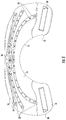
- the alternative body portions 412 a , 412 b can be substantially the same as the body portions 312 a, 312 b but can include openings 422 a, 422 b disposed longitudinally therethrough. Such openings can advantageously reduce the weight of the device if a full light array is not required. While the openings 422 a, 422 b are shown extending up and downward, they can extend in any directions. Further, in the illustrated embodiment, the openings are shown having a generally oval shape, though other shapes are considered to be within the scope of the disclosure.
- the lights 426 can be disposed along the ribs 432 a, 432 b. Lights 426 can be similarly arranged on the front body 412 b.
- the present invention provides a unique solution to the problem of providing a device and method for the treatment of truncal acne that overcomes the disadvantages and side effects of oral and topical medications and remedies taught in the prior art.
Landscapes
- Health & Medical Sciences (AREA)
- Biomedical Technology (AREA)
- Life Sciences & Earth Sciences (AREA)
- Engineering & Computer Science (AREA)
- Nuclear Medicine, Radiotherapy & Molecular Imaging (AREA)
- Pathology (AREA)
- Biophysics (AREA)
- Radiology & Medical Imaging (AREA)
- Animal Behavior & Ethology (AREA)
- General Health & Medical Sciences (AREA)
- Public Health (AREA)
- Veterinary Medicine (AREA)
- Radiation-Therapy Devices (AREA)
Abstract
Description
- The present patent document relates generally to devices for the application phototherapy treatments to a patient and more particularly to a phototherapy apparatus for truncal acne and method of treatment.
- Acne vulgaris is a common cutaneous disorder which can affect adolescents and young adults alike. Body, or truncal, acne can present on all portions of a patient's torso including the back and chest. Patients that suffer from this condition can experience significant scarring of the skin which can result in psychological side-effects. Thus, there has been much research into prevention of acne vulgaris and reduction of the resulting scarring.
- Body or truncal acne is currently primarily treated with topical oral medications, which can have harmful side effects, adverse reactions, or other disadvantages. Common treatments may include over-the-counter medications applied on the skin, such as benzoyl peroxide; prescription acne medications applied on the skin, such as topical retinoids and antibiotics; and oral prescription medications, such as oral antibiotics, isotretinoin, and oral contraceptives.
- There are also a number of homeopathic remedies, such as applying to the affected area one or more of a paste of baking soda, diluted apple cider vinegar applied with a spray bottle, lemon juice applied by a halved lemon, a mixture of honey and oats, or aloe vera. However, these home remedies are messy and often require repeated applications two-three times daily.
- In addition to the topical or oral medications and homeopathic remedies, the prior art has recognized certain benefits of light treatment of truncal acne. Clinician-administered light sources are used for the treatment of acne. Examples of light-based therapies include: broad-spectrum continuous-wave visible light sources (blue light, red light); intense pulsed light; laser sources including the potassium titanyl phosphate (KTP) laser, pulsed dye laser (PDL), and infrared lasers, photodynamic therapy; and photopneumatic technology. Clinician-administered light sources can be complex systems which require extensive training to use. At home light base therapies can suffer from several deficiencies including the need for the user to hold the device in place for the entirety of the light therapy, thereby limiting the user to the use of one free hand—at best. However, light-based treatments are safe, effective, and have minimal complication when used correctly.
- Furthermore, acne on large areas of the body or hard-to-reach spots, such as the back, may make it difficult to apply topical acne medications and/or remedies. Some topical acne treatments may also discolor or bleach clothing. Left untreated, though, truncal acne may lead to a type of scarring called follicular macular atrophy.
- As a result, there is a further need to prevent and treat scarring, including follicular macular atrophy. Current treatments include traditional ablative laser resurfacing, non-ablative fractional laser resurfacing, other collagen remodeling procedures, ablative fractional laser resurfacing, chemical peels, dermabrasion, skin needling, fractional bipolar radiofrequency, and combinations thereof.
- As noted above, there are major challenges when treating truncal acne vulgaris involves extensive body surface area. This factor may complicate treatment with topical therapy. Certain vehicles, such as foams, lotions, and some water-based gels, may be more applicable for truncal application, provided the specific formulation exhibits ease of spreadability, rapid cutaneous penetration, effective drug delivery, and lack of residue. Moreover, scarring is not an uncommon consequence of truncal acne vulgaris. Although scarring is more likely to occur after resolution of deep inflammatory (nodular) acne lesions, scarring may occur in association with acne lesions of any type or severity. A form of acne scarring that occurs almost exclusively on the trunk and upper arms is follicular macular atrophy. Many patients with scarring related to truncal acne vulgaris are bothered by the appearance of this form of atrophic scarring. Unfortunately, a consistently effective treatment regimen for truncal acne scarring is not available. Further, at home management of truncal acne can be mechanically difficult to reach.
- Thus, there is a need for safe and effective therapies for truncal acne and scarring. Therefore, there is a perceived need for a method of treating truncal acne that does not require oral medications, the application of messy topical treatments, or clinician applied treatments.
- The present invention describes methods and apparatuses for applying phototherapy to the body for treating truncal acne that solves the problems of the prior art. The method and apparatus can, for example, be used to treat acne on the back, chest, or both.
- In one exemplary embodiment, the phototherapy methods and apparatuses can include a body portion having a bottom surface and a top surface that is configured to hang on a person's shoulders and cover the upper back or chest. The body portion can further have left and right shoulder portions extending forwardly from the body portion and curled downwardly to hook over a person's shoulders. The left and right shoulder portions can further define a space for a person's neck therebetween. A lighting component can be configured and arranged to emit a light from the bottom surface of the body portion and forwardly extending left and right shoulder portions. In one exemplary method of use, the user can place the left and right shoulder portions on their shoulders with the body portion hanging downwardly against the person's back, wearing the body portion like a cape. In an alternative, the user can place the apparatus on their body such that the body portion covers their chest, wearing apparatus like a bib. In a further alternative, the apparatus can include body portions that can cover both the back and chest of the user at the same time. The apparatus may further include standoffs on the bottom surface of the body and shoulder portions, to elevate the bottom surface, and thus the lights, away from the user's skin. Consequently, the light emitted from the lighting component covers a wider area of the user's trunk.
- Using the lighting component, a therapeutic amount of light can be administered to the user with the apparatus. The administered light can preferably be non-UV light, but may be any therapeutic light, including those discussed above, that is suitable for treating acne or scarring. The administered light may be for any period of time, for example, twenty to thirty minutes, during weekly intervals, or other treatment regimens as determined by the treatment regimen, such as by a medical professional.
- These and other features, aspects, and advantages of the present invention will become better understood with reference to the following description, appended claims, and accompanying drawings where:
-
FIG. 1 is a front perspective view of an exemplary embodiment of the phototherapy apparatus; -
FIG. 2 is a front elevational view of an exemplary embodiment of the phototherapy apparatus; -
FIG. 3 is a rear elevational view of an exemplary embodiment of the phototherapy apparatus; -
FIG. 4 is a rear perspective view of an exemplary embodiment of the phototherapy apparatus; -
FIG. 5 is a bottom view of an exemplary embodiment of the phototherapy apparatus; -
FIG. 6 is a side view of an exemplary embodiment of the phototherapy apparatus; -
FIG. 7A is a side view of an exemplary environment with the apparatus in place on a person; -
FIG. 7B is a side view of an exemplary environment with the apparatus in place on a person in an alternative orientation; -
FIG. 8 is a perspective view of an alternative exemplary embodiment; -
FIGS. 9a-c show various views of a further exemplary embodiment; -
FIG. 10 is a perspective view of an alternative light source; -
FIG. 11 is a diagram illustrating a controller for apparatus; -
FIG. 12 is a flowchart of a method of treatment of truncal acne using the phototherapy apparatus of the present invention; -
FIG. 13 is a perspective view of yet another alternative exemplary embodiment; -
FIG. 14a is a perspective view of a further alternative exemplary embodiment; and -
FIG. 14b is a perspective view of the apparatus ofFIG. 14a in place on a person. - Referring to
FIGS. 1-7 , an exemplary embodiment of a phototherapy apparatus for the treatment of truncal acne is illustrated generally at 10. The apparatus generally includes abody portion 12 having abottom surface 14 and atop surface 16 that is configured to hang on a person's shoulders and cover the upper back. The body portion is preferably made of molded of plastic but may be formed in any way of any type of material, such as thermoformed or three-dimensionally printed plastic or other materials. Thebody portion 12 may also be made of metal and can be cast or press-formed by way of example. - The
body portion 12 further has left andright shoulder portions 18 extending forwardly from thebody portion 12 and curled downwardly to hook over a person's shoulders. The left andright shoulder portions 18 further define a space for a receiving a person's neck therebetween. Thebottom surface 14 of thebody 12 andshoulder portions 18 can be contoured to conform to a person's anatomy.FIG. 7A shows theapparatus 10 installed on a person for use. In some embodiments, as shown inFIGS. 9A-C , a clasp, or tie, 19′ may be provided to “bridge” theshoulder portions 18′ together to retain thedevice 10′ on the user. Theclasp 19′ can be any suitable device such as a hook and loop fastener, snaps, buttons, adhesives, buckles, belts, hooks, or other mechanical fasteners. - In an alternative embodiment, as shown in
FIG. 8 , thebottom edge 12 b″ of thebody 12″ can extend further downward such that a larger portion of the user's back, or front, can be treated with light, as will be discussed above. In a further alternative, the bottom surface can be higher up, if only a small area requires treatment. - A
lighting component 20 is configured and arranged to emit a light from thebottom surface 14 of thebody portion 12 and forwardly extending left andright shoulder portions 18. In use, as seen inFIG. 7 , the person places the left andright shoulder portions 18 on their shoulders with thebody portion 12 hanging downwardly against the person's back, wearing thebody portion 12 like a cape. Alternatively, theapparatus 10 can be worn with the left andright shoulder portions 18 on their shoulders with thebody portion 12 hanging downwardly against the person's chest, wearing thebody portion 12 like a bib, as shown inFIG. 7B . - The
apparatus 10 may include one ormore grooves 21 on thetop surface 16 of body portion, as best seen inFIGS. 3, 4 and 6 . Thegrooves 21 may extend laterally in a trough-like manner on thebody portion 12 and extend onto theshoulder portions 18. On thebottom surface 14 of thebody portion 12, thegrooves 21 may appear asprojections 22. Eachgroove 21 preferably includes one ormore apertures 24. In particular, theapertures 24 pass through the floor of the trough-like grooves 20. Residing within eachgroove 21 are one ormore lighting elements 26 configured to emit light through theapertures 24 of thegrooves 21 and out thebottom surface 14 of the body andshoulder portions grooves 20 may be mirrored to help direct light through theapertures 24 to the user. Together, thelighting elements 26 form thelighting component 20. Thelighting elements 26 and the depth of thegrooves 21 are configured so that the lighting elements reside fully within the grooves so that the rear surface of the apparatus is substantially flush or flat for a clean and aesthetically pleasing appearance. This facilitates the finishing of the product as will be discussed in detail below. - In some embodiments, the
lighting elements 26 may be a plurality of light emitting diodes (LEDs) mounted on a flexible strip and electrically connected together. Themultiple lighting elements 26, such as those indifferent grooves 21, may be further interconnected together viawires 28, as seen inFIG. 3 . To operate thelighting component 20, thelighting elements 26 are connected to apower source 30, such asbatteries 32 or apower supply 34. The batteries orbattery pack 32 orpower supply 34 by be internal or external to thebody portion 12. In some embodiments, acontroller 46 may be connected between thelighting elements 26 andpower source 30, as described further below and seen inFIG. 3 , for example. In some embodiments, thelighting elements 26 of thelighting component 20 are configured to emit non-UV light. In some embodiments, thelighting elements 26 of the are lightingcomponent 20 are preferably configured to emit blue light in wavelengths between about 380 to about 500 nm, for example. - In an alternative embodiment shown in
FIGS. 9a -9 c, thelighting element 26′ can be in the form of a plurality ofpanels 26 a′, 26 b′. While thepanels 26 a′ are shown in a triangular shape, they can have any shape. Similarly, thepanels 26 b′ are shown in a generally rectangular shape, though that can have any shape. Thepanels 26 a′, 26 b′ may be flush with thebottom surface 14′, or alternatively, they can be disposed in trenches (not shown) similar to thegrooves 21 as shown inFIGS. 1-7 . In the alternative embodiment that includes trenches, the trenches can have trough-like grooves to receive thepanels 26 a′, 26 b′, can be mirrored, and can include various apertures to allow light out. Alternatively, the panels can be disposed on thetop surface 16′ of thebody 12′ and thebody 12′ can be semi or fully transparent or opaque to permit certain wavelengths of light therethrough. In some embodiments, thebody 12′ can be made from a soft or flexible material. The panels may provide for a larger concentration of light if needed for a given treatment plan. In a further alternative, shown inFIG. 10 , thelighting element 26″ can be in the form of asheet 26 a″ of LEDs which can be disposed on the interior, or exterior, surface. Such asheet 26 a″ can cover the entirety of the body of the device to provide an even higher intensity, or concentration of light. - The
apparatus 10 also preferably includes one ormore standoffs bottom surface 14 of thebody portion 12 andshoulder portions 18. Thestandoffs bottom surface 14 of thebody portion 12 away from the person wearing theapparatus 10, as best seen inFIG. 7A , thereby allowing light emitted from thelighting component 20 to cover a larger area of the person's skin. In some embodiments, thestandoffs top surface 16 of thebody portion 12 andshoulder portions 18. In some embodiments, therecess 40 on thebody portion 12 may be used to holdbatteries 32 or thepower supply 34 for thelighting component 20, best seen inFIG. 4 . - The
body portion 12 and forwardly extendingshoulder portions 18 may be unitarily molded as a single piece. - As seen in
FIG. 7A , theapparatus 10 preferably includes anouter covering 44, enclosing theapparatus 10 to hide the internal components and make it a more visually appealing finished product. The covering 44 may be made of fabric or layers of fabric and padding. The portion of the covering 44 that covers thebottom surface 14 of thebody portion 12 may include either a window around theapertures 20 for thelighting elements 26 of thelighting component 20 or allow light to transmit through from the lighting component. - Referring to
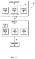
FIG. 11 , a diagram illustrating an embodiment of thephototherapy apparatus 10 is shown generally at 100, that further includes acontroller 46. Thecontroller 46 controls power from thepower source 30 to thelighting elements 26 of thelighting component 20. Thecontroller 46 may include aswitch 48 to control whether thelighting component 20 is on or off. Thecontroller 46 may further include anintensity control 50 configured to control the brightness or lumen output of thelighting elements 26 of thelighting component 20. For example, theintensity control 50 may adjust the lumen output, variably or in stepped increments, between 1,000 and 20,000 lumens. Thecontroller 46 may also include ahue control 52 to control the wavelength or wavelengths of light emitted by thelighting elements 26 of thelighting component 20. For instance, thehue control 52 may adjust thelighting elements 26 to emit blue light in a wavelength of 420 nm, by way of example and not limitation. Thecontroller 46 may also include atimer control 54 configured to operate thelighting elements 26 of thelighting component 20 for a selected or predetermined time and then shut off thelighting elements 26, such as presets in five, ten, fifteen, twenty, twenty-five and/or thirty minute increments, or anywhere from zero to sixty minutes, by way of example and not limitation. It should be noted that thecontroller 46 may be integrated with thelighting component 20 and/orpower source 30. Moreover, any associated variables of the light source can be modified or changes as a particular patient's therapy requires. For example, thecontroller 46 can additionally control the light wavelength, pulse duration, pulse frequency, light fluence, and light irradiance. The controller can be handheld or integrated into thedevice 10 itself. In a further alternative, thecontroller 46 can include local memory to record the number of sessions and the type of session performed so that the data can be reviewed at a later date. Further, thecontroller 46 can include wired or wireless connections to an external computer, tablet, or smart phone to access data and controls remotely. The foregoing is an example of how the delivery of light to the user of theapparatus 10 can be controlled, though it may be modified as desired. - Referring to
FIG. 12 , a flowchart illustrating a method of treatment using theapparatus 10 is illustrated generally at 200. In afirst step 202, the user (or patient) is provided with an embodiment of theapparatus 10 as described generally herein. In asecond step 204, the user (or patient) places theapparatus 10 on a patient where the left andright shoulder portions 18 are on the patient's shoulders with thebody portion 12 against the patient's back, such that the patient is wearing thebody portion 12 like a cape. In analternative step 204, thebody portion 12 can be placed over the chest of the patient to treat the chest area. In thealternative step 204, as shown inFIG. 7B , thebody portions 12 can placed on the patient such that the patient is wearing the body portion like a bib. In athird step 206, the user (or patient) administers a therapeutic amount of light to truncal areas of the patient with thelighting component 20 of theapparatus 10. As used above “user” may refer to a medical professional, such as a medical technician, clinician, nurse, nurse practitioner, physicians' assistant, dermatologist and/or physician, by way of example. Other “users” may include licensed and unlicensed salon operators and others authorized to apply phototherapy treatments, including the patient themselves. - During the
administration step 206, a therapeutic amount of light for about twenty to about thirty minutes may be administered. Furthermore, this process may be repeated at intervals, such as daily, weekly, biweekly and/or monthly, as determined by the treatment regimen. - The step of administering a therapeutic amount of
light 206, may further include selecting a desired light intensity and wavelength with thecontroller 46, via the intensity and hue controls 50, 52. The intensity and hue controls can include certain presets which can correspond to a prescribed light type and light intensity that would be required to treat the particular ailment that the patient is suffering from. In some alternative embodiments, the light source may include a plurality of light sources (not shown) each of varying wavelengths. The controls can be programed to turn on one or more of the plurality of light sources to treat particular skin ailments as needed. - In an alternative embodiment of a device, as shown in
FIG. 13 , a two-sided body device 300 can be provided. In the illustrated embodiment, two fullpanel body portions body portion 12 of the embodiment ofFIG. 1 . Bothbody portions body portions front body 312 a can be longer theback body 312 b, or vice versa. The front andback body portions shoulder portions 318. The two-sided device 300 may, or may not, include stand-offs (not shown) or any of the alternative light sources (not shown). A controller can additionally be included to independently control the light sources disposed on the front andback body portions - In a further alternative, as shown in
FIGS. 14a and 14b , an alternative two-sided body device 400 can be provided. Thealternative body portions body portions openings openings openings back bodies lights 426 can be disposed along theribs Lights 426 can be similarly arranged on thefront body 412 b. - Therefore, it can be seen that the present invention provides a unique solution to the problem of providing a device and method for the treatment of truncal acne that overcomes the disadvantages and side effects of oral and topical medications and remedies taught in the prior art.
- It would be appreciated by those skilled in the art that various changes and modifications can be made to the illustrated embodiments without departing from the spirit of the present invention. All such modifications and changes are intended to be within the scope of the present invention except as limited by the scope of the appended claims.
Claims (11)
Priority Applications (1)
| Application Number | Priority Date | Filing Date | Title |
|---|---|---|---|
| US16/116,518 US10967197B2 (en) | 2018-08-29 | 2018-08-29 | Phototherapy devices and methods for treating truncal acne and scars |
Applications Claiming Priority (1)
| Application Number | Priority Date | Filing Date | Title |
|---|---|---|---|
| US16/116,518 US10967197B2 (en) | 2018-08-29 | 2018-08-29 | Phototherapy devices and methods for treating truncal acne and scars |
Publications (2)
| Publication Number | Publication Date |
|---|---|
| US20200069964A1 true US20200069964A1 (en) | 2020-03-05 |
| US10967197B2 US10967197B2 (en) | 2021-04-06 |
Family
ID=69640808
Family Applications (1)
| Application Number | Title | Priority Date | Filing Date |
|---|---|---|---|
| US16/116,518 Active 2038-09-27 US10967197B2 (en) | 2018-08-29 | 2018-08-29 | Phototherapy devices and methods for treating truncal acne and scars |
Country Status (1)
| Country | Link |
|---|---|
| US (1) | US10967197B2 (en) |
Cited By (2)
| Publication number | Priority date | Publication date | Assignee | Title |
|---|---|---|---|---|
| CN118340987A (en) * | 2024-05-27 | 2024-07-16 | 中山大学孙逸仙纪念医院 | An acne treatment system |
| USD1060695S1 (en) * | 2022-06-10 | 2025-02-04 | Basolite Ltd | Phototherapy device |
Family Cites Families (73)
| Publication number | Priority date | Publication date | Assignee | Title |
|---|---|---|---|---|
| US5616140A (en) * | 1994-03-21 | 1997-04-01 | Prescott; Marvin | Method and apparatus for therapeutic laser treatment |
| US7229436B2 (en) | 1996-01-05 | 2007-06-12 | Thermage, Inc. | Method and kit for treatment of tissue |
| DE69940738D1 (en) | 1998-07-09 | 2009-05-28 | Curelight Medical Ltd | DEVICE AND METHOD FOR EFFICIENT HIGHERGETIC PHOTODYNAMIC THERAPY OF ACNE VULGARIS AND SEBORRHOE |
| US6887260B1 (en) | 1998-11-30 | 2005-05-03 | Light Bioscience, Llc | Method and apparatus for acne treatment |
| US6183773B1 (en) | 1999-01-04 | 2001-02-06 | The General Hospital Corporation | Targeting of sebaceous follicles as a treatment of sebaceous gland disorders |
| US20040122492A1 (en) | 1999-07-07 | 2004-06-24 | Yoram Harth | Phototherapeutic treatment of skin conditions |
| US6290713B1 (en) | 1999-08-24 | 2001-09-18 | Thomas A. Russell | Flexible illuminators for phototherapy |
| WO2002013788A1 (en) | 2000-08-16 | 2002-02-21 | The General Hospital Corporation D/B/A Massachusetts General Hospital | Topical aminolevulinic acid-photodynamic therapy for acne vulgaris |
| US7018396B2 (en) | 2001-08-07 | 2006-03-28 | New England Medical Center Hospitals, Inc. | Method of treating acne |
| US7001413B2 (en) * | 2002-07-03 | 2006-02-21 | Life Support Technologies, Inc. | Methods and apparatus for light therapy |
| US9211259B2 (en) | 2002-11-29 | 2015-12-15 | Foamix Pharmaceuticals Ltd. | Antibiotic kit and composition and uses thereof |
| US8709003B2 (en) | 2003-02-25 | 2014-04-29 | Tria Beauty, Inc. | Capacitive sensing method and device for detecting skin |
| JP4361081B2 (en) | 2003-02-25 | 2009-11-11 | トリア ビューティ インコーポレイテッド | Eye-safe dermatological treatment device |
| JP4361082B2 (en) | 2003-02-25 | 2009-11-11 | トリア ビューティ インコーポレイテッド | Built-in diode laser dermatological treatment device |
| US7413567B2 (en) | 2003-02-25 | 2008-08-19 | Spectragenics, Inc. | Optical sensor and method for identifying the presence of skin |
| US20100069898A1 (en) | 2003-02-25 | 2010-03-18 | Tria Beauty, Inc. | Acne Treatment Method, System and Device |
| ES2570985T3 (en) | 2003-02-25 | 2016-05-23 | Tria Beauty Inc | Apparatus and procedure for inhibiting new hair growth, safe for the eye and autonomous |
| US8777935B2 (en) | 2004-02-25 | 2014-07-15 | Tria Beauty, Inc. | Optical sensor and method for identifying the presence of skin |
| US20060030908A1 (en) | 2004-08-09 | 2006-02-09 | Lumiport, Llc | Skin treatment phototherapy device |
| US20080269730A1 (en) * | 2005-04-14 | 2008-10-30 | Dotson Robert S | Ophthalmic Phototherapy Device and Associated Treatment Method |
| US20090306023A1 (en) | 2005-06-29 | 2009-12-10 | Ramirez Jose E | Stable organic peroxide compositions |
| US7556820B2 (en) | 2005-06-29 | 2009-07-07 | Jr Chem, Llc | Stable organic peroxide compositions |
| GB0515550D0 (en) | 2005-07-29 | 2005-09-07 | Univ Strathclyde | Inactivation of staphylococcus species |
| EP2043685B1 (en) | 2006-07-03 | 2015-12-23 | Genmab A/S | Prevention of rash in patients undergoing anti-egfr therapy |
| US8337809B2 (en) | 2006-09-11 | 2012-12-25 | William Marsh Rice University | Charge-assembled capsules for phototherapy |
| US20080260655A1 (en) | 2006-11-14 | 2008-10-23 | Dov Tamarkin | Substantially non-aqueous foamable petrolatum based pharmaceutical and cosmetic compositions and their uses |
| US20090004161A1 (en) | 2007-06-26 | 2009-01-01 | Palladino Linda O | Methods for treating pustular conditions of the skin |
| US9079022B2 (en) | 2007-09-27 | 2015-07-14 | Led Intellectual Properties, Llc | LED based phototherapy device for photo-rejuvenation of cells |
| KR100944895B1 (en) | 2007-10-09 | 2010-03-03 | 한국전기연구원 | Combined Light Source Device for Phototherapy |
| JP2011509791A (en) | 2008-01-24 | 2011-03-31 | シネロン メディカル リミテッド | Apparatus, device and method for adipose tissue treatment |
| US8206326B2 (en) | 2008-03-04 | 2012-06-26 | Sound Surgical Technologies, Llc | Combination ultrasound-phototherapy transducer |
| US20150217142A1 (en) | 2008-03-04 | 2015-08-06 | Photosonix Medical, Inc. | Method and device for treatment with combination ultrasound-phototherapy transducer |
| US9314293B2 (en) | 2008-07-16 | 2016-04-19 | Syneron Medical Ltd | RF electrode for aesthetic and body shaping devices and method of using same |
| US20100017750A1 (en) | 2008-07-16 | 2010-01-21 | Avner Rosenberg | User interface |
| KR101083061B1 (en) | 2009-05-07 | 2011-11-16 | 전남대학교산학협력단 | Portable skin light therapy device |
| EP3205355A1 (en) | 2008-11-07 | 2017-08-16 | KLOX Technologies, Inc. | Combination of an oxidant and a photoactivator |
| EP2401026B1 (en) | 2009-02-25 | 2014-04-02 | Syneron Medical Ltd. | Electrical skin rejuvenation |
| WO2011067761A1 (en) | 2009-12-06 | 2011-06-09 | Syneron Medical Ltd. | A method and apparatus for personal skin treatment |
| CN101862507B (en) | 2010-06-24 | 2013-04-24 | 上海市激光技术研究所 | High-power purple-green-red LED light diagnosis and treatment instrument |
| WO2012027728A2 (en) | 2010-08-27 | 2012-03-01 | Sienna Labs, Inc. | Compositions and methods for targeted thermomodulation |
| US9572880B2 (en) | 2010-08-27 | 2017-02-21 | Sienna Biopharmaceuticals, Inc. | Ultrasound delivery of nanoparticles |
| US10272257B2 (en) | 2011-09-08 | 2019-04-30 | Johnson & Johnson Consumer, Inc. | Light therapy platform inductive mask and charger |
| US10213618B2 (en) | 2011-09-08 | 2019-02-26 | Johnson & Johnson Consumer, Inc. | Light therapy platform combination mask |
| US8771328B2 (en) | 2011-09-08 | 2014-07-08 | La Lumiere Llc | Light therapy platform system |
| DE102011117364A1 (en) | 2011-10-29 | 2013-05-02 | Merck Patent Gmbh | Skin whitening in phototherapy |
| US10111821B2 (en) | 2011-11-03 | 2018-10-30 | Applied Biology, Inc. | Methods and compositions for administering a specific wavelength phototherapy |
| US20130281913A1 (en) | 2012-04-20 | 2013-10-24 | Klox Technologies Inc. | Biophotonic compositions and methods for providing biophotonic treatment |
| BR102012019268A2 (en) | 2012-08-01 | 2016-03-01 | Álvaro Pereira De Oliveira | led light phototherapy equipment |
| RU2646809C2 (en) | 2012-10-11 | 2018-03-07 | Нанокомпозикс, Инк. | Silver nanoplates compositions and methods |
| US8784462B2 (en) * | 2012-11-30 | 2014-07-22 | Richard Ogden Deroberts | Flexible, wearable therapeutic laser array |
| CN103945151A (en) | 2013-01-23 | 2014-07-23 | 唐君 | LED television with optical physiotherapy and health care functions |
| CN103933667A (en) | 2013-01-23 | 2014-07-23 | 唐君 | Mobile phone with optical physiotherapy and health care functions |
| CN203072062U (en) | 2013-01-23 | 2013-07-17 | 唐君 | OLED television with functions of optical physiotherapy and health care |
| CN203072061U (en) | 2013-01-23 | 2013-07-17 | 唐君 | LED liquid crystal television with functions of optical physiotherapy and health care |
| CN103945150A (en) | 2013-01-23 | 2014-07-23 | 唐君 | LED liquid crystal television with optical physiotherapy and health care functions |
| BR112015020804A2 (en) | 2013-03-01 | 2017-07-18 | Klox Tech Inc | phototherapeutic device, method and use |
| US20140276354A1 (en) | 2013-03-14 | 2014-09-18 | Klox Technologies Inc. | Biophotonic materials and uses thereof |
| EP2973751A4 (en) | 2013-03-15 | 2016-11-16 | Gary Wayne Jones | AMBIAN LIGHT SPECTRUM CONVERSION DEVICE |
| WO2014146029A1 (en) | 2013-03-15 | 2014-09-18 | Jones Gary W | Multispectral therapeutic light source |
| US20140323331A1 (en) | 2013-04-26 | 2014-10-30 | Dermtech International | Biomarkers for diagnosis and treatment of acne vulgaris |
| EP3036003A1 (en) | 2013-08-22 | 2016-06-29 | Merck Patent GmbH | Diffusion pigments in phototherapy |
| EP2905544A1 (en) | 2014-02-10 | 2015-08-12 | Electrolux Appliances Aktiebolag | Kitchen hood for phototherapy comprising a high illuminance light source |
| US20160016001A1 (en) | 2014-02-28 | 2016-01-21 | Klox Technologies Inc. | Phototherapeutic device, method and use |
| JP2017524398A (en) | 2014-06-04 | 2017-08-31 | クロクス テクノロジーズ インコーポレイテッド | Biophoto hydrogel |
| US11266685B2 (en) | 2014-06-09 | 2022-03-08 | Klox Technologies Inc. | Silicone-based biophotonic compositions and uses thereof |
| AR100864A1 (en) | 2014-06-09 | 2016-11-09 | Klox Tech Inc | THERMOENDURECIBLE BIOPHOTONIC COMPOSITIONS AND THEIR USES |
| CN106714843A (en) | 2014-06-24 | 2017-05-24 | 克洛克斯科技公司 | Biophotonic compositions comprising halogen and uses thereof |
| CN105534634A (en) | 2014-10-27 | 2016-05-04 | 深圳市伦琴科技有限公司 | Child and adult double-mode thermal therapy, light therapy and magnetic therapy skin physiotherapeutic instrument |
| AU2015358910B2 (en) | 2014-12-12 | 2019-01-24 | Dermavant Sciences GmbH | Novel method of use |
| US20170014640A1 (en) * | 2014-12-29 | 2017-01-19 | Abijith Kariguddaiah | Portable, HANDS-FREE, PRE-CALIBRATED and WEARABLE Laser brace/wrap type clinical-strength medical device/apparatus, with embedded Low-Level-Laser-Therapy (LLLT), providing for a new method/modality for Pain relief in the form of orthopedic LASERWRAPS, from joint related musculoskeletal pain caused by joint related illnesses including - TENNIS ELBOW, CARPEL-TUNNEL, ARTHRITIS, OSTEOPEROSIS, PLANTAR FASCITIS, TENDONITIS (BACK PAIN, KNEE TENDONITIS, HAND TENDONITIS, ACHILLES TENDONITIS), SPORT INJURIES & BURSITIS |
| EP3271012B1 (en) | 2015-03-17 | 2019-06-19 | Inderm | Devices for providing skin care using phototherapy |
| WO2016168385A2 (en) | 2015-04-14 | 2016-10-20 | Photosonix Medical, Inc. | Method and device for treatment with combination ultrasound-phototherapy transducer |
| CA2973009A1 (en) * | 2016-07-13 | 2018-01-13 | Meditech International Inc. | Systems and methods for treating head injury using multi-colour light |
-
2018
- 2018-08-29 US US16/116,518 patent/US10967197B2/en active Active
Cited By (3)
| Publication number | Priority date | Publication date | Assignee | Title |
|---|---|---|---|---|
| USD1060695S1 (en) * | 2022-06-10 | 2025-02-04 | Basolite Ltd | Phototherapy device |
| USD1060696S1 (en) * | 2022-06-10 | 2025-02-04 | Basolite Ltd | Phototherapy device |
| CN118340987A (en) * | 2024-05-27 | 2024-07-16 | 中山大学孙逸仙纪念医院 | An acne treatment system |
Also Published As
| Publication number | Publication date |
|---|---|
| US10967197B2 (en) | 2021-04-06 |
Similar Documents
| Publication | Publication Date | Title |
|---|---|---|
| US8435273B2 (en) | High powered light emitting diode photobiology device | |
| US11975215B2 (en) | Devices and related methods for phototherapeutic treatment of skin | |
| CN203663253U (en) | Beauty and health care face mask and face beauty and health care instrument | |
| US20100331930A1 (en) | Phototherapy device | |
| KR102904923B1 (en) | Biostimulation light irradiation device | |
| US20070282400A1 (en) | Combination medical therapy device that integrates: electrical stimulation, light therapy, heat, pressure, and vibration | |
| KR101225135B1 (en) | Rechargeable patch for color light therapy | |
| KR101764333B1 (en) | Skin care device with neck massage | |
| KR20190099371A (en) | Skin care and treatment system | |
| US10967197B2 (en) | Phototherapy devices and methods for treating truncal acne and scars | |
| KR20170128147A (en) | Skin care apparatus | |
| US9808314B2 (en) | Fat reducing device and method utilizing optical emitters | |
| WO2018127921A1 (en) | Apparatus and method for skin rejuvenation | |
| JP2012016438A (en) | Apparatus for treating user's skin | |
| JP3126750U (en) | Bowl | |
| KR20080025989A (en) | Infrared hair loss treatment device and hair growth promoting device | |
| US20050192650A1 (en) | Hand-held device for ameliorating skin imperfections using LED light emissions | |
| TWM563195U (en) | Flexible photothermal mask instrument | |
| CN109045483B (en) | Physiotherapy glove device | |
| US20070135869A1 (en) | Apparatus for stimulating acupuncture points on a human face | |
| CN102371031A (en) | Method and device for using light energy to stimulate brain waves | |
| WO2018172757A1 (en) | Phototherapy apparatus | |
| CA2775529C (en) | High powered light emitting diode photobiology device | |
| US20230364440A1 (en) | Battery powered systems for light therapy and related methods | |
| CN219595645U (en) | Ultrasonic atomization thermal therapy cabin |
Legal Events
| Date | Code | Title | Description |
|---|---|---|---|
| AS | Assignment |
Owner name: AZULITE, INC., CONNECTICUT Free format text: ASSIGNMENT OF ASSIGNORS INTEREST;ASSIGNORS:ELTORAI, ADAM E. M.;GERTRUDES, DANIEL;NGUYEN, DON;REEL/FRAME:046743/0968 Effective date: 20180730 |
|
| FEPP | Fee payment procedure |
Free format text: ENTITY STATUS SET TO UNDISCOUNTED (ORIGINAL EVENT CODE: BIG.); ENTITY STATUS OF PATENT OWNER: SMALL ENTITY |
|
| FEPP | Fee payment procedure |
Free format text: ENTITY STATUS SET TO SMALL (ORIGINAL EVENT CODE: SMAL); ENTITY STATUS OF PATENT OWNER: SMALL ENTITY |
|
| STPP | Information on status: patent application and granting procedure in general |
Free format text: RESPONSE TO NON-FINAL OFFICE ACTION ENTERED AND FORWARDED TO EXAMINER |
|
| STPP | Information on status: patent application and granting procedure in general |
Free format text: FINAL REJECTION MAILED |
|
| STPP | Information on status: patent application and granting procedure in general |
Free format text: DOCKETED NEW CASE - READY FOR EXAMINATION |
|
| STPP | Information on status: patent application and granting procedure in general |
Free format text: PUBLICATIONS -- ISSUE FEE PAYMENT VERIFIED |
|
| STCF | Information on status: patent grant |
Free format text: PATENTED CASE |
|
| MAFP | Maintenance fee payment |
Free format text: PAYMENT OF MAINTENANCE FEE, 4TH YR, SMALL ENTITY (ORIGINAL EVENT CODE: M2551); ENTITY STATUS OF PATENT OWNER: SMALL ENTITY Year of fee payment: 4 |