US20190128362A1 - Smart fluid damper - Google Patents
Smart fluid damper Download PDFInfo
- Publication number
- US20190128362A1 US20190128362A1 US15/801,042 US201715801042A US2019128362A1 US 20190128362 A1 US20190128362 A1 US 20190128362A1 US 201715801042 A US201715801042 A US 201715801042A US 2019128362 A1 US2019128362 A1 US 2019128362A1
- Authority
- US
- United States
- Prior art keywords
- fluid
- damper
- field
- flow control
- control element
- Prior art date
- Legal status (The legal status is an assumption and is not a legal conclusion. Google has not performed a legal analysis and makes no representation as to the accuracy of the status listed.)
- Granted
Links
Images


Classifications
-
- F—MECHANICAL ENGINEERING; LIGHTING; HEATING; WEAPONS; BLASTING
- F16—ENGINEERING ELEMENTS AND UNITS; GENERAL MEASURES FOR PRODUCING AND MAINTAINING EFFECTIVE FUNCTIONING OF MACHINES OR INSTALLATIONS; THERMAL INSULATION IN GENERAL
- F16F—SPRINGS; SHOCK-ABSORBERS; MEANS FOR DAMPING VIBRATION
- F16F9/00—Springs, vibration-dampers, shock-absorbers, or similarly-constructed movement-dampers using a fluid or the equivalent as damping medium
- F16F9/32—Details
- F16F9/53—Means for adjusting damping characteristics by varying fluid viscosity, e.g. electromagnetically
- F16F9/535—Magnetorheological [MR] fluid dampers
-
- B—PERFORMING OPERATIONS; TRANSPORTING
- B62—LAND VEHICLES FOR TRAVELLING OTHERWISE THAN ON RAILS
- B62K—CYCLES; CYCLE FRAMES; CYCLE STEERING DEVICES; RIDER-OPERATED TERMINAL CONTROLS SPECIALLY ADAPTED FOR CYCLES; CYCLE AXLE SUSPENSIONS; CYCLE SIDECARS, FORECARS, OR THE LIKE
- B62K25/00—Axle suspensions
- B62K25/04—Axle suspensions for mounting axles resiliently on cycle frame or fork
- B62K25/06—Axle suspensions for mounting axles resiliently on cycle frame or fork with telescopic fork, e.g. including auxiliary rocking arms
- B62K25/08—Axle suspensions for mounting axles resiliently on cycle frame or fork with telescopic fork, e.g. including auxiliary rocking arms for front wheel
-
- B—PERFORMING OPERATIONS; TRANSPORTING
- B62—LAND VEHICLES FOR TRAVELLING OTHERWISE THAN ON RAILS
- B62K—CYCLES; CYCLE FRAMES; CYCLE STEERING DEVICES; RIDER-OPERATED TERMINAL CONTROLS SPECIALLY ADAPTED FOR CYCLES; CYCLE AXLE SUSPENSIONS; CYCLE SIDECARS, FORECARS, OR THE LIKE
- B62K25/00—Axle suspensions
- B62K25/04—Axle suspensions for mounting axles resiliently on cycle frame or fork
- B62K25/06—Axle suspensions for mounting axles resiliently on cycle frame or fork with telescopic fork, e.g. including auxiliary rocking arms
- B62K25/10—Axle suspensions for mounting axles resiliently on cycle frame or fork with telescopic fork, e.g. including auxiliary rocking arms for rear wheel
-
- B—PERFORMING OPERATIONS; TRANSPORTING
- B62—LAND VEHICLES FOR TRAVELLING OTHERWISE THAN ON RAILS
- B62K—CYCLES; CYCLE FRAMES; CYCLE STEERING DEVICES; RIDER-OPERATED TERMINAL CONTROLS SPECIALLY ADAPTED FOR CYCLES; CYCLE AXLE SUSPENSIONS; CYCLE SIDECARS, FORECARS, OR THE LIKE
- B62K25/00—Axle suspensions
- B62K25/04—Axle suspensions for mounting axles resiliently on cycle frame or fork
- B62K25/28—Axle suspensions for mounting axles resiliently on cycle frame or fork with pivoted chain-stay
-
- F—MECHANICAL ENGINEERING; LIGHTING; HEATING; WEAPONS; BLASTING
- F16—ENGINEERING ELEMENTS AND UNITS; GENERAL MEASURES FOR PRODUCING AND MAINTAINING EFFECTIVE FUNCTIONING OF MACHINES OR INSTALLATIONS; THERMAL INSULATION IN GENERAL
- F16F—SPRINGS; SHOCK-ABSORBERS; MEANS FOR DAMPING VIBRATION
- F16F9/00—Springs, vibration-dampers, shock-absorbers, or similarly-constructed movement-dampers using a fluid or the equivalent as damping medium
- F16F9/10—Springs, vibration-dampers, shock-absorbers, or similarly-constructed movement-dampers using a fluid or the equivalent as damping medium using liquid only; using a fluid of which the nature is immaterial
- F16F9/14—Devices with one or more members, e.g. pistons, vanes, moving to and fro in chambers and using throttling effect
- F16F9/16—Devices with one or more members, e.g. pistons, vanes, moving to and fro in chambers and using throttling effect involving only straight-line movement of the effective parts
- F16F9/18—Devices with one or more members, e.g. pistons, vanes, moving to and fro in chambers and using throttling effect involving only straight-line movement of the effective parts with a closed cylinder and a piston separating two or more working spaces therein
- F16F9/19—Devices with one or more members, e.g. pistons, vanes, moving to and fro in chambers and using throttling effect involving only straight-line movement of the effective parts with a closed cylinder and a piston separating two or more working spaces therein with a single cylinder and of single-tube type
-
- F—MECHANICAL ENGINEERING; LIGHTING; HEATING; WEAPONS; BLASTING
- F16—ENGINEERING ELEMENTS AND UNITS; GENERAL MEASURES FOR PRODUCING AND MAINTAINING EFFECTIVE FUNCTIONING OF MACHINES OR INSTALLATIONS; THERMAL INSULATION IN GENERAL
- F16F—SPRINGS; SHOCK-ABSORBERS; MEANS FOR DAMPING VIBRATION
- F16F9/00—Springs, vibration-dampers, shock-absorbers, or similarly-constructed movement-dampers using a fluid or the equivalent as damping medium
- F16F9/32—Details
- F16F9/34—Special valve constructions; Shape or construction of throttling passages
-
- F—MECHANICAL ENGINEERING; LIGHTING; HEATING; WEAPONS; BLASTING
- F16—ENGINEERING ELEMENTS AND UNITS; GENERAL MEASURES FOR PRODUCING AND MAINTAINING EFFECTIVE FUNCTIONING OF MACHINES OR INSTALLATIONS; THERMAL INSULATION IN GENERAL
- F16F—SPRINGS; SHOCK-ABSORBERS; MEANS FOR DAMPING VIBRATION
- F16F9/00—Springs, vibration-dampers, shock-absorbers, or similarly-constructed movement-dampers using a fluid or the equivalent as damping medium
- F16F9/32—Details
- F16F9/53—Means for adjusting damping characteristics by varying fluid viscosity, e.g. electromagnetically
- F16F9/532—Electrorheological [ER] fluid dampers
-
- F—MECHANICAL ENGINEERING; LIGHTING; HEATING; WEAPONS; BLASTING
- F16—ENGINEERING ELEMENTS AND UNITS; GENERAL MEASURES FOR PRODUCING AND MAINTAINING EFFECTIVE FUNCTIONING OF MACHINES OR INSTALLATIONS; THERMAL INSULATION IN GENERAL
- F16F—SPRINGS; SHOCK-ABSORBERS; MEANS FOR DAMPING VIBRATION
- F16F9/00—Springs, vibration-dampers, shock-absorbers, or similarly-constructed movement-dampers using a fluid or the equivalent as damping medium
- F16F9/32—Details
- F16F9/53—Means for adjusting damping characteristics by varying fluid viscosity, e.g. electromagnetically
- F16F9/535—Magnetorheological [MR] fluid dampers
- F16F9/537—Magnetorheological [MR] fluid dampers specially adapted valves therefor
-
- F—MECHANICAL ENGINEERING; LIGHTING; HEATING; WEAPONS; BLASTING
- F16—ENGINEERING ELEMENTS AND UNITS; GENERAL MEASURES FOR PRODUCING AND MAINTAINING EFFECTIVE FUNCTIONING OF MACHINES OR INSTALLATIONS; THERMAL INSULATION IN GENERAL
- F16D—COUPLINGS FOR TRANSMITTING ROTATION; CLUTCHES; BRAKES
- F16D37/00—Clutches in which the drive is transmitted through a medium consisting of small particles, e.g. centrifugally speed-responsive
- F16D37/02—Clutches in which the drive is transmitted through a medium consisting of small particles, e.g. centrifugally speed-responsive the particles being magnetisable
-
- F—MECHANICAL ENGINEERING; LIGHTING; HEATING; WEAPONS; BLASTING
- F16—ENGINEERING ELEMENTS AND UNITS; GENERAL MEASURES FOR PRODUCING AND MAINTAINING EFFECTIVE FUNCTIONING OF MACHINES OR INSTALLATIONS; THERMAL INSULATION IN GENERAL
- F16F—SPRINGS; SHOCK-ABSORBERS; MEANS FOR DAMPING VIBRATION
- F16F2222/00—Special physical effects, e.g. nature of damping effects
- F16F2222/06—Magnetic or electromagnetic
-
- F—MECHANICAL ENGINEERING; LIGHTING; HEATING; WEAPONS; BLASTING
- F16—ENGINEERING ELEMENTS AND UNITS; GENERAL MEASURES FOR PRODUCING AND MAINTAINING EFFECTIVE FUNCTIONING OF MACHINES OR INSTALLATIONS; THERMAL INSULATION IN GENERAL
- F16F—SPRINGS; SHOCK-ABSORBERS; MEANS FOR DAMPING VIBRATION
- F16F2222/00—Special physical effects, e.g. nature of damping effects
- F16F2222/12—Fluid damping
-
- F—MECHANICAL ENGINEERING; LIGHTING; HEATING; WEAPONS; BLASTING
- F16—ENGINEERING ELEMENTS AND UNITS; GENERAL MEASURES FOR PRODUCING AND MAINTAINING EFFECTIVE FUNCTIONING OF MACHINES OR INSTALLATIONS; THERMAL INSULATION IN GENERAL
- F16F—SPRINGS; SHOCK-ABSORBERS; MEANS FOR DAMPING VIBRATION
- F16F2224/00—Materials; Material properties
- F16F2224/02—Materials; Material properties solids
- F16F2224/0208—Alloys
-
- F—MECHANICAL ENGINEERING; LIGHTING; HEATING; WEAPONS; BLASTING
- F16—ENGINEERING ELEMENTS AND UNITS; GENERAL MEASURES FOR PRODUCING AND MAINTAINING EFFECTIVE FUNCTIONING OF MACHINES OR INSTALLATIONS; THERMAL INSULATION IN GENERAL
- F16F—SPRINGS; SHOCK-ABSORBERS; MEANS FOR DAMPING VIBRATION
- F16F2224/00—Materials; Material properties
- F16F2224/04—Fluids
- F16F2224/043—Fluids electrorheological
-
- F—MECHANICAL ENGINEERING; LIGHTING; HEATING; WEAPONS; BLASTING
- F16—ENGINEERING ELEMENTS AND UNITS; GENERAL MEASURES FOR PRODUCING AND MAINTAINING EFFECTIVE FUNCTIONING OF MACHINES OR INSTALLATIONS; THERMAL INSULATION IN GENERAL
- F16F—SPRINGS; SHOCK-ABSORBERS; MEANS FOR DAMPING VIBRATION
- F16F2224/00—Materials; Material properties
- F16F2224/04—Fluids
- F16F2224/045—Fluids magnetorheological
-
- F—MECHANICAL ENGINEERING; LIGHTING; HEATING; WEAPONS; BLASTING
- F16—ENGINEERING ELEMENTS AND UNITS; GENERAL MEASURES FOR PRODUCING AND MAINTAINING EFFECTIVE FUNCTIONING OF MACHINES OR INSTALLATIONS; THERMAL INSULATION IN GENERAL
- F16F—SPRINGS; SHOCK-ABSORBERS; MEANS FOR DAMPING VIBRATION
- F16F2228/00—Functional characteristics, e.g. variability, frequency-dependence
- F16F2228/06—Stiffness
- F16F2228/066—Variable stiffness
-
- F—MECHANICAL ENGINEERING; LIGHTING; HEATING; WEAPONS; BLASTING
- F16—ENGINEERING ELEMENTS AND UNITS; GENERAL MEASURES FOR PRODUCING AND MAINTAINING EFFECTIVE FUNCTIONING OF MACHINES OR INSTALLATIONS; THERMAL INSULATION IN GENERAL
- F16F—SPRINGS; SHOCK-ABSORBERS; MEANS FOR DAMPING VIBRATION
- F16F9/00—Springs, vibration-dampers, shock-absorbers, or similarly-constructed movement-dampers using a fluid or the equivalent as damping medium
- F16F9/02—Springs, vibration-dampers, shock-absorbers, or similarly-constructed movement-dampers using a fluid or the equivalent as damping medium using gas only or vacuum
- F16F9/0209—Telescopic
- F16F9/0281—Details
-
- G—PHYSICS
- G05—CONTROLLING; REGULATING
- G05G—CONTROL DEVICES OR SYSTEMS INSOFAR AS CHARACTERISED BY MECHANICAL FEATURES ONLY
- G05G5/00—Means for preventing, limiting or returning the movements of parts of a control mechanism, e.g. locking controlling member
- G05G5/03—Means for enhancing the operator's awareness of arrival of the controlling member at a command or datum position; Providing feel, e.g. means for creating a counterforce
Definitions
- the application relates generally to vibration damping mechanisms and, more particularly, to a smart fluid damper.
- So-called “smart” fluids such as magnetorheological (MR) fluids and electrorheological (ER) fluids, are fluids that have one or more properties that can change when a given external field is applied thereto.
- Such external fields may include, for example, a magnetic field in the case of MR fluids and an electric field in the case of ER fluids.
- the variable properties of such smart fluids may include, for example, viscosity, surface tension, yield stress point, and the like.
- an applied magnetic field acts to manipulate the MR fluid, which has micron-sized ferromagnetic particles in a carrier liquid, such as silicone or hydrocarbon oil. Apparent viscosity of the MR fluid can accordingly be varied and thus controlled.
- MR fluid dampers as “controllable” shock absorbers that are capable of attenuating vibrations and/or motion to variable degrees by manipulating the MF fluid within the shock absorber, and thus the damping factor of the shock absorber.
- the shock absorber can thus be made “softer” or “stiffer”, as required, by controlling the strength of the magnetic field to which the MR fluid in the shock absorber is subjected. More specifically, this manipulation of the MR fluid occurs because the ferromagnetic particles in the MR fluid align along the lines of magnetic flux to form chains within the fluid, when the fluid is exposed to a magnetic field. This has the effect of increasing the apparent viscosity of the fluid.
- ER fluid dampers operate in a similar manner, except that the field to which the ER fluid within the damper is applied is an electric field, the strength of which can be controlled as desired to increase or decrease the stiffness of the ER fluid damper.
- the MR fluid used in known MR dampers is however typically much denser and heavier than a conventional hydraulic fluid, due to the presence of the ferromagnetic particles in the MR fluid, which therefore increases the overall weight of the damper. While this weight penalty may not be of significant concern for certain applications where weight is not critical, existing MF dampers are less desirable for use in applications in which the weight of the shock absorber is an important factor. Since MR dampers are difficult to scale down in size and/or weight, their use to date has typically been limited to large-scale applications and/or applications which are not weight sensitive.
- a smart fluid damper comprising: a damper body defining a cavity having a smart fluid stored therein; a piston having a piston head disposed within the cavity of the damper body and slidingly displaceable therein along a piston axis; and a flow control element disposed within the cavity of the damper body, the flow control element including a main body having a central core, an outer housing that surrounds the main body and is spaced apart therefrom to define at least one fluid passage between the main body and the outer housing, the fluid passage extending a complete axial length of the main body to permit fluid flow therethrough from one axial side of the flow control element to the other, the central core including an energizable coil operable to generate a field to the smart fluid in the fluid passage, and a plurality of field barriers each operable to locally block the field generated by the energizable coil such that the field cannot pass therethrough, a first group of the field barriers being mounted to the main body of the flow control element and axially space
- a bicycle comprising: a frame to which a front wheel and a rear wheel are rotatably mounted; and a suspension system disposed between a portion of the frame and at least one of the rear wheel and the front wheel of the bicycle, the suspension system comprising: a smart fluid damper, comprising: a damper body defining a cavity having a smart fluid stored therein; a piston having a piston head disposed within the cavity of the damper body and slidingly displaceable therein along a piston axis; and a flow control element disposed within the cavity of the damper body, the flow control element including a main body having a central core, an outer housing that surrounds the main body and is spaced apart therefrom to define a fluid passage between the main body and the outer housing, the fluid passage extending a complete axial length of the main body to permit fluid flow therethrough from one axial side of the flow control element to the other, the central core including an energizable coil operable to apply a field to the
- a method of dampening a movement with a smart fluid damper comprising using a flow control element disposed within a cavity of the damper to apply a field to the smart fluid within a fluid passage extending through the flow control element, and using a number of field barriers disposed within the flow control element and proximate the fluid passage on either side thereof to locally block the field such that the field cannot pass therethrough, the field barriers arranged to cause the field to criss-cross the fluid passage at multiple axial intervals thereby focusing the field within the fluid passage.
- a magnetorheological (MR) fluid damper comprising a damper body defining therewithin a cavity containing an MR fluid therewithin and a piston having a piston head displaceable within the cavity, and a flow control element disposed within the cavity of the damper body and configured to apply a magnetic field to the MR fluid within a fluid passage axially extending through the flow control element to allow the MR fluid to flow from one side of the flow control element to the other within the cavity, the flow control element having a number of field barriers disposed on either side of the fluid passage, the field barriers operable to locally block and/or divert the magnetic field such that the field cannot pass directly therethrough, the field barriers staggered on either side of the fluid passage to force the magnetic field to criss-cross the fluid passage at multiple axial intervals along the fluid passage thereby focusing the magnetic field within the fluid passage.
- MR magnetorheological
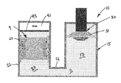
- FIG. 1A is a cross-sectional side view of a smart fluid damper in accordance with an embodiment of the present disclosure, wherein a flow control element of the smart fluid damper is stationary and operates as a valve within the damper;
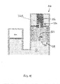
- FIG. 1B is a detailed cross-sectional side view of the flow control element of the smart fluid damper of FIG. 1A ;
- FIG. 2 is a cross-sectional side view of an alternate embodiment of the smart fluid damper of FIG. 1A , having two stationary flow control elements in parallel, each operating as a unidirectional valve;
- FIG. 3A is a cross-sectional side view of a smart fluid damper in accordance with another embodiment of the present disclosure, wherein a flow control element of the smart fluid damper is displaceable and forms part of a piston of the smart fluid damper;
- FIG. 3B is a detailed cross-sectional side view of the flow control element of the smart fluid damper of FIG. 3A ;
- FIG. 4 is a cross-sectional side view of an alternate embodiment of the smart fluid damper of FIG. 3A , having an independent piston with an additional adjustable flow passage;
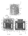
- FIG. 5A is a perspective view of the piston head and flow control element of the smart fluid damper of FIG. 3A ;
- FIG. 5B is a perspective cross-sectional view of the piston head and flow control element of FIG. 5A ;
- FIG. 5C is a side cross-sectional view of the piston head and flow control element of FIG. 5A ;
- FIG. 6A is a perspective view of the smart fluid damper of FIG. 3A ;
- FIG. 6B is a detailed perspective view of the piston of the smart fluid damper of FIG. 6A ;
- FIG. 7A is a perspective view of a part of the smart fluid damper of FIG. 1A ;
- FIG. 7B is a perspective cross-sectional view of the part of the smart fluid damper of FIG. 7A ;
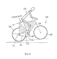
- FIG. 8 is a schematic side elevational view of a bicycle having a smart fluid damper as described herein.
- the smart fluid dampers as described herein are configured to attenuate, absorb, or otherwise lessen the kinetic energy emanating from a source of shock or vibration so that its effect on a component being shielded from the source of shock or vibration is reduced.
- shock absorbers will be used herein with reference to the described devices, such devices are also commonly referred to as “shock absorbers”.
- the present smart fluid dampers provide advantageous force attenuation relative to their size and weight, thereby making them suitable for a wide range of weight and power sensitive applications.
- the present smart fluid dampers examples include, but are not limited to, automobiles, aircraft and other airborne vehicles, robotics, prosthetics, exoskeletons, and human/muscle-powered vehicles such as bicycles.
- the smart fluid dampers as described herein will be principally discussed in connection with their use in the suspension system of a bicycle, it is to be understood that the dampers of the present disclosure can be used in any one or more of the above-noted applications or in other suitable applications, wherein it may be desirable or necessary to provide variable, controlled, damping of vibrations while remaining relative light weight and/or while consuming less power than known MR dampers.
- so-called “smart” fluids as referred to herein are understood to include magnetorheological (MR) fluids and electrorheological (ER) fluids. While the embodiments of the dampers of the present disclosure will now generally be described below with reference to embodiments with MR fluid and MR fluid dampers, it is to be understood that the concepts and features of the MR dampers as described herein, and all of the embodiments described below, can also be adapted for use in ER fluid dampers and other smart fluid vibration dampers. For ease of reference, therefore, the smart fluid dampers of the present disclosure will therefore now be referred to simply as “MR dampers”, which employ MR fluid therein which is controlled by magnets in the manners described hereinbelow.
- the MR dampers 10 described herein (sometimes simply referred to herein simply as a “damper 10 ”) employ a magnetorheological (MR) fluid 11 as the working fluid.
- the MR fluid 11 is a “smart fluid”, or one whose properties (e.g. its viscosity) can be changed by applying a magnetic field 12 to the MR 11 .
- MR fluids are composed of micron-sized ferromagnetic particles dispersed in a carrier fluid such as silicon oil or hydrocarbon oil. When the magnetic field 12 is applied to the MR fluids, the ferromagnetic particles form a chain aligned along the flux lines 12 A of the magnetic field 12 .
- MR dampers 10 are known as being “fail-safe” controllable dampers.
- the present disclosure provides improved dampers 10 , 110 , 210 , 310 , 410 which, as will be described in further detail below, all include a flow control element 9 , 19 , 29 , 319 through which the MR fluid flows during operation of the damper.
- a flow control element 9 , 19 , 29 , 319 through which the MR fluid flows during operation of the damper.
- the MR dampers 10 and 110 of FIGS. 1A and 3A include flow control elements 9 and 19 , respectively.
- the flow control elements 9 , 19 include generally a main body 31 having a central core 35 that includes an electromagnet 13 having an energizable coil 36 operable to generate a magnetic field 12 when activated, an outer housing 20 that surrounds the main body 31 , and magnetic field barriers 40 which guide and/or control the magnetic field 12 generated by the coil 36 to keep the magnetic field 12 focused on the MR fluid 11 , as will be described in further detail below.
- the central core 35 may be formed of the same material as the main body 31 , in which case the central core 35 and the main body 31 can be integrally formed.
- the central core 35 is formed of a material that is different from the material of the remainder of the body 31 of the flow control element. Regardless, the central core 35 is that portion of the flow control element around which the coil 36 is wound.
- the outer housing 20 is spaced apart form the main body 31 such as to define a fluid passage 33 therebetween, which is disposed within the magnetic field 12 generated by the coil 36 .
- this fluid passage 33 is annular, extending about the full circumference of the main body 31 , between the main body 31 and the outer housing 20 of the flow control element 9 , 19 , which is tubular and concentric with the main body 31 .
- the fluid passage 33 is annular and defined between a radially outer surface of the main body 31 and a radially inner surface of the outer housing 20 , and extends axially through the complete length of the flow control element 9 , 19 such as to permit fluid flow through this annular fluid passage 33 .
- the radial gap between the outer surface 34 of the main body 31 and the inner surface 24 of the outer housing 20 is however selected to be relatively small in comparison with the overall radial dimension (e.g. diameter) of both the main body 31 and the outer housing 20 .
- the fluid passage 33 defined between the body 31 and the housing 20 of the flow control elements 9 , 19 forms an annular passage through which the flow of the MR fluid 11 through the flow control element 9 , 19 is confined.
- the shape of the fluid passage 33 may also be different (e.g. non-annular, not continuous about the full circumference of the body 31 , etc.).
- the viscosity of the MR fluid 11 in the fluid passage 33 is adjustable, thereby allowing the stiffness of the damper 10 to be modified.
- the fluid passage 33 therefore forms a magnetically-energizable passageway for the MR fluid 11 .
- the coil 36 of the electromagnet 13 of the flow control elements 9 , 19 includes one or more wires coiled around the core 35 and connected to an electric power source 37 (see FIG. 5B , not shown in FIGS. 1B and 3B ).
- the coil 36 is disposed toward an outer portion of the body 31 in proximity to the fluid passage 33 . This helps to ensure that even a relatively weak magnetic field 12 will reach the MR fluid 11 within the fluid passage 33 .
- the magnetic field 12 is generated by applying a current through the coil 36 . When the magnetic field 12 is applied, the ferromagnetic particles of the MR fluid 11 in the fluid passage 33 form chains aligned along the flux lines 12 A of the magnetic field 12 .
- exposing the MR fluid 11 in the fluid passage 33 to a varying magnetic field 12 generated by providing a varying electric current to the coil 36 varies the viscosity of the MR fluid 11 in the fluid passage 33 , and thus varies the speed and/or quantity of the MR fluid 11 that can pass through the fluid passage 33 .
- the damping effect of the damper when acting as a shock absorber can therefore be modified and varied, as desired, in order to control (e.g. increase or decrease) the damping effect of the damper.
- each magnetic field barrier 40 forms obstacles to the flux lines 12 A of the magnetic field 12 and help to channel and/or redirect the flux lines 12 A to substantially confine them to the fluid passage 33 and thus to the MR fluid 11 therein.
- Each barrier 40 can take any suitable form, or be made from any suitable non-magnetic material, in order to achieve such functionality.
- each magnetic field barrier 40 is an annular metallic, but non-magnetic, ring disposed either within the outer wall 34 of the body 31 or within the inner wall 24 of the housing 20 .
- Aluminum may for example be selected as the non-magnetic metal forming the barriers 40 .
- each magnetic field barrier 40 may be a wire that extends about the periphery of the body 31 and/or within the housing 20 .
- the barriers 40 may also be formed of other non-magnetic materials, such as polymer, ceramic, and the like. In all cases, however, the magnetic field barriers 40 act to block magnetic field flux lines, causing them to be “re-directed” or to pass through another section of either the body 31 or the outer housing 20 which provides a path of lower resistance to the magnetic field flux.
- the barriers 40 may also be used as sealing devices to seal the space between the outer surface of the outer housing 20 and the damper body 15 .
- the magnetic field generated by the coil 36 can be specifically focused within a select portion of the flow control element 9 , 19 —namely within the fluid passage 33 .
- the density of the magnetic field 12 to which the MR fluid 11 within the fluid passage 33 is exposed, due to the presence of the magnetic field barriers 40 and the pattern in which they are arranged, is thus greater than the magnetic field 12 would otherwise be if the magnetic field barriers 40 were not present.
- the magnetic field barriers 40 are arranged in alternating configuration on opposite sides of the fluid passage 33 .
- a first barrier 40 A is disposed on the body 31
- the next, immediate longitudinally or axially adjacent barrier 40 B is disposed on the outer housing 20
- the next longitudinally adjacent barrier 40 A is disposed on the body 31 , etc.
- Each of the barriers 40 therefore has an axial position that is unique, and thus different from the axial positions of the other barriers 40 .
- the flux lines 12 A of the magnetic field 12 are thus forced, as a result of the barriers 40 , to “zig-zag” back and forth in a stepped or square wave type pattern across the fluid passage 33 , and thus cross the fluid passage 33 at multiple axial intervals.
- the MR fluid within the fluid passage 33 is thus exposed to greater magnetic flux density than it would if the barriers 40 were absent (with other parameters remaining the same—e.g. coil strength, electrical input levels to the electromagnet, etc.).
- each barrier 40 may vary. In the depicted embodiment, the longitudinal thickness of each barrier is about 1.2 times the width of the fluid passage 33 , where the width of the fluid passage 33 is measured along a direction transverse to the longitudinal axis 21 .
- each magnetic field barrier 40 is therefore spaced apart from an adjacent magnetic field barrier 40 both in the direction of the longitudinal axis 21 , and across the fluid passage 33 .
- the fluid passage 33 divides the barriers 40 into barriers 40 A belonging to a first group, and barriers 40 B belonging to a second group.
- the barriers 40 A of the first group are mounted to the outer wall 34 of the body 31 and spaced-apart on the outer wall 34 in a direction parallel to the longitudinal axis 21 .
- the barriers 40 A are embedded in the outer wall 34 .
- the barriers 40 A of the first group are applied to the surface of the outer wall 34 .
- the barriers 40 B of the second group are mounted to the outer housing 20 across the fluid passage 33 from the barriers 40 A of the first group, and are also spaced-apart in a direction parallel to the longitudinal axis 21 . While not longitudinally aligned, the barriers 40 A of the first group and the barriers 40 B of the second group each face, or are at least proximate to, the fluid passage 33 and disposed on opposite sides thereof. In the embodiment of FIGS. 1B and 10 , the barriers 40 B of the second group are mounted to the inner wall 24 of the housing 20 and spaced-apart on the inner wall 24 along the longitudinal axis 21 .
- the barriers 40 B extend through the inner wall 24 and separate the housing 20 into wall segments 26 .
- Other mounting configurations of the barriers 40 B are also within the scope of the present disclosure.
- the barriers 40 B are mounted on each other and held with a screw in the middle of the core 35 .
- the screw may be made of a non-magnetic material such as aluminum, brass or non-magnetic stainless steel. This can alternatively be done with glue or press fitting.
- This configuration of the barriers 40 A, 40 B alters the path of the flux lines 12 A of the magnetic field 12 through the fluid passage 33 . More particularly, the flux lines 12 A adjacent to the fluid passage 33 are obstructed by the barriers 40 A, 40 B on either side of the fluid passage 33 . This causes the flux lines 12 A adjacent to the fluid passage 33 to repeatedly cross the fluid passage 33 between the barriers 40 A, 40 B in an alternating fashion, forming a serpentine or winding path (having a square-wave type configuration, for example) as schematically represented in FIGS. 1B and 3B . The length of the flux lines 12 A along the winding path is longer than a comparable straight flux line 12 A through the fluid passage 33 .
- the barriers 40 A, 40 B therefore increase the length of the effective magnetic pole formed by the outer wall 34 and the inner wall 24 .
- By increasing the length of the magnetic pole it is understood that the force from the effect of the MR fluid is also increased.
- This allows the damper 10 to generate greater damping force without increasing the overall size, length, and diameter of the body 31 or the housing 20 . This minimises the size, and thus the weight, of the damper 10 .
- this configuration of the barriers 40 A, 40 B allows a greater length of the body 31 to be used as the magnetic pole without having to add extra parts to the body 31 that would increase its weight. Therefore, this configuration of the barriers 40 A, 40 B allows substantially the whole length of the body 31 , except the barriers 40 , to be used as the magnetic pole.
- the number of barriers 40 is not limited to the number in the depicted embodiments. More or fewer barriers 40 can be used depending on the desired length of the magnetic pole and the space envelope available for the given damper design, amongst other factors. Additionally, the size of each barrier 40 , the spacing between barriers 40 on one or both of the opposed sides of the fluid passage, and the layout or pattern of the barriers 40 , may also vary.
- the relative position of the barriers 40 A of the first group with respect to the barriers 40 B of the second group does not change. More particularly, an axial distance is defined between the axial position of each barrier 40 A of the first group and the axial position of each barrier 40 B of the second group. These axial distances remain constant, and do not change during operation of the damper 10 , 110 . Viewed in another manner, the outer housing 20 maintains the same relative position with respect to the main body 31 during operation of the damper 10 , 110 .
- the flow control element 9 and the flow control element 19 differ in that the flow control element 9 is stationary within the damper 10 and the flow control element 19 is displaceable within the damper 110 .
- the outer housing 20 of the flow control element 9 is permanently fastened in place on a portion of the outer wall 23 of the damper body 15 , such that the flow control element 9 remains stationary within the damper body 15 .
- the flow control element 9 acts as a valve, whereby MR fluid 11 flows through the above-mentioned fluid passage(s) 33 of the flow control element 9 , and flow within the damper 10 is controlled, or regulated, by the flow control element 9 .
- the flow control element 19 is displaceable within, and relative to, the outer wall 123 of the damper body 115 . More specifically, in the damper 110 of FIGS. 3A-3B , the flow control element 19 forms part of the head of a piston 130 , which is slidingly displaceable within the outer wall 123 of the body 115 of the damper 110 . Accordingly, in this embodiment, the entire flow control element 19 slides back and forth within the body 115 of the damper 110 , as the piston 130 extends and contracts.
- the damper 10 includes generally the damper body 15 having outer wall 23 that encloses a cavity containing the MR fluid 11 .
- the damper body 15 defines a first cavity portion 17 and a second cavity portion 27 which are disposed in fluid flow communication with each other.
- a damper piston 30 translates within the first cavity portion 17 of the damper 10 and the flow control element 9 is disposed within the second cavity portion 27 of the damper 10 that is located next to and is generally parallel to the first cavity portion 17 .
- the first and second cavity portions 17 , 27 are separate from each other, and are fluidly connected via a fluid bridge 56 such as to permit fluid flow therebetween.
- a gas 41 is also provided within the second cavity portion 27 and is separated from the MR liquid by a floating sealing element 43 .
- the flow control element 9 of the damper 10 is disposed in a fixed position within the outer wall 23 of the body 15 , and more specifically within the second cavity portion 27 therewithin.
- the flow control element 9 therefore acts as a stationary valve, and operates to control, or meter, the amount of MR fluid 11 that flows therethrough, from one side of the flow control element 9 to the other within the second cavity portion 27 of the damper 10 .
- the piston 30 of the damper 10 therefore includes only a shim stack at the head 51 of the piston 30 . This configuration of the damper 10 enables the force of the damper in its “off-state” (i.e.
- the damper 10 is used as a shock absorber within a suspension system 301 of a bicycle 300 (see FIG. 8 ).
- FIG. 2 shows an alternate embodiment of the smart fluid damper 10 of FIGS. 1A and 1B , where the damper 210 has two stationary flow control elements 29 .
- the damper 210 has three cavities: a first cavity portion 217 housing the piston 30 , a second cavity portion 227 housing one of the stationary flow control elements 29 , and a third cavity portion 237 housing the other stationary flow control element 29 .
- the cavity portions 217 , 227 , 237 are fluidly connected such as to permit fluid flow therebetween.
- the flow control elements 29 are disposed parallel to one another in the second and third cavity portions 227 , 237 .
- Each flow control element 29 in the depicted embodiment is energized such that the magnetic field generated by each flow control element 29 allows it to act as a one-way, or unidirectional, valve.
- the flow control element 29 in the second cavity portion 227 is energised to allow flow of the MR fluid 11 through its fluid passage 33 only in the direction D 1 as the piston 30 extends within the first cavity portion 217 .
- the flow control element 29 in the third cavity portion 237 is energised to allow flow of the MR fluid 11 through its fluid passage 33 only in the direction D 2 , which is opposite to the direction D 1 , as the piston 30 extends within the first cavity portion 217 .
- the flow control element 19 forms part of the head of a piston 130 , and is slidingly displaceable within the outer wall 123 of the body 115 of the damper 110 .
- the damper body 115 defines a first cavity portion 117 and a second cavity portion 127 which are disposed in fluid flow communication with each other.
- the damper piston 130 with the flow control element 19 piston head translates within the first cavity portion 117 of the damper 110 .
- the first and second cavity portions 117 , 127 are separate from one another, and are fluidly connected via a fluid bridge 56 such as to permit fluid flow therebetween.
- a gas 41 is also provided within the second cavity portion 127 and is separated from the MR liquid by a floating sealing element 143 .
- the flow control element 19 of the damper 110 translates within the outer wall 23 of the body 115 , and more specifically within the first cavity portion 117 .
- the displacement of the flow control element 19 within the first cavity portion 117 can be controlled by modulating the magnetic field created by the flow control element 19 to vary the viscosity of the MR fluid within the flow passage 33 .
- the flow control element 19 therefore acts as an adjustable piston whose stiffness can be varied rapidly as desired by modulating the viscosity of MR fluid 11 that flows therethrough, from one side of the flow control element 19 to the other within the first cavity portion 117 .
- FIG. 4 shows an alternate embodiment of the smart fluid damper 110 of FIGS. 3A and 3B , where the damper 310 has an additional flow passage 353 extending through the central core 335 of the body 331 of the flow control element 319 .
- a portion of the additional flow passage 353 also extends through the piston rod 332 of the piston 330 .
- the piston rod 332 includes a flow control device 332 A, shown in FIG. 4 as a needle, to control the flow of MR fluid 11 through the additional flow passage 353 .
- the flow control device 332 A helps to further modulate the displacement of the piston 330 , and the direction of displacement, by adjusting the flow of MR fluid 11 through the core 335 of the flow control element 319 when the flow control element 319 is displaced.
- FIGS. 5A to 5C which show the flow control element 19 piston head of FIGS. 3A and 3B in greater detail
- the flow control element 19 slides in a direction D parallel to the longitudinal axis 21 .
- the piston rod 32 attached to the flow control element 19 is displaced by the source of shock or vibration.
- the flow control element 19 is therefore directly or indirectly linked to the source of shock or vibration.
- the piston rod 32 has one end mounted to the main body 31 of the flow control element 19 , and an opposite end outside the damper body 115 that is mounted to a component that responds to the source of shock or vibration.
- the flow control element 19 is mounted to a bracket, or is otherwise mechanically linked to the source of shock or vibration.
- the core 35 includes a permanent magnet 35 A.
- the permanent magnet 35 A is made from a material that is magnetized to create its own persistent magnetic field 12 .
- the material is magnetized, for example, by sending a current through the coil 36 , and can remain magnetized after the external field is removed.
- the material of the permanent magnet 35 A is ferromagnetic.
- the ferromagnetic material of the core 35 A is AlNiCo.
- AlNiCo is an acronym referring to a family of iron alloys which in addition to iron are composed primarily of aluminium (Al), nickel (Ni) and cobalt (Co).
- AlNiCo core 35 A has controllable magnetic behaviour.
- the AlNiCo core 35 A has a relatively high coercivity and therefore has a relatively high resistance to loss of magnetism. Therefore, once the AlNiCo core 35 A is magnetized by sending a current through the coil 36 , it may not require any more electric current to maintain the magnetic field 12 . The damper 10 is therefore able to consume significantly less power when compared to a core that requires a constant current in order to remain magnetized.
- the AlNiCo core 35 A can be demagnetized by sending a pulse of current through the coil 36 in the opposite direction. The ability of AlNiCo core 35 A to be magnetized for significant periods of time, and to be demagnetized quickly, helps to provide the damper 10 with variable and adjustable damping.
- FIGS. 6A and 6B show additional components of the damper 10 of FIG. 3A .
- the piston rod 32 extends from the flow control element 9 .
- the piston rod 32 is housed within a protective sleeve 50 which has a sealing member 54 .
- the piston rod 32 , protective sleeve 50 , and the flow control element 9 are placed within the first cavity portion 17 defined by an outer casing 120 .
- a distal end of the piston rod 32 is coupled to a mounting bracket 52 which mounts to the structure that transmits shock or vibration to the damper 10 .
- a fluid bridge 56 extends between the outer casing 120 and a second casing 58 defining the second cavity portion 27 .
- the fluid bridge 56 allows the MR fluid 11 to be fluidly communicated between the first and second cavity portions 17 , 27 .
- a wire 160 is provided through the interior of the piston rod 32 to energize the coil 36 of the flow control element 9 .
- FIGS. 7A and 7B show part of another embodiment of a damper 410 .
- the damper 410 is substantially similar to the dampers 10 , 110 , 210 , 310 described above, and therefore components of the damper 410 that are similar to components of the dampers 10 , 110 , 210 , 310 will bear similar reference numbers.
- the damper 410 is used as part of a valve. More particularly, the damper housing 415 has a port 428 for feeding wires to and from the interior cavities of the damper housing 415 , which houses a flow control element.
- FIG. 8 shows a bicycle 300 having any one of the dampers 10 , 110 , 210 , 310 , 410 disclosed herein.
- the bicycle 300 has a frame 302 to which a front wheel 304 and a rear wheel 306 are rotatable mounted.
- a bottom bracket shell 308 is fixed to a bottom end of the frame 302 .
- the bicycle 300 has a drive train 310 .
- the drive train 310 has a crank shaft (not shown in FIG. 8 ) mounted within the bottom bracket shell 308 .
- a pedal crank 312 is mounted to the crank shaft, and the crank shaft and the pedal crank 312 are rotated about a common crank shaft axis by a pedaling actuation.
- a drive chain 314 extends between and engages the pedal crank 312 and a rear sprocket 316 of the rear wheel 306 to transmit the pedaling actuation to the rear wheel 306 .
- the damper 10 , 110 , 210 , 310 , 410 may be mounted to any suitable portion of the frame 302 of the bicycle 300 , in order to dampen any shocks or vibrations that would otherwise be transmitted through to the rider 318 of the bicycle 300 .
- the bicycle 300 may include a suspension system 301 having the damper 10 , 110 , 210 , 310 , 410 disposed between a portion of the frame 302 and at least one of the rear wheel 306 and the front wheel 304 of the bicycle, as is well known.
- One or both of the rear wheel suspension and the front wheel (front fork) suspension may include a damper 10 , 110 , 210 , 310 , 410 .
- the method includes energizing the flow control element 9 , 19 to apply a field 12 A to the fluid 11 in the fluid passage 33 .
- the field 12 A crosses the fluid passage 33 at multiple axial intervals.
- the damper 10 , 110 , 210 , 310 , 410 disclosed herein helps to, in at least some embodiments, produce more damping force compared to a conventional MR damper having the same size and weight (or alternately, provide the same amount of damping force but in a smaller and/or lighter weight package), and also helps to minimize the power consumption by using a core 35 that remains magnetized for a relatively long period of time.
Landscapes
- Engineering & Computer Science (AREA)
- General Engineering & Computer Science (AREA)
- Mechanical Engineering (AREA)
- Physics & Mathematics (AREA)
- Electromagnetism (AREA)
- Fluid-Damping Devices (AREA)
Abstract
Description
- The application relates generally to vibration damping mechanisms and, more particularly, to a smart fluid damper.
- So-called “smart” fluids, such as magnetorheological (MR) fluids and electrorheological (ER) fluids, are fluids that have one or more properties that can change when a given external field is applied thereto. Such external fields may include, for example, a magnetic field in the case of MR fluids and an electric field in the case of ER fluids. The variable properties of such smart fluids may include, for example, viscosity, surface tension, yield stress point, and the like. In the case of MR fluids, an applied magnetic field acts to manipulate the MR fluid, which has micron-sized ferromagnetic particles in a carrier liquid, such as silicone or hydrocarbon oil. Apparent viscosity of the MR fluid can accordingly be varied and thus controlled.
- Attempts have been made to use MR fluid dampers as “controllable” shock absorbers that are capable of attenuating vibrations and/or motion to variable degrees by manipulating the MF fluid within the shock absorber, and thus the damping factor of the shock absorber. The shock absorber can thus be made “softer” or “stiffer”, as required, by controlling the strength of the magnetic field to which the MR fluid in the shock absorber is subjected. More specifically, this manipulation of the MR fluid occurs because the ferromagnetic particles in the MR fluid align along the lines of magnetic flux to form chains within the fluid, when the fluid is exposed to a magnetic field. This has the effect of increasing the apparent viscosity of the fluid. Generally speaking, the greater the magnitude of the magnetic field to which the MR fluid is exposed, the more the ferromagnetic particles are aligned, and the higher the apparent viscosity of the fluid—and this for as long as the magnetic field is applied. The stiffness of the damper can thereby be controlled. ER fluid dampers operate in a similar manner, except that the field to which the ER fluid within the damper is applied is an electric field, the strength of which can be controlled as desired to increase or decrease the stiffness of the ER fluid damper.
- The MR fluid used in known MR dampers is however typically much denser and heavier than a conventional hydraulic fluid, due to the presence of the ferromagnetic particles in the MR fluid, which therefore increases the overall weight of the damper. While this weight penalty may not be of significant concern for certain applications where weight is not critical, existing MF dampers are less desirable for use in applications in which the weight of the shock absorber is an important factor. Since MR dampers are difficult to scale down in size and/or weight, their use to date has typically been limited to large-scale applications and/or applications which are not weight sensitive.
- Furthermore, many existing MR dampers require a continuous electric current be supplied to the electromagnets in order to keep the MR fluid magnetized, and thus so as to maintain an operationally functional damping effect. A similar challenge exists with ER dampers. This imposes a power consumption penalty to the dampers, and further reduces the practicality of such MR or ER dampers for applications in which it may not be possible or desirable to supply a constant source of power to the MR or ER damper.
- An improved smart fluid damper is therefore sought.
- There is accordingly provided a smart fluid damper, comprising: a damper body defining a cavity having a smart fluid stored therein; a piston having a piston head disposed within the cavity of the damper body and slidingly displaceable therein along a piston axis; and a flow control element disposed within the cavity of the damper body, the flow control element including a main body having a central core, an outer housing that surrounds the main body and is spaced apart therefrom to define at least one fluid passage between the main body and the outer housing, the fluid passage extending a complete axial length of the main body to permit fluid flow therethrough from one axial side of the flow control element to the other, the central core including an energizable coil operable to generate a field to the smart fluid in the fluid passage, and a plurality of field barriers each operable to locally block the field generated by the energizable coil such that the field cannot pass therethrough, a first group of the field barriers being mounted to the main body of the flow control element and axially spaced-apart along the main body, a second group of the field barriers being mounted to the outer housing of the flow control element across the fluid passage and axially spaced-apart along the outer housing, the first and second groups of the field barriers configured to focus the field within the fluid passage.
- In another aspect, there is also provided a bicycle, comprising: a frame to which a front wheel and a rear wheel are rotatably mounted; and a suspension system disposed between a portion of the frame and at least one of the rear wheel and the front wheel of the bicycle, the suspension system comprising: a smart fluid damper, comprising: a damper body defining a cavity having a smart fluid stored therein; a piston having a piston head disposed within the cavity of the damper body and slidingly displaceable therein along a piston axis; and a flow control element disposed within the cavity of the damper body, the flow control element including a main body having a central core, an outer housing that surrounds the main body and is spaced apart therefrom to define a fluid passage between the main body and the outer housing, the fluid passage extending a complete axial length of the main body to permit fluid flow therethrough from one axial side of the flow control element to the other, the central core including an energizable coil operable to apply a field to the smart fluid in the fluid passage, and a plurality of field barriers each operable to locally block the field generated by the energizable coil such that the field cannot pass therethrough, a first group of the field barriers being mounted to the main body of the flow control element and axially spaced-apart along the main body, a second group of the barriers being mounted to the outer housing of the flow control element across the fluid passage from the first group of barriers and axially spaced-apart along the outer housing, the first and second groups of the field barriers configured to focus the field within the fluid passage.
- There is also provided a method of dampening a movement with a smart fluid damper, the method comprising using a flow control element disposed within a cavity of the damper to apply a field to the smart fluid within a fluid passage extending through the flow control element, and using a number of field barriers disposed within the flow control element and proximate the fluid passage on either side thereof to locally block the field such that the field cannot pass therethrough, the field barriers arranged to cause the field to criss-cross the fluid passage at multiple axial intervals thereby focusing the field within the fluid passage.
- There is further provided a magnetorheological (MR) fluid damper comprising a damper body defining therewithin a cavity containing an MR fluid therewithin and a piston having a piston head displaceable within the cavity, and a flow control element disposed within the cavity of the damper body and configured to apply a magnetic field to the MR fluid within a fluid passage axially extending through the flow control element to allow the MR fluid to flow from one side of the flow control element to the other within the cavity, the flow control element having a number of field barriers disposed on either side of the fluid passage, the field barriers operable to locally block and/or divert the magnetic field such that the field cannot pass directly therethrough, the field barriers staggered on either side of the fluid passage to force the magnetic field to criss-cross the fluid passage at multiple axial intervals along the fluid passage thereby focusing the magnetic field within the fluid passage.
- Reference is now made to the accompanying figures in which:
-
FIG. 1A is a cross-sectional side view of a smart fluid damper in accordance with an embodiment of the present disclosure, wherein a flow control element of the smart fluid damper is stationary and operates as a valve within the damper; -
FIG. 1B is a detailed cross-sectional side view of the flow control element of the smart fluid damper ofFIG. 1A ; -
FIG. 2 is a cross-sectional side view of an alternate embodiment of the smart fluid damper ofFIG. 1A , having two stationary flow control elements in parallel, each operating as a unidirectional valve; -
FIG. 3A is a cross-sectional side view of a smart fluid damper in accordance with another embodiment of the present disclosure, wherein a flow control element of the smart fluid damper is displaceable and forms part of a piston of the smart fluid damper; -
FIG. 3B is a detailed cross-sectional side view of the flow control element of the smart fluid damper ofFIG. 3A ; -
FIG. 4 is a cross-sectional side view of an alternate embodiment of the smart fluid damper ofFIG. 3A , having an independent piston with an additional adjustable flow passage; -
FIG. 5A is a perspective view of the piston head and flow control element of the smart fluid damper ofFIG. 3A ; -
FIG. 5B is a perspective cross-sectional view of the piston head and flow control element ofFIG. 5A ; -
FIG. 5C is a side cross-sectional view of the piston head and flow control element ofFIG. 5A ; -
FIG. 6A is a perspective view of the smart fluid damper ofFIG. 3A ; -
FIG. 6B is a detailed perspective view of the piston of the smart fluid damper ofFIG. 6A ; -
FIG. 7A is a perspective view of a part of the smart fluid damper ofFIG. 1A ; -
FIG. 7B is a perspective cross-sectional view of the part of the smart fluid damper ofFIG. 7A ; and -
FIG. 8 is a schematic side elevational view of a bicycle having a smart fluid damper as described herein. - The smart fluid dampers as described herein are configured to attenuate, absorb, or otherwise lessen the kinetic energy emanating from a source of shock or vibration so that its effect on a component being shielded from the source of shock or vibration is reduced. Although the term “damper” will be used herein with reference to the described devices, such devices are also commonly referred to as “shock absorbers”. As will be discussed in greater detail below, the present smart fluid dampers provide advantageous force attenuation relative to their size and weight, thereby making them suitable for a wide range of weight and power sensitive applications. Examples of applications wherein the present smart fluid dampers may be used include, but are not limited to, automobiles, aircraft and other airborne vehicles, robotics, prosthetics, exoskeletons, and human/muscle-powered vehicles such as bicycles. In this regard, although the smart fluid dampers as described herein will be principally discussed in connection with their use in the suspension system of a bicycle, it is to be understood that the dampers of the present disclosure can be used in any one or more of the above-noted applications or in other suitable applications, wherein it may be desirable or necessary to provide variable, controlled, damping of vibrations while remaining relative light weight and/or while consuming less power than known MR dampers.
- As noted above, so-called “smart” fluids as referred to herein are understood to include magnetorheological (MR) fluids and electrorheological (ER) fluids. While the embodiments of the dampers of the present disclosure will now generally be described below with reference to embodiments with MR fluid and MR fluid dampers, it is to be understood that the concepts and features of the MR dampers as described herein, and all of the embodiments described below, can also be adapted for use in ER fluid dampers and other smart fluid vibration dampers. For ease of reference, therefore, the smart fluid dampers of the present disclosure will therefore now be referred to simply as “MR dampers”, which employ MR fluid therein which is controlled by magnets in the manners described hereinbelow. This however does not preclude the application of their designs to ER or other smart fluids, with the necessary modifications which may be required given the type of fluid employed. Nor does this preclude the application of their designs to anywhere or any device in which the flow of a material (e.g. fluid, gas, plasma) with magnetic properties (i.e. ferromagnetic, ferrimagnetic, paramagnetic, and diamagnetic) is of interest and/or may be used. The designs of the present dampers as described herein may be useful for a variety of different applications, including for example magnetic valves, clutches, and magnetic drug delivery systems, etc.
- Referring to
FIGS. 1A and 1B , theMR dampers 10 described herein (sometimes simply referred to herein simply as a “damper 10”) employ a magnetorheological (MR) fluid 11 as the working fluid. TheMR fluid 11 is a “smart fluid”, or one whose properties (e.g. its viscosity) can be changed by applying amagnetic field 12 to theMR 11. MR fluids are composed of micron-sized ferromagnetic particles dispersed in a carrier fluid such as silicon oil or hydrocarbon oil. When themagnetic field 12 is applied to the MR fluids, the ferromagnetic particles form a chain aligned along theflux lines 12A of themagnetic field 12. This chain formation increases the viscosity of the MR fluid, thereby improving its damping capabilities. Modifying themagnetic field 12 will also modify the chain formations and thus the viscosity of the MR fluid. Therefore, modifying themagnetic field 12 allows the stiffness of thedamper 10 to be controlled. If themagnetic field 12 fails or is deactivated, thedamper 10 will operate as a conventional hydraulic damper. Therefore, in this regard,MR dampers 10 are known as being “fail-safe” controllable dampers. - The present disclosure provides
improved dampers flow control element flow control element - With initial reference to
FIGS. 1B and 3B , for example, theMR dampers FIGS. 1A and 3A includeflow control elements flow control elements main body 31 having acentral core 35 that includes anelectromagnet 13 having anenergizable coil 36 operable to generate amagnetic field 12 when activated, anouter housing 20 that surrounds themain body 31, andmagnetic field barriers 40 which guide and/or control themagnetic field 12 generated by thecoil 36 to keep themagnetic field 12 focused on theMR fluid 11, as will be described in further detail below. - As depicted in the embodiments of
FIGS. 1B and 3B , thecentral core 35 may be formed of the same material as themain body 31, in which case thecentral core 35 and themain body 31 can be integrally formed. In an alternate embodiment however, such as depicted inFIGS. 5A-5C for example, thecentral core 35 is formed of a material that is different from the material of the remainder of thebody 31 of the flow control element. Regardless, thecentral core 35 is that portion of the flow control element around which thecoil 36 is wound. - The
outer housing 20 is spaced apart form themain body 31 such as to define afluid passage 33 therebetween, which is disposed within themagnetic field 12 generated by thecoil 36. In the depicted embodiment, thisfluid passage 33 is annular, extending about the full circumference of themain body 31, between themain body 31 and theouter housing 20 of theflow control element main body 31. More specifically, thefluid passage 33 is annular and defined between a radially outer surface of themain body 31 and a radially inner surface of theouter housing 20, and extends axially through the complete length of theflow control element annular fluid passage 33. The radial gap between theouter surface 34 of themain body 31 and theinner surface 24 of theouter housing 20 is however selected to be relatively small in comparison with the overall radial dimension (e.g. diameter) of both themain body 31 and theouter housing 20. - As can bee seen in
FIGS. 1B and 3B , thefluid passage 33 defined between thebody 31 and thehousing 20 of theflow control elements MR fluid 11 through theflow control element housing 20 and thebody 31 can differ from the cylindrical configurations depicted (in which both thebody 31 and thehousing 20 have a circular cross-sectional shape), the shape of thefluid passage 33 may also be different (e.g. non-annular, not continuous about the full circumference of thebody 31, etc.). As will be explained in greater detail below, the viscosity of theMR fluid 11 in thefluid passage 33 is adjustable, thereby allowing the stiffness of thedamper 10 to be modified. Thefluid passage 33 therefore forms a magnetically-energizable passageway for theMR fluid 11. - The
coil 36 of theelectromagnet 13 of theflow control elements core 35 and connected to an electric power source 37 (seeFIG. 5B , not shown inFIGS. 1B and 3B ). Thecoil 36 is disposed toward an outer portion of thebody 31 in proximity to thefluid passage 33. This helps to ensure that even a relatively weakmagnetic field 12 will reach theMR fluid 11 within thefluid passage 33. Themagnetic field 12 is generated by applying a current through thecoil 36. When themagnetic field 12 is applied, the ferromagnetic particles of theMR fluid 11 in thefluid passage 33 form chains aligned along theflux lines 12A of themagnetic field 12. This chain formation of the ferromagnetic particles within the fluid increases the effective viscosity of theMR fluid 11 within thefluid passage 33. Consequently, because the fluid is more viscous, less of the MR fluid can flow through thefluid passage 33 and/or it will take longer for the same quantity of MR fluid to flow therethrough. A modifiable and variable restriction of the flow of the fluid through theflow control element damper MR fluid 11 in thefluid passage 33 to a varyingmagnetic field 12 generated by providing a varying electric current to thecoil 36, varies the viscosity of theMR fluid 11 in thefluid passage 33, and thus varies the speed and/or quantity of theMR fluid 11 that can pass through thefluid passage 33. The damping effect of the damper when acting as a shock absorber can therefore be modified and varied, as desired, in order to control (e.g. increase or decrease) the damping effect of the damper. - Still referring to the
flow control elements FIGS. 1B and 3B , themagnetic field barriers 40 form obstacles to theflux lines 12A of themagnetic field 12 and help to channel and/or redirect theflux lines 12A to substantially confine them to thefluid passage 33 and thus to theMR fluid 11 therein. Eachbarrier 40 can take any suitable form, or be made from any suitable non-magnetic material, in order to achieve such functionality. In the depicted embodiments ofFIGS. 1B and 3B , eachmagnetic field barrier 40 is an annular metallic, but non-magnetic, ring disposed either within theouter wall 34 of thebody 31 or within theinner wall 24 of thehousing 20. Aluminum may for example be selected as the non-magnetic metal forming thebarriers 40. Aluminum is electrically conductive and also non-magnetic when exposed to low-level magnetic fields, while remaining lightweight. In alternate embodiments, however, eachmagnetic field barrier 40 may be a wire that extends about the periphery of thebody 31 and/or within thehousing 20. Thebarriers 40 may also be formed of other non-magnetic materials, such as polymer, ceramic, and the like. In all cases, however, themagnetic field barriers 40 act to block magnetic field flux lines, causing them to be “re-directed” or to pass through another section of either thebody 31 or theouter housing 20 which provides a path of lower resistance to the magnetic field flux. Thebarriers 40 may also be used as sealing devices to seal the space between the outer surface of theouter housing 20 and thedamper body 15. - Consequently, by arranging a number of the
magnetic field barriers 40 in a predetermined pattern within both thebody 31 and theouter housing 20 of theflow control elements coil 36 can be specifically focused within a select portion of theflow control element fluid passage 33. The density of themagnetic field 12 to which theMR fluid 11 within thefluid passage 33 is exposed, due to the presence of themagnetic field barriers 40 and the pattern in which they are arranged, is thus greater than themagnetic field 12 would otherwise be if themagnetic field barriers 40 were not present. - Referring to the embodiments of
FIGS. 1B and 3B , themagnetic field barriers 40 are arranged in alternating configuration on opposite sides of thefluid passage 33. In other words, afirst barrier 40A is disposed on thebody 31, the next, immediate longitudinally or axiallyadjacent barrier 40B is disposed on theouter housing 20, the next longitudinallyadjacent barrier 40A is disposed on thebody 31, etc. Each of thebarriers 40 therefore has an axial position that is unique, and thus different from the axial positions of theother barriers 40. This forms a configuration in which thebarriers 40 alternate axially, over the longitudinal length of thefluid passage 33, between opposite radial or lateral sides of thefluid passage 33. The flux lines 12A of themagnetic field 12 are thus forced, as a result of thebarriers 40, to “zig-zag” back and forth in a stepped or square wave type pattern across thefluid passage 33, and thus cross thefluid passage 33 at multiple axial intervals. The MR fluid within thefluid passage 33 is thus exposed to greater magnetic flux density than it would if thebarriers 40 were absent (with other parameters remaining the same—e.g. coil strength, electrical input levels to the electromagnet, etc.). - The longitudinal thickness of each
barrier 40, as measured along a direction parallel to the longitudinal center axis 21, as well as the lateral thickness of each barrier, as measured along a direction transverse to the longitudinal axis 21, may vary. In the depicted embodiment, the longitudinal thickness of each barrier is about 1.2 times the width of thefluid passage 33, where the width of thefluid passage 33 is measured along a direction transverse to the longitudinal axis 21. - Referring still to
FIGS. 1B and 3B , eachmagnetic field barrier 40 is therefore spaced apart from an adjacentmagnetic field barrier 40 both in the direction of the longitudinal axis 21, and across thefluid passage 33. Indeed, thefluid passage 33 divides thebarriers 40 intobarriers 40A belonging to a first group, andbarriers 40B belonging to a second group. Thebarriers 40A of the first group are mounted to theouter wall 34 of thebody 31 and spaced-apart on theouter wall 34 in a direction parallel to the longitudinal axis 21. In the depicted embodiment, thebarriers 40A are embedded in theouter wall 34. In alternate embodiments, thebarriers 40A of the first group are applied to the surface of theouter wall 34. Other mounting configurations of thebarriers 40A are also within the scope of the present disclosure. Thebarriers 40B of the second group are mounted to theouter housing 20 across thefluid passage 33 from thebarriers 40A of the first group, and are also spaced-apart in a direction parallel to the longitudinal axis 21. While not longitudinally aligned, thebarriers 40A of the first group and thebarriers 40B of the second group each face, or are at least proximate to, thefluid passage 33 and disposed on opposite sides thereof. In the embodiment ofFIGS. 1B and 10 , thebarriers 40B of the second group are mounted to theinner wall 24 of thehousing 20 and spaced-apart on theinner wall 24 along the longitudinal axis 21. In one particular embodiment, thebarriers 40B extend through theinner wall 24 and separate thehousing 20 intowall segments 26. Other mounting configurations of thebarriers 40B are also within the scope of the present disclosure. For example, in an embodiment, thebarriers 40B are mounted on each other and held with a screw in the middle of thecore 35. The screw may be made of a non-magnetic material such as aluminum, brass or non-magnetic stainless steel. This can alternatively be done with glue or press fitting. - This configuration of the
barriers flux lines 12A of themagnetic field 12 through thefluid passage 33. More particularly, theflux lines 12A adjacent to thefluid passage 33 are obstructed by thebarriers fluid passage 33. This causes theflux lines 12A adjacent to thefluid passage 33 to repeatedly cross thefluid passage 33 between thebarriers FIGS. 1B and 3B . The length of theflux lines 12A along the winding path is longer than a comparablestraight flux line 12A through thefluid passage 33. Thebarriers outer wall 34 and theinner wall 24. By increasing the length of the magnetic pole, it is understood that the force from the effect of the MR fluid is also increased. This allows thedamper 10 to generate greater damping force without increasing the overall size, length, and diameter of thebody 31 or thehousing 20. This minimises the size, and thus the weight, of thedamper 10. Furthermore, this configuration of thebarriers body 31 to be used as the magnetic pole without having to add extra parts to thebody 31 that would increase its weight. Therefore, this configuration of thebarriers body 31, except thebarriers 40, to be used as the magnetic pole. The number ofbarriers 40 is not limited to the number in the depicted embodiments. More orfewer barriers 40 can be used depending on the desired length of the magnetic pole and the space envelope available for the given damper design, amongst other factors. Additionally, the size of eachbarrier 40, the spacing betweenbarriers 40 on one or both of the opposed sides of the fluid passage, and the layout or pattern of thebarriers 40, may also vary. - The relative position of the
barriers 40A of the first group with respect to thebarriers 40B of the second group does not change. More particularly, an axial distance is defined between the axial position of eachbarrier 40A of the first group and the axial position of eachbarrier 40B of the second group. These axial distances remain constant, and do not change during operation of thedamper outer housing 20 maintains the same relative position with respect to themain body 31 during operation of thedamper - As will be described further below, the
flow control element 9 and theflow control element 19 differ in that theflow control element 9 is stationary within thedamper 10 and theflow control element 19 is displaceable within thedamper 110. - More specifically, in the
damper 10 ofFIGS. 1A-1B , theouter housing 20 of theflow control element 9 is permanently fastened in place on a portion of theouter wall 23 of thedamper body 15, such that theflow control element 9 remains stationary within thedamper body 15. In this configuration, theflow control element 9 acts as a valve, wherebyMR fluid 11 flows through the above-mentioned fluid passage(s) 33 of theflow control element 9, and flow within thedamper 10 is controlled, or regulated, by theflow control element 9. - In the embodiment of
FIG. 3B , theflow control element 19 is displaceable within, and relative to, theouter wall 123 of thedamper body 115. More specifically, in thedamper 110 ofFIGS. 3A-3B , theflow control element 19 forms part of the head of apiston 130, which is slidingly displaceable within theouter wall 123 of thebody 115 of thedamper 110. Accordingly, in this embodiment, the entireflow control element 19 slides back and forth within thebody 115 of thedamper 110, as thepiston 130 extends and contracts. Each of these embodiments will be described in further detail below. - Having generally described the
flow control elements dampers flow control elements FIGS. 1A-1B andFIGS. 3A-3B , respectively. - Referring to
FIGS. 1A-1B , thedamper 10 includes generally thedamper body 15 havingouter wall 23 that encloses a cavity containing theMR fluid 11. In this embodiment, thedamper body 15 defines afirst cavity portion 17 and a second cavity portion 27 which are disposed in fluid flow communication with each other. Adamper piston 30 translates within thefirst cavity portion 17 of thedamper 10 and theflow control element 9 is disposed within the second cavity portion 27 of thedamper 10 that is located next to and is generally parallel to thefirst cavity portion 17. The first andsecond cavity portions 17, 27 are separate from each other, and are fluidly connected via afluid bridge 56 such as to permit fluid flow therebetween. In addition to theMR fluid 11 contained within thecavity portions 17, 27 of thedamper 10, agas 41 is also provided within the second cavity portion 27 and is separated from the MR liquid by a floating sealingelement 43. - As noted above, the
flow control element 9 of thedamper 10 is disposed in a fixed position within theouter wall 23 of thebody 15, and more specifically within the second cavity portion 27 therewithin. Theflow control element 9 therefore acts as a stationary valve, and operates to control, or meter, the amount ofMR fluid 11 that flows therethrough, from one side of theflow control element 9 to the other within the second cavity portion 27 of thedamper 10. Thepiston 30 of thedamper 10 therefore includes only a shim stack at the head 51 of thepiston 30. This configuration of thedamper 10 enables the force of the damper in its “off-state” (i.e. wherein the magnetic system is turned off) in both compression and rebound to be independently adjusted by adjusting the number, size and thickness of shims in the shim stack at the head 51. This configuration also permits the force of thedamper 10 in the rebound direction to be significantly higher than the force on the compression side of the stroke, which may be particularly well suited for use in a bicycle suspension application, for example. In one particular embodiment of the present disclosure, therefore, thedamper 10 is used as a shock absorber within asuspension system 301 of a bicycle 300 (seeFIG. 8 ). - Other embodiments of dampers having stationary flow control elements are within the scope of the present disclosure. For example,
FIG. 2 shows an alternate embodiment of thesmart fluid damper 10 ofFIGS. 1A and 1B , where thedamper 210 has two stationary flow control elements 29. Thedamper 210 has three cavities: a first cavity portion 217 housing thepiston 30, a second cavity portion 227 housing one of the stationary flow control elements 29, and a third cavity portion 237 housing the other stationary flow control element 29. The cavity portions 217, 227, 237 are fluidly connected such as to permit fluid flow therebetween. The flow control elements 29 are disposed parallel to one another in the second and third cavity portions 227, 237. Each flow control element 29 in the depicted embodiment is energized such that the magnetic field generated by each flow control element 29 allows it to act as a one-way, or unidirectional, valve. For example, in the depicted embodiment, the flow control element 29 in the second cavity portion 227 is energised to allow flow of theMR fluid 11 through itsfluid passage 33 only in the direction D1 as thepiston 30 extends within the first cavity portion 217. Similarly, the flow control element 29 in the third cavity portion 237 is energised to allow flow of theMR fluid 11 through itsfluid passage 33 only in the direction D2, which is opposite to the direction D1, as thepiston 30 extends within the first cavity portion 217. - As noted above, in the
damper 110 ofFIGS. 3A-3B , theflow control element 19 forms part of the head of apiston 130, and is slidingly displaceable within theouter wall 123 of thebody 115 of thedamper 110. In this embodiment, thedamper body 115 defines a first cavity portion 117 and asecond cavity portion 127 which are disposed in fluid flow communication with each other. Thedamper piston 130 with theflow control element 19 piston head translates within the first cavity portion 117 of thedamper 110. The first andsecond cavity portions 117, 127 are separate from one another, and are fluidly connected via afluid bridge 56 such as to permit fluid flow therebetween. In addition to theMR fluid 11 contained within thecavity portions 117, 127 of thedamper 110, agas 41 is also provided within thesecond cavity portion 127 and is separated from the MR liquid by a floating sealing element 143. - As noted above, the
flow control element 19 of thedamper 110 translates within theouter wall 23 of thebody 115, and more specifically within the first cavity portion 117. The displacement of theflow control element 19 within the first cavity portion 117, and thus the displacement of thepiston 130, can be controlled by modulating the magnetic field created by theflow control element 19 to vary the viscosity of the MR fluid within theflow passage 33. Theflow control element 19 therefore acts as an adjustable piston whose stiffness can be varied rapidly as desired by modulating the viscosity ofMR fluid 11 that flows therethrough, from one side of theflow control element 19 to the other within the first cavity portion 117. - Other embodiments of dampers having displaceable flow control elements are within the scope of the present disclosure. For example,
FIG. 4 shows an alternate embodiment of thesmart fluid damper 110 ofFIGS. 3A and 3B , where thedamper 310 has anadditional flow passage 353 extending through the central core 335 of the body 331 of theflow control element 319. A portion of theadditional flow passage 353 also extends through the piston rod 332 of thepiston 330. The piston rod 332 includes a flow control device 332A, shown inFIG. 4 as a needle, to control the flow ofMR fluid 11 through theadditional flow passage 353. The flow control device 332A helps to further modulate the displacement of thepiston 330, and the direction of displacement, by adjusting the flow ofMR fluid 11 through the core 335 of theflow control element 319 when theflow control element 319 is displaced. - Referring to
FIGS. 5A to 5C , which show theflow control element 19 piston head ofFIGS. 3A and 3B in greater detail, theflow control element 19 slides in a direction D parallel to the longitudinal axis 21. Thepiston rod 32 attached to theflow control element 19 is displaced by the source of shock or vibration. Theflow control element 19 is therefore directly or indirectly linked to the source of shock or vibration. In the depicted embodiment, thepiston rod 32 has one end mounted to themain body 31 of theflow control element 19, and an opposite end outside thedamper body 115 that is mounted to a component that responds to the source of shock or vibration. In alternate embodiments, theflow control element 19 is mounted to a bracket, or is otherwise mechanically linked to the source of shock or vibration. - In the embodiment of
FIGS. 1B and 3B , thecore 35 includes apermanent magnet 35A. Thepermanent magnet 35A is made from a material that is magnetized to create its own persistentmagnetic field 12. The material is magnetized, for example, by sending a current through thecoil 36, and can remain magnetized after the external field is removed. The material of thepermanent magnet 35A is ferromagnetic. In the depicted embodiment, the ferromagnetic material of thecore 35A is AlNiCo. AlNiCo is an acronym referring to a family of iron alloys which in addition to iron are composed primarily of aluminium (Al), nickel (Ni) and cobalt (Co). TheAlNiCo core 35A has controllable magnetic behaviour. More particularly, it has a relatively high coercivity and therefore has a relatively high resistance to loss of magnetism. Therefore, once theAlNiCo core 35A is magnetized by sending a current through thecoil 36, it may not require any more electric current to maintain themagnetic field 12. Thedamper 10 is therefore able to consume significantly less power when compared to a core that requires a constant current in order to remain magnetized. TheAlNiCo core 35A can be demagnetized by sending a pulse of current through thecoil 36 in the opposite direction. The ability ofAlNiCo core 35A to be magnetized for significant periods of time, and to be demagnetized quickly, helps to provide thedamper 10 with variable and adjustable damping. -
FIGS. 6A and 6B show additional components of thedamper 10 ofFIG. 3A . Thepiston rod 32 extends from theflow control element 9. Thepiston rod 32 is housed within a protective sleeve 50 which has a sealingmember 54. Thepiston rod 32, protective sleeve 50, and theflow control element 9 are placed within thefirst cavity portion 17 defined by anouter casing 120. A distal end of thepiston rod 32 is coupled to a mountingbracket 52 which mounts to the structure that transmits shock or vibration to thedamper 10. Afluid bridge 56 extends between theouter casing 120 and asecond casing 58 defining the second cavity portion 27. Thefluid bridge 56 allows theMR fluid 11 to be fluidly communicated between the first andsecond cavity portions 17, 27. Awire 160 is provided through the interior of thepiston rod 32 to energize thecoil 36 of theflow control element 9. -
FIGS. 7A and 7B show part of another embodiment of adamper 410. Thedamper 410 is substantially similar to thedampers damper 410 that are similar to components of thedampers damper 410 is used as part of a valve. More particularly, thedamper housing 415 has aport 428 for feeding wires to and from the interior cavities of thedamper housing 415, which houses a flow control element. -
FIG. 8 shows abicycle 300 having any one of thedampers bicycle 300 has a frame 302 to which afront wheel 304 and arear wheel 306 are rotatable mounted. Abottom bracket shell 308 is fixed to a bottom end of the frame 302. Thebicycle 300 has adrive train 310. Thedrive train 310 has a crank shaft (not shown inFIG. 8 ) mounted within thebottom bracket shell 308. A pedal crank 312 is mounted to the crank shaft, and the crank shaft and the pedal crank 312 are rotated about a common crank shaft axis by a pedaling actuation. Adrive chain 314 extends between and engages the pedal crank 312 and arear sprocket 316 of therear wheel 306 to transmit the pedaling actuation to therear wheel 306. Thedamper bicycle 300, in order to dampen any shocks or vibrations that would otherwise be transmitted through to therider 318 of thebicycle 300. More particularly, thebicycle 300 may include asuspension system 301 having thedamper rear wheel 306 and thefront wheel 304 of the bicycle, as is well known. One or both of the rear wheel suspension and the front wheel (front fork) suspension may include adamper - Referring to
FIGS. 1B and 3B , there is also disclosed a method of dampening a movement with asmart fluid damper flow control element field 12A to the fluid 11 in thefluid passage 33. Thefield 12A crosses thefluid passage 33 at multiple axial intervals. - It can thus be appreciated that the
damper core 35 that remains magnetized for a relatively long period of time. - The above description is meant to be exemplary only, and one skilled in the art will recognize that changes may be made to the embodiments described without departing from the scope of the invention disclosed. Still other modifications which fall within the scope of the present invention will be apparent to those skilled in the art, in light of a review of this disclosure, and such modifications are intended to fall within the appended claims.
Claims (22)
Priority Applications (4)
| Application Number | Priority Date | Filing Date | Title |
|---|---|---|---|
| US15/801,042 US10598248B2 (en) | 2017-11-01 | 2017-11-01 | Smart fluid damper |
| PCT/CA2017/051361 WO2019084658A1 (en) | 2017-11-01 | 2017-11-15 | Smart fluid damper |
| EP17930568.5A EP3704398A4 (en) | 2017-11-01 | 2017-11-15 | INTELLIGENT FLUID SHOCK ABSORBER |
| US16/783,221 US11015672B2 (en) | 2017-11-01 | 2020-02-06 | Smart fluid damper |
Applications Claiming Priority (1)
| Application Number | Priority Date | Filing Date | Title |
|---|---|---|---|
| US15/801,042 US10598248B2 (en) | 2017-11-01 | 2017-11-01 | Smart fluid damper |
Related Child Applications (1)
| Application Number | Title | Priority Date | Filing Date |
|---|---|---|---|
| US16/783,221 Division US11015672B2 (en) | 2017-11-01 | 2020-02-06 | Smart fluid damper |
Publications (2)
| Publication Number | Publication Date |
|---|---|
| US20190128362A1 true US20190128362A1 (en) | 2019-05-02 |
| US10598248B2 US10598248B2 (en) | 2020-03-24 |
Family
ID=66242777
Family Applications (2)
| Application Number | Title | Priority Date | Filing Date |
|---|---|---|---|
| US15/801,042 Active 2038-02-20 US10598248B2 (en) | 2017-11-01 | 2017-11-01 | Smart fluid damper |
| US16/783,221 Active US11015672B2 (en) | 2017-11-01 | 2020-02-06 | Smart fluid damper |
Family Applications After (1)
| Application Number | Title | Priority Date | Filing Date |
|---|---|---|---|
| US16/783,221 Active US11015672B2 (en) | 2017-11-01 | 2020-02-06 | Smart fluid damper |
Country Status (3)
| Country | Link |
|---|---|
| US (2) | US10598248B2 (en) |
| EP (1) | EP3704398A4 (en) |
| WO (1) | WO2019084658A1 (en) |
Cited By (16)
| Publication number | Priority date | Publication date | Assignee | Title |
|---|---|---|---|---|
| CN112503113A (en) * | 2020-12-15 | 2021-03-16 | 吉林大学 | Self-adjusting rectangular limiting clutch based on magnetorheological fluid |
| US10995816B1 (en) * | 2016-06-01 | 2021-05-04 | Textron Innovations Inc. | Magnetorheological damper |
| US20230304344A1 (en) * | 2022-03-23 | 2023-09-28 | Moshun, LLC | Systems and devices for motion control |
| US11802605B2 (en) | 2021-10-29 | 2023-10-31 | Moshun, LLC | Shear thickening fluid based object movement control method and mechanism |
| US11828309B1 (en) | 2022-11-25 | 2023-11-28 | Moshun, LLC | Rotating shear thickening fluid based object control mechanism |
| US11841065B2 (en) | 2021-01-08 | 2023-12-12 | Moshun, LLC | Systems and devices for motion control |
| US11859642B2 (en) | 2021-09-30 | 2024-01-02 | Moshun, LLC | Multi-shear thickening fluid enabled object movement control mechanism |
| US11866977B2 (en) * | 2018-07-06 | 2024-01-09 | Moshun, LLC | Systems and devices for adjustable door closure control |
| CN118188747A (en) * | 2024-05-17 | 2024-06-14 | 南昌工程学院 | A multi-stage magnetorheological fluid channel piston head and damper |
| US12025206B2 (en) | 2021-11-30 | 2024-07-02 | Moshun, LLC | Environmental based shear thickening fluid control method and mechanism |
| US12247434B2 (en) | 2022-04-26 | 2025-03-11 | Moshun, LLC | Shear thickening fluid based door control method and mechanism |
| US12259014B2 (en) | 2022-03-21 | 2025-03-25 | Moshun, LLC | Shear thickening fluid based rotary power coupler mechanism |
| US12287024B2 (en) | 2022-11-25 | 2025-04-29 | Moshun, LLC | Modular rotating shear thickening fluid based object control mechanism |
| US12286829B2 (en) | 2022-11-25 | 2025-04-29 | Moshun, LLC | Modular rotating shear thickening fluid based object control mechanism |
| US12286060B2 (en) | 2022-11-25 | 2025-04-29 | Moshun, LLC | Modular rotating shear thickening fluid based object control mechanism |
| US12313045B2 (en) | 2021-09-30 | 2025-05-27 | Moshun, LLC | Multi-shear thickening fluid enabled object movement control mechanism |
Families Citing this family (3)
| Publication number | Priority date | Publication date | Assignee | Title |
|---|---|---|---|---|
| EP4286778A4 (en) * | 2021-08-13 | 2024-11-06 | Samsung Electronics Co., Ltd. | Refrigerator including door having weight-sensing storage region, and stored article management method thereof |
| WO2024121286A1 (en) * | 2022-12-09 | 2024-06-13 | Ecole Polytechnique Federale De Lausanne (Epfl) | Magnetorheological valve |
| PL444901A1 (en) * | 2023-05-15 | 2024-11-18 | Instytut Podstawowych Problemów Techniki Polskiej Akademii Nauk | Intelligent, modular vibration reduction and energy recovery device |
Family Cites Families (23)
| Publication number | Priority date | Publication date | Assignee | Title |
|---|---|---|---|---|
| US5947238A (en) | 1997-03-05 | 1999-09-07 | Lord Corporation | Passive magnetorheological fluid device with excursion dependent characteristic |
| KR100507756B1 (en) * | 1999-02-10 | 2005-08-10 | 주식회사 만도 | Apparatus for adjusting a damping force of a shock absorber using magnetoreological fluid |
| US6279701B1 (en) * | 1999-09-13 | 2001-08-28 | Delphi Technologies, Inc. | Magnetorheological fluid damper with multiple annular flow gaps |
| US20030019700A1 (en) | 2001-07-25 | 2003-01-30 | Michael Wittig | Magnetorheological fluid damper |
| US6637557B2 (en) * | 2001-08-13 | 2003-10-28 | Delphi Technologies, Inc. | Magnetorheological strut piston with compression bypass |
| US6612409B2 (en) | 2001-12-27 | 2003-09-02 | Delphi Technologies, Inc. | Magneotorheological piston and damper |
| US6953108B2 (en) * | 2003-04-04 | 2005-10-11 | Millenworks | Magnetorheological damper system |
| DE10320005B3 (en) * | 2003-05-06 | 2004-10-21 | Zf Sachs Ag | Vibration damper with adjustable damping force comprises a field force-producing element having a part connected to an electricity supply and arranged outside a cylinder for transmitting the field force through the closed cylinder |
| JP2006307982A (en) | 2005-04-28 | 2006-11-09 | Honda Motor Co Ltd | Variable damping force damper |
| US20120292143A1 (en) * | 2005-06-21 | 2012-11-22 | Eric Anderfaas | Magnetorheological Damper With Annular Valve |
| EP2065614A1 (en) | 2007-11-28 | 2009-06-03 | Fraunhofer-Gesellschaft zur Förderung der angewandten Forschung e.V. | Magnetorhelogical force transmission device |
| KR20090131479A (en) * | 2008-06-18 | 2009-12-29 | 현대모비스 주식회사 | MR Damper |
| GB2461892A (en) | 2008-07-16 | 2010-01-20 | Univ Sheffield | A damper for a mountain bike |
| US9566715B2 (en) * | 2009-10-09 | 2017-02-14 | The University Of Western Ontario | Magneto- and electro-rheological based actuators for human friendly manipulators |
| EP2312180B1 (en) * | 2009-10-13 | 2019-09-18 | Fox Factory, Inc. | Apparatus for controlling a fluid damper |
| DE102009060550B4 (en) * | 2009-12-23 | 2024-06-20 | Dt Swiss Ag | Damper device for a two-wheeler |
| DE102010055833A1 (en) * | 2010-09-15 | 2012-03-15 | Inventus Engineering Gmbh | Rheological transmission device |
| US10318002B2 (en) * | 2010-09-15 | 2019-06-11 | Inventus Engineering Gmbh | Magnetorheological transmission device |
| DE102010055830A1 (en) | 2010-12-23 | 2012-06-28 | Dt Swiss Ag | Suspension control for a bicycle |
| US9303709B2 (en) * | 2014-08-11 | 2016-04-05 | Ggodrich Corporation | Shock damper |
| CN104595412B (en) * | 2015-01-08 | 2016-08-24 | 重庆材料研究院有限公司 | Double-barrel structure magneto-rheological vibration damper based on flow pattern |
| CN106402255B (en) * | 2016-11-29 | 2018-04-24 | 哈尔滨工业大学 | MR damper with sinuous Magnetic circuit characters |
| US10690217B2 (en) * | 2017-09-11 | 2020-06-23 | Beijingwest Industries Co., Ltd. | Magnetically dynamic damping assembly |
-
2017
- 2017-11-01 US US15/801,042 patent/US10598248B2/en active Active
- 2017-11-15 WO PCT/CA2017/051361 patent/WO2019084658A1/en not_active Ceased
- 2017-11-15 EP EP17930568.5A patent/EP3704398A4/en active Pending
-
2020
- 2020-02-06 US US16/783,221 patent/US11015672B2/en active Active
Cited By (45)
| Publication number | Priority date | Publication date | Assignee | Title |
|---|---|---|---|---|
| US10995816B1 (en) * | 2016-06-01 | 2021-05-04 | Textron Innovations Inc. | Magnetorheological damper |
| US11585402B1 (en) | 2016-06-01 | 2023-02-21 | Textron Innovations Inc. | Magnetorheological damper |
| US12429107B2 (en) * | 2016-06-01 | 2025-09-30 | Textron Inc. | Magnetorheological damper |
| US20240309934A1 (en) * | 2016-06-01 | 2024-09-19 | Textron Inc. | Magnetorheological damper |
| US11993975B2 (en) | 2018-07-06 | 2024-05-28 | Moshun, LLC | System and devices for adjustable door closure control |
| US11866977B2 (en) * | 2018-07-06 | 2024-01-09 | Moshun, LLC | Systems and devices for adjustable door closure control |
| US12385308B2 (en) | 2018-07-06 | 2025-08-12 | Moshun, LLC | System and devices for adjustable door closure control |
| CN112503113A (en) * | 2020-12-15 | 2021-03-16 | 吉林大学 | Self-adjusting rectangular limiting clutch based on magnetorheological fluid |
| US12546375B2 (en) | 2021-01-08 | 2026-02-10 | Moshun, LLC | Systems and devices for motion control |
| US11867252B2 (en) | 2021-01-08 | 2024-01-09 | Moshun, LLC | Systems and devices for motion control |
| US11841065B2 (en) | 2021-01-08 | 2023-12-12 | Moshun, LLC | Systems and devices for motion control |
| US12448991B2 (en) | 2021-09-30 | 2025-10-21 | Moshun, LLC | Dilatant fluid based object movement control mechanism |
| US12313045B2 (en) | 2021-09-30 | 2025-05-27 | Moshun, LLC | Multi-shear thickening fluid enabled object movement control mechanism |
| US11859642B2 (en) | 2021-09-30 | 2024-01-02 | Moshun, LLC | Multi-shear thickening fluid enabled object movement control mechanism |
| US12410823B2 (en) | 2021-09-30 | 2025-09-09 | Moshun, LLC | Dilatant fluid based object movement control mechanism |
| US11971056B2 (en) | 2021-09-30 | 2024-04-30 | Moshun, LLC | Dilatant fluid based object movement control mechanism |
| US12169013B2 (en) | 2021-10-29 | 2024-12-17 | Moshun, LLC | Shear thickening fluid based object movement control method and mechanism |
| US12331807B2 (en) | 2021-10-29 | 2025-06-17 | Moshun, LLC | Shear thickening fluid based object movement control method and mechanism |
| US11835109B2 (en) | 2021-10-29 | 2023-12-05 | Moshun, LLC | Shear thickening fluid based object control method and mechanism |
| US11802605B2 (en) | 2021-10-29 | 2023-10-31 | Moshun, LLC | Shear thickening fluid based object movement control method and mechanism |
| US11835110B2 (en) | 2021-10-29 | 2023-12-05 | Moshun, LLC | Shear thickening fluid based system control method and mechanism |
| US12392389B2 (en) | 2021-11-30 | 2025-08-19 | Moshun, LLC | Environmental based shear thickening fluid control method and mechanism |
| US12025206B2 (en) | 2021-11-30 | 2024-07-02 | Moshun, LLC | Environmental based shear thickening fluid control method and mechanism |
| US12038064B2 (en) | 2021-11-30 | 2024-07-16 | Moshun, LLC | Pattern based shear thickening fluid object control method and mechanism |
| US12385546B2 (en) | 2021-11-30 | 2025-08-12 | Moshun, LLC | Pattern based shear thickening fluid object control method and mechanism |
| US12372134B2 (en) | 2021-11-30 | 2025-07-29 | Moshun, LLC | Historical pattern based shear thickening fluid control method and mechanism |
| US12259014B2 (en) | 2022-03-21 | 2025-03-25 | Moshun, LLC | Shear thickening fluid based rotary power coupler mechanism |
| US12297875B2 (en) | 2022-03-21 | 2025-05-13 | Moshun, LLC | Shear thickening fluid based rotary power shunt mechanism |
| US12467302B2 (en) * | 2022-03-23 | 2025-11-11 | Moshun, LLC | Systems and devices for motion control |
| US12473768B2 (en) | 2022-03-23 | 2025-11-18 | Moshun, LLC | Systems and devices for motion control |
| US12553271B2 (en) * | 2022-03-23 | 2026-02-17 | Moshun, LLC | Systems and devices for motion control |
| US20230304344A1 (en) * | 2022-03-23 | 2023-09-28 | Moshun, LLC | Systems and devices for motion control |
| US12486705B2 (en) * | 2022-03-23 | 2025-12-02 | Moshun, LLC | Systems and devices for motion control |
| US12467301B2 (en) * | 2022-03-23 | 2025-11-11 | Moshun, LLC | Systems and devices for motion control |
| US20230304342A1 (en) * | 2022-03-23 | 2023-09-28 | Moshun, LLC | Systems and devices for motion control |
| US20230304347A1 (en) * | 2022-03-23 | 2023-09-28 | Moshun, LLC | Systems and devices for motion control |
| US20230304345A1 (en) * | 2022-03-23 | 2023-09-28 | Moshun, LLC | Systems and devices for motion control |
| US12247434B2 (en) | 2022-04-26 | 2025-03-11 | Moshun, LLC | Shear thickening fluid based door control method and mechanism |
| US11828309B1 (en) | 2022-11-25 | 2023-11-28 | Moshun, LLC | Rotating shear thickening fluid based object control mechanism |
| US12286060B2 (en) | 2022-11-25 | 2025-04-29 | Moshun, LLC | Modular rotating shear thickening fluid based object control mechanism |
| US12467486B2 (en) | 2022-11-25 | 2025-11-11 | Moshun, LLC | Telescoping shear thickening fluid based object control mechanism |
| US11828308B1 (en) | 2022-11-25 | 2023-11-28 | Moshun, LLC | Shear thickening fluid based object control mechanism |
| US12287024B2 (en) | 2022-11-25 | 2025-04-29 | Moshun, LLC | Modular rotating shear thickening fluid based object control mechanism |
| US12286829B2 (en) | 2022-11-25 | 2025-04-29 | Moshun, LLC | Modular rotating shear thickening fluid based object control mechanism |
| CN118188747A (en) * | 2024-05-17 | 2024-06-14 | 南昌工程学院 | A multi-stage magnetorheological fluid channel piston head and damper |
Also Published As
| Publication number | Publication date |
|---|---|
| EP3704398A4 (en) | 2021-09-29 |
| US10598248B2 (en) | 2020-03-24 |
| WO2019084658A1 (en) | 2019-05-09 |
| US11015672B2 (en) | 2021-05-25 |
| US20200173516A1 (en) | 2020-06-04 |
| EP3704398A1 (en) | 2020-09-09 |
Similar Documents
| Publication | Publication Date | Title |
|---|---|---|
| US11015672B2 (en) | Smart fluid damper | |
| US12005755B2 (en) | Methods and apparatus for controlling a fluid damper | |
| US6279701B1 (en) | Magnetorheological fluid damper with multiple annular flow gaps | |
| CA2138549C (en) | Magnetorheological fluid devices | |
| US5398917A (en) | Magnetorheological fluid devices | |
| US8800730B2 (en) | Shock absorber for a bicycle | |
| US6336535B1 (en) | Magneto-rheological damper with dual flux ring spacer | |
| JP5759226B2 (en) | Front fork | |
| WO1998004846A1 (en) | Magneto-rheological fluid damper | |
| US9441702B2 (en) | Magnetorheological fluid damper | |
| JP2001524648A (en) | Control valve and vibration damper using the same | |
| US6481546B2 (en) | Magneto-rheological damping valve using laminated construction | |
| EP1270989B1 (en) | Magnetorheological fluid damper with multiple annular flow gaps | |
| KR20180049041A (en) | Magnetic viscous fluid buffer | |
| JP5843617B2 (en) | Solenoid valve and shock absorber | |
| CA2984533C (en) | Smart fluid damper | |
| Zeinali et al. | Magnetorheological fluid characterization and applications | |
| KR101907583B1 (en) | Variable stiffness drive system using magnetorheological fluid and force reflecting system using the same | |
| KR102779928B1 (en) | Rotating type damper apparatus and valve apparatus | |
| JP6023446B2 (en) | Solenoid valve and shock absorber | |
| JP6204703B2 (en) | Solenoid valve and shock absorber |
Legal Events
| Date | Code | Title | Description |
|---|---|---|---|
| FEPP | Fee payment procedure |
Free format text: ENTITY STATUS SET TO UNDISCOUNTED (ORIGINAL EVENT CODE: BIG.); ENTITY STATUS OF PATENT OWNER: SMALL ENTITY |
|
| FEPP | Fee payment procedure |
Free format text: ENTITY STATUS SET TO SMALL (ORIGINAL EVENT CODE: SMAL); ENTITY STATUS OF PATENT OWNER: SMALL ENTITY |
|
| STPP | Information on status: patent application and granting procedure in general |
Free format text: DOCKETED NEW CASE - READY FOR EXAMINATION |
|
| AS | Assignment |
Owner name: SIMON FRASER UNIVERSITY, CANADA Free format text: ASSIGNMENT OF ASSIGNORS INTEREST;ASSIGNORS:NASERIMOJARAD, MOHAMMAD MEHDI;MOALLEM, MEHRDAD;ARZANPOUR, SIAMAK;SIGNING DATES FROM 20180416 TO 20180420;REEL/FRAME:046520/0734 |
|
| STPP | Information on status: patent application and granting procedure in general |
Free format text: NON FINAL ACTION MAILED |
|
| STPP | Information on status: patent application and granting procedure in general |
Free format text: RESPONSE TO NON-FINAL OFFICE ACTION ENTERED AND FORWARDED TO EXAMINER |
|
| STPP | Information on status: patent application and granting procedure in general |
Free format text: NOTICE OF ALLOWANCE MAILED -- APPLICATION RECEIVED IN OFFICE OF PUBLICATIONS |
|
| STPP | Information on status: patent application and granting procedure in general |
Free format text: PUBLICATIONS -- ISSUE FEE PAYMENT VERIFIED |
|
| STCF | Information on status: patent grant |
Free format text: PATENTED CASE |
|
| MAFP | Maintenance fee payment |
Free format text: PAYMENT OF MAINTENANCE FEE, 4TH YR, SMALL ENTITY (ORIGINAL EVENT CODE: M2551); ENTITY STATUS OF PATENT OWNER: SMALL ENTITY Year of fee payment: 4 |