US20180188198A1 - Test sensor with multiple sampling routes - Google Patents
Test sensor with multiple sampling routes Download PDFInfo
- Publication number
- US20180188198A1 US20180188198A1 US15/905,000 US201815905000A US2018188198A1 US 20180188198 A1 US20180188198 A1 US 20180188198A1 US 201815905000 A US201815905000 A US 201815905000A US 2018188198 A1 US2018188198 A1 US 2018188198A1
- Authority
- US
- United States
- Prior art keywords
- layer
- base layer
- test sensor
- fluid chamber
- middle layer
- Prior art date
- Legal status (The legal status is an assumption and is not a legal conclusion. Google has not performed a legal analysis and makes no representation as to the accuracy of the status listed.)
- Granted
Links
- 238000005070 sampling Methods 0.000 title claims abstract description 130
- 238000012360 testing method Methods 0.000 title claims abstract description 71
- 239000012530 fluid Substances 0.000 claims abstract description 109
- 238000000840 electrochemical analysis Methods 0.000 claims abstract description 30
- 230000009471 action Effects 0.000 claims abstract description 11
- 238000004891 communication Methods 0.000 claims description 15
- 239000000463 material Substances 0.000 claims description 13
- 239000008103 glucose Substances 0.000 claims description 9
- WQZGKKKJIJFFOK-GASJEMHNSA-N Glucose Natural products OC[C@H]1OC(O)[C@H](O)[C@@H](O)[C@@H]1O WQZGKKKJIJFFOK-GASJEMHNSA-N 0.000 claims description 8
- 210000001124 body fluid Anatomy 0.000 claims description 5
- 239000010410 layer Substances 0.000 claims 97
- 239000002356 single layer Substances 0.000 claims 2
- 239000012777 electrically insulating material Substances 0.000 claims 1
- 230000005484 gravity Effects 0.000 claims 1
- 210000004369 blood Anatomy 0.000 abstract description 34
- 239000008280 blood Substances 0.000 abstract description 34
- 230000008685 targeting Effects 0.000 abstract description 4
- 239000000523 sample Substances 0.000 description 38
- 239000012491 analyte Substances 0.000 description 12
- 239000011810 insulating material Substances 0.000 description 12
- -1 polyethylene Polymers 0.000 description 12
- 238000000576 coating method Methods 0.000 description 10
- 102000004190 Enzymes Human genes 0.000 description 8
- 108090000790 Enzymes Proteins 0.000 description 8
- 229940088598 enzyme Drugs 0.000 description 8
- WQZGKKKJIJFFOK-VFUOTHLCSA-N beta-D-glucose Chemical compound OC[C@H]1O[C@@H](O)[C@H](O)[C@@H](O)[C@@H]1O WQZGKKKJIJFFOK-VFUOTHLCSA-N 0.000 description 7
- 238000013461 design Methods 0.000 description 7
- 125000006850 spacer group Chemical group 0.000 description 7
- 239000011248 coating agent Substances 0.000 description 6
- 238000000034 method Methods 0.000 description 6
- 239000000853 adhesive Substances 0.000 description 5
- 230000001070 adhesive effect Effects 0.000 description 5
- 238000011049 filling Methods 0.000 description 5
- 230000005660 hydrophilic surface Effects 0.000 description 5
- 239000010839 body fluid Substances 0.000 description 4
- HVYWMOMLDIMFJA-DPAQBDIFSA-N cholesterol Chemical compound C1C=C2C[C@@H](O)CC[C@]2(C)[C@@H]2[C@@H]1[C@@H]1CC[C@H]([C@H](C)CCCC(C)C)[C@@]1(C)CC2 HVYWMOMLDIMFJA-DPAQBDIFSA-N 0.000 description 4
- DDRJAANPRJIHGJ-UHFFFAOYSA-N creatinine Chemical compound CN1CC(=O)NC1=N DDRJAANPRJIHGJ-UHFFFAOYSA-N 0.000 description 4
- NOESYZHRGYRDHS-UHFFFAOYSA-N insulin Chemical compound N1C(=O)C(NC(=O)C(CCC(N)=O)NC(=O)C(CCC(O)=O)NC(=O)C(C(C)C)NC(=O)C(NC(=O)CN)C(C)CC)CSSCC(C(NC(CO)C(=O)NC(CC(C)C)C(=O)NC(CC=2C=CC(O)=CC=2)C(=O)NC(CCC(N)=O)C(=O)NC(CC(C)C)C(=O)NC(CCC(O)=O)C(=O)NC(CC(N)=O)C(=O)NC(CC=2C=CC(O)=CC=2)C(=O)NC(CSSCC(NC(=O)C(C(C)C)NC(=O)C(CC(C)C)NC(=O)C(CC=2C=CC(O)=CC=2)NC(=O)C(CC(C)C)NC(=O)C(C)NC(=O)C(CCC(O)=O)NC(=O)C(C(C)C)NC(=O)C(CC(C)C)NC(=O)C(CC=2NC=NC=2)NC(=O)C(CO)NC(=O)CNC2=O)C(=O)NCC(=O)NC(CCC(O)=O)C(=O)NC(CCCNC(N)=N)C(=O)NCC(=O)NC(CC=3C=CC=CC=3)C(=O)NC(CC=3C=CC=CC=3)C(=O)NC(CC=3C=CC(O)=CC=3)C(=O)NC(C(C)O)C(=O)N3C(CCC3)C(=O)NC(CCCCN)C(=O)NC(C)C(O)=O)C(=O)NC(CC(N)=O)C(O)=O)=O)NC(=O)C(C(C)CC)NC(=O)C(CO)NC(=O)C(C(C)O)NC(=O)C1CSSCC2NC(=O)C(CC(C)C)NC(=O)C(NC(=O)C(CCC(N)=O)NC(=O)C(CC(N)=O)NC(=O)C(NC(=O)C(N)CC=1C=CC=CC=1)C(C)C)CC1=CN=CN1 NOESYZHRGYRDHS-UHFFFAOYSA-N 0.000 description 4
- 108010050375 Glucose 1-Dehydrogenase Proteins 0.000 description 3
- 108010015776 Glucose oxidase Proteins 0.000 description 3
- 239000004366 Glucose oxidase Substances 0.000 description 3
- 102000003992 Peroxidases Human genes 0.000 description 3
- 238000010241 blood sampling Methods 0.000 description 3
- 239000003153 chemical reaction reagent Substances 0.000 description 3
- 238000010276 construction Methods 0.000 description 3
- 229940116332 glucose oxidase Drugs 0.000 description 3
- 235000019420 glucose oxidase Nutrition 0.000 description 3
- 108040007629 peroxidase activity proteins Proteins 0.000 description 3
- 239000004033 plastic Substances 0.000 description 3
- 229920003023 plastic Polymers 0.000 description 3
- 239000000126 substance Substances 0.000 description 3
- WHBMMWSBFZVSSR-UHFFFAOYSA-N 3-hydroxybutyric acid Chemical compound CC(O)CC(O)=O WHBMMWSBFZVSSR-UHFFFAOYSA-N 0.000 description 2
- BPYKTIZUTYGOLE-IFADSCNNSA-N Bilirubin Chemical compound N1C(=O)C(C)=C(C=C)\C1=C\C1=C(C)C(CCC(O)=O)=C(CC2=C(C(C)=C(\C=C/3C(=C(C=C)C(=O)N\3)C)N2)CCC(O)=O)N1 BPYKTIZUTYGOLE-IFADSCNNSA-N 0.000 description 2
- 108010089254 Cholesterol oxidase Proteins 0.000 description 2
- 102000004877 Insulin Human genes 0.000 description 2
- 108090001061 Insulin Proteins 0.000 description 2
- KDLHZDBZIXYQEI-UHFFFAOYSA-N Palladium Chemical compound [Pd] KDLHZDBZIXYQEI-UHFFFAOYSA-N 0.000 description 2
- 239000004698 Polyethylene Substances 0.000 description 2
- 239000004642 Polyimide Substances 0.000 description 2
- 239000004820 Pressure-sensitive adhesive Substances 0.000 description 2
- 108010092464 Urate Oxidase Proteins 0.000 description 2
- LEHOTFFKMJEONL-UHFFFAOYSA-N Uric Acid Chemical compound N1C(=O)NC(=O)C2=C1NC(=O)N2 LEHOTFFKMJEONL-UHFFFAOYSA-N 0.000 description 2
- TVWHNULVHGKJHS-UHFFFAOYSA-N Uric acid Natural products N1C(=O)NC(=O)C2NC(=O)NC21 TVWHNULVHGKJHS-UHFFFAOYSA-N 0.000 description 2
- 235000012000 cholesterol Nutrition 0.000 description 2
- 229940107161 cholesterol Drugs 0.000 description 2
- 239000004020 conductor Substances 0.000 description 2
- CVSVTCORWBXHQV-UHFFFAOYSA-N creatine Chemical compound NC(=[NH2+])N(C)CC([O-])=O CVSVTCORWBXHQV-UHFFFAOYSA-N 0.000 description 2
- 229940109239 creatinine Drugs 0.000 description 2
- 238000005520 cutting process Methods 0.000 description 2
- 206010012601 diabetes mellitus Diseases 0.000 description 2
- 238000005530 etching Methods 0.000 description 2
- 229940125396 insulin Drugs 0.000 description 2
- 229910052751 metal Inorganic materials 0.000 description 2
- 239000002184 metal Substances 0.000 description 2
- 229910044991 metal oxide Inorganic materials 0.000 description 2
- 150000004706 metal oxides Chemical class 0.000 description 2
- 238000012986 modification Methods 0.000 description 2
- 230000004048 modification Effects 0.000 description 2
- 229910000510 noble metal Inorganic materials 0.000 description 2
- BASFCYQUMIYNBI-UHFFFAOYSA-N platinum Chemical compound [Pt] BASFCYQUMIYNBI-UHFFFAOYSA-N 0.000 description 2
- 229920003207 poly(ethylene-2,6-naphthalate) Polymers 0.000 description 2
- 229920000573 polyethylene Polymers 0.000 description 2
- 239000011112 polyethylene naphthalate Substances 0.000 description 2
- 229920000139 polyethylene terephthalate Polymers 0.000 description 2
- 239000005020 polyethylene terephthalate Substances 0.000 description 2
- 229920001721 polyimide Polymers 0.000 description 2
- 239000000276 potassium ferrocyanide Substances 0.000 description 2
- WQGWDDDVZFFDIG-UHFFFAOYSA-N pyrogallol Chemical compound OC1=CC=CC(O)=C1O WQGWDDDVZFFDIG-UHFFFAOYSA-N 0.000 description 2
- 238000007650 screen-printing Methods 0.000 description 2
- 239000000758 substrate Substances 0.000 description 2
- XOGGUFAVLNCTRS-UHFFFAOYSA-N tetrapotassium;iron(2+);hexacyanide Chemical compound [K+].[K+].[K+].[K+].[Fe+2].N#[C-].N#[C-].N#[C-].N#[C-].N#[C-].N#[C-] XOGGUFAVLNCTRS-UHFFFAOYSA-N 0.000 description 2
- 229940116269 uric acid Drugs 0.000 description 2
- QLAJNZSPVITUCQ-UHFFFAOYSA-N 1,3,2-dioxathietane 2,2-dioxide Chemical compound O=S1(=O)OCO1 QLAJNZSPVITUCQ-UHFFFAOYSA-N 0.000 description 1
- AZQWKYJCGOJGHM-UHFFFAOYSA-N 1,4-benzoquinone Chemical compound O=C1C=CC(=O)C=C1 AZQWKYJCGOJGHM-UHFFFAOYSA-N 0.000 description 1
- XZPNVGKRRGOOMS-UHFFFAOYSA-N 10-methyl-5h-phenazine Chemical compound C1=CC=C2N(C)C3=CC=CC=C3NC2=C1 XZPNVGKRRGOOMS-UHFFFAOYSA-N 0.000 description 1
- UAIUNKRWKOVEES-UHFFFAOYSA-N 3,3',5,5'-tetramethylbenzidine Chemical compound CC1=C(N)C(C)=CC(C=2C=C(C)C(N)=C(C)C=2)=C1 UAIUNKRWKOVEES-UHFFFAOYSA-N 0.000 description 1
- OKTJSMMVPCPJKN-UHFFFAOYSA-N Carbon Chemical compound [C] OKTJSMMVPCPJKN-UHFFFAOYSA-N 0.000 description 1
- LFQSCWFLJHTTHZ-UHFFFAOYSA-N Ethanol Chemical compound CCO LFQSCWFLJHTTHZ-UHFFFAOYSA-N 0.000 description 1
- 102000001554 Hemoglobins Human genes 0.000 description 1
- 108010054147 Hemoglobins Proteins 0.000 description 1
- JVTAAEKCZFNVCJ-UHFFFAOYSA-M Lactate Chemical compound CC(O)C([O-])=O JVTAAEKCZFNVCJ-UHFFFAOYSA-M 0.000 description 1
- 108010073450 Lactate 2-monooxygenase Proteins 0.000 description 1
- 239000004743 Polypropylene Substances 0.000 description 1
- 239000004793 Polystyrene Substances 0.000 description 1
- KJTLSVCANCCWHF-UHFFFAOYSA-N Ruthenium Chemical compound [Ru] KJTLSVCANCCWHF-UHFFFAOYSA-N 0.000 description 1
- 108010055297 Sterol Esterase Proteins 0.000 description 1
- 102000000019 Sterol Esterase Human genes 0.000 description 1
- 206010044565 Tremor Diseases 0.000 description 1
- 206010047531 Visual acuity reduced Diseases 0.000 description 1
- 108010093894 Xanthine oxidase Proteins 0.000 description 1
- 102100033220 Xanthine oxidase Human genes 0.000 description 1
- 230000005856 abnormality Effects 0.000 description 1
- 238000004458 analytical method Methods 0.000 description 1
- 239000000427 antigen Substances 0.000 description 1
- 102000036639 antigens Human genes 0.000 description 1
- 108091007433 antigens Proteins 0.000 description 1
- 230000008901 benefit Effects 0.000 description 1
- 239000011230 binding agent Substances 0.000 description 1
- 239000012472 biological sample Substances 0.000 description 1
- 230000017531 blood circulation Effects 0.000 description 1
- 229910052799 carbon Inorganic materials 0.000 description 1
- 239000003575 carbonaceous material Substances 0.000 description 1
- 238000005234 chemical deposition Methods 0.000 description 1
- MPMSMUBQXQALQI-UHFFFAOYSA-N cobalt phthalocyanine Chemical compound [Co+2].C12=CC=CC=C2C(N=C2[N-]C(C3=CC=CC=C32)=N2)=NC1=NC([C]1C=CC=CC1=1)=NC=1N=C1[C]3C=CC=CC3=C2[N-]1 MPMSMUBQXQALQI-UHFFFAOYSA-N 0.000 description 1
- 230000000536 complexating effect Effects 0.000 description 1
- 229960003624 creatine Drugs 0.000 description 1
- 239000006046 creatine Substances 0.000 description 1
- 230000007423 decrease Effects 0.000 description 1
- 239000003989 dielectric material Substances 0.000 description 1
- 235000005911 diet Nutrition 0.000 description 1
- 230000037213 diet Effects 0.000 description 1
- 229940079593 drug Drugs 0.000 description 1
- 239000003814 drug Substances 0.000 description 1
- 230000000694 effects Effects 0.000 description 1
- 238000004070 electrodeposition Methods 0.000 description 1
- 210000003722 extracellular fluid Anatomy 0.000 description 1
- YAGKRVSRTSUGEY-UHFFFAOYSA-N ferricyanide Chemical class [Fe+3].N#[C-].N#[C-].N#[C-].N#[C-].N#[C-].N#[C-] YAGKRVSRTSUGEY-UHFFFAOYSA-N 0.000 description 1
- 125000002791 glucosyl group Chemical group C1([C@H](O)[C@@H](O)[C@H](O)[C@H](O1)CO)* 0.000 description 1
- 239000003292 glue Substances 0.000 description 1
- PCHJSUWPFVWCPO-UHFFFAOYSA-N gold Chemical compound [Au] PCHJSUWPFVWCPO-UHFFFAOYSA-N 0.000 description 1
- 229910052737 gold Inorganic materials 0.000 description 1
- 239000010931 gold Substances 0.000 description 1
- 229910003437 indium oxide Inorganic materials 0.000 description 1
- PJXISJQVUVHSOJ-UHFFFAOYSA-N indium(iii) oxide Chemical compound [O-2].[O-2].[O-2].[In+3].[In+3] PJXISJQVUVHSOJ-UHFFFAOYSA-N 0.000 description 1
- 229910052741 iridium Inorganic materials 0.000 description 1
- GKOZUEZYRPOHIO-UHFFFAOYSA-N iridium atom Chemical compound [Ir] GKOZUEZYRPOHIO-UHFFFAOYSA-N 0.000 description 1
- 238000011068 loading method Methods 0.000 description 1
- 238000004519 manufacturing process Methods 0.000 description 1
- 238000005259 measurement Methods 0.000 description 1
- 150000002739 metals Chemical class 0.000 description 1
- CXKWCBBOMKCUKX-UHFFFAOYSA-M methylene blue Chemical compound [Cl-].C1=CC(N(C)C)=CC2=[S+]C3=CC(N(C)C)=CC=C3N=C21 CXKWCBBOMKCUKX-UHFFFAOYSA-M 0.000 description 1
- YYGBVRCTHASBKD-UHFFFAOYSA-M methylene green Chemical compound [Cl-].C1=CC(N(C)C)=C([N+]([O-])=O)C2=[S+]C3=CC(N(C)C)=CC=C3N=C21 YYGBVRCTHASBKD-UHFFFAOYSA-M 0.000 description 1
- 229960000907 methylthioninium chloride Drugs 0.000 description 1
- 239000000203 mixture Substances 0.000 description 1
- 238000012806 monitoring device Methods 0.000 description 1
- 229910052763 palladium Inorganic materials 0.000 description 1
- 210000002381 plasma Anatomy 0.000 description 1
- 229910052697 platinum Inorganic materials 0.000 description 1
- 229920000515 polycarbonate Polymers 0.000 description 1
- 239000004417 polycarbonate Substances 0.000 description 1
- 229920000642 polymer Polymers 0.000 description 1
- 239000002861 polymer material Substances 0.000 description 1
- 229920001155 polypropylene Polymers 0.000 description 1
- 229920002223 polystyrene Polymers 0.000 description 1
- 239000004810 polytetrafluoroethylene Substances 0.000 description 1
- 229920001343 polytetrafluoroethylene Polymers 0.000 description 1
- 239000004800 polyvinyl chloride Substances 0.000 description 1
- 229920000915 polyvinyl chloride Polymers 0.000 description 1
- 238000002360 preparation method Methods 0.000 description 1
- 238000007639 printing Methods 0.000 description 1
- 230000008569 process Effects 0.000 description 1
- 229940079877 pyrogallol Drugs 0.000 description 1
- 229910052703 rhodium Inorganic materials 0.000 description 1
- 239000010948 rhodium Substances 0.000 description 1
- MHOVAHRLVXNVSD-UHFFFAOYSA-N rhodium atom Chemical compound [Rh] MHOVAHRLVXNVSD-UHFFFAOYSA-N 0.000 description 1
- 229910052707 ruthenium Inorganic materials 0.000 description 1
- 238000007789 sealing Methods 0.000 description 1
- 210000002966 serum Anatomy 0.000 description 1
- 238000004544 sputter deposition Methods 0.000 description 1
- 239000003381 stabilizer Substances 0.000 description 1
- 239000004094 surface-active agent Substances 0.000 description 1
- 210000001138 tear Anatomy 0.000 description 1
- PCCVSPMFGIFTHU-UHFFFAOYSA-N tetracyanoquinodimethane Chemical compound N#CC(C#N)=C1C=CC(=C(C#N)C#N)C=C1 PCCVSPMFGIFTHU-UHFFFAOYSA-N 0.000 description 1
- FHCPAXDKURNIOZ-UHFFFAOYSA-N tetrathiafulvalene Chemical compound S1C=CSC1=C1SC=CS1 FHCPAXDKURNIOZ-UHFFFAOYSA-N 0.000 description 1
- XOLBLPGZBRYERU-UHFFFAOYSA-N tin dioxide Chemical compound O=[Sn]=O XOLBLPGZBRYERU-UHFFFAOYSA-N 0.000 description 1
- 229910001887 tin oxide Inorganic materials 0.000 description 1
- 229950003937 tolonium Drugs 0.000 description 1
- HNONEKILPDHFOL-UHFFFAOYSA-M tolonium chloride Chemical compound [Cl-].C1=C(C)C(N)=CC2=[S+]C3=CC(N(C)C)=CC=C3N=C21 HNONEKILPDHFOL-UHFFFAOYSA-M 0.000 description 1
- 150000003626 triacylglycerols Chemical class 0.000 description 1
- 210000002700 urine Anatomy 0.000 description 1
- 238000007740 vapor deposition Methods 0.000 description 1
- YTEJSAFVYHDCSN-UHFFFAOYSA-K zinc;benzo[a]phenoxazin-9-ylidene(dimethyl)azanium;trichloride Chemical compound [Cl-].[Cl-].[Cl-].[Zn+2].C1=CC=C2C(N=C3C=CC(C=C3O3)=[N+](C)C)=C3C=CC2=C1 YTEJSAFVYHDCSN-UHFFFAOYSA-K 0.000 description 1
Images


Classifications
-
- G—PHYSICS
- G01—MEASURING; TESTING
- G01N—INVESTIGATING OR ANALYSING MATERIALS BY DETERMINING THEIR CHEMICAL OR PHYSICAL PROPERTIES
- G01N27/00—Investigating or analysing materials by the use of electric, electrochemical, or magnetic means
- G01N27/26—Investigating or analysing materials by the use of electric, electrochemical, or magnetic means by investigating electrochemical variables; by using electrolysis or electrophoresis
- G01N27/28—Electrolytic cell components
- G01N27/30—Electrodes, e.g. test electrodes; Half-cells
- G01N27/327—Biochemical electrodes, e.g. electrical or mechanical details for in vitro measurements
- G01N27/3271—Amperometric enzyme electrodes for analytes in body fluids, e.g. glucose in blood
- G01N27/3272—Test elements therefor, i.e. disposable laminated substrates with electrodes, reagent and channels
Definitions
- the present invention generally relates to a test sensor or strip. More specifically, the present invention generally relates to a disposable biosensor with a thin layer fluid chamber that is adapted to receive a fluid sample with small volume. Still more specifically, the present invention generally relates an electrochemical biosensor with a novel extra wide sampling entrance. Still more specifically, the present invention generally relates an electrochemical biosensor with the fluid chamber with extra wide sampling entrance that can receive a fluid sample from multiple routes. Still more specifically, the present invention relates methods of making and using the biosensors.
- Electrochemical biosensors or disposable test sensors such as strips are well known and have been used to determine the concentration of various analytes from biological samples, particularly from blood.
- the accurate determination of analytes in body fluids is of great importance in the diagnoses of certain physiological abnormalities.
- test sensors, or called glucose strips are used by diabetic individuals to test a sample of blood in connection with a hand-held meter.
- the glucose strips are used by millions of diabetics throughout the world on a daily base.
- a channel or chamber is formed between a generally U-shaped spacer and is adapted to receive blood from the opening end of the sensor through capillary action and escape air from the other end through an air escape vent.
- the blood receiving chamber is usually small and, as a result, the sampling entrance is also relatively small.
- the volume of fluid chambers in the sensors decreases, it becomes increasingly more difficult to fill the fluid chamber with the sample to be analyzed.
- a disposable electrochemical test sensor has a fluid sample chamber having a novel extra wide sampling entrance. Such a design is adapted to improve sampling of fluid samples.
- the fluid chamber provides a reservoir from which sample fluid can be drawn into the sample receiving chamber through capillary action.
- the senor consists of multiple layers which include a first base layer having conductive coatings serving as working and reference electrodes and having a notch at the sampling entrance end to create additional sampling point; a second base layer having at least one cutout to define the electrode areas and load chemistries and having a notch at the sampling entrance end to create additional sampling point; a first upper layer having semi-circular shape cutout serving as spacer and being slightly shorter than other layers at the sampling end allowing openings at the left and right corners in communication with the fluid chamber; and a second upper layer with a hydrophilic surface facing to the chamber and vent openings at the distal end of the chamber.
- the base and upper layers are attached through adhesives or other ways to bond each other.
- the two base layers and the second upper layer are aligned at the front end while the first upper layer is not exposed at the front end as it is slightly shorter.
- the fluid chamber is formed between a portion of the lower layer surface and the upper layer surface at one end of the sensor, while the other end of the sensor having conductive layer exposed serve as electric contacts in connection with a monitor or meter.
- the novel extra wide sampling entrance provided by the present invention can draw blood into the chamber through any part of the sampling entrance opening, i.e. it can draw blood into the chamber not only from the front of the sampling entrance as usual in convenient sensors, but also from the bottom, left corner and right corner of the sampling entrance. Thus it allows easily targeting the samples with small volume, picking up smeared samples and alleviating jamming the opening end.
- a disposable electrochemical test sensor has a fluid sample chamber having a novel extra wide sampling entrance. Such a design is adapted to improve sampling of fluid samples.
- the fluid chamber provides a reservoir from which sample fluid can be drawn into the sample receiving chamber through capillary action.
- the senor consists of multiple layers which include a base layer having conductive coatings serving as working and reference electrodes and having a notch at the sampling entrance end to create additional sampling point; a second base layer used to define the electrode areas and load chemistries and having a notch at the sampling entrance end to create additional sampling point; a first upper layer having semi-circular shape cutout serving as spacer and being slightly shorter than the base layers and being recessed from a front edge of a upper layer sampling end at the sampling end allowing openings at the left and right corners in communication with the fluid chamber; and a second upper layer with a hydrophilic surface facing to the chamber and vent openings at the distal end of the chamber.
- the second upper layer is slightly longer than the first upper layer at the sampling end, but slightly shorter than the two base layers, such that the corner opening (both left and right) is created and the surface of the second base layer is partially exposed allowing a top opening once the second upper layer is laminated with other layers.
- the base and upper layers are attached through adhesives or other ways to bond each other. Note that the two base layers are aligned while the first and second upper layers at the sampling entrance end are not aligned as they are different in length. As such, the fluid chamber is formed between a portion of the lower layer surface and the upper layer surface at one end of the sensor, while the other end of the sensor having conductive layer exposed serve as electric contacts in connection with a monitor or meter.
- the novel extra wide sampling entrance provided by the present invention can draw blood into the chamber through any part of the sampling entrance opening, i.e. it can draw blood into the chamber not only from the front of the sampling entrance as usual in convenient sensors, but also from the top, bottom, left corner and right corner of the sampling entrance.
- it allows easily targeting the samples with small volume, picking up smeared samples and alleviating jamming the opening end.
- a disposable electrochemical test sensor has a sample chamber having a novel extra wide sampling entrance as described in the first and second embodiments, but no additional air escape vent at the second upper layer.
- the fluid chamber provides a reservoir from which sample fluid can be drawn into the sample receiving chamber through capillary action.
- the extra wide sampling entrance provided by the present invention can draw blood into the chamber through any part of the opening end. Thus it allows easily targeting the samples with small volume, picking up smeared samples and alleviating jamming the opening end.
- the extra wide sampling entrance provided by the present invention also serves as the air escape vent. Such one opening sensor eliminates over-flow issue often encountered in convenient sensors.
- an analyte concentration is measured.
- a disposable electrochemical test sensor having a sample chamber having a novel extra wide sampling entrance, The chamber provides a reservoir from which sample fluid can be drawn into the sample receiving chamber through capillary action.
- the sensor consists of laminated multiple layers which include a base layer having conductive coatings serving as working and reference electrodes and having a notch at the sampling entrance end to create additional sampling point and a second base layer used to define the electrode areas and load chemistries and having a notch at the sampling entrance end to create additional sampling point.
- the notches at the first and second base layers are overlaid to form a notch at the bottom of the fluid chamber. The shape and size and number of the notch are not critical.
- the notch is a semi-circle in the middle of the front entrance end.
- the laminated body also includes a first upper layer serves as spacer which may have different shapes, such as circular arc, square, rectangular, triangle, regular trapezoid, inverted trapezoid; and a second upper layer having a hydrophilic surface facing to the chamber with or without vent openings.
- the upper and base layers are attached through adhesives or other ways to bond each other, such that the fluid chamber is formed between a portion of the lower layer surface and the upper layer surface at one end of the sensor, while the other end of the sensor having conductive layers exposed serve as electric contacts in connection with a monitor or meter.
- the senor consists of multiple layers which include a base layer having conductive coatings serving as working and reference electrodes and a notch at the sampling entrance end to create additional sampling point; a second base layer having at least one cutout to define the electrode areas and hold chemistries and a notch at the sampling entrance end to create additional sampling point; a first upper layer having semi-circular shape serving as a spacer; and a second upper layer with a hydrophilic surface facing to the chamber and vent openings at distal end of the chamber.
- the upper and base layers are attached such that the fluid chamber is formed between a portion of the lower layer surface and the upper layer surface at one end of the sensor, while the other end of the sensor having conductive layers exposed serves as electric contacts.
- FIG. 1A provides a perspective view of a first embodiment of the present invention.
- FIG. 1B provides a perspective view of a second embodiment of the present invention.
- FIG. 5 is a top view of the second base layer to be used in forming a test sensor according to one embodiment.
- FIG. 7B provides a top view of the second upper layer with vent openings to be used in forming a test sensor according to one embodiment.
- FIG. 8A provides a side view of a test sensor according to a first embodiment.
- FIG. 8B provides a side view of a test sensor according to a second embodiment.
- FIG. 9A illustrates that blood can enter the fluid chamber of one embodiment of the test sensor from the front of the sampling entrance of the test sensor.
- FIG. 9B illustrates that blood can enter the fluid chamber of one embodiment of the test sensor from the side of the sampling entrance of the test sensor.
- FIG. 10A illustrates that blood can enter the fluid chamber of another embodiment of the test sensor from the top of the sampling entrance of the test sensor.
- FIG. 10B illustrates that blood can enter the fluid chamber of another embodiment of the test sensor from the front of the sampling entrance of the test sensor.
- FIG. 100 illustrates that blood can enter the fluid chamber of another embodiment of the test sensor from the side of the sampling entrance of the test sensor.
- FIG. 10D illustrates that blood can enter the fluid chamber of another embodiment of the test sensor from the bottom of the sampling entrance of the test sensor.
- the test sensor is an electrochemical test sensor.
- FIG. 1A and FIG. 1B are perspective views of the test sensors of the present invention according to the first embodiment and the second embodiment, respectively.
- the sensor has a sensor body 100 , an electric contact end 10 and sampling end 20 .
- the electric contact end may have at least two contacts used for one working electrode and one reference electrode, respectively.
- the electric contact end has three electric contacts serving as contacts for a first working electrode; a second working electrode and a reference electrode, respectively.
- the test sensor consists of multiple layers which include a first base layer 200 ; a second base layer 300 ; a first upper layer 400 ; and a second upper layer 500 , as shown in FIG. 2 .
- the first base layer 200 made of insulating material has conductive coating on the surface. The conductive surface is separated into three conduits. The separate conductive conduits terminate and are exposed for making an electric connection to a reading device at the end 10 opposite the sampling end 20 of the laminated body.
- the first base layer 200 also has a notch 44 at the front end of the sampling end 20 .
- the second base layer 300 is made of insulating material having three cutouts 31 , 32 , 33 at the sampling end 20 and a notch 54 at the front end of the sampling end 20 .
- the first upper layer 400 is also made of insulating material and has a semi-circular shaped cutout 41 at the sampling end 20 .
- the second upper layer 500 is still made of insulating material and has several small openings 74 at the sampling end 20 .
- the second upper layer 500 has one side coated with hydrophilic layer which faces the fluid chamber.
- FIG. 3 shows a top view of the test sensor consisting of four laminated layers according to one embodiment.
- the notch 34 is combination of the notch 44 of the first base layer 200 and the notch 54 of the second base layer 300 when they are overlaid.
- 91 denotes the side opening when all the layers are laminated.
- Non-limiting examples of polymeric materials, that may be used to form the base layer include, but not limited to polyethylene, polypropylene, polystyrene, polyvinyl chloride, and polytetrafluoroethylene, polycarbonate, polyethylene terephthalate, polyethylene naphthalate, polyimide and combinations thereof.
- the conductive coating may be formed by a variety of methods which are well known in the field including, but not limited to printing (e.g., screen-printing), coating (e.g., reverse roll), vapor deposition, sputtering, chemical deposition, and electrochemical deposition.
- the conductive coating may be on a whole piece of insulating material. If so, a desired number of electric conduits must be made.
- the etching process may be accomplished chemically, by mechanically scribing lines in the conductive layer, or by using a laser to scribe the conductive layer into separate conductive conduits.
- the conductive materials may be, but not limited to various carbon materials; various noble metals like gold, platinum, palladium, iridium, rhodium, ruthenium; various metal oxides like indium oxide, tin oxide; and combinations thereof.
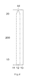
- FIG. 4 shows one notch 44 in the middle of the sampling entrance end. Additional notches could be added along the sampling entrance end, multiple notches could form a saw-tooth like or serrated end.
- one notch with a shape of semi-circle is located in the middle of the sampling entrance end, it will be overlaid with the notch 54 of the second base layer to form a notch 34 , thus creating additional sampling point (see below). Size and shape as well as number of the notch are not critical.
- the notch shape could be, but not limited to, circular arc, square, rectangular, triangle, regular trapezoid, inverted trapezoid.
- a shape of semi-circle with a diameter of 0.1 to 2 mm is used. More preferably, the diameter is around 1 mm.
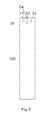
- the second base layer 300 has at least two such cutouts.
- the second base layer 300 has three round cutouts ( 31 , 32 , 33 ) at the end 20 serving as a first working electrode 31 ; a reference electrode 32 and a second working electrode 33 .
- These cutouts have a diameter ranging from 0.1 mm to 2.5 mm.
- the diameter is ranging from 0.5 mm to 1.5 mm. More preferably, it is around 1 mm.
- the electrode cutouts 31 , 32 , 33 have a certain depth, which depends on the thickness of the electric insulating materials used, thus form three wells and can hold chemistries within the wells.
- the thickness of the electric insulating materials is from 0.01 mm to 0.2 mm. More preferably it is around 0.05 mm.
- the electrode cutouts 31 , 32 , 33 in the second base layer 300 have the same shape and dimensions. But they can have different shapes, dimensions and/or arrangement orders, without deviating from the scope and spirit of the present invention.
- the placement of all of the cutouts is such that they will be all positioned within the sample fluid chamber described above.
- the cutouts may be made by die cutting the insulating material mechanically, or cutting with a laser, and then fastening the material to the first base layer.
- the diameter of the semi-circle can be larger than or equal to the width of the first base layer 200 or second base layer 300 . Preferably, it is slightly smaller than the width of the second base layer 300 . More preferably, it is around 2 mm to 20 mm in the present invention. Assuming the test sensor or the component layers ( 200 , 300 , 400 and 500 ) in the present invention have a width of around 6 mm, preferably, the diameter of the semi-circular shaped cutout is around 5.2 mm.
- a double coated, pressure-sensitive adhesive tape may be used as the first upper layer 400 .
- the cutout 41 creating the fluid chamber may have different shapes and size, without deviating from the scope and spirit of the present invention.
- the shape may include, but not limited to semi-circular, circular arc, square, rectangular, triangle, regular trapezoid, inverted trapezoid and etc.
- the cutout is in semi-circular shape.
- the thickness and size of the cutout 41 determine the volume of the capillary chamber.
- the first upper layer 400 has a thickness ranging from 0.01 mm to 0.5 mm, thus, the volume of the fluid chamber is about 0.1 to 5 microliter in the present invention.
- the fluid chamber formed as such allows a blood sample entering the fluid chamber from any part of the entire front opening end.
- the first upper layer 400 is shorter in length at the sampling end 20 compared to the base layers 200 and 300 , as well as the second top layer 500 .
- the two base layers and the second upper layer are aligned at the front end of the sampling end 20 , while the first upper layer is not exposed, thus leaving side openings 91 at the left corner and right corner in communication with the fluid chamber. Therefore, the sampling entrance extends from the front opening and bottom opening to the side openings, forming an over 180 degree extra wide opening.
- a blood sample can enter the fluid chamber from any part of the 180 degree extra wide opening.
- the laminated body may also have a second upper layer 500 a or 500 b, bonded to the first upper layer 400 .
- FIGS. 7A and 7B are top views of the second upper layer without (a) and with (b) vent openings to be used in forming a test sensor according to one embodiment, respectively.
- the second upper layer 500 b is alternative to the second upper layer 500 a.
- the second upper layer 500 a or 500 b virtually has the same width and length as the second base layer 300 .
- the laminated body is shown in FIG. 1A (using 500 b as the second upper layer).
- the second upper layer 500 a or 500 b is made of a plastic or polymer materials.
- Non-limiting examples of polymeric materials, that may be used to form the second upper layer 500 a or 500 b include, but not limited to polyethylene, polyethylene terephthalate, polyethylene naphthalate, polyimide and combinations thereof.
- the second upper layer 500 a or 500 b has a hydrophilic surface facing to the chamber to facilitate the capillary action. It should be understood that the entire side of the second upper layer 500 a or 500 b may be coated with a hydrophilic substance and then bonded to the first upper layer 400 .
- the test sensor of the present invention has five identical round vent openings located along the distal end of the fluid chamber.
- the second upper layer 500 a or 500 b virtually has the same width as the second base layer 300 , but shorter in length, leaving the second base layer 300 partially exposed at the sampling end 20 , and thus creating additional top opening at the front of the sampling entrance.
- the laminated body is shown in FIG. 1B (using 500 b as the second upper layer). It can be seen that the sampling entrance is further widen compared to the first embodiment, which may allow a blood sample to enter the fluid chamber from the top of the sampling entrance.
- the side and front opening plus bottom opening combine to form extra wide sampling opening and allow a total of four sampling routes including the front, left, right, and bottom of the sampling opening.
- the side and front opening plus bottom and top opening combine to form extra wide sampling opening and thus allow a total of five sampling routes including the front, left, right, top and bottom of the sampling opening.
- FIGS. 9A-9C illustrate blood entering the fluid chamber for the test sensor according to the first embodiment of the present invention. Note arrows denote blood sampling directions. Because of the extra wide sampling entrance opening of the present invention, blood sample can enter the fluid chamber from any part of the opening such as, front ( FIG. 9A ); side (left or right, FIG. 9B ) and bottom ( FIG. 9C ). Also note that the test sensor is flipped over in FIG. 9C .
- the test sensor of the present invention more easily receives the fluid sample from a user and is more tolerant to users who jam the tip of the sensor into his/her finger, is more tolerant to fluid samples with very small volume (less than 1 microliter) and even smeared samples on the finger tip or other sampling site.
- the electrode cutouts 31 , 32 , 33 may be loaded with chemistries that react with an analyte to produce detectable electrochemical signals.
- the chemistries may contain an enzyme, an antibody, an antigen, a complexing reagent, a substrate or combination thereof.
- the reagents are selected to react with the desired analyte or analytes to be tested so as to assist in determining an analyte concentration of a fluid sample.
- the reagents typically contain an enzyme such as, for example, glucose oxidase, glucose dehydrogenase, cholesterol oxidase, creatinine amidinohydrolase, lactate oxidase, peroxidase, uricase, xanthine oxidase and etc. which reacts with the analyte and with an electron acceptor such as a ferricyanide salt to produce an electrochemically measurable species that can be detected by the electrodes.
- an enzyme such as, for example, glucose oxidase, glucose dehydrogenase, cholesterol oxidase, creatinine amidinohydrolase, lactate oxidase, peroxidase, uricase, xanthine oxidase and etc. which reacts with the analyte and with an electron acceptor such as a ferricyanide salt to produce an electrochemically measurable species that can be detected by the electrodes.
- the electrode cutouts 31 , 32 , 33 may comprise a mixture of a polymer, an enzyme, a surfactant, an electron acceptor, an electron donor, a buffer, a stabilizer and a binder.
- the electrode cutouts 31 , 32 , 33 may further include a mediator that is an electron acceptor and assists in generating a current that corresponds to the analyte concentration.
- the preferable mediators could be redox chemicals either in oxidized or reduced form.
- the mediator used in the present invention may include, but not limited to various metal or noble metal complexes such as potassium ferricyanide, potassium ferrocyanide, cobalt phthalocyanine, various ferrocenes, and various organic redox mediators such as methylene blue, methylene green, 7,7,8,8-tetracyanoquinodimethane, tetrathiafulvalene, toluidine blue, meldola blue, N-methylphenazine methosulfate, phenyldiamines, 3,3′,5,5′-tetramethylbenzidine, pyrogallol, and benzoquinone, phenanthroline-5,6-dione and etc.
- various metal or noble metal complexes such as potassium ferricyanide, potassium ferrocyanide, cobalt phthalocyanine, various ferrocenes, and various organic redox mediators such as methylene blue, methylene green, 7,7,8,8-tetracyanoquinod
- potassium ferricyanide may be included as redox mediator; if the enzyme used to construct the test sensor includes peroxidase, then potassium ferrocyanide may be included as redox mediator.
- the electrode cutouts 31 , 32 , 33 include a first working electrode 31 , a second working electrode 33 and a reference electrode 32 .
- the second working electrode 33 serves as a blank electrode without loading a chemistry that reacts with the analyte, such that a background signal can be measured and be subtracted from the analyte signal resulted from the first working electrode 31 .
- effect of interference substances on the analyte signal could be minimized.
- the electric signals such as current, impedance at the working electrodes 31 and 33 , and time to obtain these signals could be used to estimate filling status of the fluid chamber (filled or not). Thus, this embodiment could alert under-fill of fluid samples.
- test sensor construction describes construction for a single sensor
- design and materials used can also be used for making multiple sensors from one large piece of each layer material. This would be accomplished by starting with relative large pieces of the first base layer material, second base material, first upper layer material and second upper layer material. After a series of preparations described above, a plurality of multiple test sensors thus can be constructed to achieve mass production in a cost-effective way.
Landscapes
- Life Sciences & Earth Sciences (AREA)
- Health & Medical Sciences (AREA)
- Chemical & Material Sciences (AREA)
- Physics & Mathematics (AREA)
- Molecular Biology (AREA)
- Hematology (AREA)
- Chemical Kinetics & Catalysis (AREA)
- Electrochemistry (AREA)
- Biophysics (AREA)
- Analytical Chemistry (AREA)
- Biochemistry (AREA)
- General Health & Medical Sciences (AREA)
- General Physics & Mathematics (AREA)
- Immunology (AREA)
- Pathology (AREA)
- Investigating Or Analysing Biological Materials (AREA)
Abstract
Description
- The present invention generally relates to a test sensor or strip. More specifically, the present invention generally relates to a disposable biosensor with a thin layer fluid chamber that is adapted to receive a fluid sample with small volume. Still more specifically, the present invention generally relates an electrochemical biosensor with a novel extra wide sampling entrance. Still more specifically, the present invention generally relates an electrochemical biosensor with the fluid chamber with extra wide sampling entrance that can receive a fluid sample from multiple routes. Still more specifically, the present invention relates methods of making and using the biosensors.
- Electrochemical biosensors or disposable test sensors such as strips are well known and have been used to determine the concentration of various analytes from biological samples, particularly from blood. The accurate determination of analytes in body fluids is of great importance in the diagnoses of certain physiological abnormalities. In particular, it is important that diabetic individuals frequently check their glucose level in their body fluids to regulate the glucose intake in their daily diets. The results of such tests can be used to determine the insulin dosage or other medication needs to be administered. In one type of blood-glucose testing system, test sensors, or called glucose strips, are used by diabetic individuals to test a sample of blood in connection with a hand-held meter. The glucose strips are used by millions of diabetics throughout the world on a daily base.
- There are hundreds of brand names of glucose strips in the market. They are very similar in terms of sensor construction: i.e., a channel or chamber is formed between a generally U-shaped spacer and is adapted to receive blood from the opening end of the sensor through capillary action and escape air from the other end through an air escape vent. In order to reduce blood volume, thus reduce pain from piercing finger or other sampling points, the blood receiving chamber is usually small and, as a result, the sampling entrance is also relatively small. As the volume of fluid chambers in the sensors decreases, it becomes increasingly more difficult to fill the fluid chamber with the sample to be analyzed. It has been observed that users may abuse the test sensor by jamming the tip of the test sensor into the individual's finger, which very probably results in incomplete blood filling, non-continuous filling or wiggling of blood flow. Additionally, in some existing test sensors, it is difficult to position the fluid sample within the channel entrance opening especially for those diabetics who have poor vision and/or trembling hands. Besides, blood samples turn to smear around the tip of fingers or other sampling points. It becomes very difficult to draw such smeared blood into the sensor chamber. Each of these shortcomings may, either individually or when combined with one or more of the other shortcomings, contribute to erroneous measurement readings during analysis and may eventually lead to biased readings, and as a result, wrong dosage of insulin administration and even life threatening errors may occur.
- Therefore, in order to reduce or eliminate such biased readings caused by such user action and/or reduce the difficulty in connection with sampling, it would be highly desirable to have a more user friendly test sensor that could easily target sample, easily draw sample into the fluid chamber, and alleviate incomplete filling, non-continuous filling and other issues that may result in inaccurate test results. The present disclosure is directed to a novel design and method to overcome one or more of the limitations in the prior arts.
- According to the first embodiment, a disposable electrochemical test sensor has a fluid sample chamber having a novel extra wide sampling entrance. Such a design is adapted to improve sampling of fluid samples. The fluid chamber provides a reservoir from which sample fluid can be drawn into the sample receiving chamber through capillary action. In preferred embodiments, the sensor consists of multiple layers which include a first base layer having conductive coatings serving as working and reference electrodes and having a notch at the sampling entrance end to create additional sampling point; a second base layer having at least one cutout to define the electrode areas and load chemistries and having a notch at the sampling entrance end to create additional sampling point; a first upper layer having semi-circular shape cutout serving as spacer and being slightly shorter than other layers at the sampling end allowing openings at the left and right corners in communication with the fluid chamber; and a second upper layer with a hydrophilic surface facing to the chamber and vent openings at the distal end of the chamber. The base and upper layers are attached through adhesives or other ways to bond each other. Note that the two base layers and the second upper layer are aligned at the front end while the first upper layer is not exposed at the front end as it is slightly shorter. As such, the fluid chamber is formed between a portion of the lower layer surface and the upper layer surface at one end of the sensor, while the other end of the sensor having conductive layer exposed serve as electric contacts in connection with a monitor or meter. The novel extra wide sampling entrance provided by the present invention can draw blood into the chamber through any part of the sampling entrance opening, i.e. it can draw blood into the chamber not only from the front of the sampling entrance as usual in convenient sensors, but also from the bottom, left corner and right corner of the sampling entrance. Thus it allows easily targeting the samples with small volume, picking up smeared samples and alleviating jamming the opening end.
- According to the second embodiment, a disposable electrochemical test sensor has a fluid sample chamber having a novel extra wide sampling entrance. Such a design is adapted to improve sampling of fluid samples. The fluid chamber provides a reservoir from which sample fluid can be drawn into the sample receiving chamber through capillary action. In preferred embodiments, the sensor consists of multiple layers which include a base layer having conductive coatings serving as working and reference electrodes and having a notch at the sampling entrance end to create additional sampling point; a second base layer used to define the electrode areas and load chemistries and having a notch at the sampling entrance end to create additional sampling point; a first upper layer having semi-circular shape cutout serving as spacer and being slightly shorter than the base layers and being recessed from a front edge of a upper layer sampling end at the sampling end allowing openings at the left and right corners in communication with the fluid chamber; and a second upper layer with a hydrophilic surface facing to the chamber and vent openings at the distal end of the chamber. The second upper layer is slightly longer than the first upper layer at the sampling end, but slightly shorter than the two base layers, such that the corner opening (both left and right) is created and the surface of the second base layer is partially exposed allowing a top opening once the second upper layer is laminated with other layers. The base and upper layers are attached through adhesives or other ways to bond each other. Note that the two base layers are aligned while the first and second upper layers at the sampling entrance end are not aligned as they are different in length. As such, the fluid chamber is formed between a portion of the lower layer surface and the upper layer surface at one end of the sensor, while the other end of the sensor having conductive layer exposed serve as electric contacts in connection with a monitor or meter. The novel extra wide sampling entrance provided by the present invention can draw blood into the chamber through any part of the sampling entrance opening, i.e. it can draw blood into the chamber not only from the front of the sampling entrance as usual in convenient sensors, but also from the top, bottom, left corner and right corner of the sampling entrance. Thus it allows easily targeting the samples with small volume, picking up smeared samples and alleviating jamming the opening end.
- According to one embodiment, a disposable electrochemical test sensor has a sample chamber having a novel extra wide sampling entrance as described in the first and second embodiments, but no additional air escape vent at the second upper layer. Such a design is adapted to improve sampling of fluid samples. The fluid chamber provides a reservoir from which sample fluid can be drawn into the sample receiving chamber through capillary action. The extra wide sampling entrance provided by the present invention can draw blood into the chamber through any part of the opening end. Thus it allows easily targeting the samples with small volume, picking up smeared samples and alleviating jamming the opening end. The extra wide sampling entrance provided by the present invention also serves as the air escape vent. Such one opening sensor eliminates over-flow issue often encountered in convenient sensors.
- According to one method, an analyte concentration is measured. A disposable electrochemical test sensor is provided having a sample chamber having a novel extra wide sampling entrance, The chamber provides a reservoir from which sample fluid can be drawn into the sample receiving chamber through capillary action. In preferred embodiments, the sensor consists of laminated multiple layers which include a base layer having conductive coatings serving as working and reference electrodes and having a notch at the sampling entrance end to create additional sampling point and a second base layer used to define the electrode areas and load chemistries and having a notch at the sampling entrance end to create additional sampling point. The notches at the first and second base layers are overlaid to form a notch at the bottom of the fluid chamber. The shape and size and number of the notch are not critical. In one preferred embodiment of the present invention, the notch is a semi-circle in the middle of the front entrance end. The laminated body also includes a first upper layer serves as spacer which may have different shapes, such as circular arc, square, rectangular, triangle, regular trapezoid, inverted trapezoid; and a second upper layer having a hydrophilic surface facing to the chamber with or without vent openings. The upper and base layers are attached through adhesives or other ways to bond each other, such that the fluid chamber is formed between a portion of the lower layer surface and the upper layer surface at one end of the sensor, while the other end of the sensor having conductive layers exposed serve as electric contacts in connection with a monitor or meter.
- In one preferred embodiment, the sensor consists of multiple layers which include a base layer having conductive coatings serving as working and reference electrodes and a notch at the sampling entrance end to create additional sampling point; a second base layer having at least one cutout to define the electrode areas and hold chemistries and a notch at the sampling entrance end to create additional sampling point; a first upper layer having semi-circular shape serving as a spacer; and a second upper layer with a hydrophilic surface facing to the chamber and vent openings at distal end of the chamber. The upper and base layers are attached such that the fluid chamber is formed between a portion of the lower layer surface and the upper layer surface at one end of the sensor, while the other end of the sensor having conductive layers exposed serves as electric contacts.
-
FIG. 1A provides a perspective view of a first embodiment of the present invention. -
FIG. 1B provides a perspective view of a second embodiment of the present invention. -
FIG. 2 is an exploded view of the test sensor of the present invention showing the four component layers according one embodiment. -
FIG. 3 is a top view of the test sensor of the present invention consisting of four laminated layers according to one embodiment. -
FIG. 4 is a top view of a first base layer to be used in forming a test sensor according to one embodiment. -
FIG. 5 is a top view of the second base layer to be used in forming a test sensor according to one embodiment. -
FIG. 6 is a top view of the first upper layer to be used in forming a test sensor according to one embodiment. -
FIG. 7A provides a top view of the second upper layer without vent openings to be used in forming a test sensor according to one embodiment. -
FIG. 7B provides a top view of the second upper layer with vent openings to be used in forming a test sensor according to one embodiment. -
FIG. 8A provides a side view of a test sensor according to a first embodiment. -
FIG. 8B provides a side view of a test sensor according to a second embodiment. -
FIG. 9A illustrates that blood can enter the fluid chamber of one embodiment of the test sensor from the front of the sampling entrance of the test sensor. -
FIG. 9B illustrates that blood can enter the fluid chamber of one embodiment of the test sensor from the side of the sampling entrance of the test sensor. -
FIG. 9C illustrates that blood can enter the fluid chamber of one embodiment of the test sensor from the bottom of the sampling entrance of the test sensor. -
FIG. 10A illustrates that blood can enter the fluid chamber of another embodiment of the test sensor from the top of the sampling entrance of the test sensor. -
FIG. 10B illustrates that blood can enter the fluid chamber of another embodiment of the test sensor from the front of the sampling entrance of the test sensor. -
FIG. 100 illustrates that blood can enter the fluid chamber of another embodiment of the test sensor from the side of the sampling entrance of the test sensor. -
FIG. 10D illustrates that blood can enter the fluid chamber of another embodiment of the test sensor from the bottom of the sampling entrance of the test sensor. - The test sensor of the present invention is directed to improve sampling entrance of the strip for the determination of an analyte concentration of in a fluid sample, such as blood. In one embodiment, a test sensor is adapted to receive a fluid sample from one end of the sensor, while the other end is connected with an instrument or meter. Analytes that may be measured include, but not limited to glucose, lactate, uric acid, β-hydroxybutyric acid, creatinine, creatine, cholesterol, triglycerides, hemoglobin, bilirubin, alcohol, etc. The fluid sample may be any body fluid, thus, the analytes may be in, for example, a whole blood sample, a blood serum sample, a blood plasma sample, other body fluids like tears, interstitial fluid and urine. In one preferred method, the testing equipment is a hand-held meter.
- In one embodiment, the test sensor is an electrochemical test sensor.
FIG. 1A andFIG. 1B are perspective views of the test sensors of the present invention according to the first embodiment and the second embodiment, respectively. The sensor has asensor body 100, anelectric contact end 10 andsampling end 20. The electric contact end may have at least two contacts used for one working electrode and one reference electrode, respectively. In one preferred embodiment, the electric contact end has three electric contacts serving as contacts for a first working electrode; a second working electrode and a reference electrode, respectively. - In one embodiment, the test sensor consists of multiple layers which include a
first base layer 200; asecond base layer 300; a firstupper layer 400; and a secondupper layer 500, as shown inFIG. 2 . Thefirst base layer 200 made of insulating material has conductive coating on the surface. The conductive surface is separated into three conduits. The separate conductive conduits terminate and are exposed for making an electric connection to a reading device at theend 10 opposite thesampling end 20 of the laminated body. Thefirst base layer 200 also has anotch 44 at the front end of thesampling end 20. Thesecond base layer 300 is made of insulating material having threecutouts sampling end 20 and anotch 54 at the front end of thesampling end 20. The firstupper layer 400 is also made of insulating material and has a semi-circular shapedcutout 41 at thesampling end 20. The secondupper layer 500 is still made of insulating material and has severalsmall openings 74 at thesampling end 20. The secondupper layer 500 has one side coated with hydrophilic layer which faces the fluid chamber. -
FIG. 3 shows a top view of the test sensor consisting of four laminated layers according to one embodiment. Thenotch 34 is combination of thenotch 44 of thefirst base layer 200 and thenotch 54 of thesecond base layer 300 when they are overlaid. 91 denotes the side opening when all the layers are laminated. -
FIG. 4 shows a top view of afirst base layer 200 to be used in forming a test sensor according to one embodiment. Thefirst base layer 200 has three electric conduits for three electrodes at thesampling end 20 and corresponding electric contacts at theelectric contact end 10. It also has anotch 44 in the middle of the sampling entrance end. Thefirst base layer 200 may be made from a variety of insulating materials such as polymeric materials, coated with conductive materials such as carbon, various metals or metal oxides. Thefirst base layer 200 with conductive coating serves as substrate of the test sensor. It also serves as electrodes at oneend 20 and electric contacts at theother end 10. The insulating layers of the laminated body may be made from any dielectric material. The preferred material is a plastic material. Non-limiting examples of polymeric materials, that may be used to form the base layer include, but not limited to polyethylene, polypropylene, polystyrene, polyvinyl chloride, and polytetrafluoroethylene, polycarbonate, polyethylene terephthalate, polyethylene naphthalate, polyimide and combinations thereof. The conductive coating may be formed by a variety of methods which are well known in the field including, but not limited to printing (e.g., screen-printing), coating (e.g., reverse roll), vapor deposition, sputtering, chemical deposition, and electrochemical deposition. The conductive coating may be on a whole piece of insulating material. If so, a desired number of electric conduits must be made. This can be achieved by etching/scribing the required number of conductive conduits. The etching process may be accomplished chemically, by mechanically scribing lines in the conductive layer, or by using a laser to scribe the conductive layer into separate conductive conduits. The conductive materials may be, but not limited to various carbon materials; various noble metals like gold, platinum, palladium, iridium, rhodium, ruthenium; various metal oxides like indium oxide, tin oxide; and combinations thereof. - Although
FIG. 4 shows onenotch 44 in the middle of the sampling entrance end. Additional notches could be added along the sampling entrance end, multiple notches could form a saw-tooth like or serrated end. In one preferred embodiment, one notch with a shape of semi-circle is located in the middle of the sampling entrance end, it will be overlaid with thenotch 54 of the second base layer to form anotch 34, thus creating additional sampling point (see below). Size and shape as well as number of the notch are not critical. The notch shape could be, but not limited to, circular arc, square, rectangular, triangle, regular trapezoid, inverted trapezoid. In one preferred embodiment, a shape of semi-circle with a diameter of 0.1 to 2 mm is used. More preferably, the diameter is around 1 mm. -
FIG. 5 shows a top view of the second base layer to be used in forming a test sensor according to one embodiment. Thesecond base layer 300 virtually has same width as thefirst base layer 200, but shorter in length at theend 10 to expose electric contacts. Thesecond base layer 300 is made of electric insulating layer and it is shorter than the first base layer at theelectric contact end 10 so that conductive coating at the first base layer can be exposed for electric contacts when connected with test monitoring device like a hand-held meter. Thesecond base layer 300 has at least one cutout at theend 20. The cutout exposes a part of the conductive layer when laminated with thefirst base layer 200 and thus defines the electrode area. The cutout can also be loaded with chemistries within the well formed. In one embodiment, thesecond base layer 300 has at least two such cutouts. In one preferred embodiment, thesecond base layer 300 has three round cutouts (31, 32, 33) at theend 20 serving as a first workingelectrode 31; areference electrode 32 and a second workingelectrode 33. These cutouts have a diameter ranging from 0.1 mm to 2.5 mm. Preferably, the diameter is ranging from 0.5 mm to 1.5 mm. More preferably, it is around 1 mm. The electrode cutouts 31, 32, 33 have a certain depth, which depends on the thickness of the electric insulating materials used, thus form three wells and can hold chemistries within the wells. Preferably, the thickness of the electric insulating materials is from 0.01 mm to 0.2 mm. More preferably it is around 0.05 mm. In one embodiment of the present invention, theelectrode cutouts second base layer 300 have the same shape and dimensions. But they can have different shapes, dimensions and/or arrangement orders, without deviating from the scope and spirit of the present invention. The placement of all of the cutouts is such that they will be all positioned within the sample fluid chamber described above. The cutouts may be made by die cutting the insulating material mechanically, or cutting with a laser, and then fastening the material to the first base layer. An adhesive, such as a pressure-sensitive adhesive, may be used to secure the secondbase insulating layer 300 to thefirst base layer 200. Adhesion may also be accomplished by ultrasonically bonding thesecond base layer 300 to thefirst base layer 200. Thesecond base layer 300 may also be made by screen printing an insulating material, by binding a photopolymer or by heat-sealing an insulating material over thefirst base layer 200. - The
second base layer 300 also has anotch 54 in the middle of the sampling entrance end. Preferably, thenotch 54 has the same size, shape and location as thenotch 44 at thefirst base layer 200, such that when all fourlayers notch 44 at the first base layer and thenotch 54 at the second base layer combine and form anotch 34. Thenotch 34 located at the bottom of the sampling entrance opening, thus, creates an extra opening at the bottom of the sampling entrance, which allows a blood sample entering the fluid chamber through the bottom of the test sensor. This is especially significant for a smeared blood which could be picked up by the bottom sampling point. -
FIG. 6 shows a top view of the firstupper layer 400 to be used in forming a test sensor according to one embodiment. The firstupper layer 400 virtually has same width as thesecond base layer 300. The firstupper layer 400 serves as a spacer in between the twobase layers 200/300 and the secondupper layer 500. The firstupper layer 400, or spacer, is also made of a plastic insulating material with glue or adhesive on both sides and creates the sample fluid chamber of the laminated body. It contains a semi-circular shapedcutout 41 at thesampling end 20 which overlays thesecond base layer 300 with the open end corresponding to the open end of the laminated body described earlier. The semi-circular shapedcutout 41 has a diameter of at least 1 mm. The diameter of the semi-circle can be larger than or equal to the width of thefirst base layer 200 orsecond base layer 300. Preferably, it is slightly smaller than the width of thesecond base layer 300. More preferably, it is around 2 mm to 20 mm in the present invention. Assuming the test sensor or the component layers (200, 300, 400 and 500) in the present invention have a width of around 6 mm, preferably, the diameter of the semi-circular shaped cutout is around 5.2 mm. A double coated, pressure-sensitive adhesive tape may be used as the firstupper layer 400. Thecutout 41 creating the fluid chamber may have different shapes and size, without deviating from the scope and spirit of the present invention. The shape may include, but not limited to semi-circular, circular arc, square, rectangular, triangle, regular trapezoid, inverted trapezoid and etc. In one preferred embodiment, the cutout is in semi-circular shape. The thickness and size of thecutout 41 determine the volume of the capillary chamber. Preferably, the firstupper layer 400 has a thickness ranging from 0.01 mm to 0.5 mm, thus, the volume of the fluid chamber is about 0.1 to 5 microliter in the present invention. The fluid chamber formed as such allows a blood sample entering the fluid chamber from any part of the entire front opening end. Besides, the firstupper layer 400 is shorter in length at thesampling end 20 compared to the base layers 200 and 300, as well as the secondtop layer 500. As a result, the two base layers and the second upper layer are aligned at the front end of thesampling end 20, while the first upper layer is not exposed, thus leavingside openings 91 at the left corner and right corner in communication with the fluid chamber. Therefore, the sampling entrance extends from the front opening and bottom opening to the side openings, forming an over 180 degree extra wide opening. A blood sample can enter the fluid chamber from any part of the 180 degree extra wide opening. - The laminated body may also have a second
upper layer upper layer 400.FIGS. 7A and 7B are top views of the second upper layer without (a) and with (b) vent openings to be used in forming a test sensor according to one embodiment, respectively. The secondupper layer 500 b is alternative to the secondupper layer 500 a. - According to the first embodiment, the second
upper layer second base layer 300. The laminated body is shown inFIG. 1A (using 500 b as the second upper layer). The secondupper layer upper layer upper layer upper layer upper layer 400. - In case of using 500 a as the second upper layer, there are no additional vent openings. Because of the unique design of the extra wide sampling entrance in the present invention, air escape is not an issue when a fluid sample such as blood enter the fluid chamber. Air can always find a way to escape from some part of the wide opening. Therefore, the test sensor of the present invention combines the sampling entrance and air escape vent in one extra wide opening. In case of using 500 b as the second upper layer, there are several small vent openings located at the distal end of the chamber. The multiple small vent openings function as air escape vents when a blood sample enters the fluid chamber. It has been found out that multiple small vent openings instead of a large vent opening can effectively eliminates over-flow issues often encountered in conventional sensors. In one preferred embodiment, there are at least two small round vent openings located along the distal end of the fluid chamber. Preferably, the diameter of the openings is less than 0.5 mm. More preferably, it is around 0.1 mm. The test sensor of the present invention has five identical round vent openings located along the distal end of the fluid chamber.
- According to the second embodiment, the second
upper layer second base layer 300, but shorter in length, leaving thesecond base layer 300 partially exposed at thesampling end 20, and thus creating additional top opening at the front of the sampling entrance. The laminated body is shown inFIG. 1B (using 500 b as the second upper layer). It can be seen that the sampling entrance is further widen compared to the first embodiment, which may allow a blood sample to enter the fluid chamber from the top of the sampling entrance. To facilitate a sampling from the top, it would be desirable to coat the entiresecond base layer 300 or at least exposed area with a hydrophilic layer. In one preferred embodiment, it would be desirable to partially or entirely coat thesecond base layer 300 with a hydrophilic layer. More preferably, it would be desirable to merely coat the exposed part of thesecond base layer 300 with a hydrophilic layer. -
FIGS. 8A and 8B are side views of the test sensors consisting of four laminated layers including afirst base layer 200,second base layer 300, firstupper layer 400 and secondupper layer 500 according to the first embodiment (FIG. 8A ) and second embodiment (FIG. 8B ) of the present invention, respectively. It should be pointed that the secondupper layer 500 is aligned with the twobase layers sampling end 20 for the first embodiment of the present invention, while it is recessed slightly from the twobase layers side opening 91 is preferably from 0.01 mm to 2.5 mm. More preferably, it is from 0.1 to 0.3 mm. Still more preferably, it is around 0.25 mm. It should be emphasized that theside opening 91 in the unique design of the present invention is just a part of the extra wide sampling opening. - In the first embodiment, the side and front opening plus bottom opening combine to form extra wide sampling opening and allow a total of four sampling routes including the front, left, right, and bottom of the sampling opening. In the second embodiment, the side and front opening plus bottom and top opening combine to form extra wide sampling opening and thus allow a total of five sampling routes including the front, left, right, top and bottom of the sampling opening. The advantage of the test sensor of such three-dimension sampling entrances for blood sampling can be illustrated through
FIGS. 9 and 10 . -
FIGS. 9A-9C illustrate blood entering the fluid chamber for the test sensor according to the first embodiment of the present invention. Note arrows denote blood sampling directions. Because of the extra wide sampling entrance opening of the present invention, blood sample can enter the fluid chamber from any part of the opening such as, front (FIG. 9A ); side (left or right,FIG. 9B ) and bottom (FIG. 9C ). Also note that the test sensor is flipped over inFIG. 9C . -
FIGS. 10A-10D illustrate blood entering the fluid chamber for the test sensor according to the second embodiment of the present invention. Note arrows denote blood sampling directions. Because of the extra wide sampling entrance opening of the present invention, blood sample can enter the fluid chamber from any part of the opening such as, top (FIG. 10A ); front (FIG. 10B ); side (left or right,FIG. 100 ) and bottom (FIG. 10D ). Note that the test sensor is flipped over inFIG. 10D . - By having a test sensor with the extra wide openings in the first embodiment or second embodiment, being adapted to receive a fluid sample, the test sensor of the present invention more easily receives the fluid sample from a user and is more tolerant to users who jam the tip of the sensor into his/her finger, is more tolerant to fluid samples with very small volume (less than 1 microliter) and even smeared samples on the finger tip or other sampling site.
- Referring back to
FIGS. 1-3 , theelectrode cutouts - In order for the test sensor to work effectively, the
electrode cutouts - The electrode cutouts 31, 32, 33 include a first working
electrode 31, a second workingelectrode 33 and areference electrode 32. In one embodiment, the second workingelectrode 33 serves as a blank electrode without loading a chemistry that reacts with the analyte, such that a background signal can be measured and be subtracted from the analyte signal resulted from the first workingelectrode 31. In this embodiment, effect of interference substances on the analyte signal could be minimized. Still in this embodiment, the electric signals such as current, impedance at the workingelectrodes - Although the description of test sensor construction above describes construction for a single sensor, the design and materials used can also be used for making multiple sensors from one large piece of each layer material. This would be accomplished by starting with relative large pieces of the first base layer material, second base material, first upper layer material and second upper layer material. After a series of preparations described above, a plurality of multiple test sensors thus can be constructed to achieve mass production in a cost-effective way.
- It should be noted that although the particular embodiments of the present invention have been described herein, the above description is merely for illustration purpose. Further modification and variations of the invention herein disclosed will occur to those skilled in the respective arts and all such modifications and variations are deemed to be within the scope of the invention as defined by the appended claims.
Claims (20)
Priority Applications (1)
| Application Number | Priority Date | Filing Date | Title |
|---|---|---|---|
| US15/905,000 US10386323B2 (en) | 2014-02-20 | 2018-02-26 | Test sensor with multiple sampling routes |
Applications Claiming Priority (2)
| Application Number | Priority Date | Filing Date | Title |
|---|---|---|---|
| US14/184,764 US9939401B2 (en) | 2014-02-20 | 2014-02-20 | Test sensor with multiple sampling routes |
| US15/905,000 US10386323B2 (en) | 2014-02-20 | 2018-02-26 | Test sensor with multiple sampling routes |
Related Parent Applications (1)
| Application Number | Title | Priority Date | Filing Date |
|---|---|---|---|
| US14/184,764 Continuation US9939401B2 (en) | 2014-02-20 | 2014-02-20 | Test sensor with multiple sampling routes |
Publications (2)
| Publication Number | Publication Date |
|---|---|
| US20180188198A1 true US20180188198A1 (en) | 2018-07-05 |
| US10386323B2 US10386323B2 (en) | 2019-08-20 |
Family
ID=53797900
Family Applications (2)
| Application Number | Title | Priority Date | Filing Date |
|---|---|---|---|
| US14/184,764 Active 2035-05-11 US9939401B2 (en) | 2014-02-20 | 2014-02-20 | Test sensor with multiple sampling routes |
| US15/905,000 Active 2034-03-08 US10386323B2 (en) | 2014-02-20 | 2018-02-26 | Test sensor with multiple sampling routes |
Family Applications Before (1)
| Application Number | Title | Priority Date | Filing Date |
|---|---|---|---|
| US14/184,764 Active 2035-05-11 US9939401B2 (en) | 2014-02-20 | 2014-02-20 | Test sensor with multiple sampling routes |
Country Status (2)
| Country | Link |
|---|---|
| US (2) | US9939401B2 (en) |
| WO (1) | WO2015126456A1 (en) |
Families Citing this family (4)
| Publication number | Priority date | Publication date | Assignee | Title |
|---|---|---|---|---|
| US9897566B2 (en) * | 2014-01-13 | 2018-02-20 | Changsha Sinocare Inc. | Disposable test sensor |
| US9939401B2 (en) * | 2014-02-20 | 2018-04-10 | Changsha Sinocare Inc. | Test sensor with multiple sampling routes |
| JP7595068B2 (en) * | 2020-03-23 | 2024-12-05 | テルモ株式会社 | Test Strips |
| US12484818B2 (en) * | 2021-06-14 | 2025-12-02 | Arizona Board Of Regents On Behalf Of Arizona State University | Wearable, continuous biological fluid monitoring system |
Family Cites Families (90)
| Publication number | Priority date | Publication date | Assignee | Title |
|---|---|---|---|---|
| JPS57118152A (en) | 1981-01-14 | 1982-07-22 | Matsushita Electric Ind Co Ltd | Enzyme electrode |
| US4534356A (en) | 1982-07-30 | 1985-08-13 | Diamond Shamrock Chemicals Company | Solid state transcutaneous blood gas sensors |
| JPS59178354A (en) | 1983-03-29 | 1984-10-09 | Ngk Spark Plug Co Ltd | Oxygen sensor |
| FR2580137A1 (en) | 1985-04-05 | 1986-10-10 | Omron Tateisi Electronics Co | Assembly of electronic components |
| US5128015A (en) | 1988-03-15 | 1992-07-07 | Tall Oak Ventures | Method and apparatus for amperometric diagnostic analysis |
| WO1989009397A1 (en) | 1988-03-31 | 1989-10-05 | Matsushita Electric Industrial Co., Ltd. | Biosensor and process for its production |
| GB8817421D0 (en) | 1988-07-21 | 1988-08-24 | Medisense Inc | Bioelectrochemical electrodes |
| GB8927377D0 (en) | 1989-12-04 | 1990-01-31 | Univ Edinburgh | Improvements in and relating to amperometric assays |
| JPH03183943A (en) | 1989-12-14 | 1991-08-09 | Hitachi Ltd | Oxygen sensor |
| NO172250C (en) | 1990-05-07 | 1993-06-23 | Elkem Aluminium | DEVICE FOR CLOSING THE ANODETOPE ON A SODER BERGANODEI AN ELECTROLYCLE CELL FOR ALUMINUM PRODUCTION |
| JP3025027B2 (en) | 1991-01-21 | 2000-03-27 | 株式会社日立製作所 | Oxygen sensor |
| US5264103A (en) | 1991-10-18 | 1993-11-23 | Matsushita Electric Industrial Co., Ltd. | Biosensor and a method for measuring a concentration of a substrate in a sample |
| US5762770A (en) | 1994-02-21 | 1998-06-09 | Boehringer Mannheim Corporation | Electrochemical biosensor test strip |
| US5437999A (en) | 1994-02-22 | 1995-08-01 | Boehringer Mannheim Corporation | Electrochemical sensor |
| JP3027306B2 (en) | 1994-06-02 | 2000-04-04 | 松下電器産業株式会社 | Biosensor and manufacturing method thereof |
| EP0792584A4 (en) | 1994-07-29 | 2004-12-29 | Toto Ltd | Strongly acidic sterile water containing low-concentration hypochlorous acid, method of forming strongly acidic sterile water containing low-concentration hypochlorous acid, apparatus therefor, and apparatus for forming and delivering strongly acidic sterile water containing low-concentration hypoch |
| US5582697A (en) | 1995-03-17 | 1996-12-10 | Matsushita Electric Industrial Co., Ltd. | Biosensor, and a method and a device for quantifying a substrate in a sample liquid using the same |
| US5665222A (en) | 1995-10-11 | 1997-09-09 | E. Heller & Company | Soybean peroxidase electrochemical sensor |
| AUPN661995A0 (en) | 1995-11-16 | 1995-12-07 | Memtec America Corporation | Electrochemical cell 2 |
| JP3365184B2 (en) | 1996-01-10 | 2003-01-08 | 松下電器産業株式会社 | Biosensor |
| US5708247A (en) | 1996-02-14 | 1998-01-13 | Selfcare, Inc. | Disposable glucose test strips, and methods and compositions for making same |
| US6071391A (en) | 1997-09-12 | 2000-06-06 | Nok Corporation | Enzyme electrode structure |
| US5997817A (en) | 1997-12-05 | 1999-12-07 | Roche Diagnostics Corporation | Electrochemical biosensor test strip |
| JP3896435B2 (en) | 1997-12-17 | 2007-03-22 | アークレイ株式会社 | Sensor and sensor assembly |
| US5975153A (en) | 1998-02-13 | 1999-11-02 | Roche Diagnostics Corporation | Capillary fill test device with improved fluid delivery |
| WO1999053301A1 (en) | 1998-04-14 | 1999-10-21 | The Regents Of The University Of California | Sensor probe for determining hydrogen peroxide concentration and method of use thereof |
| GB2337122B (en) | 1998-05-08 | 2002-11-13 | Medisense Inc | Test strip |
| GB2339615B (en) | 1998-07-14 | 2001-02-07 | Cozart Bioscience Ltd | Screening device and method of screening an immunoassay test |
| JP2000162176A (en) | 1998-09-22 | 2000-06-16 | Omron Corp | Measuring method and measuring device using biosensor |
| US6338790B1 (en) | 1998-10-08 | 2002-01-15 | Therasense, Inc. | Small volume in vitro analyte sensor with diffusible or non-leachable redox mediator |
| US6287451B1 (en) | 1999-06-02 | 2001-09-11 | Handani Winarta | Disposable sensor and method of making |
| US6645359B1 (en) | 2000-10-06 | 2003-11-11 | Roche Diagnostics Corporation | Biosensor |
| US7276146B2 (en) | 2001-11-16 | 2007-10-02 | Roche Diagnostics Operations, Inc. | Electrodes, methods, apparatuses comprising micro-electrode arrays |
| US7073246B2 (en) | 1999-10-04 | 2006-07-11 | Roche Diagnostics Operations, Inc. | Method of making a biosensor |
| US20050103624A1 (en) | 1999-10-04 | 2005-05-19 | Bhullar Raghbir S. | Biosensor and method of making |
| US6767440B1 (en) | 2001-04-24 | 2004-07-27 | Roche Diagnostics Corporation | Biosensor |
| US6923894B2 (en) | 1999-11-11 | 2005-08-02 | Apex Biotechnology Corporation | Biosensor with multiple sampling ways |
| CN100363739C (en) | 1999-11-15 | 2008-01-23 | 松下电器产业株式会社 | Biosensor, thin-film electrode forming method, quantification device, and quantification method |
| US6428664B1 (en) | 2000-06-19 | 2002-08-06 | Roche Diagnostics Corporation | Biosensor |
| US6803205B2 (en) | 2000-11-08 | 2004-10-12 | Surface Logix, Inc. | Methods of measuring enzyme activity using peelable and resealable devices |
| US6793802B2 (en) | 2001-01-04 | 2004-09-21 | Tyson Bioresearch, Inc. | Biosensors having improved sample application and measuring properties and uses thereof |
| KR100426638B1 (en) | 2001-07-07 | 2004-04-08 | 주식회사 인포피아 | Glucose strip sensor and glucose measurement method by the strip sensor |
| WO2003010530A1 (en) | 2001-07-27 | 2003-02-06 | Arkray, Inc. | Analyzing instrument |
| US6767441B1 (en) | 2001-07-31 | 2004-07-27 | Nova Biomedical Corporation | Biosensor with peroxidase enzyme |
| US6787013B2 (en) | 2001-09-10 | 2004-09-07 | Eumed Biotechnology Co., Ltd. | Biosensor |
| US20030116447A1 (en) | 2001-11-16 | 2003-06-26 | Surridge Nigel A. | Electrodes, methods, apparatuses comprising micro-electrode arrays |
| US6942770B2 (en) | 2002-04-19 | 2005-09-13 | Nova Biomedical Corporation | Disposable sub-microliter volume biosensor with enhanced sample inlet |
| DE10220296A1 (en) | 2002-05-07 | 2003-11-20 | Roche Diagnostics Gmbh | Device for sampling liquid samples |
| US7291256B2 (en) | 2002-09-12 | 2007-11-06 | Lifescan, Inc. | Mediator stabilized reagent compositions and methods for their use in electrochemical analyte detection assays |
| KR100554649B1 (en) | 2003-06-09 | 2006-02-24 | 주식회사 아이센스 | Electrochemical Biosensor |
| US7063776B2 (en) | 2003-06-17 | 2006-06-20 | Chun-Mu Huang | Structure and manufacturing method of disposable electrochemical sensor strip |
| US8187446B2 (en) | 2003-06-17 | 2012-05-29 | Chun-Mu Huang | Method of manufacturing a disposable electrochemical sensor strip |
| EP1642124B1 (en) | 2003-06-20 | 2017-11-29 | Roche Diabetes Care GmbH | Electrochemical biosensors |
| US8071030B2 (en) | 2003-06-20 | 2011-12-06 | Roche Diagnostics Operations, Inc. | Test strip with flared sample receiving chamber |
| WO2004113900A2 (en) | 2003-06-20 | 2004-12-29 | Roche Diagnostics Gmbh | Test strip with flared sample receiving chamber |
| JP4458802B2 (en) | 2003-10-02 | 2010-04-28 | パナソニック株式会社 | Method for measuring glucose in blood and sensor used therefor |
| CA2545477C (en) | 2003-12-04 | 2016-06-21 | Matsushita Electric Industrial Co., Ltd. | Method of measuring hematocrit (hct), sensor used in the method, and measuring device |
| EP3273232A2 (en) | 2003-12-04 | 2018-01-24 | Panasonic Healthcare Holdings Co., Ltd. | Method of measuring blood component, sensor used in the method, and measuring device |
| PL2705792T3 (en) | 2004-03-06 | 2015-10-30 | Hoffmann La Roche | Body fluid sampling device |
| US7118667B2 (en) | 2004-06-02 | 2006-10-10 | Jin Po Lee | Biosensors having improved sample application and uses thereof |
| US7299081B2 (en) | 2004-06-15 | 2007-11-20 | Abbott Laboratories | Analyte test device |
| US8323464B2 (en) | 2005-05-25 | 2012-12-04 | Universal Biosensors Pty Ltd | Method and apparatus for electrochemical analysis |
| US7922883B2 (en) | 2005-06-08 | 2011-04-12 | Abbott Laboratories | Biosensors and methods of using the same |
| EP1924855A1 (en) | 2005-08-30 | 2008-05-28 | Bayer Healthcare, LLC | A test sensor with a fluid chamber opening |
| KR101009365B1 (en) | 2005-09-02 | 2011-01-19 | 아크레이 인코퍼레이티드 | Sample supply status detection method and analysis tool |
| US7918975B2 (en) | 2005-11-17 | 2011-04-05 | Abbott Diabetes Care Inc. | Analytical sensors for biological fluid |
| US8617366B2 (en) | 2005-12-12 | 2013-12-31 | Nova Biomedical Corporation | Disposable urea sensor and system for determining creatinine and urea nitrogen-to-creatinine ratio in a single device |
| US7955484B2 (en) | 2005-12-14 | 2011-06-07 | Nova Biomedical Corporation | Glucose biosensor and method |
| US20090215159A1 (en) | 2006-01-23 | 2009-08-27 | Quidel Corporation | Device for handling and analysis of a biological sample |
| US7811430B2 (en) | 2006-02-28 | 2010-10-12 | Abbott Diabetes Care Inc. | Biosensors and methods of making |
| US8529751B2 (en) | 2006-03-31 | 2013-09-10 | Lifescan, Inc. | Systems and methods for discriminating control solution from a physiological sample |
| BR122018005191B8 (en) | 2006-04-11 | 2021-07-27 | Trividia Health Inc | test strip manufacturing method |
| US20080006530A1 (en) | 2006-06-19 | 2008-01-10 | Handani Winarta | Capillary Flow Control in a Flow Channel |
| KR100829400B1 (en) | 2006-11-30 | 2008-05-15 | 주식회사 인포피아 | Biosensor |
| US7802467B2 (en) | 2006-12-22 | 2010-09-28 | Abbott Diabetes Care Inc. | Analyte sensors and methods of use |
| JP5357876B2 (en) | 2007-07-31 | 2013-12-04 | バイエル・ヘルスケア・エルエルシー | Test sensor and instrument contacts attached to the side |
| US7837660B2 (en) | 2007-12-17 | 2010-11-23 | Ross Peter Jones | Recessed electrodes for sensing flow in ophthalmic surgical system |
| US8357276B2 (en) | 2009-08-31 | 2013-01-22 | Abbott Diabetes Care Inc. | Small volume test strips with large sample fill ports, supported test strips, and methods of making and using same |
| US8888973B2 (en) | 2011-07-29 | 2014-11-18 | Roche Diagnostics Operations, Inc. | Encoded biosensors and methods of manufacture and use thereof |
| US8603309B2 (en) | 2011-09-12 | 2013-12-10 | Nova Biomedical Corporation | Disposable sensor for electrochemical detection of hemoglobin |
| US20130199942A1 (en) | 2012-02-07 | 2013-08-08 | Lifescan Scotland Limited | Electrochemical-based analytical test strip with fill-speed configured reagent layer |
| US20140054171A1 (en) | 2012-02-21 | 2014-02-27 | Abbott Diabetes Care Inc. | Analyte Sensor Utilizing Oxygen as Oxidant |
| JP2013257310A (en) | 2012-05-18 | 2013-12-26 | Arkray Inc | Biosensor |
| US8877023B2 (en) | 2012-06-21 | 2014-11-04 | Lifescan Scotland Limited | Electrochemical-based analytical test strip with intersecting sample-receiving chambers |
| TWI481863B (en) | 2012-07-20 | 2015-04-21 | Apex Biotechnology Corp | Electrode strip and sensor strip and manufacture method thereof and measurement system with hematocrit correction |
| KR20140066377A (en) | 2012-11-23 | 2014-06-02 | 삼성전자주식회사 | Bio-sensor |
| US10041901B2 (en) | 2013-03-15 | 2018-08-07 | Roche Diabetes Care, Inc. | Electrode configuration for a biosensor |
| US9523653B2 (en) * | 2013-05-09 | 2016-12-20 | Changsha Sinocare Inc. | Disposable test sensor with improved sampling entrance |
| US9518951B2 (en) * | 2013-12-06 | 2016-12-13 | Changsha Sinocare Inc. | Disposable test sensor with improved sampling entrance |
| US9939401B2 (en) * | 2014-02-20 | 2018-04-10 | Changsha Sinocare Inc. | Test sensor with multiple sampling routes |
-
2014
- 2014-02-20 US US14/184,764 patent/US9939401B2/en active Active
- 2014-09-11 WO PCT/US2014/055157 patent/WO2015126456A1/en not_active Ceased
-
2018
- 2018-02-26 US US15/905,000 patent/US10386323B2/en active Active
Also Published As
| Publication number | Publication date |
|---|---|
| WO2015126456A1 (en) | 2015-08-27 |
| US20150233861A1 (en) | 2015-08-20 |
| US9939401B2 (en) | 2018-04-10 |
| US10386323B2 (en) | 2019-08-20 |
Similar Documents
| Publication | Publication Date | Title |
|---|---|---|
| US10571425B2 (en) | Disposable test sensor with improved sampling entrance | |
| US7918975B2 (en) | Analytical sensors for biological fluid | |
| TWI434038B (en) | Analyte sensors and methods of use | |
| US9869653B2 (en) | Electrochemical sensors with carrier field | |
| US10386323B2 (en) | Test sensor with multiple sampling routes | |
| US10527576B2 (en) | Disposable test sensor with improved sampling entrance | |
| US20190017956A1 (en) | Disposable test sensor | |
| CN203535003U (en) | Biosensor | |
| CN103091377B (en) | Biosensor | |
| CN203534868U (en) | Biosensor | |
| HK1195126B (en) | Electrochemical sensors with carrier field | |
| HK1195126A (en) | Electrochemical sensors with carrier field |
Legal Events
| Date | Code | Title | Description |
|---|---|---|---|
| FEPP | Fee payment procedure |
Free format text: ENTITY STATUS SET TO UNDISCOUNTED (ORIGINAL EVENT CODE: BIG.); ENTITY STATUS OF PATENT OWNER: LARGE ENTITY |
|
| AS | Assignment |
Owner name: CHANGSHA SINOCARE INC., CHINA Free format text: ASSIGNMENT OF ASSIGNORS INTEREST;ASSIGNORS:CAI, XIAOHUA;CHE, HONGLI;LI, SHAOBO;REEL/FRAME:047030/0373 Effective date: 20140219 |
|
| STPP | Information on status: patent application and granting procedure in general |
Free format text: RESPONSE TO NON-FINAL OFFICE ACTION ENTERED AND FORWARDED TO EXAMINER |
|
| STPP | Information on status: patent application and granting procedure in general |
Free format text: NOTICE OF ALLOWANCE MAILED -- APPLICATION RECEIVED IN OFFICE OF PUBLICATIONS |
|
| STPP | Information on status: patent application and granting procedure in general |
Free format text: PUBLICATIONS -- ISSUE FEE PAYMENT RECEIVED |
|
| STPP | Information on status: patent application and granting procedure in general |
Free format text: PUBLICATIONS -- ISSUE FEE PAYMENT VERIFIED |
|
| STCF | Information on status: patent grant |
Free format text: PATENTED CASE |
|
| MAFP | Maintenance fee payment |
Free format text: PAYMENT OF MAINTENANCE FEE, 4TH YEAR, LARGE ENTITY (ORIGINAL EVENT CODE: M1551); ENTITY STATUS OF PATENT OWNER: LARGE ENTITY Year of fee payment: 4 |