US20180146292A1 - A headband for a pair of headphones, a corresponding pair of headphones and a method of providing the headband - Google Patents
A headband for a pair of headphones, a corresponding pair of headphones and a method of providing the headband Download PDFInfo
- Publication number
- US20180146292A1 US20180146292A1 US15/577,499 US201615577499A US2018146292A1 US 20180146292 A1 US20180146292 A1 US 20180146292A1 US 201615577499 A US201615577499 A US 201615577499A US 2018146292 A1 US2018146292 A1 US 2018146292A1
- Authority
- US
- United States
- Prior art keywords
- elongated strip
- headband
- leg
- groove
- headphones
- Prior art date
- Legal status (The legal status is an assumption and is not a legal conclusion. Google has not performed a legal analysis and makes no representation as to the accuracy of the status listed.)
- Granted
Links
Images


Classifications
-
- H—ELECTRICITY
- H04—ELECTRIC COMMUNICATION TECHNIQUE
- H04R—LOUDSPEAKERS, MICROPHONES, GRAMOPHONE PICK-UPS OR LIKE ACOUSTIC ELECTROMECHANICAL TRANSDUCERS; ELECTRIC HEARING AIDS; PUBLIC ADDRESS SYSTEMS
- H04R5/00—Stereophonic arrangements
- H04R5/033—Headphones for stereophonic communication
- H04R5/0335—Earpiece support, e.g. headbands or neckrests
-
- H—ELECTRICITY
- H04—ELECTRIC COMMUNICATION TECHNIQUE
- H04R—LOUDSPEAKERS, MICROPHONES, GRAMOPHONE PICK-UPS OR LIKE ACOUSTIC ELECTROMECHANICAL TRANSDUCERS; ELECTRIC HEARING AIDS; PUBLIC ADDRESS SYSTEMS
- H04R1/00—Details of transducers, loudspeakers or microphones
- H04R1/10—Earpieces; Attachments therefor ; Earphones; Monophonic headphones
- H04R1/105—Earpiece supports, e.g. ear hooks
-
- H—ELECTRICITY
- H04—ELECTRIC COMMUNICATION TECHNIQUE
- H04R—LOUDSPEAKERS, MICROPHONES, GRAMOPHONE PICK-UPS OR LIKE ACOUSTIC ELECTROMECHANICAL TRANSDUCERS; ELECTRIC HEARING AIDS; PUBLIC ADDRESS SYSTEMS
- H04R1/00—Details of transducers, loudspeakers or microphones
- H04R1/10—Earpieces; Attachments therefor ; Earphones; Monophonic headphones
- H04R1/1008—Earpieces of the supra-aural or circum-aural type
-
- H—ELECTRICITY
- H04—ELECTRIC COMMUNICATION TECHNIQUE
- H04R—LOUDSPEAKERS, MICROPHONES, GRAMOPHONE PICK-UPS OR LIKE ACOUSTIC ELECTROMECHANICAL TRANSDUCERS; ELECTRIC HEARING AIDS; PUBLIC ADDRESS SYSTEMS
- H04R1/00—Details of transducers, loudspeakers or microphones
- H04R1/10—Earpieces; Attachments therefor ; Earphones; Monophonic headphones
- H04R1/1033—Cables or cables storage, e.g. cable reels
Definitions
- the present disclosure generally relates to the field of headphones.
- the embodiments of the present invention relate to a headband for a pair of headphones, a corresponding pair of headphones and a method of providing the headband.
- FIG. 1 shows an example of a pair of headphones 100 .
- the pair of headphones 100 typically comprises a headband 110 .
- the headband 110 is an arced headband.
- the headband 110 is generally configured to extend along a portion of a head of a user, or wearer, of the pair of headphones 100 .
- Each headband end 120 is provided with a respective earpiece 130 .
- Each of the two earpieces 130 comprises respective speaker elements, etc. (not shown), as is conventional and known in the existing art.
- the earpieces 130 also provide a volume around (or at) the ears of the user such that the pair of headphones 100 may be worn conveniently by the user and such that the sound listening experience is satisfactory when using the pair of headphones 100 .
- the two earpieces 130 should typically press sufficiently towards the ears of the user (or, the areas of the head which are proximate to the respective ears), during use.
- This force i.e. the force with which the earpieces 130 press against the ears of the user during use, is sometimes referred to as the clamp force.
- This clamp force may also be important to allow for the pair of headphones 100 to stay in place on the head of the user, when in use. Additionally, the clamp force may be important to enable the sealing of the sound when the earpieces 130 are provided around (or at) the ears of the user.
- the pair of headphones 100 can be worn conveniently.
- a headband for a pair of headphones comprises an elongated strip made of a flexible material.
- This elongated strip comprises a first end configured to be attached to a first earpiece and a second end configured to be attached to a second earpiece.
- the elongated strip is configured to extend in a curvature from the first end to the second end to form an arced strip.
- This arced strip is configured to extend along a portion of a head of a user of the pair of headphones.
- the headband also comprises a leg made of a rigid material. The leg abuts against the elongated strip and extends along the elongated strip from the first end to the second end.
- the leg may advantageously, but not necessarily, be positioned along a center portion of the elongated strip.
- a rigid leg abutting against a flexible elongated strip has the combined effect of 1) enabling a sufficient clamp force to allow for pressing two earpieces properly against the ears of the user (in use) and, at the same time, 2) enabling a rotational movement of the elongated strip around the leg which in turn allows for a suitable adjustment to a user's head. In turn, this may provide a more comfortable and pleasant experience when using a pair of headphones. Additionally, this disclosure recognizes the fact that the rotational movement makes it possible to adapt to the angles of the ears. In turn, this makes the headband ambidextrous and the headband can adapt to the left as well as the right ear of a user.
- the elongated strip comprises a groove (or, recess) which extends from the first end to the second end.
- the leg is insertable in this groove.
- the leg can be inserted in the groove.
- one or several snap connections may optionally be provided along the groove e.g. to facilitate insertion of the leg in the groove.
- the leg is displaceable in a longitudinal direction of the elongated strip at each of the first and second ends such that the leg is fee to move back and forth within the respective end.
- the groove may optionally comprise a stop member at each end of the groove.
- the leg is instead irremovably attached to the elongated strip.
- the leg may be attached to the elongated strip by means of an adhesive, such as glue.
- the leg is enclosed by the flexible elongated strip.
- this could be achieved by an injection molding process, during which process the leg is enclosed by the flexible elongated strip.
- the elongated strip may for example comprise a tubular leg receiving means (or, tube) wherein the leg is inserted into said tubular leg receiving means.
- a plurality of tubular section parts may provided along a groove of the elongated strip.
- the elongated strip may comprise alternately reoccurring tubular section parts that collectively form a regular pattern along the groove.
- the above-mentioned leg may be a spring wire.
- the spring wire may have a diameter of 1.6-2.2 millimeters, and preferably 1.8-2.0 millimeters.
- the spring wire may e.g. comprise a metal or a metal alloy.
- the spring wire may be made of a steel alloy.
- the spring wire may be made of an aluminum alloy.
- the spring wire may comprise glass fiber.
- the spring wire could be made of glass fiber and titanium.
- the spring wire may comprise carbon fiber.
- the above-mentioned elongated strip is made of a polymer material.
- the elongated strip may, for example, comprise any one or a combination of the following materials: polyamide (PA), polycarbonates (PC), polyethylene (PE), high-density polyethylene (HDPE), polyethylene terephthalate (PTE), polyvinyl chloride (PVC), polypropylene (PP), thermoplastic elastomer (TPE), thermoplastic polyurethane (TPU), and acrylonitrile butadiene styrene (ABS).
- PA polyamide
- PC polycarbonates
- PE polyethylene
- HDPE high-density polyethylene
- PTE polyethylene terephthalate
- PVC polyvinyl chloride
- PP polypropylene
- TPE thermoplastic elastomer
- TPU thermoplastic polyurethane
- ABS acrylonitrile butadiene styrene
- This general object has therefore been addressed by the appended claim 17 .
- An advantageous embodiment is further defined in appended claim 18 .
- a pair of headphones comprises a headband according to the first aspect, wherein the first end is attached to a first earpiece and the second end is attached to a second earpiece.
- the pair of headphones comprising a headband, wherein the headband comprises:
- the elongated strip comprises a groove (or, recess) which extends from the first end to the second end of the elongated strip.
- the leg is insertable in this groove. In other words, the leg can be inserted in the groove.
- first end is attached to a first earpiece by means of a first pivot hinge and the second end is attached to the second earpiece by means of a second pivot hinge.
- Each pivot hinge may comprise a recess (or, notch) configured to receive an audio cable such that the audio cable can extend from the first earpiece along the strip to the second ear piece.
- a method of providing a headband for a pair of headphones comprises providing an elongated strip made of a flexible material, wherein the elongated strip comprises a first end configured to be attached to a first earpiece and a second end configured to be attached to a second earpiece, and wherein the elongated strip extends in a curvature from the first end to the second end to form an arced strip which is configured to extend along a portion of a head of a user of the headband; providing one leg made of a rigid material; and engaging the leg with the elongated strip such that leg abuts to the elongated strip and such that the leg extends along the elongated strip from the first end to the second end and is further preferably (but not necessarily) positioned along a center portion of the elongated strip.
- the elongated strip comprises a groove which extends from the first end to the second end. If so, the step of engaging the leg with the elongated strip comprises inserting the leg in the groove of the elongated strip.
- FIG. 1 shows a perspective view of a pair of headphones
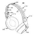
- FIG. 2A schematically illustrates an isometric view of a pair of headphones, in accordance with an embodiment
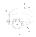
- FIG. 2B is a side view of the pair of headphones illustrated in FIG. 2A ;
- FIG. 2C is a front view of the pair of headphones illustrated in FIGS. 2A and 2B ;
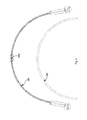
- FIG. 3 is a front view of a headband and a leg of the pair of headphones illustrated in FIGS. 2A-2C ;
- FIG. 4A schematically illustrates an isometric view of the headband of the pair of headphones shown in FIGS. 2A-2C ;
- FIG. 4B is a front view of the headband illustrated in FIG. 4A ;
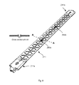
- FIG. 5 is an enlarged side view at cross section AA, as illustrated in FIG. 4B ;
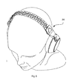
- FIG. 6 schematically illustrates a user wearing a pair of headphones as illustrated in FIG. 2A ;
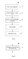
- FIG. 7A is a flowchart of method of providing a headband for a pair of headphones, in accordance with an embodiment.
- FIG. 7B is a flowchart of a sub-step, or action, of a method of providing a headband for a pair of headphones, in accordance with an embodiment.
- FIG. 8 schematically illustrates an embodiment of an elongated strip having a plurality of snap connections
- FIG. 9 schematically illustrates an embodiment of an elongated strip being provided with a tubular leg receiving means, or tube;
- FIG. 10 schematically illustrates an embodiment of an elongated strip having a plurality of tubular section parts along a groove of the elongated strip.
- a headband 210 for a pair of headphones 200 in accordance with an embodiment will be described in detail.
- the headband comprises an elongated strip 211 of flexible (or, pliable) material.
- the elongated strip 211 may be made of a polymer material.
- the elongated strip 211 may, for instance, comprise one or several of the following example materials: polyamide (PA), polycarbonates (PC), polyethylene (PE), high-density polyethylene (HDPE), polyethylene terephthalate (PTE), polyvinyl chloride (PVC), polypropylene (PP), thermoplastic elastomer (TPE), thermoplastic polyurethane (TPU) and acrylonitrile butadiene styrene (ABS).
- PA polyamide
- PC polycarbonates
- PE polyethylene
- HDPE high-density polyethylene
- PTE polyethylene terephthalate
- PVC polyvinyl chloride
- PP polypropylene
- TPE thermoplastic elastomer
- TPU thermoplastic polyurethane
- ABS acrylonitrile butadiene
- the elongated strip 211 comprises a first end 211 a configured to be attached to a first earpiece 230 a .
- the first end 211 a is configured to be removably (or, alternatively, irremovably) attached to the first earpiece 230 a .
- the elongated strip 211 also comprises a second end 211 b configured to be attached to a second earpiece 230 b .
- the second end 211 b is configured to be removably (or, alternatively, irremovably) attached to the first earpiece 230 b .
- the first end 211 a may be attached to the first earpiece 230 a by means of a first pivot hinge 240 a .
- the second end 211 b may be attached to the second earpiece 230 b by means of a second pivot hinge 240 b .
- Each pivot hinge may additionally comprise a recess 241 b (see FIG. 4A ), or notch, configured to receive an audio cable such that the audio cable can extend from the first earpiece 230 a along the elongated strip 211 to the second ear piece 230 b.
- the elongated strip 211 is configured to extend in a curvature from the first end 211 a to the second end 211 b to form an arced strip, which is configured to extend along a portion of a head of a user (see e.g. FIG. 6 ).
- a leg 220 made of a rigid material is provided.
- the leg 220 is exemplified by a spring wire.
- the leg 220 is generally abutting against the elongated strip 211 .
- the leg 220 also extends along the elongated strip 211 from the first end 211 a thereof to the second end 211 b thereof.
- the leg 220 also extends in a curvature from the first end 211 a to the second end 211 b to form an arced leg 220 .
- the arced leg 220 is also configured to extend along a portion of a head of a user.
- the leg 220 is advantageously positioned along a center portion C of the elongated strip 211 . While it is preferred to position the leg 220 along the center portion C of the elongated strip 211 , a person skilled in the art would appreciate that it is not necessary to position the leg 220 at the exact center of the elongated strip 211 . A certain deviation from the exact center of the elongated strip 211 is of course possible to achieve the same or similar effects with respect to the rotation of the flexible elongated strip 211 around the comparatively more rigid leg 220 .
- the spring wire shown in FIGS. 2 through 5 has a diameter of 1.6-2.2 millimeters, and preferably 1.8-2.0 millimeters.
- the spring wire may e.g. comprise a metal or a metal alloy.
- the spring wire may be made of a steel alloy.
- the spring wire may be made of an aluminum alloy.
- the spring wire may comprise glass fiber.
- the spring wire could be made of glass fiber and titanium.
- the spring wire may comprise carbon fiber.
- the elongated strip 211 may advantageously be provided with a groove 250 , or recess, for receiving the leg 220 .
- the groove 250 may extend from the first end 211 a to the second end 211 b and the leg 220 can be inserted into the groove 250 .
- the groove 250 may advantageously, but not necessarily, be positioned at an inner surface of the elongated strip 211 such that the leg 220 is configured to face, or abut, a portion of a head of a user when the user wears the pair of headphones 200 .
- one or several snap connections 260 a - c may also be provided along the groove 250 to facilitate insertion of the leg 220 in the groove 250 .
- the one or several snap connection 260 a - c may also allow for the leg 220 to maintain its position in the groove 250 during use. The one or several snap connection can thus eliminate the risk that the leg 220 would slip, or fall, out from the groove 250 during use.
- the leg 200 may advantageously be displaceable in a longitudinal direction of the elongated strip 211 (i.e., at the end portions within the groove 250 , in which the leg 220 rests) at each of the first and second ends 211 a , 211 b such that the leg 220 is fee to move back and forth within the respective end 211 a , 211 b.
- the groove 250 may optionally also comprise stop members 251 a , 251 b at each end of the groove 250 .
- the stop member 251 a , 251 b may e.g. be provided by dead ends of the groove 250 .
- An advantage with dead ends is that these are relatively easy to provide, or manufacture and hence the provision, or manufacturing, of these dead ends is also relatively inexpensive.
- a rigid leg 220 abutting against a flexible elongated strip inter alia has the effect of enabling a sufficient clamp force to allow for pressing the two earpieces 230 a , 230 b properly against the ears of the user, when in use.
- this construction of the headband 210 also enables a rotational movement of the elongated strip 211 around the leg 220 which in turn allows for a suitable adjustment to a user's head. In turn, this may provide a more comfortable and pleasant experience when using of a pair of headphones.
- leg 220 e.g. a spring wire
- a leg which is instead attached to the elongated strip.
- the leg could e.g. be attached to the elongated strip by means of an adhesive, such as glue.
- Still another option is to provide a leg, which is instead enclosed by the flexible elongated strip.
- the leg 220 has been exemplified by a spring wire so far in this disclosure.
- this spring wire could equivalently be replaced by a strip of rigid material.
- a rigid strip may be a generally flat strip.
- Such a flat strip may have a width which is considerably narrower than the corresponding width of the earlier-mentioned elongated strip 211 made of the flexible material.
- the cross-section of a spring wire may take different shapes. While a circular cross-section may be advantageous, rectangular or oval cross-sections may be equally possible.
- FIGS. 2 through 6 suggest the provision of one single leg 220 , it should be appreciated that more than one leg could be provided.
- two or three legs could run in parallel along the elongated strip 211 , i.e. from the first end 211 a to the second end 211 b .
- the two or three legs would preferably have relatively short widths or diameters (e.g., 0.4-0.8 millimeters each) and, also, be positioned relatively close to each other at a center portion of the elongated strip 211 .
- a user may wear a pair of headphones such as illustrated in FIG. 6 .
- a headband cover may be irremovably attached to, or folded around, the headband 210 .
- an interchangeable headband cover may be removably attached to, or folded around, the headband 210 .
- the interchangeable headband cover may be of a type disclosed in the Swedish Patent Application no. 1450950-9, filed on Aug. 15, 2014 and entitled “A headband cover for a headband of a headphone” (now Swedish Patent No. 537 776).
- an interchangeable headband cover for detachable attachment to the headband 210 may be provided.
- the interchangeable headband cover may, for example, comprise: a first headband cover unit; a second headband cover unit, which is arranged along a first longitudinal side of the first headband cover unit; and a third headband cover unit, which is arranged along a second longitudinal side of the first headband cover unit, the second longitudinal side being an opposite side to the first longitudinal side; wherein the second headband cover unit is foldable along the first longitudinal side of the first headband cover unit and the third headband cover unit is foldable along the second longitudinal side of the first headband cover unit such that the second and third headband units can be folded around the headband 210 of the pair of headphones 200 to detachably attach the headband cover to the headband 210 of the pair of headphones 200 .
- the elongated strip 211 may optionally also be provided with through slots 270 along its length from the first end 211 a to the second end 211 b .
- This may allow for an improved flexibility of the elongated strip 211 , which in turn may facilitate the rotational movement around the leg 220 even further.
- the plurality of through slots 270 may allow for reducing the weight of the headband 210 . In turn, this may allow for a lightweight headband 210 .
- FIG. 7A a method 700 of providing a headband 210 for a pair of headphones 200 will be described.
- An elongated strip made of a flexible material is provided.
- the elongated strip comprises a first end configured to be attached to a first earpiece and a second end configured to be attached to a second earpiece.
- the elongated strip is configured to extend in a curvature from the first end to the second end to form an arced strip, which is configured to extend along a portion of a head of a user of the headband.
- a leg e.g. a spring wire, of a rigid material is provided.
- Action 730 The leg is engaged with the elongated strip to abut to the elongated strip and to extend along the elongated strip from the first end to the second end.
- an operator may put the leg into contact with the elongated strip such that the leg abuts the elongated strip and extends along the elongated strip from the first end to the second end thereof.
- the leg may advantageously be positioned along a center portion of the elongated strip.
- the elongated strip comprises a groove which extends from the first end to the second end. If so, the step, or action, of engaging the leg with the elongated strip comprises inserting the leg into the groove of the elongated strip.
- the method may also comprise attaching a first earpiece to the first end of the headband.
- a second earpiece may be attached to the second end of the headband.
- an audio cable (and/or other cable(s)) may also be provided.
- an audio cable extending from the first earpiece may be inserted in a groove, or notch, at the first pivot hinge and be put along the flexible elongated strip and, further, inserted in a groove, or notch, at the second pivot hinge to connect to the second earpiece.
- the method may also comprise attaching a headband cover to the headband.
- the headband may for example be irremovably attached to, or folded around, the headband.
- an interchangeable headband cover may be removably attached to, or folded around, the headband.
- the elongated strip 211 is made of a flexible material. Furthermore, the elongated strip comprises a first end 211 a configured to be attached to a first earpiece 230 a and a second end 211 b configured to be attached to a second earpiece 230 b . Still further, the elongated strip 211 is configured to extend in a curvature from the first end 211 a to the second end 211 b to form an arced strip 211 . The arced strip 211 is configured to extend along a portion of a head of a user of the pair of headphones 200 .
- the groove 250 is positioned along a center portion of the elongated strip 211 . While it is advantageous to position, or locate, the groove 250 along a center portion of the elongated strip 211 , this is however not necessary. A person skilled in the art would appreciate that it is not necessary to position the leg 220 at the exact center of the elongated strip 211 . A certain deviation from the exact center of the elongated strip 211 is of course possible to achieve the same or similar effects with respect to the rotation of the flexible elongated strip 211 around the comparatively more rigid leg 220 .
- FIG. 8 illustrates an embodiment where one or several snap connections 260 a ; 260 b are provided along the groove 250 of the elongated strip 211 . This may have the effect of facilitating the insertion of the leg 220 in the groove 250 .
- the provision of the one or several snap connections 260 a ; 260 b along the groove 250 may also achieve good stability during the use of the headband.
- FIG. 9 illustrates an embodiment where the leg 220 is enclosed by the elongated strip 211 .
- the elongated strip 211 may be provided with a tubular leg receiving means 280 .
- the tubular leg receiving means 280 may sometimes be referred to as “tube” only.
- the tubular leg receiving means 280 is configured to receive the leg 220 .
- the leg 220 may be inserted into the tubular leg receiving means 280 .
- the tubular leg receiving means 280 may be provided as one single tubular leg receiving means 280 extending from the first end 211 a to the second end 211 b of the elongated strip 211 .
- the provision of the tubular leg receiving means 280 may achieve good stability during the use of the headband.
- FIG. 10 illustrates yet another embodiment.
- a plurality of tubular section parts 290 a - j is provided along the groove 250 .
- the elongated strip 211 comprises alternately reoccurring tubular section parts that collectively form a regular pattern along the groove 250 .
- the provision of the plurality of tubular section parts 290 a - j along the groove may facilitate the insertion of the leg 220 in the groove 250 .
- the provision of the plurality of tubular section parts 290 a - j along the groove 250 may also achieve good stability during the use of the headband.
- a headband for a pair of headphones which is easy to adjust according to the size of a user's head and which, at the same time, will adjust itself to the shape of a user's head.
- the provision of a rigid leg abutting against a flexible elongated strip (e.g., inserted in a groove), for example, in a center portion thereof has the combined effect of enabling a sufficient clamp force to allow for pressing two earpieces properly against the ears of the user (in use) and, at the same, enabling a rotational movement of the elongated strip around the leg which in turn allows for a suitable adjustment to a user's head. In turn, this may provide a more comfortable and pleasant experience when using a pair of headphones.
- a headband 210 for a pair of headphones 200 comprising:
Landscapes
- Physics & Mathematics (AREA)
- Engineering & Computer Science (AREA)
- Acoustics & Sound (AREA)
- Signal Processing (AREA)
- Health & Medical Sciences (AREA)
- Otolaryngology (AREA)
- Headphones And Earphones (AREA)
Abstract
Description
- The present disclosure generally relates to the field of headphones. The embodiments of the present invention relate to a headband for a pair of headphones, a corresponding pair of headphones and a method of providing the headband.
- Headphones are known in the art.
FIG. 1 shows an example of a pair ofheadphones 100. In the existing art, the pair ofheadphones 100 typically comprises aheadband 110. Typically, but not necessarily, theheadband 110 is an arced headband. Theheadband 110 is generally configured to extend along a portion of a head of a user, or wearer, of the pair ofheadphones 100. Eachheadband end 120 is provided with arespective earpiece 130. Each of the twoearpieces 130 comprises respective speaker elements, etc. (not shown), as is conventional and known in the existing art. Theearpieces 130 also provide a volume around (or at) the ears of the user such that the pair ofheadphones 100 may be worn conveniently by the user and such that the sound listening experience is satisfactory when using the pair ofheadphones 100. - In order to provide a sound listening experience that is satisfactory when using a pair of headphones of the type shown in
FIG. 1 , the twoearpieces 130 should typically press sufficiently towards the ears of the user (or, the areas of the head which are proximate to the respective ears), during use. This force, i.e. the force with which theearpieces 130 press against the ears of the user during use, is sometimes referred to as the clamp force. This clamp force may also be important to allow for the pair ofheadphones 100 to stay in place on the head of the user, when in use. Additionally, the clamp force may be important to enable the sealing of the sound when theearpieces 130 are provided around (or at) the ears of the user. At the same time, it is recognized that it may be equally important that the pair ofheadphones 100 can be worn conveniently. In order to allow forheadphones 100 that can be worn conveniently, it is becoming increasingly important to allow for personalized headphones which can be adjusted to different sizes and/or shapes of users' heads. - It is in view of the above considerations and others that the various embodiments of the present invention have been made.
- It is a general object to provide a headband which is easy to adjust according to the size of a user's head and which, at the same time, will adjust itself to the shape of a user's head. This general object has therefore been addressed by the appended independent claim 1. Advantageous embodiments are defined in the appended dependent claims 2-16.
- According to a first aspect, a headband for a pair of headphones is therefore provided. The headband comprises an elongated strip made of a flexible material. This elongated strip comprises a first end configured to be attached to a first earpiece and a second end configured to be attached to a second earpiece. Furthermore, the elongated strip is configured to extend in a curvature from the first end to the second end to form an arced strip. This arced strip is configured to extend along a portion of a head of a user of the pair of headphones. The headband also comprises a leg made of a rigid material. The leg abuts against the elongated strip and extends along the elongated strip from the first end to the second end.
- The leg may advantageously, but not necessarily, be positioned along a center portion of the elongated strip.
- The provision of a rigid leg abutting against a flexible elongated strip (preferably in a center portion thereof) has the combined effect of 1) enabling a sufficient clamp force to allow for pressing two earpieces properly against the ears of the user (in use) and, at the same time, 2) enabling a rotational movement of the elongated strip around the leg which in turn allows for a suitable adjustment to a user's head. In turn, this may provide a more comfortable and pleasant experience when using a pair of headphones. Additionally, this disclosure recognizes the fact that the rotational movement makes it possible to adapt to the angles of the ears. In turn, this makes the headband ambidextrous and the headband can adapt to the left as well as the right ear of a user.
- In an advantageous embodiment, the elongated strip comprises a groove (or, recess) which extends from the first end to the second end. The leg is insertable in this groove. Thus, the leg can be inserted in the groove.
- Furthermore, one or several snap connections may optionally be provided along the groove e.g. to facilitate insertion of the leg in the groove. In some embodiments, the leg is displaceable in a longitudinal direction of the elongated strip at each of the first and second ends such that the leg is fee to move back and forth within the respective end. Furthermore, the groove may optionally comprise a stop member at each end of the groove. The provision of a groove (or, recess) in which the leg can be inserted is advantageous because the manufacturing of the headband can be simplified. Hence, the manufacturing of the headband can also be relatively inexpensive.
- In an alternative embodiment, the leg is instead irremovably attached to the elongated strip. For example, the leg may be attached to the elongated strip by means of an adhesive, such as glue.
- In yet another alternative embodiment, the leg is enclosed by the flexible elongated strip. For example, this could be achieved by an injection molding process, during which process the leg is enclosed by the flexible elongated strip. In some embodiments, the elongated strip may for example comprise a tubular leg receiving means (or, tube) wherein the leg is inserted into said tubular leg receiving means.
- In some embodiments, a plurality of tubular section parts may provided along a groove of the elongated strip. For example, the elongated strip may comprise alternately reoccurring tubular section parts that collectively form a regular pattern along the groove.
- Typically, but not necessarily, the above-mentioned leg may be a spring wire. Advantageously, the spring wire may have a diameter of 1.6-2.2 millimeters, and preferably 1.8-2.0 millimeters. The spring wire may e.g. comprise a metal or a metal alloy. In some embodiments, the spring wire may be made of a steel alloy. In alternative embodiments, the spring wire may be made of an aluminum alloy. Additionally, or alternatively, the spring wire may comprise glass fiber. For example, the spring wire could be made of glass fiber and titanium. Additionally, or alternatively, the spring wire may comprise carbon fiber.
- Typically, but not necessarily, the above-mentioned elongated strip is made of a polymer material.
- The elongated strip may, for example, comprise any one or a combination of the following materials: polyamide (PA), polycarbonates (PC), polyethylene (PE), high-density polyethylene (HDPE), polyethylene terephthalate (PTE), polyvinyl chloride (PVC), polypropylene (PP), thermoplastic elastomer (TPE), thermoplastic polyurethane (TPU), and acrylonitrile butadiene styrene (ABS).
- It is another general object to provide a pair of headphones which is easy to adjust according to the size of a user's head and which, at the same time, will adjust itself to the shape of a user's head. This general object has therefore been addressed by the appended claim 17. An advantageous embodiment is further defined in appended claim 18.
- According to a second aspect, a pair of headphones is therefore provided. The pair of headphones comprises a headband according to the first aspect, wherein the first end is attached to a first earpiece and the second end is attached to a second earpiece. In other words, there is a provided pair of headphones comprising a headband, wherein the headband comprises:
-
- an elongated strip made of a flexible material, wherein the elongated strip comprises a first end attached to a first earpiece and a second end attached to a second earpiece, and wherein the elongated strip is configured to extend in a curvature from the first end to the second end to form an arced strip which is configured to extend along a portion of a head of a user of the pair of headphones; and
- a leg made of a rigid material, the leg abutting against the elongated strip and extending along the elongated strip from the first end to the second end and wherein the leg is preferably (but not necessarily) positioned along a center portion of the elongated strip.
- In an advantageous embodiment, the elongated strip comprises a groove (or, recess) which extends from the first end to the second end of the elongated strip. The leg is insertable in this groove. In other words, the leg can be inserted in the groove.
- In an advantageous embodiment, the first end is attached to a first earpiece by means of a first pivot hinge and the second end is attached to the second earpiece by means of a second pivot hinge. Each pivot hinge may comprise a recess (or, notch) configured to receive an audio cable such that the audio cable can extend from the first earpiece along the strip to the second ear piece.
- It is still another general object to provide a simplified method of providing a headband for a pair of headphones. This general object has therefore been addressed by the appended claim 19.
- According to a third aspect, a method of providing a headband for a pair of headphones is therefore provided. The method comprises providing an elongated strip made of a flexible material, wherein the elongated strip comprises a first end configured to be attached to a first earpiece and a second end configured to be attached to a second earpiece, and wherein the elongated strip extends in a curvature from the first end to the second end to form an arced strip which is configured to extend along a portion of a head of a user of the headband; providing one leg made of a rigid material; and engaging the leg with the elongated strip such that leg abuts to the elongated strip and such that the leg extends along the elongated strip from the first end to the second end and is further preferably (but not necessarily) positioned along a center portion of the elongated strip.
- In an advantageous embodiment, the elongated strip comprises a groove which extends from the first end to the second end. If so, the step of engaging the leg with the elongated strip comprises inserting the leg in the groove of the elongated strip.
- These and other aspects, features and advantages will be apparent and elucidated from the following description of various embodiments, reference being made to the accompanying drawings, in which:
-
FIG. 1 shows a perspective view of a pair of headphones; -
FIG. 2A schematically illustrates an isometric view of a pair of headphones, in accordance with an embodiment; -
FIG. 2B is a side view of the pair of headphones illustrated inFIG. 2A ; -
FIG. 2C is a front view of the pair of headphones illustrated inFIGS. 2A and 2B ; -
FIG. 3 is a front view of a headband and a leg of the pair of headphones illustrated inFIGS. 2A-2C ; -
FIG. 4A schematically illustrates an isometric view of the headband of the pair of headphones shown inFIGS. 2A-2C ; -
FIG. 4B is a front view of the headband illustrated inFIG. 4A ; -
FIG. 5 is an enlarged side view at cross section AA, as illustrated inFIG. 4B ; -
FIG. 6 schematically illustrates a user wearing a pair of headphones as illustrated inFIG. 2A ; -
FIG. 7A is a flowchart of method of providing a headband for a pair of headphones, in accordance with an embodiment; and -
FIG. 7B is a flowchart of a sub-step, or action, of a method of providing a headband for a pair of headphones, in accordance with an embodiment. -
FIG. 8 schematically illustrates an embodiment of an elongated strip having a plurality of snap connections; -
FIG. 9 schematically illustrates an embodiment of an elongated strip being provided with a tubular leg receiving means, or tube; and -
FIG. 10 schematically illustrates an embodiment of an elongated strip having a plurality of tubular section parts along a groove of the elongated strip. - The present invention will now be described more fully hereinafter. The invention may, however, be embodied in many different forms and should not be construed as limited to the embodiments set forth herein; rather, these embodiments are provided by way of example so that this disclosure will be thorough and complete, and will fully convey the scope of the invention to those persons skilled in the art. Like reference numbers refer to like elements throughout the description.
- With reference to
FIGS. 2 through 6 , aheadband 210 for a pair ofheadphones 200 in accordance with an embodiment will be described in detail. - The headband comprises an
elongated strip 211 of flexible (or, pliable) material. For example, theelongated strip 211 may be made of a polymer material. Theelongated strip 211 may, for instance, comprise one or several of the following example materials: polyamide (PA), polycarbonates (PC), polyethylene (PE), high-density polyethylene (HDPE), polyethylene terephthalate (PTE), polyvinyl chloride (PVC), polypropylene (PP), thermoplastic elastomer (TPE), thermoplastic polyurethane (TPU) and acrylonitrile butadiene styrene (ABS). - The
elongated strip 211 comprises afirst end 211 a configured to be attached to afirst earpiece 230 a. In other words, thefirst end 211 a is configured to be removably (or, alternatively, irremovably) attached to thefirst earpiece 230 a. Theelongated strip 211 also comprises asecond end 211 b configured to be attached to asecond earpiece 230 b. In other words, thesecond end 211 b is configured to be removably (or, alternatively, irremovably) attached to thefirst earpiece 230 b. Advantageously, but not necessarily, thefirst end 211 a may be attached to thefirst earpiece 230 a by means of afirst pivot hinge 240 a. Likewise, thesecond end 211 b may be attached to thesecond earpiece 230 b by means of asecond pivot hinge 240 b. Each pivot hinge may additionally comprise arecess 241 b (seeFIG. 4A ), or notch, configured to receive an audio cable such that the audio cable can extend from thefirst earpiece 230 a along theelongated strip 211 to thesecond ear piece 230 b. - As can be seen in the
FIGS. 2 through 6 , theelongated strip 211 is configured to extend in a curvature from thefirst end 211 a to thesecond end 211 b to form an arced strip, which is configured to extend along a portion of a head of a user (see e.g.FIG. 6 ). - Furthermore, a
leg 220 made of a rigid material is provided. In the embodiment illustrated inFIGS. 2 through 5 , theleg 220 is exemplified by a spring wire. As can be seen inFIGS. 2 through 5 , theleg 220 is generally abutting against theelongated strip 211. Theleg 220 also extends along theelongated strip 211 from thefirst end 211 a thereof to thesecond end 211 b thereof. Hence, theleg 220 also extends in a curvature from thefirst end 211 a to thesecond end 211 b to form anarced leg 220. Thearced leg 220 is also configured to extend along a portion of a head of a user. - In order to allow for a proper rotation of the
elongated strip 211 around theleg 220, theleg 220 is advantageously positioned along a center portion C of theelongated strip 211. While it is preferred to position theleg 220 along the center portion C of theelongated strip 211, a person skilled in the art would appreciate that it is not necessary to position theleg 220 at the exact center of theelongated strip 211. A certain deviation from the exact center of theelongated strip 211 is of course possible to achieve the same or similar effects with respect to the rotation of the flexibleelongated strip 211 around the comparatively morerigid leg 220. - Advantageously, the spring wire shown in
FIGS. 2 through 5 has a diameter of 1.6-2.2 millimeters, and preferably 1.8-2.0 millimeters. The spring wire may e.g. comprise a metal or a metal alloy. In some embodiments, the spring wire may be made of a steel alloy. In alternative embodiments, the spring wire may be made of an aluminum alloy. Additionally, or alternatively, the spring wire may comprise glass fiber. For example, the spring wire could be made of glass fiber and titanium. Additionally, or alternatively, the spring wire may comprise carbon fiber. - With continued reference to
FIGS. 2-5 , it should be appreciated that theelongated strip 211 may advantageously be provided with agroove 250, or recess, for receiving theleg 220. Thegroove 250 may extend from thefirst end 211 a to thesecond end 211 b and theleg 220 can be inserted into thegroove 250. In some embodiments, thegroove 250 may advantageously, but not necessarily, be positioned at an inner surface of theelongated strip 211 such that theleg 220 is configured to face, or abut, a portion of a head of a user when the user wears the pair ofheadphones 200. - Advantageously, one or several snap connections 260 a-c may also be provided along the
groove 250 to facilitate insertion of theleg 220 in thegroove 250. The one or several snap connection 260 a-c may also allow for theleg 220 to maintain its position in thegroove 250 during use. The one or several snap connection can thus eliminate the risk that theleg 220 would slip, or fall, out from thegroove 250 during use. - In order to further facilitate the rotation of the flexible
elongated strip 211 around the comparatively morerigid leg 220, theleg 200 may advantageously be displaceable in a longitudinal direction of the elongated strip 211 (i.e., at the end portions within thegroove 250, in which theleg 220 rests) at each of the first and second ends 211 a, 211 b such that theleg 220 is fee to move back and forth within therespective end - In order to limit the movement in said longitudinal direction, the
groove 250 may optionally also comprise stopmembers groove 250. Thestop member groove 250. An advantage with dead ends is that these are relatively easy to provide, or manufacture and hence the provision, or manufacturing, of these dead ends is also relatively inexpensive. - The provision of a
rigid leg 220 abutting against a flexible elongated strip (e.g., in a center portion thereof) inter alia has the effect of enabling a sufficient clamp force to allow for pressing the twoearpieces FIG. 4A , this construction of theheadband 210 also enables a rotational movement of theelongated strip 211 around theleg 220 which in turn allows for a suitable adjustment to a user's head. In turn, this may provide a more comfortable and pleasant experience when using of a pair of headphones. - Although advantageous embodiments of the invention have been described with reference to
FIGS. 2 through 5 hereinabove, modifications and other variants of the described embodiments will come to mind to one skilled in the art having benefit of the teachings presented hereinabove. For example, instead of providing a leg 220 (e.g. a spring wire) in agroove 220 it is equally possible to provide a leg which is instead attached to the elongated strip. The leg could e.g. be attached to the elongated strip by means of an adhesive, such as glue. Still another option is to provide a leg, which is instead enclosed by the flexible elongated strip. Furthermore, theleg 220 has been exemplified by a spring wire so far in this disclosure. However, a person skilled in the art would readily appreciate that this spring wire could equivalently be replaced by a strip of rigid material. For example, such a rigid strip may be a generally flat strip. Such a flat strip may have a width which is considerably narrower than the corresponding width of the earlier-mentionedelongated strip 211 made of the flexible material. As a mere example, it would be conceivable to provide a flat strip of rigid material having a width of approximately 20% of the corresponding width of theelongated strip 211, which is made of the flexible material. Persons skilled in the art would also recognize that the cross-section of a spring wire may take different shapes. While a circular cross-section may be advantageous, rectangular or oval cross-sections may be equally possible. Still further, while the embodiments described with respect toFIGS. 2 through 6 suggest the provision of onesingle leg 220, it should be appreciated that more than one leg could be provided. For example, two or three legs could run in parallel along theelongated strip 211, i.e. from thefirst end 211 a to thesecond end 211 b. In order to allow for a proper rotation of the flexibleelongated strip 211 around the plurality of the comparatively more rigid legs, the two or three legs would preferably have relatively short widths or diameters (e.g., 0.4-0.8 millimeters each) and, also, be positioned relatively close to each other at a center portion of theelongated strip 211. - In some embodiments, a user may wear a pair of headphones such as illustrated in
FIG. 6 . In alternative embodiments, a headband cover may be irremovably attached to, or folded around, theheadband 210. In yet other embodiments, an interchangeable headband cover may be removably attached to, or folded around, theheadband 210. For example, the interchangeable headband cover may be of a type disclosed in the Swedish Patent Application no. 1450950-9, filed on Aug. 15, 2014 and entitled “A headband cover for a headband of a headphone” (now Swedish Patent No. 537 776). To this end, an interchangeable headband cover for detachable attachment to theheadband 210 may be provided. The interchangeable headband cover may, for example, comprise: a first headband cover unit; a second headband cover unit, which is arranged along a first longitudinal side of the first headband cover unit; and a third headband cover unit, which is arranged along a second longitudinal side of the first headband cover unit, the second longitudinal side being an opposite side to the first longitudinal side; wherein the second headband cover unit is foldable along the first longitudinal side of the first headband cover unit and the third headband cover unit is foldable along the second longitudinal side of the first headband cover unit such that the second and third headband units can be folded around theheadband 210 of the pair ofheadphones 200 to detachably attach the headband cover to theheadband 210 of the pair ofheadphones 200. - As can be seen in the
FIGS. 2 through 6 , theelongated strip 211 may optionally also be provided with throughslots 270 along its length from thefirst end 211 a to thesecond end 211 b. This may allow for an improved flexibility of theelongated strip 211, which in turn may facilitate the rotational movement around theleg 220 even further. Also, the plurality of throughslots 270 may allow for reducing the weight of theheadband 210. In turn, this may allow for alightweight headband 210. - Turning now to
FIG. 7A , amethod 700 of providing aheadband 210 for a pair ofheadphones 200 will be described. - Action 710: An elongated strip made of a flexible material is provided. As described earlier, the elongated strip comprises a first end configured to be attached to a first earpiece and a second end configured to be attached to a second earpiece. Furthermore, the elongated strip is configured to extend in a curvature from the first end to the second end to form an arced strip, which is configured to extend along a portion of a head of a user of the headband.
- Action 720: A leg, e.g. a spring wire, of a rigid material is provided.
- Action 730: The leg is engaged with the elongated strip to abut to the elongated strip and to extend along the elongated strip from the first end to the second end. In other words, an operator may put the leg into contact with the elongated strip such that the leg abuts the elongated strip and extends along the elongated strip from the first end to the second end thereof. Furthermore, the leg may advantageously be positioned along a center portion of the elongated strip.
- Action 731: In an advantageous embodiment as illustrated in
FIG. 7B , the elongated strip comprises a groove which extends from the first end to the second end. If so, the step, or action, of engaging the leg with the elongated strip comprises inserting the leg into the groove of the elongated strip. - Action 740: The method may also comprise attaching a first earpiece to the first end of the headband. Also, a second earpiece may be attached to the second end of the headband. During this step, or action, an audio cable (and/or other cable(s)) may also be provided. For example, an audio cable extending from the first earpiece may be inserted in a groove, or notch, at the first pivot hinge and be put along the flexible elongated strip and, further, inserted in a groove, or notch, at the second pivot hinge to connect to the second earpiece.
- Action 750: Optionally, the method may also comprise attaching a headband cover to the headband. The headband may for example be irremovably attached to, or folded around, the headband. Alternatively, an interchangeable headband cover may be removably attached to, or folded around, the headband.
- Reference is now made to
FIGS. 8 through 10 , which schematically illustrate various advantageous embodiments of theelongated strip 211 described hitherto in this disclosure. As described earlier herein, theelongated strip 211 is made of a flexible material. Furthermore, the elongated strip comprises afirst end 211 a configured to be attached to afirst earpiece 230 a and asecond end 211 b configured to be attached to asecond earpiece 230 b. Still further, theelongated strip 211 is configured to extend in a curvature from thefirst end 211 a to thesecond end 211 b to form an arcedstrip 211. The arcedstrip 211 is configured to extend along a portion of a head of a user of the pair ofheadphones 200. - In
FIGS. 8-10 , thegroove 250 is positioned along a center portion of theelongated strip 211. While it is advantageous to position, or locate, thegroove 250 along a center portion of theelongated strip 211, this is however not necessary. A person skilled in the art would appreciate that it is not necessary to position theleg 220 at the exact center of theelongated strip 211. A certain deviation from the exact center of theelongated strip 211 is of course possible to achieve the same or similar effects with respect to the rotation of the flexibleelongated strip 211 around the comparatively morerigid leg 220. -
FIG. 8 illustrates an embodiment where one orseveral snap connections 260 a; 260 b are provided along thegroove 250 of theelongated strip 211. This may have the effect of facilitating the insertion of theleg 220 in thegroove 250. The provision of the one orseveral snap connections 260 a; 260 b along thegroove 250 may also achieve good stability during the use of the headband. -
FIG. 9 illustrates an embodiment where theleg 220 is enclosed by theelongated strip 211. For example, theelongated strip 211 may be provided with a tubular leg receiving means 280. The tubular leg receiving means 280 may sometimes be referred to as “tube” only. The tubular leg receiving means 280 is configured to receive theleg 220. In other words, theleg 220 may be inserted into the tubular leg receiving means 280. As can be seen inFIG. 9 , the tubular leg receiving means 280 may be provided as one single tubular leg receiving means 280 extending from thefirst end 211 a to thesecond end 211 b of theelongated strip 211. The provision of the tubular leg receiving means 280 may achieve good stability during the use of the headband. -
FIG. 10 illustrates yet another embodiment. In the embodiment disclosed inFIG. 10 , a plurality of tubular section parts 290 a-j is provided along thegroove 250. Advantageously, but not necessarily, theelongated strip 211 comprises alternately reoccurring tubular section parts that collectively form a regular pattern along thegroove 250. The provision of the plurality of tubular section parts 290 a-j along the groove may facilitate the insertion of theleg 220 in thegroove 250. The provision of the plurality of tubular section parts 290 a-j along thegroove 250 may also achieve good stability during the use of the headband. - The various embodiments described throughout this disclosure provide a headband for a pair of headphones, which is easy to adjust according to the size of a user's head and which, at the same time, will adjust itself to the shape of a user's head. The provision of a rigid leg abutting against a flexible elongated strip (e.g., inserted in a groove), for example, in a center portion thereof has the combined effect of enabling a sufficient clamp force to allow for pressing two earpieces properly against the ears of the user (in use) and, at the same, enabling a rotational movement of the elongated strip around the leg which in turn allows for a suitable adjustment to a user's head. In turn, this may provide a more comfortable and pleasant experience when using a pair of headphones.
- The technology described in this disclosure thus encompasses without limitation the following Numbered Example Embodiments (NEE's):
- NEE1. A
headband 210 for a pair ofheadphones 200, theheadband 210 comprising: -
- an
elongated strip 211 made of a flexible material, wherein the elongated strip comprises afirst end 211 a configured to be attached to afirst earpiece 230 a and asecond end 211 b configured to be attached to asecond earpiece 230 b, and wherein theelongated strip 211 extends in a curvature from thefirst end 211 a to thesecond end 211 b to form an arcedstrip 211 which is configured to extend along a portion of a head of a user of the pair ofheadphones 200; and - a
leg 220 made of a rigid material, theleg 220 abutting against theelongated strip 211 and extending along theelongated strip 211 from thefirst end 211 a to thesecond end 211 b and wherein theleg 220 is positioned along a center portion of theelongated strip 211.
NEE2. Theheadband 210 according to NEE1, wherein theelongated strip 211 comprises agroove 250 which extends from thefirst end 211 a to thesecond end 211 b and wherein theleg 220 is insertable in the groove.
NEE3. Theheadband 210 according to NEE2, wherein one orseveral snap connections 260 a; 260 b; 260 c are provided along thegroove 250 to facilitate insertion of theleg 220 in thegroove 250.
NEE4. Theheadband 210 according to NEE2 or NEE3, wherein theleg 220 is displaceable in a longitudinal direction of theelongated strip 211 at each of the first and second ends 211 a; 211 b such that theleg 220 is free to move back and forth within therespective end 211 a; 211 b.
NEE5. Theheadband 210 according to NEE4, wherein thegroove 250 comprises astop member 251 a; 251 b at each end of thegroove 250.
NEE6. Theheadband 210 according to NEE1, wherein theleg 220 is attached to theelongated strip 211.
NEE7. Theheadband 210 according to NEE6, wherein theleg 220 is attached to theelongated strip 220 by means of an adhesive.
NEE8. Theheadband 210 according to NEE1, wherein theleg 220 is enclosed by theelongated strip 211.
NEE9. Theheadband 210 according to any one of the NEE's 1-8, wherein theleg 220 is a spring wire.
NEE10. Theheadband 210 according to any one of the NEE's 1-9, wherein theelongated strip 211 is made of a polymer material.
NEE11. A pair ofheadphones 200, comprising: - a
headband 210 according to any one of the NEE's 1-10; wherein - the
first end 211 a is attached to afirst earpiece 230 a and thesecond end 211 b is attached to asecond earpiece 230 b.
NEE12. The pair ofheadphones 200 according to NEE11, wherein thefirst end 211 a is attached to afirst earpiece 230 a by means of afirst pivot hinge 240 a and thesecond end 211 b is attached to thesecond earpiece 230 b by means of asecond pivot hinge 240 b, and wherein each pivot hinge 240 a; 240 b comprises arecess 241 b configured to receive an audio cable such that the audio cable can extend from thefirst earpiece 230 a along theelongated strip 211 to thesecond ear piece 230 b.
NEE13. Amethod 700 of providing a headband for a pair of headphones, themethod 700 comprising: - providing 710 an elongated strip made of a flexible material, wherein the elongated strip comprises a first end configured to be attached to a first earpiece and a second end configured to be attached to a second earpiece, and wherein the elongated strip extends in a curvature from the first end to the second end to form an arced strip which is configured to extend along a portion of a head of a user of the headband;
- providing 720 a leg made of a rigid material;
- engaging 730 the leg with the elongated strip such that the leg abuts to the elongated strip and the leg extends along the elongated strip from the first end to the second end and is further positioned along a center portion of the elongated strip.
NEE14. Themethod 700 according to NEE13, wherein the elongated strip comprises a groove which extends from the first end to the second end and wherein the engaging 730 of the leg with the elongated strip comprises: - inserting 731 the leg in the groove of the elongated strip.
- an
- Modifications and other variants of the described embodiments will come to mind to one skilled in the art having benefit of the teachings presented in the foregoing description and associated drawings. Therefore, it is to be understood that the embodiments are not limited to the specific example embodiments described in this disclosure and that modifications and other variants are intended to be included within the scope of this disclosure. For example, while embodiments of the invention have been described with reference to headbands for a pair of headphones, persons skilled in the art will appreciate that the embodiments of the invention may equivalently be applied to similar ear devices including, for example, ear protectors. Furthermore, although specific terms may be employed herein, they are used in a generic and descriptive sense only and not for purposes of limitation. Therefore, a person skilled in the art would recognize numerous variations to the described embodiments that would still fall within the scope of the appended claims. As used herein, the terms “comprise/comprises” or “include/includes” do not exclude the presence of other elements or steps. Furthermore, although individual features may be included in different claims (or embodiments), these may possibly advantageously be combined, and the inclusion of different claims (or embodiments) does not imply that a certain combination of features is not feasible and/or advantageous. In addition, singular references do not exclude a plurality. Finally, reference signs in the claims are provided merely as a clarifying example and should not be construed as limiting the scope of the claims in any way.
Claims (20)
Applications Claiming Priority (3)
| Application Number | Priority Date | Filing Date | Title |
|---|---|---|---|
| SE1550901-1 | 2015-06-29 | ||
| SE1550901A SE1550901A1 (en) | 2015-06-29 | 2015-06-29 | A headband for a pair of headphones, a corresponding pair ofheadphones and a method of providing the headband |
| PCT/SE2016/050590 WO2017003346A1 (en) | 2015-06-29 | 2016-06-16 | A headband for a pair of headphones, a corresponding pair of headphones and a method of providing the headband |
Publications (2)
| Publication Number | Publication Date |
|---|---|
| US20180146292A1 true US20180146292A1 (en) | 2018-05-24 |
| US10440476B2 US10440476B2 (en) | 2019-10-08 |
Family
ID=57572171
Family Applications (1)
| Application Number | Title | Priority Date | Filing Date |
|---|---|---|---|
| US15/577,499 Expired - Fee Related US10440476B2 (en) | 2015-06-29 | 2016-06-16 | Headband for a pair of headphones, a corresponding pair of headphones and a method of providing the headband |
Country Status (5)
| Country | Link |
|---|---|
| US (1) | US10440476B2 (en) |
| EP (1) | EP3314910B1 (en) |
| CN (1) | CN107615779B (en) |
| SE (1) | SE1550901A1 (en) |
| WO (1) | WO2017003346A1 (en) |
Cited By (4)
| Publication number | Priority date | Publication date | Assignee | Title |
|---|---|---|---|---|
| US20180302708A1 (en) * | 2017-04-17 | 2018-10-18 | Hedset, Llc | Headset accessory |
| CN111918159A (en) * | 2019-05-07 | 2020-11-10 | Jvc建伍株式会社 | Headband for headphone and headphone |
| USD1027903S1 (en) * | 2022-10-28 | 2024-05-21 | Logitech Europe S.A. | Headphone |
| USD1027905S1 (en) * | 2022-10-28 | 2024-05-21 | Logitech Europe S.A. | Headphone |
Families Citing this family (2)
| Publication number | Priority date | Publication date | Assignee | Title |
|---|---|---|---|---|
| SE541663C2 (en) * | 2018-03-13 | 2019-11-19 | Zound Industries Int Ab | A headband cover for detachable attachment to a headband of a headphone |
| CN115486094A (en) * | 2020-04-21 | 2022-12-16 | 搜诺思公司 | Cable retraction mechanism for earphone equipment |
Citations (6)
| Publication number | Priority date | Publication date | Assignee | Title |
|---|---|---|---|---|
| US2954442A (en) * | 1956-05-24 | 1960-09-27 | Mickenberg Jesse | Slip-on plastic cover for steel head bands |
| US3031539A (en) * | 1960-03-17 | 1962-04-24 | Akg Akustische Kino Geraete | Headphone comprising a resilient strap |
| US3119904A (en) * | 1960-09-06 | 1964-01-28 | Arthur H Anson | Telephone head set cushioning means |
| US3190974A (en) * | 1962-01-25 | 1965-06-22 | Roanwell Corp | Clamping means for an articlesupporting boom |
| US20140348371A1 (en) * | 2011-12-29 | 2014-11-27 | Sony Corporation | Headphone |
| US9380376B2 (en) * | 2014-08-15 | 2016-06-28 | Zound Industries International Ab | Headband cover for a headband of a headphone |
Family Cites Families (12)
| Publication number | Priority date | Publication date | Assignee | Title |
|---|---|---|---|---|
| GB216650A (en) | 1923-04-18 | 1924-06-05 | Sidney Sheldon | A new or improved pad for use with wireless or other head telephones |
| US2395356A (en) | 1944-09-04 | 1946-02-19 | Soundscriber Corp | Vibrating headphone band |
| US4499593A (en) * | 1983-07-25 | 1985-02-12 | Antle Gary W | Modular stereo headphones |
| US4588868A (en) | 1984-07-12 | 1986-05-13 | Avicom International, Inc. | Headset |
| DE29905370U1 (en) | 1999-03-24 | 2000-07-27 | ENHA Kunststoffverarbeitungs GmbH, 66620 Nonnweiler | Headband for headphones or hearing protectors |
| US6829365B1 (en) | 2000-01-18 | 2004-12-07 | I & C Co., Ltd. | MP-3 player |
| US20060147052A1 (en) | 2005-01-04 | 2006-07-06 | Wikel Harold L | Audio headphone having wireless transceiver and analog audio input |
| JP4900138B2 (en) | 2007-08-24 | 2012-03-21 | ソニー株式会社 | Ear speaker device |
| JP2009171342A (en) | 2008-01-17 | 2009-07-30 | Sony Corp | headphone |
| US8861767B2 (en) * | 2011-09-01 | 2014-10-14 | Monster, Llc | Headphones with interchangeable decor strip |
| US8737668B1 (en) | 2013-01-23 | 2014-05-27 | Koss Corporation | Headband for personal speakers |
| EP2887693A1 (en) | 2013-12-20 | 2015-06-24 | GN Store Nord A/S | A floating carrier assembly |
-
2015
- 2015-06-29 SE SE1550901A patent/SE1550901A1/en unknown
-
2016
- 2016-06-16 WO PCT/SE2016/050590 patent/WO2017003346A1/en not_active Ceased
- 2016-06-16 US US15/577,499 patent/US10440476B2/en not_active Expired - Fee Related
- 2016-06-16 EP EP16818332.5A patent/EP3314910B1/en active Active
- 2016-06-16 CN CN201680031050.3A patent/CN107615779B/en active Active
Patent Citations (6)
| Publication number | Priority date | Publication date | Assignee | Title |
|---|---|---|---|---|
| US2954442A (en) * | 1956-05-24 | 1960-09-27 | Mickenberg Jesse | Slip-on plastic cover for steel head bands |
| US3031539A (en) * | 1960-03-17 | 1962-04-24 | Akg Akustische Kino Geraete | Headphone comprising a resilient strap |
| US3119904A (en) * | 1960-09-06 | 1964-01-28 | Arthur H Anson | Telephone head set cushioning means |
| US3190974A (en) * | 1962-01-25 | 1965-06-22 | Roanwell Corp | Clamping means for an articlesupporting boom |
| US20140348371A1 (en) * | 2011-12-29 | 2014-11-27 | Sony Corporation | Headphone |
| US9380376B2 (en) * | 2014-08-15 | 2016-06-28 | Zound Industries International Ab | Headband cover for a headband of a headphone |
Cited By (8)
| Publication number | Priority date | Publication date | Assignee | Title |
|---|---|---|---|---|
| US20180302708A1 (en) * | 2017-04-17 | 2018-10-18 | Hedset, Llc | Headset accessory |
| US10277975B2 (en) * | 2017-04-17 | 2019-04-30 | Hedset, Llc | Headset accessory |
| CN111918159A (en) * | 2019-05-07 | 2020-11-10 | Jvc建伍株式会社 | Headband for headphone and headphone |
| JP2020184664A (en) * | 2019-05-07 | 2020-11-12 | 株式会社Jvcケンウッド | Headband for headphone and headphone |
| US11412328B2 (en) * | 2019-05-07 | 2022-08-09 | Jvckenwood Corporation | Headband for headphone and headphone comprising the same |
| JP7176471B2 (en) | 2019-05-07 | 2022-11-22 | 株式会社Jvcケンウッド | Headbands and headphones for headphones |
| USD1027903S1 (en) * | 2022-10-28 | 2024-05-21 | Logitech Europe S.A. | Headphone |
| USD1027905S1 (en) * | 2022-10-28 | 2024-05-21 | Logitech Europe S.A. | Headphone |
Also Published As
| Publication number | Publication date |
|---|---|
| EP3314910A4 (en) | 2019-01-23 |
| WO2017003346A1 (en) | 2017-01-05 |
| EP3314910B1 (en) | 2020-05-27 |
| SE538846C2 (en) | 2016-12-27 |
| SE1550901A1 (en) | 2016-12-27 |
| US10440476B2 (en) | 2019-10-08 |
| CN107615779A (en) | 2018-01-19 |
| EP3314910A1 (en) | 2018-05-02 |
| CN107615779B (en) | 2020-11-03 |
Similar Documents
| Publication | Publication Date | Title |
|---|---|---|
| US10440476B2 (en) | Headband for a pair of headphones, a corresponding pair of headphones and a method of providing the headband | |
| US7594724B2 (en) | Device for use with an eye protector | |
| TWI519279B (en) | Headgear-earwear assembly and a method of assembling same | |
| US7106877B1 (en) | Earloop for telecommunications headset | |
| CN101489167A (en) | Headphone | |
| US20130195308A1 (en) | Ear warmer | |
| CN106576202A (en) | Ear gear with earpieces interconnected through headband with two legs | |
| TWI507177B (en) | Headgear-earwear assembly and a method of assembling same | |
| EP3094108A1 (en) | A headset | |
| CN111432310B (en) | Head earphone | |
| EP3094107B1 (en) | An audio listening arrangement | |
| CN202565448U (en) | earmuffs for headphones | |
| CN108513203A (en) | A kind of earphone flexibly worn | |
| US9301038B2 (en) | Audio headset | |
| EP1969897B1 (en) | Headphones with detachable headband | |
| KR200468536Y1 (en) | Earphone with Ear Cover | |
| TWM468114U (en) | Position-adjustable separation type earphone | |
| KR200469971Y1 (en) | Load dispersion glasses | |
| CN217088113U (en) | Head-wearing Bluetooth earphone | |
| KR101013670B1 (en) | headphone | |
| KR200485717Y1 (en) | Ornaments for fixing earphones | |
| CN109218890A (en) | Fixing device for earphone is used in a kind of running |
Legal Events
| Date | Code | Title | Description |
|---|---|---|---|
| FEPP | Fee payment procedure |
Free format text: ENTITY STATUS SET TO UNDISCOUNTED (ORIGINAL EVENT CODE: BIG.); ENTITY STATUS OF PATENT OWNER: LARGE ENTITY |
|
| AS | Assignment |
Owner name: ZOUND INDUSTRIES INTERNATIONAL AB, SWEDEN Free format text: ASSIGNMENT OF ASSIGNORS INTEREST;ASSIGNORS:WAHLIN, ERIK;PETERSEN, ERIK;REEL/FRAME:044544/0129 Effective date: 20171220 |
|
| STPP | Information on status: patent application and granting procedure in general |
Free format text: RESPONSE TO NON-FINAL OFFICE ACTION ENTERED AND FORWARDED TO EXAMINER |
|
| STPP | Information on status: patent application and granting procedure in general |
Free format text: FINAL REJECTION MAILED |
|
| STPP | Information on status: patent application and granting procedure in general |
Free format text: NOTICE OF ALLOWANCE MAILED -- APPLICATION RECEIVED IN OFFICE OF PUBLICATIONS |
|
| STPP | Information on status: patent application and granting procedure in general |
Free format text: PUBLICATIONS -- ISSUE FEE PAYMENT RECEIVED |
|
| STPP | Information on status: patent application and granting procedure in general |
Free format text: PUBLICATIONS -- ISSUE FEE PAYMENT VERIFIED |
|
| STCF | Information on status: patent grant |
Free format text: PATENTED CASE |
|
| FEPP | Fee payment procedure |
Free format text: MAINTENANCE FEE REMINDER MAILED (ORIGINAL EVENT CODE: REM.); ENTITY STATUS OF PATENT OWNER: LARGE ENTITY |
|
| LAPS | Lapse for failure to pay maintenance fees |
Free format text: PATENT EXPIRED FOR FAILURE TO PAY MAINTENANCE FEES (ORIGINAL EVENT CODE: EXP.); ENTITY STATUS OF PATENT OWNER: LARGE ENTITY |
|
| STCH | Information on status: patent discontinuation |
Free format text: PATENT EXPIRED DUE TO NONPAYMENT OF MAINTENANCE FEES UNDER 37 CFR 1.362 |
|
| FP | Lapsed due to failure to pay maintenance fee |
Effective date: 20231008 |
|
| AS | Assignment |
Owner name: MARSHALL GROUP AB, SWEDEN Free format text: CHANGE OF NAME;ASSIGNOR:ZOUND INDUSTRIES INTERNATIONAL AB;REEL/FRAME:070143/0878 Effective date: 20230607 |