US20180098787A1 - Lifting surgical instrument having branch point - Google Patents
Lifting surgical instrument having branch point Download PDFInfo
- Publication number
- US20180098787A1 US20180098787A1 US15/702,598 US201715702598A US2018098787A1 US 20180098787 A1 US20180098787 A1 US 20180098787A1 US 201715702598 A US201715702598 A US 201715702598A US 2018098787 A1 US2018098787 A1 US 2018098787A1
- Authority
- US
- United States
- Prior art keywords
- sheath
- probe part
- needle
- indicator
- lifting
- Prior art date
- Legal status (The legal status is an assumption and is not a legal conclusion. Google has not performed a legal analysis and makes no representation as to the accuracy of the status listed.)
- Granted
Links
- 239000000523 sample Substances 0.000 claims abstract description 141
- 230000000149 penetrating effect Effects 0.000 claims abstract description 3
- 238000003780 insertion Methods 0.000 claims description 18
- 230000037431 insertion Effects 0.000 claims description 18
- 230000008878 coupling Effects 0.000 claims description 7
- 238000010168 coupling process Methods 0.000 claims description 7
- 238000005859 coupling reaction Methods 0.000 claims description 7
- 230000000630 rising effect Effects 0.000 claims description 5
- 206010033675 panniculitis Diseases 0.000 description 63
- 210000004304 subcutaneous tissue Anatomy 0.000 description 63
- 238000000034 method Methods 0.000 description 55
- 210000001519 tissue Anatomy 0.000 description 38
- 238000001356 surgical procedure Methods 0.000 description 25
- 230000037303 wrinkles Effects 0.000 description 14
- 230000000694 effects Effects 0.000 description 6
- 206010039580 Scar Diseases 0.000 description 5
- 238000005516 engineering process Methods 0.000 description 4
- 230000008569 process Effects 0.000 description 4
- 230000000740 bleeding effect Effects 0.000 description 3
- 230000008859 change Effects 0.000 description 3
- 239000002537 cosmetic Substances 0.000 description 3
- 230000006870 function Effects 0.000 description 3
- 230000008901 benefit Effects 0.000 description 2
- 230000035807 sensation Effects 0.000 description 2
- 239000000126 substance Substances 0.000 description 2
- 208000032544 Cicatrix Diseases 0.000 description 1
- 206010061218 Inflammation Diseases 0.000 description 1
- 230000003718 aged appearance Effects 0.000 description 1
- 230000032683 aging Effects 0.000 description 1
- 230000003712 anti-aging effect Effects 0.000 description 1
- 210000004204 blood vessel Anatomy 0.000 description 1
- 238000012937 correction Methods 0.000 description 1
- 238000002316 cosmetic surgery Methods 0.000 description 1
- 230000003631 expected effect Effects 0.000 description 1
- 230000001815 facial effect Effects 0.000 description 1
- 210000001097 facial muscle Anatomy 0.000 description 1
- 230000005484 gravity Effects 0.000 description 1
- 230000004054 inflammatory process Effects 0.000 description 1
- 238000002347 injection Methods 0.000 description 1
- 239000007924 injection Substances 0.000 description 1
- 238000012986 modification Methods 0.000 description 1
- 230000004048 modification Effects 0.000 description 1
- 210000004761 scalp Anatomy 0.000 description 1
- 231100000241 scar Toxicity 0.000 description 1
- 230000037387 scars Effects 0.000 description 1
- 238000012546 transfer Methods 0.000 description 1
Images


Classifications
-
- A—HUMAN NECESSITIES
- A61—MEDICAL OR VETERINARY SCIENCE; HYGIENE
- A61B—DIAGNOSIS; SURGERY; IDENTIFICATION
- A61B17/00—Surgical instruments, devices or methods
- A61B17/04—Surgical instruments, devices or methods for suturing wounds; Holders or packages for needles or suture materials
- A61B17/0482—Needle or suture guides
-
- A—HUMAN NECESSITIES
- A61—MEDICAL OR VETERINARY SCIENCE; HYGIENE
- A61B—DIAGNOSIS; SURGERY; IDENTIFICATION
- A61B17/00—Surgical instruments, devices or methods
-
- A—HUMAN NECESSITIES
- A61—MEDICAL OR VETERINARY SCIENCE; HYGIENE
- A61B—DIAGNOSIS; SURGERY; IDENTIFICATION
- A61B17/00—Surgical instruments, devices or methods
- A61B17/34—Trocars; Puncturing needles
- A61B17/3417—Details of tips or shafts, e.g. grooves, expandable, bendable; Multiple coaxial sliding cannulas, e.g. for dilating
-
- A—HUMAN NECESSITIES
- A61—MEDICAL OR VETERINARY SCIENCE; HYGIENE
- A61B—DIAGNOSIS; SURGERY; IDENTIFICATION
- A61B17/00—Surgical instruments, devices or methods
- A61B17/34—Trocars; Puncturing needles
- A61B17/3468—Trocars; Puncturing needles for implanting or removing devices, e.g. prostheses, implants, seeds, wires
-
- A—HUMAN NECESSITIES
- A61—MEDICAL OR VETERINARY SCIENCE; HYGIENE
- A61B—DIAGNOSIS; SURGERY; IDENTIFICATION
- A61B17/00—Surgical instruments, devices or methods
- A61B17/04—Surgical instruments, devices or methods for suturing wounds; Holders or packages for needles or suture materials
- A61B17/06—Needles ; Sutures; Needle-suture combinations; Holders or packages for needles or suture materials
- A61B17/06066—Needles, e.g. needle tip configurations
- A61B17/06109—Big needles, either gripped by hand or connectable to a handle
-
- A—HUMAN NECESSITIES
- A61—MEDICAL OR VETERINARY SCIENCE; HYGIENE
- A61B—DIAGNOSIS; SURGERY; IDENTIFICATION
- A61B17/00—Surgical instruments, devices or methods
- A61B17/04—Surgical instruments, devices or methods for suturing wounds; Holders or packages for needles or suture materials
- A61B17/06—Needles ; Sutures; Needle-suture combinations; Holders or packages for needles or suture materials
- A61B17/06166—Sutures
-
- A—HUMAN NECESSITIES
- A61—MEDICAL OR VETERINARY SCIENCE; HYGIENE
- A61B—DIAGNOSIS; SURGERY; IDENTIFICATION
- A61B17/00—Surgical instruments, devices or methods
- A61B17/34—Trocars; Puncturing needles
- A61B17/3415—Trocars; Puncturing needles for introducing tubes or catheters, e.g. gastrostomy tubes, drain catheters
-
- A—HUMAN NECESSITIES
- A61—MEDICAL OR VETERINARY SCIENCE; HYGIENE
- A61B—DIAGNOSIS; SURGERY; IDENTIFICATION
- A61B17/00—Surgical instruments, devices or methods
- A61B17/34—Trocars; Puncturing needles
- A61B17/3478—Endoscopic needles, e.g. for infusion
-
- A—HUMAN NECESSITIES
- A61—MEDICAL OR VETERINARY SCIENCE; HYGIENE
- A61B—DIAGNOSIS; SURGERY; IDENTIFICATION
- A61B90/00—Instruments, implements or accessories specially adapted for surgery or diagnosis and not covered by any of the groups A61B1/00 - A61B50/00, e.g. for luxation treatment or for protecting wound edges
- A61B90/02—Devices for expanding tissue, e.g. skin tissue
-
- A—HUMAN NECESSITIES
- A61—MEDICAL OR VETERINARY SCIENCE; HYGIENE
- A61F—FILTERS IMPLANTABLE INTO BLOOD VESSELS; PROSTHESES; DEVICES PROVIDING PATENCY TO, OR PREVENTING COLLAPSING OF, TUBULAR STRUCTURES OF THE BODY, e.g. STENTS; ORTHOPAEDIC, NURSING OR CONTRACEPTIVE DEVICES; FOMENTATION; TREATMENT OR PROTECTION OF EYES OR EARS; BANDAGES, DRESSINGS OR ABSORBENT PADS; FIRST-AID KITS
- A61F2/00—Filters implantable into blood vessels; Prostheses, i.e. artificial substitutes or replacements for parts of the body; Appliances for connecting them with the body; Devices providing patency to, or preventing collapsing of, tubular structures of the body, e.g. stents
- A61F2/0059—Cosmetic or alloplastic implants
-
- A—HUMAN NECESSITIES
- A61—MEDICAL OR VETERINARY SCIENCE; HYGIENE
- A61B—DIAGNOSIS; SURGERY; IDENTIFICATION
- A61B17/00—Surgical instruments, devices or methods
- A61B2017/0042—Surgical instruments, devices or methods with special provisions for gripping
- A61B2017/00455—Orientation indicators, e.g. recess on the handle
-
- A—HUMAN NECESSITIES
- A61—MEDICAL OR VETERINARY SCIENCE; HYGIENE
- A61B—DIAGNOSIS; SURGERY; IDENTIFICATION
- A61B17/00—Surgical instruments, devices or methods
- A61B2017/00477—Coupling
-
- A—HUMAN NECESSITIES
- A61—MEDICAL OR VETERINARY SCIENCE; HYGIENE
- A61B—DIAGNOSIS; SURGERY; IDENTIFICATION
- A61B17/00—Surgical instruments, devices or methods
- A61B2017/00743—Type of operation; Specification of treatment sites
- A61B2017/00747—Dermatology
-
- A—HUMAN NECESSITIES
- A61—MEDICAL OR VETERINARY SCIENCE; HYGIENE
- A61B—DIAGNOSIS; SURGERY; IDENTIFICATION
- A61B17/00—Surgical instruments, devices or methods
- A61B2017/00743—Type of operation; Specification of treatment sites
- A61B2017/00792—Plastic surgery
-
- A—HUMAN NECESSITIES
- A61—MEDICAL OR VETERINARY SCIENCE; HYGIENE
- A61B—DIAGNOSIS; SURGERY; IDENTIFICATION
- A61B17/00—Surgical instruments, devices or methods
- A61B2017/00969—Surgical instruments, devices or methods used for transplantation
-
- A—HUMAN NECESSITIES
- A61—MEDICAL OR VETERINARY SCIENCE; HYGIENE
- A61B—DIAGNOSIS; SURGERY; IDENTIFICATION
- A61B17/00—Surgical instruments, devices or methods
- A61B17/04—Surgical instruments, devices or methods for suturing wounds; Holders or packages for needles or suture materials
- A61B17/06—Needles ; Sutures; Needle-suture combinations; Holders or packages for needles or suture materials
- A61B17/06004—Means for attaching suture to needle
- A61B2017/06019—Means for attaching suture to needle by means of a suture-receiving lateral eyelet machined in the needle
-
- A—HUMAN NECESSITIES
- A61—MEDICAL OR VETERINARY SCIENCE; HYGIENE
- A61B—DIAGNOSIS; SURGERY; IDENTIFICATION
- A61B17/00—Surgical instruments, devices or methods
- A61B17/04—Surgical instruments, devices or methods for suturing wounds; Holders or packages for needles or suture materials
- A61B17/06—Needles ; Sutures; Needle-suture combinations; Holders or packages for needles or suture materials
- A61B2017/06052—Needle-suture combinations in which a suture is extending inside a hollow tubular needle, e.g. over the entire length of the needle
-
- A—HUMAN NECESSITIES
- A61—MEDICAL OR VETERINARY SCIENCE; HYGIENE
- A61B—DIAGNOSIS; SURGERY; IDENTIFICATION
- A61B17/00—Surgical instruments, devices or methods
- A61B17/04—Surgical instruments, devices or methods for suturing wounds; Holders or packages for needles or suture materials
- A61B17/06—Needles ; Sutures; Needle-suture combinations; Holders or packages for needles or suture materials
- A61B17/06166—Sutures
- A61B2017/06176—Sutures with protrusions, e.g. barbs
-
- A—HUMAN NECESSITIES
- A61—MEDICAL OR VETERINARY SCIENCE; HYGIENE
- A61B—DIAGNOSIS; SURGERY; IDENTIFICATION
- A61B17/00—Surgical instruments, devices or methods
- A61B17/34—Trocars; Puncturing needles
- A61B17/3403—Needle locating or guiding means
- A61B2017/3405—Needle locating or guiding means using mechanical guide means
- A61B2017/3409—Needle locating or guiding means using mechanical guide means including needle or instrument drives
-
- A—HUMAN NECESSITIES
- A61—MEDICAL OR VETERINARY SCIENCE; HYGIENE
- A61B—DIAGNOSIS; SURGERY; IDENTIFICATION
- A61B17/00—Surgical instruments, devices or methods
- A61B17/34—Trocars; Puncturing needles
- A61B17/3417—Details of tips or shafts, e.g. grooves, expandable, bendable; Multiple coaxial sliding cannulas, e.g. for dilating
- A61B2017/3454—Details of tips
-
- A—HUMAN NECESSITIES
- A61—MEDICAL OR VETERINARY SCIENCE; HYGIENE
- A61B—DIAGNOSIS; SURGERY; IDENTIFICATION
- A61B90/00—Instruments, implements or accessories specially adapted for surgery or diagnosis and not covered by any of the groups A61B1/00 - A61B50/00, e.g. for luxation treatment or for protecting wound edges
- A61B90/03—Automatic limiting or abutting means, e.g. for safety
- A61B2090/033—Abutting means, stops, e.g. abutting on tissue or skin
- A61B2090/036—Abutting means, stops, e.g. abutting on tissue or skin abutting on tissue or skin
-
- A—HUMAN NECESSITIES
- A61—MEDICAL OR VETERINARY SCIENCE; HYGIENE
- A61M—DEVICES FOR INTRODUCING MEDIA INTO, OR ONTO, THE BODY; DEVICES FOR TRANSDUCING BODY MEDIA OR FOR TAKING MEDIA FROM THE BODY; DEVICES FOR PRODUCING OR ENDING SLEEP OR STUPOR
- A61M25/00—Catheters; Hollow probes
- A61M25/0067—Catheters; Hollow probes characterised by the distal end, e.g. tips
- A61M25/0082—Catheter tip comprising a tool
- A61M25/0084—Catheter tip comprising a tool being one or more injection needles
- A61M2025/0089—Single injection needle protruding axially, i.e. along the longitudinal axis of the catheter, from the distal tip
- A61M2025/009—Single injection needle protruding axially, i.e. along the longitudinal axis of the catheter, from the distal tip the needle having a bent tip, i.e. the needle distal tip is angled in relation to the longitudinal axis of the catheter
-
- A—HUMAN NECESSITIES
- A61—MEDICAL OR VETERINARY SCIENCE; HYGIENE
- A61M—DEVICES FOR INTRODUCING MEDIA INTO, OR ONTO, THE BODY; DEVICES FOR TRANSDUCING BODY MEDIA OR FOR TAKING MEDIA FROM THE BODY; DEVICES FOR PRODUCING OR ENDING SLEEP OR STUPOR
- A61M25/00—Catheters; Hollow probes
- A61M25/01—Introducing, guiding, advancing, emplacing or holding catheters
- A61M2025/018—Catheters having a lateral opening for guiding elongated means lateral to the catheter
-
- A—HUMAN NECESSITIES
- A61—MEDICAL OR VETERINARY SCIENCE; HYGIENE
- A61M—DEVICES FOR INTRODUCING MEDIA INTO, OR ONTO, THE BODY; DEVICES FOR TRANSDUCING BODY MEDIA OR FOR TAKING MEDIA FROM THE BODY; DEVICES FOR PRODUCING OR ENDING SLEEP OR STUPOR
- A61M25/00—Catheters; Hollow probes
- A61M25/01—Introducing, guiding, advancing, emplacing or holding catheters
- A61M25/0102—Insertion or introduction using an inner stiffening member, e.g. stylet or push-rod
Definitions
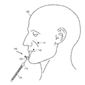
- the present invention relates to a lifting surgical instrument which is used to lift a tissue by moving a tissue layer under a skin layer in an upward direction or which is used to insert a thread into the skin in order to remove a wrinkle by moving a lower skin layer in an upward direction. More specifically, the present invention relates to a lifting surgical instrument having a branch point, which uses a sheath as a branch point in order to form a thread without a cog and a barb in a ring shape under the skin and to perform a lifting surgery.
- a plastic surgery is a generic term for surgical operations which are performed chiefly for the correction of a partially damaged or deformed part of a human body or for cosmetic treatment.
- surgical operations for cosmetic treatment have become commonplace.
- a surgical operation for anti-aging has been attracting attention.
- a face lifting operation has been attracting increasing attention.
- a long incision is directly made in the skin, a skin layer is dissected, a thread is directly inserted into a droopy subcutaneous tissue under direct vision (i.e., while the droopy subcutaneous tissue is being directly observed), and then the droopy subcutaneous tissue is lifted.
- the invasive method provides a desirable effect, but is disadvantageous in that the time required to perform the invasive method is relatively long, bleeding occurs during the process of directly making an incision, and surgical scars may be left.
- the minimally invasive method has been proposed to mitigate the above disadvantages.
- a thread with cogs or barbs is inserted under a skin layer, and a droopy subcutaneous tissue is lifted by using force attributable to the cogs or barbs.
- the minimally invasive method is advantageous in that the time required to perform the minimally invasive method is shorter than that required to perform the invasive method, surgical scars are small, and the amount of bleeding is small.
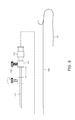
- One of the conventional lifting surgical instruments includes a sheath 10 , a needle 20 connected to a thread 30 , and the thread 30 . More specifically, referring to FIG. 1 , the sheath 10 , in which the front end thereof has an inclined surface and a through hole penetrates therethrough in a longitudinal direction, is inserted into the skin, the thread 30 is passed through the through hole of the sheath 10 , and the thread 30 is moved to the front end of the sheath 10 . Thereafter, when the sheath 10 is removed, the thread 30 is left in a subcutaneous tissue.
- the thread 30 includes cogs or barbs, the cogs or barbs have directionality, and the cogs or barbs provide fastening force in a direction opposite to the direction, in which the thread 30 has been inserted, when the thread 30 has been inserted into a subcutaneous tissue. Accordingly, when the thread 30 left in the subcutaneous tissue is pulled, the cogs or barbs are caught in the subcutaneous tissue, the droopy tissue is lifted by the fastening force generated by the cogs or barbs, and thus a wrinkle may be removed.
- a lifting surgery may be performed based on a principle identical to that of the above case by directly passing the needle 20 connected to the thread 30 through the skin without using the sheath 10 and inserting the thread 30 into a subcutaneous tissue.
- This conventional technology may cause problems as follows:
- the cogs or barbs of the thread 30 are formed on the sides of the thread 30 , have directionality, and are formed in a wing shape through partial cutting. Accordingly, sufficient fastening force may not be provided via the cogs or barbs due to the thinness of the thread 30 .
- the fastening force may be increased by increasing the thickness of the thread 30 .
- a patient may have the sensation of a foreign substance upon insertion into a skin tissue, thereby causing the patient discomfort.
- the fastening force may be increased by inserting a plurality of threads 30 into the skin, a plurality of insertion holes is thus required. Accordingly, a number of scars are left after a lifting surgery, thereby causing an aesthetic problem.
- the conventional technology becomes more problematic in that the sensation of a foreign substance attributable to the threads 30 may occur, the threads 30 may protrude, and inflammation may be caused by the threads 30 .
- the cogs or barbs of the thread 30 are disposed not only in the droopy subcutaneous tissue which a surgeon desires to lift, but also in another subcutaneous tissue, thereby causing a problem in that an unintentional lifting of another subcutaneous tissue may occur.
- the cogs or barbs may be damaged or lost when the thread 30 is linearly pulled. Accordingly, the skin and a subcutaneous tissue are unevenly lifted, thereby causing an effect different from an expected effect. Furthermore, due to the phenomenon of the traction of the periphery of a surgical site occurring after a surgery, the cogs or barbs may be damaged or lost when a patient moves a facial muscle, thereby causing a problem in that sufficient fastening force may not be provided.
- the ends of the cogs or barbs are sharp due to the structure of the cogs or barbs on the thread 30 , and thus a tissue may be damaged or a patient may suffer from pain.
- Patent document 1 Korean Patent Application Publication No. 10-2014-0092096 (published on Jul. 23, 2014)
- the present invention has been conceived to overcome the above-described problems, and an object of the present invention is to provide a lifting surgical instrument having a branch point, which uses a sheath as a branch point in order to form a thread without a cog and a barb in a ring shape under the skin and to perform a lifting surgery.
- a lifting surgical instrument having a branch point
- the lifting surgical instrument including a sheath
- the sheath includes: a probe part formed in the tubular shape in which a through hole penetrating in a longitudinal direction is formed, and configured such that the front end thereof may be inserted into the skin; and a body configured to extend from the rear end of the probe part, to have a diameter larger than that of the through hole of the probe part, to communicate with the inside of the through hole, and to include the sheath hole into which a needle may be inserted.
- a direction guidance portion configured to protrude from the inner surface of the probe part to the through hole is provided on the inner surface of the probe part, and the angle at which the needle travels is changed via the direction guidance portion when the needle passes through the through hole of the probe part.
- the lifting surgical instrument having a branch point may further include an indicator configured to extend the outer diameter of the probe part when the indicator is inserted over the outer surface of the probe part, to slide in the longitudinal direction of the probe part, and to be fastened to the probe part at a predetermined location, thereby being caught by an introduction hole in the skin so that the probe part can be located at a desired location under the skin when the probe part is inserted into the skin.
- the direction guidance portion of the lifting surgical instrument having a branch point according to the present invention may be provided at the front end of the probe part.
- the direction guidance portion may form a rising curve on the inner surface of the probe part, and may extend to one end of the probe part.
- the direction guidance portion of the lifting surgical instrument having a branch point according to the present invention may be formed to have a semicircular or semielliptical sectional shape.
- the indicator of the lifting surgical instrument having a branch point may include: an indicator body configured to include the insertion hole which penetrates the inner and outer surfaces thereof; and a location fastening member configured to be inserted into the insertion hole so that the indicator can be fastened to the probe part at the predetermined location.
- screw grooves may be formed in the inner surface of the insertion hole formed in the indicator body
- the location fastening member may include a bolt and be screwed into the insertion hole
- the indicator may be fastened to the probe part at the predetermined location when one end of the bolt inserted into the insertion hole comes in contact with the outer surface of the probe part.
- the indicator of the lifting surgical instrument having a branch point may include a body part and a cover part configured to be inserted over the body part.
- the body part may include a cylindrical base part and a screw part configured to extend from the base part and to include bolt threads, and screw grooves may be formed in the inner surface of the cover part.
- the cover part may be inserted over the screw part through screw coupling, and the diameter of the inner surface of the cover part in which the screw grooves are formed may be smaller than that of the screw part.
- the screw part may be tightened when the cover part is inserted over the screw part and coupled to the screw part.
- a marking point may be provided on the outer surface of the body part or cover part.
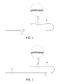
- FIG. 1 is a view showing an assembled lifting surgical instrument according to an embodiment of a conventional technology
- FIG. 2 is a view showing another assembled lifting surgical instrument according to another embodiment of the conventional technology
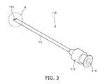
- FIG. 3 is a perspective view showing a sheath according to an embodiment of the present invention.
- FIGS. 4 a and 4 b are enlarged views of the probe part (i.e., portion A) shown in FIG. 3 ;
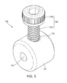
- FIG. 5 is a perspective view showing an indicator according to an embodiment of the present invention.
- FIG. 6 is a view showing the operations of a sheath shown in FIG. 3 and an indicator shown in FIG. 5 ;
- FIG. 7 is a perspective view showing a stylet according to an embodiment of the present invention.
- FIGS. 8 a and 8 b are views showing paths of a needle based on a direction guidance portion according to an embodiment of the present invention.
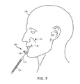
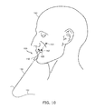
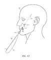
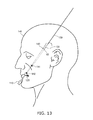
- FIGS. 9 to 13 are views showing a surgical method using a thread without a cog and a barb and a lifting surgical instrument having a branch point according to the present invention.
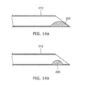
- FIGS. 14 a and 14 b are views showing direction guidance portions according to other embodiments of the present invention.
- FIG. 15 is a view showing an indicator according to another embodiment of the present invention.
- a lifting surgical instrument 100 is used to form a thread 131 without a cog and a barb in a ring shape under the skin and to perform a lifting surgery.
- the lifting surgical instrument 100 relates to a lifting surgical instrument having a branch point, which enables the front end of a sheath 110 to be disposed at a desired location in a subcutaneous tissue by using an indicator 120 and uses the sheath 110 as a branch point so that a thread 131 without a cog and a barb can be formed in a ring shape under the skin.
- the lifting surgical instrument 100 is a surgical instrument for a surgical method which has been newly conceived by the applicant of the present invention.
- the newly conceived surgical method is configured to form the thread 131 without a cog and a barb in a ring shape at a desired location within the tissue and to lift a droopy tissue, unlike the conventional lifting surgical methods configured to insert a thread with cogs or barbs into a subcutaneous tissue and to pull the thread.
- a needle is required to pass through a sheath twice in order to form a thread in a ring shape at a desired location within a tissue.
- a ring shape may not be formed at a desired location by simply passing a needle through a sheath twice because the traveling path of the needle within a subcutaneous tissue formed after passing through the sheath for the first time may overlap the traveling path of the needle within the subcutaneous tissue formed after passing through the sheath for the second time.
- the traveling paths of a needle are required to branch off from each other at a desired location in order to form a thread in a ring shape at a desired location.
- the lifting surgical instrument 100 includes a bump (i.e., a direction guidance portion 150 ) formed on the inner surface of the probe part 111 of the sheath 110 , and changes the angle of the direction in which the needle travels via the bump when the needle passes through the sheath 110 .
- a bump i.e., a direction guidance portion 150
- the lifting surgical instrument 100 includes the sheath 110 including the probe part 111 and a body 112 , an indicator 120 , and the direction guidance portion 150 .
- the sheath 110 including the probe part 111 and a body 112 , an indicator 120 , and the direction guidance portion 150 .
- FIG. 9 The entire lifting surgical instrument 100 of the present invention is shown, for example, in FIG. 9 , and FIG. 10 shows the lifting surgical instrument 100 from which some components are removed in order to explain functions of the needle 130 .
- the sheath 110 includes the probe part 111 and the body 112 .
- the probe part 111 is formed in a tubular shape in which a through hole 113 configured to penetrate the probe part 111 in a longitudinal direction is formed, and the front end of the probe part 111 has an inclined surface.
- a portion of the probe part 111 may be inserted into the skin through an introduction hole 142 after the introduction hole 142 has been formed in the surface of the skin via an injection needle or needle.
- the sectional shape of the front end of the probe part 111 forms an inclined cross section.
- the body 112 is connected to the rear end of the probe part 111 , and is expanded.
- the body 112 includes a sheath hole 114 configured to communicate with the through hole 113 disposed inside the probe part 111 , and the diameter of the sheath hole 114 is larger than that of the through hole 113 .
- the needle 130 is inserted through the sheath hole 114 .
- the needle 130 is easily inserted because the sheath hole 114 has a larger diameter than the through hole 113 .
- the inserted needle 130 is moved forward through the through hole 113 which communicates with the sheath hole 114 .
- the direction guidance portion 150 configured to protrude from the inner surface of the probe part 111 into the through hole 113 is provided on the inner surface of the probe part 111 .
- the direction guidance portion 150 changes the angle at which the needle 130 travels when the needle 130 passes through the through hole 113 of the probe part 111 , thereby changing the path of the needle 130 .
- the direction guidance portion 150 may be provided at the front end of the probe part 111 , the direction in which the needle 130 travels is changed at the front end of the probe part 111 via the direction guidance portion 150 , and then the needle 130 passes through the probe part 111 .
- the location of the direction guidance portion 150 is not limited thereto, but the direction guidance portion 150 may be formed at any one of various locations.
- the direction guidance portion 150 may be provided in the middle portion of the probe part 111 , in which case the direction in which the needle 130 travels may be changed in the middle portion of the probe part 111 .
- the direction guidance portion 150 may form a rising curve on the inner surface of the probe part 111 , and may extend to one end of the probe part 111 .
- the direction guidance portion 150 forms the rising curve, and thus the direction in which the needle 130 travels may be gradually changed along the rising curve.
- the shape of the direction guidance portion 150 is not limited thereto but the direction guidance portion 150 may be formed in any one of various shapes as long as these shapes change the direction in which the needle 130 travels.
- the indicator 120 is inserted over the outer surface of the probe part 111 , and extends the outer diameter of the probe part 111 .
- the indicator 120 may slide in the longitudinal direction of the probe part 111 , and may be fastened by tightening a location fastening member at a predetermined location on the probe part 111 .
- the predetermined location which is present on the probe part 111 and at which the indicator 120 is fastened is determined based on the location at which the front end of the probe part 111 is located within a subcutaneous tissue and the location of the introduction hole 142 through which the probe part 111 is inserted.
- the location (i.e., a lifting location 141 ) at which the front end of the probe part 111 is located is the location at which a surgeon intends to lift a droopy tissue or a subcutaneous tissue around a wrinkle.
- the outer diameter of the portion of the probe part 111 on which the indicator 120 has been disposed is extended at the predetermined location. Accordingly, when the probe part 111 is inserted into the skin, only the portion of the probe part 111 before the indicator 120 is inserted, and the indicator 120 is caught by the introduction hole 142 .
- the indicator 120 may include the indicator body 121 and the location fastening member.
- the indicator body 121 is formed in a cylindrical shape, and has an upper surface, a lower surface, and an outer surface.
- a body hole configured to penetrate the center of the upper surface and the center of the lower surface is formed in the indicator body 121 , and the indicator body 121 includes an insertion hole 123 configured to penetrate the outer surface of the indicator body 121 and the inner surface of the indicator body 121 (i.e., the inner surface of the body hole).
- the location fastening member is inserted into the insertion hole 123 , and fastens the indicator 120 to the probe part 111 at a predetermined location.
- bolt threads are formed on the inner surface of the insertion hole 123 configured to penetrate the outer surface of the indicator body 121 and the inner surface of the indicator body 121 (i.e., the inner surface of the body hole 124 ), and the location fastening member is composed of a bolt 122 . Accordingly, the bolt 122 is inserted into the indicator body 121 through screw coupling (in other words, the indicator body 121 functions as a nut).
- the bolt 122 which is a location fastening member, is screwed into the insertion hole 123 .
- the bolt 122 which is a location fastening member, is sufficiently tightened such that one end of the bolt 122 comes in contact with the outer surface of the probe part 111 inserted into the body hole.
- frictional force is generated, and thus the indicator 120 is fastened and prevented from sliding.
- the bolt 122 includes the bolt thread portion 122 b configured such that bolt threads are formed thereon, and a bolt head 122 a configured to be disposed on the bolt thread portion 122 b and to have an increased outer diameter. Grooves are formed in the outer surface of the bolt head 122 a in a circumferential direction at predetermined intervals, and the grooves prevent the bolt 122 from slipping when a surgeon tightens the bolt 122 .
- the reference numeral “ 124 ” designates a stylet 124 .
- the stylet 124 is inserted into the through hole 113 of the probe part 111 , and is inserted into the skin along with the probe part 111 when the probe part 111 is inserted into the skin, thereby preventing the through hole 113 from being filled with a subcutaneous tissue.
- the diameter of the stylet 124 is slightly smaller than the inner diameter of the probe part 111 so that the stylet 124 is inserted into the through hole 113 inside the probe part 111 , and the stylet 124 is formed in a bar shape.
- the through hole 113 may be filled with a part of a subcutaneous tissue when the probe part 111 is inserted into the skin, and may cause damage to a tissue or blood vessel. Accordingly, the probe part 111 is inserted into the skin after the stylet 124 has been coupled to the through hole 113 inside the probe part 111 .
- the stylet 124 is coupled to the probe part 111 and inserted into the skin along with the probe part 111 , and thus a grip is preferably mounted on the rear end of the stylet 124 in order to transfer force to the probe part 111 and the stylet 124 .
- the overall diameter of the needle 130 from one end thereof to the other end thereof is smaller than that of the through hole 113 of the probe part 111 so that the needle 130 can pass through the through hole 113 of the probe part 111 and the lifting location 141 , can pierce through a subcutaneous tissue, and can exit from the skin.
- the length of the needle 130 is longer than that of the sheath 110 , and an eye is formed at the rear end of the needle 130 so that the thread 131 without a cog and a barb is inserted into the eye.
- the needle 130 Since the length of the needle 130 is longer than that of the sheath 110 , the needle 130 pierces through a subcutaneous tissue, and exits from the skin after passing through the sheath 110 .
- the needle 130 cannot pass through the sheath 110 , cannot pierce through a subcutaneous tissue, and cannot exit from the skin. Accordingly, the length of the needle 130 is required to be sufficiently longer than that of the sheath 110 .
- a part of the thread 131 without a cog and a barb is inserted into the eye of the needle 130 , and exits from the skin along with the needle 130 when the needle 130 passes through the through hole 113 of the probe part 111 and the lifting location 141 , pierces through a subcutaneous tissue, and exits from the skin.
- the thread 131 without a cog and a barb passes through the sheath 110 and a subcutaneous tissue twice in the state in which the front and rear parts of the thread 131 without a cog and a barb have been individually inserted into the eye of the needle 130 .
- the indicator 120 is inserted over the probe part 111 , is slid along the probe part 111 , and is then fastened at a predetermined location.
- the predetermined location is changed based on the depth to which the probe part 111 is inserted, and the depth to which the probe part 111 is inserted for a lifting surgery is variable.
- the introduction hole 142 through which the front end of the probe part 111 is inserted is required to be formed at the location which makes surgical scars preferably less visible and at which a surgery be easily performed.
- the location of the probe part 111 may be changed based on the location of a droopy subcutaneous tissue or wrinkle required to be lifted.
- the size of the face varies from person to person, and thus the distance between the introduction hole 142 through which the probe part 111 is inserted and the lifting location 141 at which a droopy tissue is required to be lifted varies. Accordingly, the depth to which the probe part 111 is inserted varies.
- a second thread may be also inserted for a surgery after a first thread has been inserted.
- the depth to which the probe part 111 is inserted may be changed, and the changed depth may be controlled via the indicator 120 .
- the path of the needle 130 traveling in a subcutaneous tissue after the front part of the thread 131 without a cog and a barb has been inserted into the needle 130 and the needle 130 has exited from the front end of the probe part 111 may be made different from the path of the needle 130 traveling in a subcutaneous tissue after the rear part of the thread 131 without a cog and a barb has been inserted into the needle 130 and the needle 130 has exited from the front end of the probe part 111 .
- the lifting surgical instrument according to the present invention is used for a lifting surgery in which the thread 131 without a cog and a barb is formed in a ring shape under the skin, and thus the paths of the needle 130 configured to be inserted twice and travel in subcutaneous tissues are required to be made different in order to form the thread 131 without a cog and a barb in a ring shape.
- the direction guidance portion 150 makes the paths of the needle 130 , passing through the direction guidance portion 150 twice, different, thereby providing the effect of preventing the above-described problems from occurring ( FIGS. 8 a and 8 b exaggeratedly illustrate the process in which the needle 130 is curved and the paths of the needle 130 are changed, and thus the actual curves of the needle 130 may be smaller than those illustrated in FIGS. 8 a and 8 b . Furthermore, as the needle 130 travels farther, the paths of the needle 130 having passed through the front end of the probe part 111 may be more separated from each other than the initial linear path of the needle 130 .).
- the lifting surgical instrument 100 is a lifting surgical instrument used to perform the lifting surgical method which is newly conceived by the applicant of the present invention and in which a lifting surgery is performed using the thread 131 without a cog and a barb, unlike the conventional lifting surgical methods in which a thread with cogs or barbs is caught in a subcutaneous tissue and is then pulled.
- the new surgical method originally developed by the applicant of the present invention is configured to hold a subcutaneous tissue around a droopy wrinkle with the thread 131 without a cog and a barb in a ring shape and to directly pull the droopy subcutaneous tissue, thereby removing the wrinkle through lifting.
- another feature of the new surgical method resides in that the direction in which a thread is inserted is opposite to that of the conventional lifting surgical methods using a thread.
- a thread is inserted in a downward direction
- a thread is inserted in an upward direction.
- the lifting location 141 at which a droopy tissue or wrinkle is present is determined, and the location of the introduction hole 142 into which the probe part 111 is inserted is determined such that the front end of the probe part 111 is located at the lifting location 141 .
- the indicator 120 is inserted over the probe part 111 , and is fastened to the probe part 111 at a predetermined location by considering the distance between the lifting location 141 and the location of the introduction hole 142 .
- the probe part 111 in the state in which the stylet 124 has been coupled thereto and the indicator 120 has been fastened thereto is inserted into the skin, and then the probe part 111 is moved forward to the location at which the indicator 120 is caught by the introduction hole 142 . In this case, the front end of the probe part 111 is located at the lifting location 141 , and then the mounted stylet 124 is removed.
- the front part of the thread 131 without a cog and a barb is inserted into the eye of the needle 130 , and the needle 130 is moved forward such that the needle 130 passes through the through hole 113 of the probe part 111 and the lifting location 141 , pierces through a subcutaneous tissue, and exits from the skin through an exit 143 (in which case the exit 143 through which the needle 130 exits from the skin is preferably located in a region (mostly a scalp region) which makes surgical scars less visible).
- the direction in which the needle 130 travels is changed into a predetermined direction via the direction guidance portion 150 , and the needle 130 is inserted into a subcutaneous tissue.
- the needle 130 is separated from the thread 131 without a cog and a barb, and the rear part of the thread 131 without a cog and a barb is inserted into the eye of the needle 130 .
- the sheath 110 is rotated through 180 degrees, and the needle 130 is moved forward such that the needle 130 passes through the through hole 113 of the probe part 111 and the lifting location 141 once again, pierces through a subcutaneous tissue, and exits from the skin through the exit 143 .
- the reason why the sheath 110 is rotated through 180 degrees is to change the location of the direction guidance portion 150 and thus make the path of needle 130 , into which the rear part of the thread 131 without a cog and a barb has been inserted, different from the path of needle 130 into which the front part of the thread 131 without a cog and a barb has been inserted (i.e., to make the paths of the needle 130 , traveling in subcutaneous tissues after the front end of the probe part 111 through which the needle 130 has passed twice, different).
- the sheath 110 when the sheath 110 is rotated through 180 degrees, the location of the direction guidance portion 150 disposed inside the probe part 111 is changed, and thus the path of the needle 130 is also changed.
- the sheath 110 is preferably rotated through 180 degrees, but the sheath 110 may be rotated through an angle other than 180 degrees if necessary.
- the angle through which the sheath 110 is rotated may be checked via the bolt 122 of the indicator 120 because the bolt 122 protrudes from the indicator 120 .
- the location of the bolt 122 is aligned with the location of the direction guidance portion 150 of the probe part 111 , and then the indicator 120 is fastened.
- the location of the direction guidance portion 150 may be estimated via the bolt 122 , and the path of the needle 130 may be controlled.
- the angle through which the sheath 110 is rotated may be checked via a mark, provided on the indicator 120 , or the like other than the bolt 122 .
- the angle through which the sheath 110 is rotated may be checked via the insertion hole 123 provided in the indicator 120 .
- a space disposed within the probe part 111 and configured to extend to the front end of the probe part 111 is empty because the probe part 111 is formed in a tubular shape, but a space disposed after the front end of the probe part 111 and configured to extend to the location at which the needle 130 exits from the skin is filled with a subcutaneous tissue.
- the part of the thread 131 without a cog and a barb which is disposed along the path of the needle 130 which has been threaded with the front part of the thread 131 without a cog and a barb and then passed through subcutaneous tissues
- the part of the thread 131 without a cog and a barb which is disposed along the path of the needle 130 which has been threaded with the rear part of the thread 131 and then passed through subcutaneous tissues
- the two parts of the thread 131 are connected to each other at the lifting location 141 within a subcutaneous tissue, and form a ring shape.
- the paths of the needle 130 passed through the direction guidance portion 150 twice do not overlap each other via the direction guidance portion 150 , and thus the thread 131 without a cog and a barb can be easily formed in a ring shape under the skin.
- a surgical procedure according to the above-described surgical method may be additionally performed.
- the depth to which the probe part 111 is inserted may be changed by a medical doctor performing the surgical procedure, as desired.
- the change is made by changing the location of the indicator 120 .
- the location of the front end of the sheath 110 inserted into a subcutaneous tissue is not changed during the surgery.
- the reason for this is that the location of the front end of the sheath 110 is directly related to the lifting location 141 at which lifting is desired by a surgeon. Accordingly, when the location of the front end of the sheath 110 is changed, the lifting location 141 is changed, and thus the lifting location 141 is disposed at a location other than a location desired by the surgeon. For this reason, it is important that the location of the front end of the sheath 110 is not changed during the surgery.
- the sheath 110 may be moved along with the needle 130 due to the frictional resistance between the needle 130 and the sheath 110 , and thus the location of the front end of the sheath 110 may be changed under the skin.
- the needle 130 is pulled away by pulling the needle 130 after the needle 130 has pierced through a subcutaneous tissue and has exited from the skin, frictional resistance may be generated between the needle 130 and the sheath 110 , and thus the location of the front end of the sheath 110 may be changed under the skin.
- a location other than a location desired by the surgeon becomes the lifting location 141 .
- the indicator 120 When the indicator 120 according to the present invention is employed, only the part of the sheath 110 extending to the portion thereof on which the indicator 120 is disposed may be inserted into the skin. Accordingly, even when frictional resistance is generated between the needle 130 and the sheath 110 , the sheath 110 does not penetrate into the skin any farther due to the indicator 120 , and thus the location of the front end of the sheath 110 is not changed under the skin. Accordingly, the lifting location 141 desired by the surgeon can be prevented from being changed.
- the needle 130 is required to pass through the sheath 110 twice in order to perform the new surgical method in which the thread 131 without a cog and a barb is inserted into the skin and is formed in a ring shape under the skin by using the needle 130 and the sheath 110 , unlike in the conventional surgical methods using a thread 30 with cogs or barbs.
- the rear part of the thread 131 is required to be inserted into the eye of the needle 130 and the needle 130 is required to pass through the sheath 110 again.
- the location of the front end of the sheath 110 may be checked.
- the indicator 120 extends the outer diameter of the sheath 110 , and thus the location of the front end of the sheath 110 is not changed.
- the location of the front end of the sheath 110 inserted into the skin may be changed due to frictional resistance when the long needle 130 passes through the sheath 110 .
- the indicator 120 is employed. Accordingly, the location of the indicator 120 is checked when the needle 130 passes through the sheath 110 for the first time, the sheath 110 is located at the location at which the indicator 120 is present before the needle 130 passes through the sheath 110 for the second time, and then the needle 130 is moved forward such that the needle 130 passes through the sheath 110 for the second time.
- the specific location, at which the front end of the sheath 110 is located when the needle 130 passes through the sheath 110 for the first time becomes identical to the location at which the front end of the sheath 110 is located when the needle 130 passes through the sheath 110 for the second time. Therefore, even when the needle 130 passes through the sheath 110 twice, the location of the front end of the sheath 110 is not changed.
- the lifting location 141 is required to be accurately adjusted during the performance of the new lifting surgical method in which the thread 131 without a cog and a barb is inserted and formed in a ring shape by using the needle 130 and the sheath 110 .
- the lifting location 141 is required to be accurately adjusted during the actual performance of the new lifting surgical method.
- the depth to which the sheath 110 is inserted may be required to be accurately and repeatedly adjusted during the performance (in other words, there is a case in which lifting is required to be performed at a plurality of lifting locations 141 rather than a single lifting location 141 ).
- the lifting location 141 may be changed by changing the location at which the sheath 110 is inserted into the skin.
- the location at which the sheath 110 has been initially inserted into the skin may not be compared with the location at which the sheath 110 is intended to be inserted into the skin.
- the location at which the sheath 110 has been initially inserted into the skin may be determined, and thus the locations at which the sheath 110 is inserted may be accurately adjusted when the sheath 110 is repeatedly inserted.
- the location at which the sheath 110 is inserted is moved within a range from 2 to 3 mm, and thus the lifting location 141 may be accurately adjusted within a range from 2 to 3 mm (for this purpose, markings on the probe part 111 of the sheath 110 are preferably used). Accordingly, when the indicator 120 is employed, an advantage arises in that the new surgical method using the lifting surgical instrument according to the present invention may be more accurately performed.
- the needle 130 passes through the through hole 113 of the probe part 111 and pierces through subcutaneous tissues twice. If the needle 130 travels along the same path or partially overlapping paths when passing through the front end of the probe part 111 and then piercing through a subcutaneous tissue or subcutaneous tissues twice, the thread 131 without a cog and a barb may not be formed in a ring shape. Even when the thread 131 is formed in a ring shape, the thread 131 starts to be curved at a location other than the location of the front end of the probe part 111 , and thus a tissue may not be lifted at a location desired by a surgeon.
- the direction guidance portion 150 is provided on the inner surface of the probe part 111 , and thus the path of the needle 130 may be changed when the needle 130 passes through the front end of the probe part 111 , thereby easily forming the thread 131 without a cog and a barb in a ring shape under the skin.
- the most conventional surgical methods using a thread are required to catch and lift a tissue by using a single strand of thread formed in a linear shape, and thus cogs or barbs are required to be formed on the surface of a thread.
- the fastening force of cogs or barbs is weak due to the thinness of a thread, and a droopy tissue is unevenly lifted due to damage to the cogs or barbs or loss of the cogs or barbs.
- the cogs or barbs are formed on the most part of the thread, and thus the part which is not desired by a surgeon may be also influenced.
- the surgical method using the surgical instrument according to the present invention is advantageous in that there is no concern about the uneven lifting of a droopy tissue because the surgical instrument does not use any cog or barb, in that sufficient fastening force may be applied by directly holding a tissue with the thread 131 at the target lifting location 141 and pulling the thread 131 , and in that only a desired part may be selectively lifted.
- a skin tissue may be damaged by the sharp cogs or barbs, and thus the cogs or barbs may cause a patient pain.
- the surgical method using the surgical instrument according to the present invention is advantageous in that a skin tissue is not damaged by cogs or barbs and a patient does not suffer from a pain attributable to cogs or barbs.
- the probe part 111 may be located at a desired location under the skin by using the indicator 120 according to the present invention, and thus the lifting location 141 at which a subcutaneous tissue around a droopy wrinkle is intended to be lifted is prevented from being changed during a surgery, thereby being advantageous in that a lifting surgery may be performed using the thread 131 without a cog and a barb.
- a subcutaneous tissue other than a droopy subcutaneous tissue which a surgeon desires to lift may be influenced by the cogs or barbs.
- the lifting surgical instrument having a branch point according to the present invention holds a subcutaneous tissue with the thread 131 without a cog and a barb in a ring shape, thereby being advantageous in that only a subcutaneous tissue which a surgeon desires to lift may be selectively lifted.
- the direction guidance portion 150 is provided on the probe part 111 of the sheath 110 , thereby being advantageous in that the thread 131 may be easily formed in a ring shape under the skin.
- a direction guidance portion 250 may be formed to have a semicircular sectional shape.
- the semicircular direction guidance portion 250 may move a needle along the front arc of the semicircular sectional shape, and the direction in which the needle travels may be easily changed via the front arc of the semicircular sectional shape.
- the sectional shape of the direction guidance portion 250 is not limited to the semicircular sectional shape, but the direction guidance portion 250 may be formed to have a semielliptical sectional shape.
- the semicircular direction guidance portion 250 may be provided at the front end of a probe part, but the location of the semicircular direction guidance portion 250 is not limited thereto. Referring to FIG.
- the semicircular direction guidance portion 250 may be provided in the middle portion of a probe part.
- the direction in which a needle travels is changed after the middle portion of the probe part.
- the direction guidance portion according to the present invention may be formed in any one of various shapes as long as these shapes enable the direction in which a needle travels to be changed.
- the indicator 320 may include a body part 321 and a cover part 322 configured to be inserted over the body part 321 .
- the body part 321 and the cover part 322 may include the respective holes into which a sheath 310 is inserted, and the indicator 320 is fastened to the sheath 310 when the cover part 322 is coupled to the body part 321 .
- the body part 321 includes a base part 323 formed in a cylindrical shape and a bolt part 324 configured to extend from the base part 323 and to include bolt threads 326 .
- the bolt part 324 has a diameter smaller than that of the base part 323 , and extends from the base part 323 .
- a connection part 325 may be disposed between the base part 323 and the bolt part 324 . The diameter of the connection part 325 is smaller than that of the base part 323 , and is larger than that of the bolt part 324 .
- Screw grooves are formed in the inside of the cover part 322 .
- the bolt part 324 of the body part 321 is screwed into the cover part 322 , and the bolt threads 326 of the bolt part 324 and the screw grooves of the cover part 322 engage with each other through screw coupling.
- the diameter of the inside of the cover part 322 in which the screw grooves are formed is smaller than that of the bolt part 324 . Since the diameter of the inside of the cover part 322 in which the screw grooves are formed is smaller than that of the bolt part 324 , the cover part 322 may tighten the bolt part 324 when the bolt part 324 is completely screwed into the cover part 322 .
- the body part 321 and the cover part 322 may include the respective holes into which the sheath 310 is inserted, and thus the base part 323 and the bolt part 324 also include the respective holes into which the sheath 310 is inserted.
- the tightening of the bolt part 324 indicates that the hole of the bolt part 324 into which the sheath 310 is inserted is tightened via the screw grooves formed inside the cover part 322 .
- the cover part 322 is provisionally coupled to the body part 321 , and the indicator 320 is inserted over the sheath 310 .
- the indicator 320 is disposed at the location at which the indicator 320 needs to be fastened to the sheath 310 , and the cover part 322 is completely coupled to the body part 321 .
- the indicator 320 may be slid along the sheath 310 because the bolt part 324 is not tightened by the screw grooves formed in the inside of the cover part 322 yet.
- the indicator 320 is not slid along the sheath 310 and fastened to the sheath 310 because the screw grooves formed in the inside of the cover part 322 tighten the bolt part 324 .
- the cover part 322 is loosened (so as to be in the provisional coupling state), and then the indicator 320 is slid.
- the bolt part 324 may include grooves 327 extending in a direction perpendicular to that of the bolt threads 326 .
- the diameter of the bolt part 324 is larger than that of the inside of the cover part 322 in which the screw grooves are formed, and thus it may be slightly difficult to insert the bolt part 324 into the cover part 322 .
- the grooves 327 formed in the bolt part 324 provide the spaces which enable the bolt part 324 to be deformed. Accordingly, when the bolt part 324 is inserted into the cover part 322 , the bolt part 324 may be partially deformed via the grooves 327 , and thus the bolt part 324 may be easily inserted into the cover part 322 .
- a marking point 328 may be provided on the outer surface of the body part 321 or cover part 322 .
- the direction guidance portion is provided on the probe part 311 of the sheath 310 , and the location of the direction guidance portion is changed by rotating the sheath 310 so that the path of a needle is changed during a surgery.
- the marking point 328 is provided in order to determine the angle of the rotation of the sheath 310 .
- the indicator 320 When the indicator 320 is fastened to the sheath 310 , the indicator 320 is fastened in the state in which the marking point 328 provided on the indicator 320 is aligned with the direction guidance portion of the sheath 310 . When the indicator 320 has been fastened to the sheath 310 , the indicator 320 is rotated along with the sheath 310 , and thus the angle of the rotation of the sheath 310 may be determined via the marking point 328 provided on the indicator 320 .
- the marking point 328 may be provided on the body part 321 or cover part 322 , and may be provided on any one of various regions on the indicator 320 as long as these regions are visible to the naked eye. Furthermore, the shape of the marking point 328 may be formed in the shape of a point, but the shape of the marking point 328 is not specifically limited to the shape of a point. It will be apparent that the shape of the marking point 328 may be any one of various shapes as long as these shapes are visible to the naked eye.
- the lifting surgical instrument according to the present invention has been described above with reference to various embodiments.
- the lifting surgical instrument according to the present invention is intended to be applied to the new surgical method in which the thread 131 without a cog and a barb is formed in a ring shape and a droopy tissue is lifted.
- the new surgical method and the gist of the present invention will be described below in brief.
- a droopy subcutaneous tissue is held and lifted using a thread without a cog and a barb.
- a long incision is directly made in the skin, a tissue is dissected, and a thread is directly caught in a droopy tissue under direct vision, and then the droopy tissue is lifted.
- the conventional surgical method is problematic in that bleeding occurs during the process of directly making the incision in the skin and surgical scars may be left.
- the applicant of the present invention has conceived the new surgical method in which a droopy tissue is directly held with a thread without a cog and a barb in a ring shape without making an incision in the skin and the droopy tissue is lifted, unlike in the conventional surgical method in which a long incision is directly made in the skin and a tissue is dissected.
- the sheath 110 , the indicator 120 , the needle 130 , the stylet 124 , and the direction guidance portion 150 provided to the sheath 110 according to the present invention are required to be used.
- the introduction hole 142 is formed in the skin, and the front end of the sheath 110 is located around a droopy tissue by moving the sheath 110 forward through the introduction hole 142 .
- the needle 130 is inserted twice in the state of having been threaded with the thread 131 without a cog and a barb
- the thread 131 without a cog and a barb is formed in the ring shape with which the droopy tissue is held.
- the thread 131 without a cog and a barb is pulled, the droopy tissue is lifted.
- the sheath 110 functions as a branch point, at which the thread 131 without a cog and a barb is curved, in order to form the thread 131 without a cog and a barb in a ring shape.
- the direction guidance portion 150 provided to the probe part 111 makes different the paths of the needle 130 , passing through the direction guidance portion 150 and traveling in subcutaneous tissues after the front end of the probe part 111 twice, thereby preventing the paths of the needle 130 from overlapping each other. Accordingly, the thread 131 without a cog and a barb, passing through the direction guidance portion 150 along with the needle 130 , may be easily formed in a ring shape under the skin.
- the indicator 120 according to the present invention has been conceived in order to fasten the sheath 110 and to accurately control a depth and a distance related to the sheath 110 .
- the lifting surgical instrument according to the present invention has been described above with reference to various embodiments, the lifting surgical instrument is not limited thereto.
- the lifting surgical instrument according to the present invention may be used to remove a droopy wrinkle of a face, and it will be apparent that the lifting surgical instrument according to the present invention may be used to lift droopy tissues of various body parts, such as a chest, a neck, a hip, and the like, or may be used to remove wrinkles in the various body parts.
- the usage of the sheath according to the present invention, to which the direction guidance portion is provided is not limited to usage for the lifting surgical instrument, and it will be apparent that the sheath to which the direction guidance portion is provided according to the present invention may be used in the various fields in which the path of a needle is changed by changing the direction in which the needle travels.
- the lifting surgical instrument having a branch point enables a lifting surgery to be performed by directly holding a droopy subcutaneous tissue with the thread without a cog and a barb in a ring shape, thereby being advantageous in that a decrease in fastening force attributable to damage to cogs or barbs or loss of the cogs or barbs is absent because the lifting surgical instrument does not use the method in which lifting is performed via a thread with cogs or barbs.
- a tissue other than a droopy subcutaneous tissue which a surgeon desires to lift may be influenced by the cogs or barbs.
- the lifting surgical instrument having a branch point according to the present invention holds a subcutaneous tissue with the thread without a cog and a barb in a ring shape, thereby being advantageous in that only the tissue which a surgeon desires to lift is selectively lifted.
- the direction guidance portion is provided to the probe part of the sheath, thereby being advantageous in that a ring shape may be easily formed under the skin.
- the lifting surgical instrument having a branch point is advantageous in that the front end of the sheath may be located at a desired location within a droopy, wrinkled skin by using the indicator and in that a wrinkle removal and lifting surgery may be performed by moving a subcutaneous tissue in an upward or desired direction via the thread without a cog and a barb.
Landscapes
- Health & Medical Sciences (AREA)
- Life Sciences & Earth Sciences (AREA)
- Surgery (AREA)
- General Health & Medical Sciences (AREA)
- Public Health (AREA)
- Biomedical Technology (AREA)
- Heart & Thoracic Surgery (AREA)
- Veterinary Medicine (AREA)
- Engineering & Computer Science (AREA)
- Animal Behavior & Ethology (AREA)
- Molecular Biology (AREA)
- Nuclear Medicine, Radiotherapy & Molecular Imaging (AREA)
- Medical Informatics (AREA)
- Pathology (AREA)
- Oral & Maxillofacial Surgery (AREA)
- Cardiology (AREA)
- Transplantation (AREA)
- Vascular Medicine (AREA)
- Gastroenterology & Hepatology (AREA)
- Dermatology (AREA)
- Surgical Instruments (AREA)
Abstract
Description
- The present invention relates to a lifting surgical instrument which is used to lift a tissue by moving a tissue layer under a skin layer in an upward direction or which is used to insert a thread into the skin in order to remove a wrinkle by moving a lower skin layer in an upward direction. More specifically, the present invention relates to a lifting surgical instrument having a branch point, which uses a sheath as a branch point in order to form a thread without a cog and a barb in a ring shape under the skin and to perform a lifting surgery.
- Generally, a plastic surgery is a generic term for surgical operations which are performed chiefly for the correction of a partially damaged or deformed part of a human body or for cosmetic treatment. Recently, surgical operations for cosmetic treatment have become commonplace. Among the surgical operations for cosmetic treatment, a surgical operation for anti-aging has been attracting attention. In particular, a face lifting operation has been attracting increasing attention.
- As a person ages, in other words, as an aging process proceeds over time, the skin and various layers under the skin droop downward due to gravity, and thus the appearance of a face becomes aged. Basically, there are two types of surgical methods which are performed in order to alter this aged appearance so as to provide a more youthful appearance. One is an invasive method in which a relatively long incision is made in the skin, and the other is a minimally invasive method which uses a thread.
- In the invasive method in which an incision is made, a long incision is directly made in the skin, a skin layer is dissected, a thread is directly inserted into a droopy subcutaneous tissue under direct vision (i.e., while the droopy subcutaneous tissue is being directly observed), and then the droopy subcutaneous tissue is lifted. The invasive method provides a desirable effect, but is disadvantageous in that the time required to perform the invasive method is relatively long, bleeding occurs during the process of directly making an incision, and surgical scars may be left.
- The minimally invasive method has been proposed to mitigate the above disadvantages. In the minimally invasive method, a thread with cogs or barbs is inserted under a skin layer, and a droopy subcutaneous tissue is lifted by using force attributable to the cogs or barbs. The minimally invasive method is advantageous in that the time required to perform the minimally invasive method is shorter than that required to perform the invasive method, surgical scars are small, and the amount of bleeding is small.
- Conventional lifting surgical instruments used to perform the minimally invasive method will be described with reference to
FIGS. 1 and 2 . One of the conventional lifting surgical instruments includes asheath 10, aneedle 20 connected to athread 30, and thethread 30. More specifically, referring toFIG. 1 , thesheath 10, in which the front end thereof has an inclined surface and a through hole penetrates therethrough in a longitudinal direction, is inserted into the skin, thethread 30 is passed through the through hole of thesheath 10, and thethread 30 is moved to the front end of thesheath 10. Thereafter, when thesheath 10 is removed, thethread 30 is left in a subcutaneous tissue. - The
thread 30 includes cogs or barbs, the cogs or barbs have directionality, and the cogs or barbs provide fastening force in a direction opposite to the direction, in which thethread 30 has been inserted, when thethread 30 has been inserted into a subcutaneous tissue. Accordingly, when thethread 30 left in the subcutaneous tissue is pulled, the cogs or barbs are caught in the subcutaneous tissue, the droopy tissue is lifted by the fastening force generated by the cogs or barbs, and thus a wrinkle may be removed. - Furthermore, as shown in
FIG. 2 , a lifting surgery may be performed based on a principle identical to that of the above case by directly passing theneedle 20 connected to thethread 30 through the skin without using thesheath 10 and inserting thethread 30 into a subcutaneous tissue. - This conventional technology may cause problems as follows:
- First, the cogs or barbs of the
thread 30 are formed on the sides of thethread 30, have directionality, and are formed in a wing shape through partial cutting. Accordingly, sufficient fastening force may not be provided via the cogs or barbs due to the thinness of thethread 30. The fastening force may be increased by increasing the thickness of thethread 30. When thethread 30 is thick, a patient may have the sensation of a foreign substance upon insertion into a skin tissue, thereby causing the patient discomfort. Although the fastening force may be increased by inserting a plurality ofthreads 30 into the skin, a plurality of insertion holes is thus required. Accordingly, a number of scars are left after a lifting surgery, thereby causing an aesthetic problem. Furthermore, as the number ofthreads 30 increases, the conventional technology becomes more problematic in that the sensation of a foreign substance attributable to thethreads 30 may occur, thethreads 30 may protrude, and inflammation may be caused by thethreads 30. - Second, the cogs or barbs of the
thread 30 are disposed not only in the droopy subcutaneous tissue which a surgeon desires to lift, but also in another subcutaneous tissue, thereby causing a problem in that an unintentional lifting of another subcutaneous tissue may occur. - Third, the cogs or barbs may be damaged or lost when the
thread 30 is linearly pulled. Accordingly, the skin and a subcutaneous tissue are unevenly lifted, thereby causing an effect different from an expected effect. Furthermore, due to the phenomenon of the traction of the periphery of a surgical site occurring after a surgery, the cogs or barbs may be damaged or lost when a patient moves a facial muscle, thereby causing a problem in that sufficient fastening force may not be provided. - Fourth, the ends of the cogs or barbs are sharp due to the structure of the cogs or barbs on the
thread 30, and thus a tissue may be damaged or a patient may suffer from pain. - (Patent document 1) Korean Patent Application Publication No. 10-2014-0092096 (published on Jul. 23, 2014)
- The present invention has been conceived to overcome the above-described problems, and an object of the present invention is to provide a lifting surgical instrument having a branch point, which uses a sheath as a branch point in order to form a thread without a cog and a barb in a ring shape under the skin and to perform a lifting surgery.
- In order to achieve the above-described object, according to the present invention, there is provided a lifting surgical instrument having a branch point, the lifting surgical instrument including a sheath, wherein the sheath includes: a probe part formed in the tubular shape in which a through hole penetrating in a longitudinal direction is formed, and configured such that the front end thereof may be inserted into the skin; and a body configured to extend from the rear end of the probe part, to have a diameter larger than that of the through hole of the probe part, to communicate with the inside of the through hole, and to include the sheath hole into which a needle may be inserted. In this case, a direction guidance portion configured to protrude from the inner surface of the probe part to the through hole is provided on the inner surface of the probe part, and the angle at which the needle travels is changed via the direction guidance portion when the needle passes through the through hole of the probe part.
- The lifting surgical instrument having a branch point according to the present invention may further include an indicator configured to extend the outer diameter of the probe part when the indicator is inserted over the outer surface of the probe part, to slide in the longitudinal direction of the probe part, and to be fastened to the probe part at a predetermined location, thereby being caught by an introduction hole in the skin so that the probe part can be located at a desired location under the skin when the probe part is inserted into the skin.
- The direction guidance portion of the lifting surgical instrument having a branch point according to the present invention may be provided at the front end of the probe part. The direction guidance portion may form a rising curve on the inner surface of the probe part, and may extend to one end of the probe part. The direction guidance portion of the lifting surgical instrument having a branch point according to the present invention may be formed to have a semicircular or semielliptical sectional shape.
- The indicator of the lifting surgical instrument having a branch point according to the present invention may include: an indicator body configured to include the insertion hole which penetrates the inner and outer surfaces thereof; and a location fastening member configured to be inserted into the insertion hole so that the indicator can be fastened to the probe part at the predetermined location. In this case, screw grooves may be formed in the inner surface of the insertion hole formed in the indicator body, the location fastening member may include a bolt and be screwed into the insertion hole, and the indicator may be fastened to the probe part at the predetermined location when one end of the bolt inserted into the insertion hole comes in contact with the outer surface of the probe part.
- The indicator of the lifting surgical instrument having a branch point according to the present invention may include a body part and a cover part configured to be inserted over the body part. In this case, the body part may include a cylindrical base part and a screw part configured to extend from the base part and to include bolt threads, and screw grooves may be formed in the inner surface of the cover part. The cover part may be inserted over the screw part through screw coupling, and the diameter of the inner surface of the cover part in which the screw grooves are formed may be smaller than that of the screw part. The screw part may be tightened when the cover part is inserted over the screw part and coupled to the screw part. A marking point may be provided on the outer surface of the body part or cover part.
- The above and other objects, features and advantages of the present invention will be more clearly understood from the following detailed description taken in conjunction with the accompanying drawings, in which:
-
FIG. 1 is a view showing an assembled lifting surgical instrument according to an embodiment of a conventional technology; -
FIG. 2 is a view showing another assembled lifting surgical instrument according to another embodiment of the conventional technology; -
FIG. 3 is a perspective view showing a sheath according to an embodiment of the present invention; -
FIGS. 4a and 4b are enlarged views of the probe part (i.e., portion A) shown inFIG. 3 ; -
FIG. 5 is a perspective view showing an indicator according to an embodiment of the present invention; -
FIG. 6 is a view showing the operations of a sheath shown inFIG. 3 and an indicator shown inFIG. 5 ; -
FIG. 7 is a perspective view showing a stylet according to an embodiment of the present invention; -
FIGS. 8a and 8b are views showing paths of a needle based on a direction guidance portion according to an embodiment of the present invention; -
FIGS. 9 to 13 are views showing a surgical method using a thread without a cog and a barb and a lifting surgical instrument having a branch point according to the present invention; -
FIGS. 14a and 14b are views showing direction guidance portions according to other embodiments of the present invention; and -
FIG. 15 is a view showing an indicator according to another embodiment of the present invention. - A lifting
surgical instrument 100 according to the present invention is used to form athread 131 without a cog and a barb in a ring shape under the skin and to perform a lifting surgery. The liftingsurgical instrument 100 relates to a lifting surgical instrument having a branch point, which enables the front end of asheath 110 to be disposed at a desired location in a subcutaneous tissue by using anindicator 120 and uses thesheath 110 as a branch point so that athread 131 without a cog and a barb can be formed in a ring shape under the skin. - The lifting
surgical instrument 100 according to the present invention is a surgical instrument for a surgical method which has been newly conceived by the applicant of the present invention. The newly conceived surgical method is configured to form thethread 131 without a cog and a barb in a ring shape at a desired location within the tissue and to lift a droopy tissue, unlike the conventional lifting surgical methods configured to insert a thread with cogs or barbs into a subcutaneous tissue and to pull the thread. - A needle is required to pass through a sheath twice in order to form a thread in a ring shape at a desired location within a tissue. Meanwhile, a ring shape may not be formed at a desired location by simply passing a needle through a sheath twice because the traveling path of the needle within a subcutaneous tissue formed after passing through the sheath for the first time may overlap the traveling path of the needle within the subcutaneous tissue formed after passing through the sheath for the second time. Accordingly, the traveling paths of a needle are required to branch off from each other at a desired location in order to form a thread in a ring shape at a desired location. In order to form an accurate branch point for a needle, the lifting
surgical instrument 100 according to the present invention includes a bump (i.e., a direction guidance portion 150) formed on the inner surface of theprobe part 111 of thesheath 110, and changes the angle of the direction in which the needle travels via the bump when the needle passes through thesheath 110. - The lifting
surgical instrument 100 according to the present invention includes thesheath 110 including theprobe part 111 and abody 112, anindicator 120, and thedirection guidance portion 150. A preferred embodiment of the present invention will be described in detail with reference to the accompanying drawings below. - The entire lifting
surgical instrument 100 of the present invention is shown, for example, inFIG. 9 , andFIG. 10 shows the liftingsurgical instrument 100 from which some components are removed in order to explain functions of theneedle 130. - Referring to
FIG. 3 , thesheath 110 includes theprobe part 111 and thebody 112. Theprobe part 111 is formed in a tubular shape in which a throughhole 113 configured to penetrate theprobe part 111 in a longitudinal direction is formed, and the front end of theprobe part 111 has an inclined surface. A portion of theprobe part 111 may be inserted into the skin through anintroduction hole 142 after theintroduction hole 142 has been formed in the surface of the skin via an injection needle or needle. The sectional shape of the front end of theprobe part 111 forms an inclined cross section. When theprobe part 111 has been inserted into the skin, aneedle 130 to which a thread has been coupled passes through the throughhole 113 which penetrates the inside of theprobe part 111. - The
body 112 is connected to the rear end of theprobe part 111, and is expanded. Thebody 112 includes asheath hole 114 configured to communicate with the throughhole 113 disposed inside theprobe part 111, and the diameter of thesheath hole 114 is larger than that of the throughhole 113. Theneedle 130 is inserted through thesheath hole 114. Theneedle 130 is easily inserted because thesheath hole 114 has a larger diameter than the throughhole 113. The insertedneedle 130 is moved forward through the throughhole 113 which communicates with thesheath hole 114. - The
direction guidance portion 150 configured to protrude from the inner surface of theprobe part 111 into the throughhole 113 is provided on the inner surface of theprobe part 111. - The
direction guidance portion 150 changes the angle at which theneedle 130 travels when theneedle 130 passes through the throughhole 113 of theprobe part 111, thereby changing the path of theneedle 130. Referring toFIGS. 4a and 4b , thedirection guidance portion 150 may be provided at the front end of theprobe part 111, the direction in which theneedle 130 travels is changed at the front end of theprobe part 111 via thedirection guidance portion 150, and then theneedle 130 passes through theprobe part 111. The location of thedirection guidance portion 150 is not limited thereto, but thedirection guidance portion 150 may be formed at any one of various locations. For example, thedirection guidance portion 150 may be provided in the middle portion of theprobe part 111, in which case the direction in which theneedle 130 travels may be changed in the middle portion of theprobe part 111. - Referring to
FIG. 4b , thedirection guidance portion 150 may form a rising curve on the inner surface of theprobe part 111, and may extend to one end of theprobe part 111. Thedirection guidance portion 150 forms the rising curve, and thus the direction in which theneedle 130 travels may be gradually changed along the rising curve. It will be apparent that the shape of thedirection guidance portion 150 is not limited thereto but thedirection guidance portion 150 may be formed in any one of various shapes as long as these shapes change the direction in which theneedle 130 travels. - Referring to
FIG. 5 , theindicator 120 is inserted over the outer surface of theprobe part 111, and extends the outer diameter of theprobe part 111. Theindicator 120 may slide in the longitudinal direction of theprobe part 111, and may be fastened by tightening a location fastening member at a predetermined location on theprobe part 111. The predetermined location which is present on theprobe part 111 and at which theindicator 120 is fastened is determined based on the location at which the front end of theprobe part 111 is located within a subcutaneous tissue and the location of theintroduction hole 142 through which theprobe part 111 is inserted. The location (i.e., a lifting location 141) at which the front end of theprobe part 111 is located is the location at which a surgeon intends to lift a droopy tissue or a subcutaneous tissue around a wrinkle. The outer diameter of the portion of theprobe part 111 on which theindicator 120 has been disposed is extended at the predetermined location. Accordingly, when theprobe part 111 is inserted into the skin, only the portion of theprobe part 111 before theindicator 120 is inserted, and theindicator 120 is caught by theintroduction hole 142. - The
indicator 120 may include theindicator body 121 and the location fastening member. Theindicator body 121 is formed in a cylindrical shape, and has an upper surface, a lower surface, and an outer surface. A body hole configured to penetrate the center of the upper surface and the center of the lower surface is formed in theindicator body 121, and theindicator body 121 includes aninsertion hole 123 configured to penetrate the outer surface of theindicator body 121 and the inner surface of the indicator body 121 (i.e., the inner surface of the body hole). The location fastening member is inserted into theinsertion hole 123, and fastens theindicator 120 to theprobe part 111 at a predetermined location. - More specifically, bolt threads are formed on the inner surface of the
insertion hole 123 configured to penetrate the outer surface of theindicator body 121 and the inner surface of the indicator body 121 (i.e., the inner surface of the body hole 124), and the location fastening member is composed of abolt 122. Accordingly, thebolt 122 is inserted into theindicator body 121 through screw coupling (in other words, theindicator body 121 functions as a nut). - Referring to
FIG. 6 , when theindicator 120 is slid in the longitudinal direction of theprobe part 111 and then fastened at a predetermined location, thebolt 122, which is a location fastening member, is screwed into theinsertion hole 123. In this case, thebolt 122, which is a location fastening member, is sufficiently tightened such that one end of thebolt 122 comes in contact with the outer surface of theprobe part 111 inserted into the body hole. When the one end of thebolt 122 comes in contact with the outer surface of theprobe part 111, frictional force is generated, and thus theindicator 120 is fastened and prevented from sliding. - The
bolt 122 includes thebolt thread portion 122 b configured such that bolt threads are formed thereon, and abolt head 122 a configured to be disposed on thebolt thread portion 122 b and to have an increased outer diameter. Grooves are formed in the outer surface of thebolt head 122 a in a circumferential direction at predetermined intervals, and the grooves prevent thebolt 122 from slipping when a surgeon tightens thebolt 122. - Referring to
FIG. 7 , the reference numeral “124” designates astylet 124. Thestylet 124 is inserted into the throughhole 113 of theprobe part 111, and is inserted into the skin along with theprobe part 111 when theprobe part 111 is inserted into the skin, thereby preventing the throughhole 113 from being filled with a subcutaneous tissue. The diameter of thestylet 124 is slightly smaller than the inner diameter of theprobe part 111 so that thestylet 124 is inserted into the throughhole 113 inside theprobe part 111, and thestylet 124 is formed in a bar shape. Since theprobe part 111 is formed in a tubular shape, the throughhole 113 may be filled with a part of a subcutaneous tissue when theprobe part 111 is inserted into the skin, and may cause damage to a tissue or blood vessel. Accordingly, theprobe part 111 is inserted into the skin after thestylet 124 has been coupled to the throughhole 113 inside theprobe part 111. Thestylet 124 is coupled to theprobe part 111 and inserted into the skin along with theprobe part 111, and thus a grip is preferably mounted on the rear end of thestylet 124 in order to transfer force to theprobe part 111 and thestylet 124. - The overall diameter of the
needle 130 from one end thereof to the other end thereof is smaller than that of the throughhole 113 of theprobe part 111 so that theneedle 130 can pass through the throughhole 113 of theprobe part 111 and the liftinglocation 141, can pierce through a subcutaneous tissue, and can exit from the skin. The length of theneedle 130 is longer than that of thesheath 110, and an eye is formed at the rear end of theneedle 130 so that thethread 131 without a cog and a barb is inserted into the eye. - Since the length of the
needle 130 is longer than that of thesheath 110, theneedle 130 pierces through a subcutaneous tissue, and exits from the skin after passing through thesheath 110. When the length of theneedle 130 is shorter than that of thesheath 110, theneedle 130 cannot pass through thesheath 110, cannot pierce through a subcutaneous tissue, and cannot exit from the skin. Accordingly, the length of theneedle 130 is required to be sufficiently longer than that of thesheath 110. - A part of the
thread 131 without a cog and a barb is inserted into the eye of theneedle 130, and exits from the skin along with theneedle 130 when theneedle 130 passes through the throughhole 113 of theprobe part 111 and the liftinglocation 141, pierces through a subcutaneous tissue, and exits from the skin. Thethread 131 without a cog and a barb passes through thesheath 110 and a subcutaneous tissue twice in the state in which the front and rear parts of thethread 131 without a cog and a barb have been individually inserted into the eye of theneedle 130. - A method of using the lifting surgical instrument having a branch point will be described with reference to
FIG. 6 . Theindicator 120 is inserted over theprobe part 111, is slid along theprobe part 111, and is then fastened at a predetermined location. The predetermined location is changed based on the depth to which theprobe part 111 is inserted, and the depth to which theprobe part 111 is inserted for a lifting surgery is variable. Theintroduction hole 142 through which the front end of theprobe part 111 is inserted is required to be formed at the location which makes surgical scars preferably less visible and at which a surgery be easily performed. The location of theprobe part 111 may be changed based on the location of a droopy subcutaneous tissue or wrinkle required to be lifted. - Furthermore, the size of the face varies from person to person, and thus the distance between the
introduction hole 142 through which theprobe part 111 is inserted and the liftinglocation 141 at which a droopy tissue is required to be lifted varies. Accordingly, the depth to which theprobe part 111 is inserted varies. - Moreover, a second thread may be also inserted for a surgery after a first thread has been inserted. When the second thread is inserted for the surgery, the depth to which the
probe part 111 is inserted may be changed, and the changed depth may be controlled via theindicator 120. - Referring to
FIGS. 8a and 8b , by using thedirection guidance portion 150, the path of theneedle 130 traveling in a subcutaneous tissue after the front part of thethread 131 without a cog and a barb has been inserted into theneedle 130 and theneedle 130 has exited from the front end of theprobe part 111 may be made different from the path of theneedle 130 traveling in a subcutaneous tissue after the rear part of thethread 131 without a cog and a barb has been inserted into theneedle 130 and theneedle 130 has exited from the front end of theprobe part 111. The lifting surgical instrument according to the present invention is used for a lifting surgery in which thethread 131 without a cog and a barb is formed in a ring shape under the skin, and thus the paths of theneedle 130 configured to be inserted twice and travel in subcutaneous tissues are required to be made different in order to form thethread 131 without a cog and a barb in a ring shape. - In the case in which the paths of the
needle 130 inserted twice, which are formed after the front end of theprobe part 111, are the same as each other, a ring shape cannot be formed, and thus a tissue cannot be lifted. In the case in which the paths of theneedle 130 inserted twice, which are formed after the front end of theprobe part 111, partially overlap each other, the location at which thethread 131 without a cog and a barb is curved is spaced apart from the front end of theprobe part 111 even when thethread 131 without a cog and a barb is formed in a ring shape. Accordingly, a surgeon cannot lift a desired tissue. Thedirection guidance portion 150 makes the paths of theneedle 130, passing through thedirection guidance portion 150 twice, different, thereby providing the effect of preventing the above-described problems from occurring (FIGS. 8a and 8b exaggeratedly illustrate the process in which theneedle 130 is curved and the paths of theneedle 130 are changed, and thus the actual curves of theneedle 130 may be smaller than those illustrated inFIGS. 8a and 8b . Furthermore, as theneedle 130 travels farther, the paths of theneedle 130 having passed through the front end of theprobe part 111 may be more separated from each other than the initial linear path of theneedle 130.). - The lifting
surgical instrument 100 according to the present invention is a lifting surgical instrument used to perform the lifting surgical method which is newly conceived by the applicant of the present invention and in which a lifting surgery is performed using thethread 131 without a cog and a barb, unlike the conventional lifting surgical methods in which a thread with cogs or barbs is caught in a subcutaneous tissue and is then pulled. More specifically, the new surgical method originally developed by the applicant of the present invention is configured to hold a subcutaneous tissue around a droopy wrinkle with thethread 131 without a cog and a barb in a ring shape and to directly pull the droopy subcutaneous tissue, thereby removing the wrinkle through lifting. Furthermore, another feature of the new surgical method resides in that the direction in which a thread is inserted is opposite to that of the conventional lifting surgical methods using a thread. In other words, in the conventional surgical methods using a thread, a thread is inserted in a downward direction, whereas, in the new surgical method, a thread is inserted in an upward direction. - The new surgical method using the lifting surgical instrument according to the present invention will be described in detail below with reference to
FIGS. 9 to 13 . - Referring to
FIG. 9 , the liftinglocation 141 at which a droopy tissue or wrinkle is present is determined, and the location of theintroduction hole 142 into which theprobe part 111 is inserted is determined such that the front end of theprobe part 111 is located at the liftinglocation 141. Theindicator 120 is inserted over theprobe part 111, and is fastened to theprobe part 111 at a predetermined location by considering the distance between the liftinglocation 141 and the location of theintroduction hole 142. - Referring to
FIG. 10 , theprobe part 111 in the state in which thestylet 124 has been coupled thereto and theindicator 120 has been fastened thereto is inserted into the skin, and then theprobe part 111 is moved forward to the location at which theindicator 120 is caught by theintroduction hole 142. In this case, the front end of theprobe part 111 is located at the liftinglocation 141, and then the mountedstylet 124 is removed. - Next, referring to
FIG. 11 , the front part of thethread 131 without a cog and a barb is inserted into the eye of theneedle 130, and theneedle 130 is moved forward such that theneedle 130 passes through the throughhole 113 of theprobe part 111 and the liftinglocation 141, pierces through a subcutaneous tissue, and exits from the skin through an exit 143 (in which case theexit 143 through which theneedle 130 exits from the skin is preferably located in a region (mostly a scalp region) which makes surgical scars less visible). - When the
needle 130 passes through the throughhole 113 of theprobe part 111, the direction in which theneedle 130 travels is changed into a predetermined direction via thedirection guidance portion 150, and theneedle 130 is inserted into a subcutaneous tissue. - Next, referring to
FIG. 12 , theneedle 130 is separated from thethread 131 without a cog and a barb, and the rear part of thethread 131 without a cog and a barb is inserted into the eye of theneedle 130. Thesheath 110 is rotated through 180 degrees, and theneedle 130 is moved forward such that theneedle 130 passes through the throughhole 113 of theprobe part 111 and the liftinglocation 141 once again, pierces through a subcutaneous tissue, and exits from the skin through theexit 143. - In this case, the reason why the
sheath 110 is rotated through 180 degrees is to change the location of thedirection guidance portion 150 and thus make the path ofneedle 130, into which the rear part of thethread 131 without a cog and a barb has been inserted, different from the path ofneedle 130 into which the front part of thethread 131 without a cog and a barb has been inserted (i.e., to make the paths of theneedle 130, traveling in subcutaneous tissues after the front end of theprobe part 111 through which theneedle 130 has passed twice, different). - Referring to
FIGS. 8a and 8b , when thesheath 110 is rotated through 180 degrees, the location of thedirection guidance portion 150 disposed inside theprobe part 111 is changed, and thus the path of theneedle 130 is also changed. Thesheath 110 is preferably rotated through 180 degrees, but thesheath 110 may be rotated through an angle other than 180 degrees if necessary. - The angle through which the
sheath 110 is rotated may be checked via thebolt 122 of theindicator 120 because thebolt 122 protrudes from theindicator 120. - In other words, when the
bolt 122 is screwed into theinsertion hole 123 of theindicator body 121 in order to fasten theindicator 120 to theprobe part 111 at a predetermined location, the location of thebolt 122 is aligned with the location of thedirection guidance portion 150 of theprobe part 111, and then theindicator 120 is fastened. By doing so, the location of thedirection guidance portion 150 may be estimated via thebolt 122, and the path of theneedle 130 may be controlled. It will be apparent that the angle through which thesheath 110 is rotated may be checked via a mark, provided on theindicator 120, or the like other than thebolt 122. For example, the angle through which thesheath 110 is rotated may be checked via theinsertion hole 123 provided in theindicator 120. - Referring to
FIG. 13 , a space disposed within theprobe part 111 and configured to extend to the front end of theprobe part 111 is empty because theprobe part 111 is formed in a tubular shape, but a space disposed after the front end of theprobe part 111 and configured to extend to the location at which theneedle 130 exits from the skin is filled with a subcutaneous tissue. Accordingly, the part of thethread 131 without a cog and a barb, which is disposed along the path of theneedle 130 which has been threaded with the front part of thethread 131 without a cog and a barb and then passed through subcutaneous tissues, and the part of thethread 131 without a cog and a barb, which is disposed along the path of theneedle 130 which has been threaded with the rear part of thethread 131 and then passed through subcutaneous tissues, are independently and separately disposed within the subcutaneous tissues. Accordingly, the two parts of thethread 131 are connected to each other at the liftinglocation 141 within a subcutaneous tissue, and form a ring shape. In this case, the paths of theneedle 130 passed through thedirection guidance portion 150 twice do not overlap each other via thedirection guidance portion 150, and thus thethread 131 without a cog and a barb can be easily formed in a ring shape under the skin. - Next, the opposite ends of the
thread 131 without a cog and a barb having exited from the skin are pulled, and thus a subcutaneous tissue is held with thethread 131 without a cog and a barb formed in a ring shape at the liftinglocation 141 and then the subcutaneous tissue at the liftinglocation 141 is lifted or a wrinkle adjacent to the liftinglocation 141 is removed. - Thereafter, a surgical procedure according to the above-described surgical method may be additionally performed. In this case, the depth to which the
probe part 111 is inserted may be changed by a medical doctor performing the surgical procedure, as desired. The change is made by changing the location of theindicator 120. - The effects of the
indicator 120 in the new surgical method are as follows. - When a new lifting surgery in which the
thread 131 without a cog and a barb is inserted and formed in a ring shape by using theneedle 130 and thesheath 110 is performed, it is important that the location of the front end of thesheath 110 inserted into a subcutaneous tissue is not changed during the surgery. The reason for this is that the location of the front end of thesheath 110 is directly related to the liftinglocation 141 at which lifting is desired by a surgeon. Accordingly, when the location of the front end of thesheath 110 is changed, the liftinglocation 141 is changed, and thus the liftinglocation 141 is disposed at a location other than a location desired by the surgeon. For this reason, it is important that the location of the front end of thesheath 110 is not changed during the surgery. - When the
needle 130 passes through the narrow, long inside of thesheath 110, frictional resistance may be generated between theneedle 130 and thesheath 110. Accordingly, when theneedle 130 passes through the inside of thesheath 110, thesheath 110 may be moved along with theneedle 130 due to the frictional resistance, and thus the location of the front end of thesheath 110 may be changed under the skin. - Furthermore, when the
needle 130 is moved forward while piercing through a subcutaneous tissue, force is applied to theneedle 130. In this case, thesheath 110 may be moved along with theneedle 130 due to the frictional resistance between theneedle 130 and thesheath 110, and thus the location of the front end of thesheath 110 may be changed under the skin. Moreover, when theneedle 130 is pulled away by pulling theneedle 130 after theneedle 130 has pierced through a subcutaneous tissue and has exited from the skin, frictional resistance may be generated between theneedle 130 and thesheath 110, and thus the location of the front end of thesheath 110 may be changed under the skin. When the location of the front end of thesheath 110 is changed under the skin, a location other than a location desired by the surgeon becomes the liftinglocation 141. - When the
indicator 120 according to the present invention is employed, only the part of thesheath 110 extending to the portion thereof on which theindicator 120 is disposed may be inserted into the skin. Accordingly, even when frictional resistance is generated between theneedle 130 and thesheath 110, thesheath 110 does not penetrate into the skin any farther due to theindicator 120, and thus the location of the front end of thesheath 110 is not changed under the skin. Accordingly, the liftinglocation 141 desired by the surgeon can be prevented from being changed. - Furthermore, the
needle 130 is required to pass through thesheath 110 twice in order to perform the new surgical method in which thethread 131 without a cog and a barb is inserted into the skin and is formed in a ring shape under the skin by using theneedle 130 and thesheath 110, unlike in the conventional surgical methods using athread 30 with cogs or barbs. In other words, after theneedle 130 has passed through thesheath 110 for the first time and has been separated from thethread 131, the rear part of thethread 131 is required to be inserted into the eye of theneedle 130 and theneedle 130 is required to pass through thesheath 110 again. When theneedle 130 passes through the sheath 110 a plurality of times, frictional resistance may be generated between theneedle 130 and thesheath 110, and thus the location of the front end of thesheath 110 may be changed under the skin (accordingly, the liftinglocation 141 may be changed). - In the case in which the
indicator 120 according to the present invention is employed, while theneedle 130 is passing through thesheath 110 twice, the location of the front end of thesheath 110 may be checked. In this case, theindicator 120 extends the outer diameter of thesheath 110, and thus the location of the front end of thesheath 110 is not changed. - When a surgery starts, only the part of the
sheath 110 extending to the portion thereof on which theindicator 120 is disposed is inserted, and thus the front end of thesheath 110 is disposed at a specific location under the skin. - In the case in which the
indicator 120 is not employed, the location of the front end of thesheath 110 inserted into the skin may be changed due to frictional resistance when thelong needle 130 passes through thesheath 110. However, according to the present invention, theindicator 120 is employed. Accordingly, the location of theindicator 120 is checked when theneedle 130 passes through thesheath 110 for the first time, thesheath 110 is located at the location at which theindicator 120 is present before theneedle 130 passes through thesheath 110 for the second time, and then theneedle 130 is moved forward such that theneedle 130 passes through thesheath 110 for the second time. Accordingly, the specific location, at which the front end of thesheath 110 is located when theneedle 130 passes through thesheath 110 for the first time, becomes identical to the location at which the front end of thesheath 110 is located when theneedle 130 passes through thesheath 110 for the second time. Therefore, even when theneedle 130 passes through thesheath 110 twice, the location of the front end of thesheath 110 is not changed. - Meanwhile, there is a case in which the lifting
location 141 is required to be accurately adjusted during the performance of the new lifting surgical method in which thethread 131 without a cog and a barb is inserted and formed in a ring shape by using theneedle 130 and thesheath 110. In other words, even when the liftinglocation 141 has been determined on an external facial shape, there is a case in which the liftinglocation 141 is required to be accurately adjusted during the actual performance of the new lifting surgical method. Furthermore, there is a case in which the depth to which thesheath 110 is inserted may be required to be accurately and repeatedly adjusted during the performance (in other words, there is a case in which lifting is required to be performed at a plurality of liftinglocations 141 rather than a single lifting location 141). - In this case, the lifting
location 141 may be changed by changing the location at which thesheath 110 is inserted into the skin. When theindicator 120 is not employed, the location at which thesheath 110 has been initially inserted into the skin may not be compared with the location at which thesheath 110 is intended to be inserted into the skin. In contrast, when theindicator 120 according to the present invention is employed, the location at which thesheath 110 has been initially inserted into the skin may be determined, and thus the locations at which thesheath 110 is inserted may be accurately adjusted when thesheath 110 is repeatedly inserted. For example, when theindicator 120 is moved within a range from 2 to 3 mm, the location at which thesheath 110 is inserted is moved within a range from 2 to 3 mm, and thus the liftinglocation 141 may be accurately adjusted within a range from 2 to 3 mm (for this purpose, markings on theprobe part 111 of thesheath 110 are preferably used). Accordingly, when theindicator 120 is employed, an advantage arises in that the new surgical method using the lifting surgical instrument according to the present invention may be more accurately performed. - The effects of the
direction guidance portion 150 in the new surgical method are as follows. - In the surgical method according to the present invention in which a single ring is formed, the
needle 130 passes through the throughhole 113 of theprobe part 111 and pierces through subcutaneous tissues twice. If theneedle 130 travels along the same path or partially overlapping paths when passing through the front end of theprobe part 111 and then piercing through a subcutaneous tissue or subcutaneous tissues twice, thethread 131 without a cog and a barb may not be formed in a ring shape. Even when thethread 131 is formed in a ring shape, thethread 131 starts to be curved at a location other than the location of the front end of theprobe part 111, and thus a tissue may not be lifted at a location desired by a surgeon. - The
direction guidance portion 150 is provided on the inner surface of theprobe part 111, and thus the path of theneedle 130 may be changed when theneedle 130 passes through the front end of theprobe part 111, thereby easily forming thethread 131 without a cog and a barb in a ring shape under the skin. - The effects of the new surgical method in which the
thread 131 without a cog and a barb is formed in a ring shape and a droopy subcutaneous tissue is lifted are as follows. - First, the most conventional surgical methods using a thread are required to catch and lift a tissue by using a single strand of thread formed in a linear shape, and thus cogs or barbs are required to be formed on the surface of a thread. In the conventional surgical methods of removing a skin wrinkle by using a thread with cogs or barbs, the fastening force of cogs or barbs is weak due to the thinness of a thread, and a droopy tissue is unevenly lifted due to damage to the cogs or barbs or loss of the cogs or barbs. Furthermore, the cogs or barbs are formed on the most part of the thread, and thus the part which is not desired by a surgeon may be also influenced.
- The surgical method using the surgical instrument according to the present invention is advantageous in that there is no concern about the uneven lifting of a droopy tissue because the surgical instrument does not use any cog or barb, in that sufficient fastening force may be applied by directly holding a tissue with the
thread 131 at thetarget lifting location 141 and pulling thethread 131, and in that only a desired part may be selectively lifted. - Furthermore, in the conventional surgical methods of removing a skin wrinkle by using the
thread 30 with cogs or barbs, a skin tissue may be damaged by the sharp cogs or barbs, and thus the cogs or barbs may cause a patient pain. The surgical method using the surgical instrument according to the present invention is advantageous in that a skin tissue is not damaged by cogs or barbs and a patient does not suffer from a pain attributable to cogs or barbs. - Thereafter, the
probe part 111 may be located at a desired location under the skin by using theindicator 120 according to the present invention, and thus the liftinglocation 141 at which a subcutaneous tissue around a droopy wrinkle is intended to be lifted is prevented from being changed during a surgery, thereby being advantageous in that a lifting surgery may be performed using thethread 131 without a cog and a barb. - Additionally, when a surgery is performed using the conventional thread with cogs or barbs, a subcutaneous tissue other than a droopy subcutaneous tissue which a surgeon desires to lift may be influenced by the cogs or barbs. The lifting surgical instrument having a branch point according to the present invention holds a subcutaneous tissue with the
thread 131 without a cog and a barb in a ring shape, thereby being advantageous in that only a subcutaneous tissue which a surgeon desires to lift may be selectively lifted. Furthermore, in the lifting surgical instrument having a branch point according to the present invention, thedirection guidance portion 150 is provided on theprobe part 111 of thesheath 110, thereby being advantageous in that thethread 131 may be easily formed in a ring shape under the skin. - The above-described lifting surgical instrument according to the present invention may be modified as follows.
- Referring to
FIGS. 14a and 14b , adirection guidance portion 250 may be formed to have a semicircular sectional shape. The semicirculardirection guidance portion 250 may move a needle along the front arc of the semicircular sectional shape, and the direction in which the needle travels may be easily changed via the front arc of the semicircular sectional shape. The sectional shape of thedirection guidance portion 250 is not limited to the semicircular sectional shape, but thedirection guidance portion 250 may be formed to have a semielliptical sectional shape. Furthermore, the semicirculardirection guidance portion 250 may be provided at the front end of a probe part, but the location of the semicirculardirection guidance portion 250 is not limited thereto. Referring toFIG. 14b , the semicirculardirection guidance portion 250 may be provided in the middle portion of a probe part. In this case, the direction in which a needle travels is changed after the middle portion of the probe part. The direction guidance portion according to the present invention may be formed in any one of various shapes as long as these shapes enable the direction in which a needle travels to be changed. - Referring to
FIG. 15 , theindicator 320 may include abody part 321 and acover part 322 configured to be inserted over thebody part 321. Thebody part 321 and thecover part 322 may include the respective holes into which asheath 310 is inserted, and theindicator 320 is fastened to thesheath 310 when thecover part 322 is coupled to thebody part 321. - The
body part 321 includes abase part 323 formed in a cylindrical shape and abolt part 324 configured to extend from thebase part 323 and to includebolt threads 326. Thebolt part 324 has a diameter smaller than that of thebase part 323, and extends from thebase part 323. Aconnection part 325 may be disposed between thebase part 323 and thebolt part 324. The diameter of theconnection part 325 is smaller than that of thebase part 323, and is larger than that of thebolt part 324. - Screw grooves are formed in the inside of the
cover part 322. Thebolt part 324 of thebody part 321 is screwed into thecover part 322, and thebolt threads 326 of thebolt part 324 and the screw grooves of thecover part 322 engage with each other through screw coupling. In this case, the diameter of the inside of thecover part 322 in which the screw grooves are formed is smaller than that of thebolt part 324. Since the diameter of the inside of thecover part 322 in which the screw grooves are formed is smaller than that of thebolt part 324, thecover part 322 may tighten thebolt part 324 when thebolt part 324 is completely screwed into thecover part 322. - The
body part 321 and thecover part 322 may include the respective holes into which thesheath 310 is inserted, and thus thebase part 323 and thebolt part 324 also include the respective holes into which thesheath 310 is inserted. In this case, the tightening of thebolt part 324 indicates that the hole of thebolt part 324 into which thesheath 310 is inserted is tightened via the screw grooves formed inside thecover part 322. - The process of fastening the above-described
indicator 320 to thesheath 310 is now be described. Thecover part 322 is provisionally coupled to thebody part 321, and theindicator 320 is inserted over thesheath 310. Theindicator 320 is disposed at the location at which theindicator 320 needs to be fastened to thesheath 310, and thecover part 322 is completely coupled to thebody part 321. In a provisional coupling state, theindicator 320 may be slid along thesheath 310 because thebolt part 324 is not tightened by the screw grooves formed in the inside of thecover part 322 yet. In contrast, in a complete coupling state, theindicator 320 is not slid along thesheath 310 and fastened to thesheath 310 because the screw grooves formed in the inside of thecover part 322 tighten thebolt part 324. When theindicator 320 is required to slide along thesheath 310 again, thecover part 322 is loosened (so as to be in the provisional coupling state), and then theindicator 320 is slid. - The
bolt part 324 may includegrooves 327 extending in a direction perpendicular to that of thebolt threads 326. The diameter of thebolt part 324 is larger than that of the inside of thecover part 322 in which the screw grooves are formed, and thus it may be slightly difficult to insert thebolt part 324 into thecover part 322. Thegrooves 327 formed in thebolt part 324 provide the spaces which enable thebolt part 324 to be deformed. Accordingly, when thebolt part 324 is inserted into thecover part 322, thebolt part 324 may be partially deformed via thegrooves 327, and thus thebolt part 324 may be easily inserted into thecover part 322. - A
marking point 328 may be provided on the outer surface of thebody part 321 or coverpart 322. The direction guidance portion is provided on theprobe part 311 of thesheath 310, and the location of the direction guidance portion is changed by rotating thesheath 310 so that the path of a needle is changed during a surgery. Themarking point 328 is provided in order to determine the angle of the rotation of thesheath 310. - When the
indicator 320 is fastened to thesheath 310, theindicator 320 is fastened in the state in which themarking point 328 provided on theindicator 320 is aligned with the direction guidance portion of thesheath 310. When theindicator 320 has been fastened to thesheath 310, theindicator 320 is rotated along with thesheath 310, and thus the angle of the rotation of thesheath 310 may be determined via themarking point 328 provided on theindicator 320. - The
marking point 328 may be provided on thebody part 321 or coverpart 322, and may be provided on any one of various regions on theindicator 320 as long as these regions are visible to the naked eye. Furthermore, the shape of themarking point 328 may be formed in the shape of a point, but the shape of themarking point 328 is not specifically limited to the shape of a point. It will be apparent that the shape of themarking point 328 may be any one of various shapes as long as these shapes are visible to the naked eye. - The lifting surgical instrument according to the present invention has been described above with reference to various embodiments. The lifting surgical instrument according to the present invention is intended to be applied to the new surgical method in which the
thread 131 without a cog and a barb is formed in a ring shape and a droopy tissue is lifted. The new surgical method and the gist of the present invention will be described below in brief. - When a single strand of thread without a cog and a barb formed in a linear shape is inserted into the skin and is pulled in order to lift a droopy tissue without an incision, the thread without a cog and a barb is not caught in a subcutaneous tissue, and thus is pulled away without lifting the droopy tissue. Accordingly, in the conventional lifting surgical methods, a single strand of
thread 30 with cogs or barbs formed in a linear shape is inserted into the skin and a droopy tissue is lifted via the cogs or barbs. The conventional surgical methods are problematic in that the cogs or barbs do not provide sufficient fastening force and an undesired tissue is also lifted. - Accordingly, it is preferred that a droopy subcutaneous tissue is held and lifted using a thread without a cog and a barb. For this purpose, in the conventional surgical method, a long incision is directly made in the skin, a tissue is dissected, and a thread is directly caught in a droopy tissue under direct vision, and then the droopy tissue is lifted. The conventional surgical method is problematic in that bleeding occurs during the process of directly making the incision in the skin and surgical scars may be left.
- The applicant of the present invention has conceived the new surgical method in which a droopy tissue is directly held with a thread without a cog and a barb in a ring shape without making an incision in the skin and the droopy tissue is lifted, unlike in the conventional surgical method in which a long incision is directly made in the skin and a tissue is dissected.
- To perform the new surgical method, the
sheath 110, theindicator 120, theneedle 130, thestylet 124, and thedirection guidance portion 150 provided to thesheath 110 according to the present invention are required to be used. Theintroduction hole 142 is formed in the skin, and the front end of thesheath 110 is located around a droopy tissue by moving thesheath 110 forward through theintroduction hole 142. Thereafter, when theneedle 130 is inserted twice in the state of having been threaded with thethread 131 without a cog and a barb, thethread 131 without a cog and a barb is formed in the ring shape with which the droopy tissue is held. When thethread 131 without a cog and a barb is pulled, the droopy tissue is lifted. - In the new surgical method, the
sheath 110 functions as a branch point, at which thethread 131 without a cog and a barb is curved, in order to form thethread 131 without a cog and a barb in a ring shape. In particular, thedirection guidance portion 150 provided to theprobe part 111 makes different the paths of theneedle 130, passing through thedirection guidance portion 150 and traveling in subcutaneous tissues after the front end of theprobe part 111 twice, thereby preventing the paths of theneedle 130 from overlapping each other. Accordingly, thethread 131 without a cog and a barb, passing through thedirection guidance portion 150 along with theneedle 130, may be easily formed in a ring shape under the skin. Furthermore, theindicator 120 according to the present invention has been conceived in order to fasten thesheath 110 and to accurately control a depth and a distance related to thesheath 110. - Although the lifting surgical instrument according to the present invention has been described above with reference to various embodiments, the lifting surgical instrument is not limited thereto. For example, the lifting surgical instrument according to the present invention may be used to remove a droopy wrinkle of a face, and it will be apparent that the lifting surgical instrument according to the present invention may be used to lift droopy tissues of various body parts, such as a chest, a neck, a hip, and the like, or may be used to remove wrinkles in the various body parts. Furthermore, the usage of the sheath according to the present invention, to which the direction guidance portion is provided, is not limited to usage for the lifting surgical instrument, and it will be apparent that the sheath to which the direction guidance portion is provided according to the present invention may be used in the various fields in which the path of a needle is changed by changing the direction in which the needle travels.
- The lifting surgical instrument having a branch point according to the present invention enables a lifting surgery to be performed by directly holding a droopy subcutaneous tissue with the thread without a cog and a barb in a ring shape, thereby being advantageous in that a decrease in fastening force attributable to damage to cogs or barbs or loss of the cogs or barbs is absent because the lifting surgical instrument does not use the method in which lifting is performed via a thread with cogs or barbs.
- When a surgery is performed using the conventional thread with cogs or barbs, a tissue other than a droopy subcutaneous tissue which a surgeon desires to lift may be influenced by the cogs or barbs. The lifting surgical instrument having a branch point according to the present invention holds a subcutaneous tissue with the thread without a cog and a barb in a ring shape, thereby being advantageous in that only the tissue which a surgeon desires to lift is selectively lifted. Furthermore, in the lifting surgical instrument having a branch point according to the present invention, the direction guidance portion is provided to the probe part of the sheath, thereby being advantageous in that a ring shape may be easily formed under the skin.
- Moreover, the lifting surgical instrument having a branch point according to the present invention is advantageous in that the front end of the sheath may be located at a desired location within a droopy, wrinkled skin by using the indicator and in that a wrinkle removal and lifting surgery may be performed by moving a subcutaneous tissue in an upward or desired direction via the thread without a cog and a barb.
- As described above, it will be apparent that all alternatives, modifications, and equivalents which can be reasonably derived from the attached claims fall within the spirit and scope of the present invention.
Claims (8)
Applications Claiming Priority (2)
| Application Number | Priority Date | Filing Date | Title |
|---|---|---|---|
| KR1020160129081A KR101682419B1 (en) | 2016-10-06 | 2016-10-06 | Lifting Surgical Instrument having branch |
| KR10-2016-0129081 | 2016-10-06 |
Publications (2)
| Publication Number | Publication Date |
|---|---|
| US20180098787A1 true US20180098787A1 (en) | 2018-04-12 |
| US10695088B2 US10695088B2 (en) | 2020-06-30 |
Family
ID=57576077
Family Applications (1)
| Application Number | Title | Priority Date | Filing Date |
|---|---|---|---|
| US15/702,598 Active 2038-04-11 US10695088B2 (en) | 2016-10-06 | 2017-09-12 | Lifting surgical instrument having branch point |
Country Status (5)
| Country | Link |
|---|---|
| US (1) | US10695088B2 (en) |
| JP (1) | JP6654312B2 (en) |
| KR (1) | KR101682419B1 (en) |
| CN (1) | CN107913086B (en) |
| WO (1) | WO2018066827A1 (en) |
Cited By (1)
| Publication number | Priority date | Publication date | Assignee | Title |
|---|---|---|---|---|
| BE1026700B1 (en) * | 2018-10-13 | 2020-05-11 | Yves Goffart | Nose containment device |
Families Citing this family (4)
| Publication number | Priority date | Publication date | Assignee | Title |
|---|---|---|---|---|
| KR101682419B1 (en) | 2016-10-06 | 2016-12-05 | 이준성 | Lifting Surgical Instrument having branch |
| KR102761126B1 (en) | 2022-02-16 | 2025-01-31 | 이은영 | Lifting surgical operation tool set |
| US11925542B1 (en) * | 2023-08-14 | 2024-03-12 | Sangjoon Yoon | Mesh assembly for cosmetic surgery |
| KR200498842Y1 (en) * | 2024-07-07 | 2025-02-19 | 주식회사 엠에이치메디 | Medical Thread Assembly For Cannula Insertion |
Citations (4)
| Publication number | Priority date | Publication date | Assignee | Title |
|---|---|---|---|---|
| US5954670A (en) * | 1994-10-05 | 1999-09-21 | Baker; Gary H. | Mandrel-guided tandem multiple channel biopsy guide device and method of use |
| US6203524B1 (en) * | 1997-02-10 | 2001-03-20 | Emx, Inc. | Surgical and pharmaceutical site access guide and methods |
| US20060036158A1 (en) * | 2003-11-17 | 2006-02-16 | Inrad, Inc. | Self-contained, self-piercing, side-expelling marking apparatus |
| US20120199060A1 (en) * | 2011-02-07 | 2012-08-09 | Furbush Jr Norman C | Angular Rotation Guidance Device for a Surgical Instrument |
Family Cites Families (22)
| Publication number | Priority date | Publication date | Assignee | Title |
|---|---|---|---|---|
| US20020198544A1 (en) * | 2001-06-22 | 2002-12-26 | Renan Uflacker | Percutaneous facelift device |
| DE10321012A1 (en) * | 2003-05-12 | 2004-12-23 | Riek, Siegfried, Dr.med. | Medical instrument for treating female incontinence uses band looped round urethra with rod-like ultrasound probe with instrument channel containing displaceable draw-in aid |
| JP2006288615A (en) * | 2005-04-08 | 2006-10-26 | Olympus Medical Systems Corp | Treatment instrument device |
| JP4255960B2 (en) * | 2006-06-16 | 2009-04-22 | 克弥 高須 | Plastic surgery surgical thread |
| KR200442490Y1 (en) * | 2007-03-21 | 2008-11-13 | 황영옥 | Thread insertion device for facial wrinkle removal |
| EP2214568B1 (en) * | 2007-11-15 | 2013-08-14 | Marian Devonec | Device for the modelling or the lifting of normal or distended tissue in human being |
| JP5219077B2 (en) * | 2008-09-25 | 2013-06-26 | 日本コヴィディエン株式会社 | Puncture needle assist tool |
| EP2445416A1 (en) * | 2009-06-21 | 2012-05-02 | Aesthetics Point Ltd. | An implanted medical device useful for cosmetic surgery |
| CN104023649A (en) * | 2011-06-06 | 2014-09-03 | 蓬蒂斯骨科有限责任公司 | Method and apparatus for repairing a tendon or ligament |
| KR101318309B1 (en) * | 2011-08-19 | 2013-10-15 | 윤인모 | Surgical Instrument for Skin Tissue Lift Surgery |
| CN202235596U (en) | 2011-10-12 | 2012-05-30 | 王晶 | Chest puncture needle for internal medicine |
| KR101155817B1 (en) * | 2011-10-31 | 2012-06-12 | 김종우 | Implant for tissue lifting |
| US8986327B2 (en) * | 2012-10-18 | 2015-03-24 | Smith & Nephew, Inc. | Flexible anchor delivery system |
| US10010317B2 (en) * | 2012-12-05 | 2018-07-03 | Young Jae Kim | Method of improving elasticity of tissue of living body |
| CN104918567B (en) * | 2012-12-28 | 2019-03-29 | 心诺普医疗技术(北京)有限公司 | A pericardiocentesis needle assembly |
| KR20140092096A (en) | 2013-01-15 | 2014-07-23 | 정의택 | Needle of plastic lifting surgery for complex space |
| KR101502074B1 (en) * | 2013-12-09 | 2015-03-11 | 주식회사 씨앤지 | A cannula for skin wrinkling plastic surgery and the fabrication method |
| KR101502075B1 (en) * | 2014-04-18 | 2015-03-12 | 에이스의료기산업주식회사 | Cannula fabrication method of skin wrinkling plastic surgery |
| KR101548372B1 (en) * | 2014-11-06 | 2015-08-28 | (주)트리플씨메디칼 | Blunt end needle including protruding blunt end barbed suture |
| CN104688303B (en) * | 2015-02-15 | 2017-04-12 | 扬州市江洲医疗器械有限公司 | Non-destructive epidural outer catheter puncture needle |
| CN105286925A (en) * | 2015-09-08 | 2016-02-03 | 周军臣 | Shaping and lifting embedded wire double-tube needle |
| KR101682419B1 (en) | 2016-10-06 | 2016-12-05 | 이준성 | Lifting Surgical Instrument having branch |
-
2016
- 2016-10-06 KR KR1020160129081A patent/KR101682419B1/en active Active
-
2017
- 2017-09-12 US US15/702,598 patent/US10695088B2/en active Active
- 2017-09-13 CN CN201710822153.8A patent/CN107913086B/en active Active
- 2017-09-13 WO PCT/KR2017/010051 patent/WO2018066827A1/en not_active Ceased
- 2017-09-25 JP JP2017183486A patent/JP6654312B2/en active Active
Patent Citations (4)
| Publication number | Priority date | Publication date | Assignee | Title |
|---|---|---|---|---|
| US5954670A (en) * | 1994-10-05 | 1999-09-21 | Baker; Gary H. | Mandrel-guided tandem multiple channel biopsy guide device and method of use |
| US6203524B1 (en) * | 1997-02-10 | 2001-03-20 | Emx, Inc. | Surgical and pharmaceutical site access guide and methods |
| US20060036158A1 (en) * | 2003-11-17 | 2006-02-16 | Inrad, Inc. | Self-contained, self-piercing, side-expelling marking apparatus |
| US20120199060A1 (en) * | 2011-02-07 | 2012-08-09 | Furbush Jr Norman C | Angular Rotation Guidance Device for a Surgical Instrument |
Cited By (1)
| Publication number | Priority date | Publication date | Assignee | Title |
|---|---|---|---|---|
| BE1026700B1 (en) * | 2018-10-13 | 2020-05-11 | Yves Goffart | Nose containment device |
Also Published As
| Publication number | Publication date |
|---|---|
| CN107913086A (en) | 2018-04-17 |
| WO2018066827A1 (en) | 2018-04-12 |
| CN107913086B (en) | 2020-10-23 |
| JP2018057845A (en) | 2018-04-12 |
| JP6654312B2 (en) | 2020-02-26 |
| US10695088B2 (en) | 2020-06-30 |
| KR101682419B1 (en) | 2016-12-05 |
Similar Documents
| Publication | Publication Date | Title |
|---|---|---|
| US10695088B2 (en) | Lifting surgical instrument having branch point | |
| US20240041496A1 (en) | Subcutaneous delivery tool | |
| US9700304B2 (en) | Filament implant system and method | |
| EP2316379B1 (en) | Partial thickness rotator cuff repair system | |
| US7674275B2 (en) | Suture anchor | |
| JP7104640B2 (en) | Self-fixing catheter and how to use it | |
| KR101371948B1 (en) | Needle device for thread embedding of acupuncture. | |
| RU2625278C2 (en) | Tool using sewing thread for pading or connecting living tissues | |
| US20180117263A1 (en) | Injectable material injection device comprising a cannula that slides inside a needle, and system using such a device | |
| JP2017522995A (en) | Device for inserting a blunt end cannula under the patient's skin | |
| KR20170005230A (en) | Cannula driver and suture anchor kit | |
| KR20160110599A (en) | Cannula driver and suture anchor kit | |
| WO2009151971A3 (en) | Tools and devices for performing minimally invasive abdominal surgical procedures | |
| KR101667361B1 (en) | Surgical Instrument for Lifting and Indicator for Lifting | |
| KR101857507B1 (en) | Suture Needle Apparatus | |
| KR20150039085A (en) | Medicine yarn inserting device | |
| US20210386419A1 (en) | Positioning devices for abnormal tissues | |
| US9693767B1 (en) | Suture passer instruments and methods for their use | |
| US10709441B2 (en) | Suture body and suture system | |
| US10561413B1 (en) | Suturing needle for injecting gold thread for use of hair loss treatment | |
| US20190328385A1 (en) | Medical device | |
| RU2698443C1 (en) | Locking ligature device for nodeless closure of wound surfaces and method of application | |
| CN206979511U (en) | The minimally invasive suspension apparatus of face | |
| CN120617043A (en) | Implantable wire and wire embedding needle | |
| JP2015039470A (en) | Needle device and implantation method of medical device using needle device |
Legal Events
| Date | Code | Title | Description |
|---|---|---|---|
| FEPP | Fee payment procedure |
Free format text: ENTITY STATUS SET TO UNDISCOUNTED (ORIGINAL EVENT CODE: BIG.); ENTITY STATUS OF PATENT OWNER: MICROENTITY |
|
| FEPP | Fee payment procedure |
Free format text: ENTITY STATUS SET TO MICRO (ORIGINAL EVENT CODE: MICR); ENTITY STATUS OF PATENT OWNER: MICROENTITY |
|
| STPP | Information on status: patent application and granting procedure in general |
Free format text: DOCKETED NEW CASE - READY FOR EXAMINATION |
|
| STPP | Information on status: patent application and granting procedure in general |
Free format text: NON FINAL ACTION MAILED |
|
| STPP | Information on status: patent application and granting procedure in general |
Free format text: RESPONSE TO NON-FINAL OFFICE ACTION ENTERED AND FORWARDED TO EXAMINER |
|
| STPP | Information on status: patent application and granting procedure in general |
Free format text: FINAL REJECTION MAILED |
|
| STPP | Information on status: patent application and granting procedure in general |
Free format text: RESPONSE TO NON-FINAL OFFICE ACTION ENTERED AND FORWARDED TO EXAMINER |
|
| STPP | Information on status: patent application and granting procedure in general |
Free format text: NOTICE OF ALLOWANCE MAILED -- APPLICATION RECEIVED IN OFFICE OF PUBLICATIONS |
|
| STCF | Information on status: patent grant |
Free format text: PATENTED CASE |
|
| MAFP | Maintenance fee payment |
Free format text: PAYMENT OF MAINTENANCE FEE, 4TH YEAR, MICRO ENTITY (ORIGINAL EVENT CODE: M3551); ENTITY STATUS OF PATENT OWNER: MICROENTITY Year of fee payment: 4 |