US20180098779A1 - Aortic leaflet repair using shock wave applicators - Google Patents
Aortic leaflet repair using shock wave applicators Download PDFInfo
- Publication number
- US20180098779A1 US20180098779A1 US15/725,161 US201715725161A US2018098779A1 US 20180098779 A1 US20180098779 A1 US 20180098779A1 US 201715725161 A US201715725161 A US 201715725161A US 2018098779 A1 US2018098779 A1 US 2018098779A1
- Authority
- US
- United States
- Prior art keywords
- wire
- tube
- elongated flexible
- sheath
- arc
- Prior art date
- Legal status (The legal status is an assumption and is not a legal conclusion. Google has not performed a legal analysis and makes no representation as to the accuracy of the status listed.)
- Granted
Links
- 230000035939 shock Effects 0.000 title claims abstract description 169
- 239000012530 fluid Substances 0.000 claims abstract description 151
- 210000003709 heart valve Anatomy 0.000 claims abstract description 89
- 238000000034 method Methods 0.000 claims abstract description 40
- 230000004044 response Effects 0.000 claims abstract description 16
- 239000003550 marker Substances 0.000 claims description 29
- 230000003902 lesion Effects 0.000 claims description 28
- 210000005166 vasculature Anatomy 0.000 claims description 19
- 230000003628 erosive effect Effects 0.000 claims description 18
- 238000009413 insulation Methods 0.000 claims description 17
- 239000013307 optical fiber Substances 0.000 claims description 13
- 125000006850 spacer group Chemical group 0.000 claims description 11
- 229910001000 nickel titanium Inorganic materials 0.000 claims description 6
- 230000003213 activating effect Effects 0.000 claims description 5
- HLXZNVUGXRDIFK-UHFFFAOYSA-N nickel titanium Chemical compound [Ti].[Ti].[Ti].[Ti].[Ti].[Ti].[Ti].[Ti].[Ti].[Ti].[Ti].[Ni].[Ni].[Ni].[Ni].[Ni].[Ni].[Ni].[Ni].[Ni].[Ni].[Ni].[Ni].[Ni].[Ni] HLXZNVUGXRDIFK-UHFFFAOYSA-N 0.000 claims description 5
- 239000000615 nonconductor Substances 0.000 claims description 3
- 239000004642 Polyimide Substances 0.000 claims description 2
- 229920001721 polyimide Polymers 0.000 claims description 2
- 239000012781 shape memory material Substances 0.000 claims description 2
- 229920000642 polymer Polymers 0.000 claims 1
- 210000001765 aortic valve Anatomy 0.000 description 15
- 239000000463 material Substances 0.000 description 12
- 208000004434 Calcinosis Diseases 0.000 description 11
- 238000010521 absorption reaction Methods 0.000 description 10
- FAPWRFPIFSIZLT-UHFFFAOYSA-M Sodium chloride Chemical compound [Na+].[Cl-] FAPWRFPIFSIZLT-UHFFFAOYSA-M 0.000 description 7
- 239000011780 sodium chloride Substances 0.000 description 7
- 210000001519 tissue Anatomy 0.000 description 7
- 238000002594 fluoroscopy Methods 0.000 description 6
- 230000001965 increasing effect Effects 0.000 description 6
- 238000002604 ultrasonography Methods 0.000 description 6
- 210000004351 coronary vessel Anatomy 0.000 description 4
- 230000008569 process Effects 0.000 description 4
- 229910045601 alloy Inorganic materials 0.000 description 3
- 239000000956 alloy Substances 0.000 description 3
- 230000000694 effects Effects 0.000 description 3
- 229920001971 elastomer Polymers 0.000 description 3
- 210000001105 femoral artery Anatomy 0.000 description 3
- 239000000835 fiber Substances 0.000 description 3
- 229910052751 metal Inorganic materials 0.000 description 3
- 239000002184 metal Substances 0.000 description 3
- 239000004033 plastic Substances 0.000 description 3
- 229920003023 plastic Polymers 0.000 description 3
- 239000005060 rubber Substances 0.000 description 3
- 230000008093 supporting effect Effects 0.000 description 3
- 208000003017 Aortic Valve Stenosis Diseases 0.000 description 2
- RYGMFSIKBFXOCR-UHFFFAOYSA-N Copper Chemical compound [Cu] RYGMFSIKBFXOCR-UHFFFAOYSA-N 0.000 description 2
- XEEYBQQBJWHFJM-UHFFFAOYSA-N Iron Chemical compound [Fe] XEEYBQQBJWHFJM-UHFFFAOYSA-N 0.000 description 2
- 239000006096 absorbing agent Substances 0.000 description 2
- 206010002906 aortic stenosis Diseases 0.000 description 2
- 210000001367 artery Anatomy 0.000 description 2
- 239000008280 blood Substances 0.000 description 2
- 210000004369 blood Anatomy 0.000 description 2
- 239000004020 conductor Substances 0.000 description 2
- 229910052802 copper Inorganic materials 0.000 description 2
- 239000010949 copper Substances 0.000 description 2
- 238000005336 cracking Methods 0.000 description 2
- 238000013461 design Methods 0.000 description 2
- 230000002708 enhancing effect Effects 0.000 description 2
- 238000010304 firing Methods 0.000 description 2
- 238000003384 imaging method Methods 0.000 description 2
- 230000000977 initiatory effect Effects 0.000 description 2
- 239000012212 insulator Substances 0.000 description 2
- 239000000203 mixture Substances 0.000 description 2
- 239000000126 substance Substances 0.000 description 2
- 206010050559 Aortic valve calcification Diseases 0.000 description 1
- OYPRJOBELJOOCE-UHFFFAOYSA-N Calcium Chemical compound [Ca] OYPRJOBELJOOCE-UHFFFAOYSA-N 0.000 description 1
- 208000032170 Congenital Abnormalities Diseases 0.000 description 1
- 239000004677 Nylon Substances 0.000 description 1
- 229910052782 aluminium Inorganic materials 0.000 description 1
- XAGFODPZIPBFFR-UHFFFAOYSA-N aluminium Chemical compound [Al] XAGFODPZIPBFFR-UHFFFAOYSA-N 0.000 description 1
- 238000013459 approach Methods 0.000 description 1
- 125000003118 aryl group Chemical group 0.000 description 1
- 230000008901 benefit Effects 0.000 description 1
- 210000004763 bicuspid Anatomy 0.000 description 1
- 208000021654 bicuspid aortic valve disease Diseases 0.000 description 1
- 230000017531 blood circulation Effects 0.000 description 1
- 229910052791 calcium Inorganic materials 0.000 description 1
- 239000011575 calcium Substances 0.000 description 1
- 239000000919 ceramic Substances 0.000 description 1
- 239000011248 coating agent Substances 0.000 description 1
- 238000000576 coating method Methods 0.000 description 1
- 230000007423 decrease Effects 0.000 description 1
- 238000011161 development Methods 0.000 description 1
- 210000003038 endothelium Anatomy 0.000 description 1
- 230000006870 function Effects 0.000 description 1
- 238000002513 implantation Methods 0.000 description 1
- 230000001976 improved effect Effects 0.000 description 1
- 230000001939 inductive effect Effects 0.000 description 1
- 230000002452 interceptive effect Effects 0.000 description 1
- 229910052742 iron Inorganic materials 0.000 description 1
- 230000000302 ischemic effect Effects 0.000 description 1
- 210000003127 knee Anatomy 0.000 description 1
- 230000007246 mechanism Effects 0.000 description 1
- 210000004115 mitral valve Anatomy 0.000 description 1
- 229920001778 nylon Polymers 0.000 description 1
- RVTZCBVAJQQJTK-UHFFFAOYSA-N oxygen(2-);zirconium(4+) Chemical compound [O-2].[O-2].[Zr+4] RVTZCBVAJQQJTK-UHFFFAOYSA-N 0.000 description 1
- 239000000049 pigment Substances 0.000 description 1
- 229920002635 polyurethane Polymers 0.000 description 1
- 239000004814 polyurethane Substances 0.000 description 1
- 230000000644 propagated effect Effects 0.000 description 1
- 238000010926 purge Methods 0.000 description 1
- 238000011160 research Methods 0.000 description 1
- 229910001220 stainless steel Inorganic materials 0.000 description 1
- 239000010935 stainless steel Substances 0.000 description 1
- 210000000591 tricuspid valve Anatomy 0.000 description 1
- 230000000007 visual effect Effects 0.000 description 1
Images


Classifications
-
- A—HUMAN NECESSITIES
- A61—MEDICAL OR VETERINARY SCIENCE; HYGIENE
- A61B—DIAGNOSIS; SURGERY; IDENTIFICATION
- A61B17/00—Surgical instruments, devices or methods
- A61B17/22—Implements for squeezing-off ulcers or the like on inner organs of the body; Implements for scraping-out cavities of body organs, e.g. bones; for invasive removal or destruction of calculus using mechanical vibrations; for removing obstructions in blood vessels, not otherwise provided for
- A61B17/22004—Implements for squeezing-off ulcers or the like on inner organs of the body; Implements for scraping-out cavities of body organs, e.g. bones; for invasive removal or destruction of calculus using mechanical vibrations; for removing obstructions in blood vessels, not otherwise provided for using mechanical vibrations, e.g. ultrasonic shock waves
- A61B17/22012—Implements for squeezing-off ulcers or the like on inner organs of the body; Implements for scraping-out cavities of body organs, e.g. bones; for invasive removal or destruction of calculus using mechanical vibrations; for removing obstructions in blood vessels, not otherwise provided for using mechanical vibrations, e.g. ultrasonic shock waves in direct contact with, or very close to, the obstruction or concrement
-
- A—HUMAN NECESSITIES
- A61—MEDICAL OR VETERINARY SCIENCE; HYGIENE
- A61B—DIAGNOSIS; SURGERY; IDENTIFICATION
- A61B17/00—Surgical instruments, devices or methods
- A61B17/22—Implements for squeezing-off ulcers or the like on inner organs of the body; Implements for scraping-out cavities of body organs, e.g. bones; for invasive removal or destruction of calculus using mechanical vibrations; for removing obstructions in blood vessels, not otherwise provided for
- A61B17/22004—Implements for squeezing-off ulcers or the like on inner organs of the body; Implements for scraping-out cavities of body organs, e.g. bones; for invasive removal or destruction of calculus using mechanical vibrations; for removing obstructions in blood vessels, not otherwise provided for using mechanical vibrations, e.g. ultrasonic shock waves
- A61B17/22012—Implements for squeezing-off ulcers or the like on inner organs of the body; Implements for scraping-out cavities of body organs, e.g. bones; for invasive removal or destruction of calculus using mechanical vibrations; for removing obstructions in blood vessels, not otherwise provided for using mechanical vibrations, e.g. ultrasonic shock waves in direct contact with, or very close to, the obstruction or concrement
- A61B17/22022—Implements for squeezing-off ulcers or the like on inner organs of the body; Implements for scraping-out cavities of body organs, e.g. bones; for invasive removal or destruction of calculus using mechanical vibrations; for removing obstructions in blood vessels, not otherwise provided for using mechanical vibrations, e.g. ultrasonic shock waves in direct contact with, or very close to, the obstruction or concrement using electric discharge
-
- A—HUMAN NECESSITIES
- A61—MEDICAL OR VETERINARY SCIENCE; HYGIENE
- A61B—DIAGNOSIS; SURGERY; IDENTIFICATION
- A61B18/00—Surgical instruments, devices or methods for transferring non-mechanical forms of energy to or from the body
- A61B18/18—Surgical instruments, devices or methods for transferring non-mechanical forms of energy to or from the body by applying electromagnetic radiation, e.g. microwaves
- A61B18/20—Surgical instruments, devices or methods for transferring non-mechanical forms of energy to or from the body by applying electromagnetic radiation, e.g. microwaves using laser
- A61B18/22—Surgical instruments, devices or methods for transferring non-mechanical forms of energy to or from the body by applying electromagnetic radiation, e.g. microwaves using laser the beam being directed along or through a flexible conduit, e.g. an optical fibre; Couplings or hand-pieces therefor
- A61B18/26—Surgical instruments, devices or methods for transferring non-mechanical forms of energy to or from the body by applying electromagnetic radiation, e.g. microwaves using laser the beam being directed along or through a flexible conduit, e.g. an optical fibre; Couplings or hand-pieces therefor for producing a shock wave, e.g. laser lithotripsy
-
- A—HUMAN NECESSITIES
- A61—MEDICAL OR VETERINARY SCIENCE; HYGIENE
- A61B—DIAGNOSIS; SURGERY; IDENTIFICATION
- A61B17/00—Surgical instruments, devices or methods
- A61B17/22—Implements for squeezing-off ulcers or the like on inner organs of the body; Implements for scraping-out cavities of body organs, e.g. bones; for invasive removal or destruction of calculus using mechanical vibrations; for removing obstructions in blood vessels, not otherwise provided for
- A61B17/22004—Implements for squeezing-off ulcers or the like on inner organs of the body; Implements for scraping-out cavities of body organs, e.g. bones; for invasive removal or destruction of calculus using mechanical vibrations; for removing obstructions in blood vessels, not otherwise provided for using mechanical vibrations, e.g. ultrasonic shock waves
- A61B17/22012—Implements for squeezing-off ulcers or the like on inner organs of the body; Implements for scraping-out cavities of body organs, e.g. bones; for invasive removal or destruction of calculus using mechanical vibrations; for removing obstructions in blood vessels, not otherwise provided for using mechanical vibrations, e.g. ultrasonic shock waves in direct contact with, or very close to, the obstruction or concrement
- A61B2017/22025—Implements for squeezing-off ulcers or the like on inner organs of the body; Implements for scraping-out cavities of body organs, e.g. bones; for invasive removal or destruction of calculus using mechanical vibrations; for removing obstructions in blood vessels, not otherwise provided for using mechanical vibrations, e.g. ultrasonic shock waves in direct contact with, or very close to, the obstruction or concrement applying a shock wave
-
- A—HUMAN NECESSITIES
- A61—MEDICAL OR VETERINARY SCIENCE; HYGIENE
- A61B—DIAGNOSIS; SURGERY; IDENTIFICATION
- A61B17/00—Surgical instruments, devices or methods
- A61B17/22—Implements for squeezing-off ulcers or the like on inner organs of the body; Implements for scraping-out cavities of body organs, e.g. bones; for invasive removal or destruction of calculus using mechanical vibrations; for removing obstructions in blood vessels, not otherwise provided for
- A61B2017/22079—Implements for squeezing-off ulcers or the like on inner organs of the body; Implements for scraping-out cavities of body organs, e.g. bones; for invasive removal or destruction of calculus using mechanical vibrations; for removing obstructions in blood vessels, not otherwise provided for with suction of debris
-
- A—HUMAN NECESSITIES
- A61—MEDICAL OR VETERINARY SCIENCE; HYGIENE
- A61B—DIAGNOSIS; SURGERY; IDENTIFICATION
- A61B17/00—Surgical instruments, devices or methods
- A61B17/22—Implements for squeezing-off ulcers or the like on inner organs of the body; Implements for scraping-out cavities of body organs, e.g. bones; for invasive removal or destruction of calculus using mechanical vibrations; for removing obstructions in blood vessels, not otherwise provided for
- A61B2017/22098—Decalcification of valves
-
- A—HUMAN NECESSITIES
- A61—MEDICAL OR VETERINARY SCIENCE; HYGIENE
- A61B—DIAGNOSIS; SURGERY; IDENTIFICATION
- A61B18/00—Surgical instruments, devices or methods for transferring non-mechanical forms of energy to or from the body
- A61B2018/00315—Surgical instruments, devices or methods for transferring non-mechanical forms of energy to or from the body for treatment of particular body parts
- A61B2018/00345—Vascular system
- A61B2018/00351—Heart
- A61B2018/00369—Heart valves
-
- A—HUMAN NECESSITIES
- A61—MEDICAL OR VETERINARY SCIENCE; HYGIENE
- A61B—DIAGNOSIS; SURGERY; IDENTIFICATION
- A61B18/00—Surgical instruments, devices or methods for transferring non-mechanical forms of energy to or from the body
- A61B18/18—Surgical instruments, devices or methods for transferring non-mechanical forms of energy to or from the body by applying electromagnetic radiation, e.g. microwaves
- A61B18/20—Surgical instruments, devices or methods for transferring non-mechanical forms of energy to or from the body by applying electromagnetic radiation, e.g. microwaves using laser
- A61B18/22—Surgical instruments, devices or methods for transferring non-mechanical forms of energy to or from the body by applying electromagnetic radiation, e.g. microwaves using laser the beam being directed along or through a flexible conduit, e.g. an optical fibre; Couplings or hand-pieces therefor
- A61B2018/2205—Characteristics of fibres
- A61B2018/2211—Plurality of fibres
-
- A—HUMAN NECESSITIES
- A61—MEDICAL OR VETERINARY SCIENCE; HYGIENE
- A61B—DIAGNOSIS; SURGERY; IDENTIFICATION
- A61B18/00—Surgical instruments, devices or methods for transferring non-mechanical forms of energy to or from the body
- A61B18/18—Surgical instruments, devices or methods for transferring non-mechanical forms of energy to or from the body by applying electromagnetic radiation, e.g. microwaves
- A61B18/20—Surgical instruments, devices or methods for transferring non-mechanical forms of energy to or from the body by applying electromagnetic radiation, e.g. microwaves using laser
- A61B18/22—Surgical instruments, devices or methods for transferring non-mechanical forms of energy to or from the body by applying electromagnetic radiation, e.g. microwaves using laser the beam being directed along or through a flexible conduit, e.g. an optical fibre; Couplings or hand-pieces therefor
- A61B18/26—Surgical instruments, devices or methods for transferring non-mechanical forms of energy to or from the body by applying electromagnetic radiation, e.g. microwaves using laser the beam being directed along or through a flexible conduit, e.g. an optical fibre; Couplings or hand-pieces therefor for producing a shock wave, e.g. laser lithotripsy
- A61B2018/263—Surgical instruments, devices or methods for transferring non-mechanical forms of energy to or from the body by applying electromagnetic radiation, e.g. microwaves using laser the beam being directed along or through a flexible conduit, e.g. an optical fibre; Couplings or hand-pieces therefor for producing a shock wave, e.g. laser lithotripsy the conversion of laser energy into mechanical shockwaves taking place in a liquid
-
- A—HUMAN NECESSITIES
- A61—MEDICAL OR VETERINARY SCIENCE; HYGIENE
- A61B—DIAGNOSIS; SURGERY; IDENTIFICATION
- A61B18/00—Surgical instruments, devices or methods for transferring non-mechanical forms of energy to or from the body
- A61B18/18—Surgical instruments, devices or methods for transferring non-mechanical forms of energy to or from the body by applying electromagnetic radiation, e.g. microwaves
- A61B18/20—Surgical instruments, devices or methods for transferring non-mechanical forms of energy to or from the body by applying electromagnetic radiation, e.g. microwaves using laser
- A61B18/22—Surgical instruments, devices or methods for transferring non-mechanical forms of energy to or from the body by applying electromagnetic radiation, e.g. microwaves using laser the beam being directed along or through a flexible conduit, e.g. an optical fibre; Couplings or hand-pieces therefor
- A61B18/26—Surgical instruments, devices or methods for transferring non-mechanical forms of energy to or from the body by applying electromagnetic radiation, e.g. microwaves using laser the beam being directed along or through a flexible conduit, e.g. an optical fibre; Couplings or hand-pieces therefor for producing a shock wave, e.g. laser lithotripsy
- A61B2018/266—Surgical instruments, devices or methods for transferring non-mechanical forms of energy to or from the body by applying electromagnetic radiation, e.g. microwaves using laser the beam being directed along or through a flexible conduit, e.g. an optical fibre; Couplings or hand-pieces therefor for producing a shock wave, e.g. laser lithotripsy the conversion of laser energy into mechanical shockwaves taking place in a part of the probe
Definitions
- Aortic valve stenosis results in the narrowing of the aortic valve.
- Aortic valve stenosis may be exacerbated by a congenital defect where the aortic valve has one leaflet (unicuspid) or two leaflets (bicuspid) instead of three leaflets.
- the narrowing of the aortic valve is the result of aortic valve calcification, where calcified plaque accumulates on the leaflets and/or annulus of the aortic valve. For example, calcium plaques deposited on the cusps of the leaflets may stiffen the leaflets, thereby narrowing the valve opening and interfering with efficient blood flow across the aortic valve.
- shock wave devices and methods for the treatment of calcified heart valves may help to crack and/or break the calcium deposits, thereby softening and/or loosening and/or removing calcium deposits that stiffen the mechanical properties of the valve. Softening and/or loosening and/or removing calcium deposits may allow the valve to regain at least a portion of its normal function.
- a shock wave device may comprise an elongated flexible tube carried by a sheath.
- the tube may have a fluid input end as well as fluid output end, which may be located near a proximal end of the sheath.
- the tube may include a loop portion located near a distal end of the sheath.
- the loop portion may be configured to be at least partially accommodated within a cusp of the heart valve.
- the tube may be fillable with a conductive fluid via the fluid input end of the tube.
- the shock wave device may include an array of electrode pairs associated with a plurality of wires positioned within the loop portion of a tube. The electrode pairs may be electrically connectable to a voltage source and configured to generate shock waves in the conductive fluid in response to voltage pulses. Shock wave devices comprising at least two elongated flexible tubes and one or more electrode pairs may be used for treating unicuspid, bicuspid and/or tricuspid valves.
- Methods for delivering shock waves to treat calcified lesions of a heart valve may comprise introducing a shock wave device into a patient's vasculature.
- the shock wave device may comprise an elongated flexible tube carried by a sheath.
- the tube may have a fluid input end.
- the fluid input end of the tube may be located near a proximal end of the sheath.
- the tube may include a loop portion located near a distal end of the sheath.
- the loop portion of the tube may be configured to be at least partially accommodated within a cusp of the heart valve.
- the tube may be fillable with a conductive fluid via the fluid input end of the tube.
- the shock wave device may comprise an array of electrode pairs associated with a plurality of wires positioned within the loop portion.
- the electrode pairs may be electrically connectable to a voltage source and configured to generate shock waves in the conductive fluid in response to voltage pulses.
- Methods for delivering shock waves to treat calcified lesions of a heart valve may further comprise advancing the shock wave device within the vasculature such that the loop portion of the tube is at least partially accommodated with a cusp of the heart valve; providing the tube of the shock wave device with conductive fluid; and activating the voltage source to apply a shock waves to treat the calcified lesions.
- One variation for delivering shock waves to treat calcified lesions in a heart valve may comprise an elongated flexible tube carried by a sheath.
- the tube may have a fluid input end, which may be located near a proximal end of the sheath.
- the tube may include a loop portion located near a distal end of the sheath.
- the loop portion may be configured to be at least partially accommodated within a cusp of the heart valve.
- the tube may be fillable with a conductive fluid via the fluid input end of the tube and subsequently purge used conductive fluid through the fluid output tube located on the sheath.
- the device may further comprise an elongated flexible support wire disposed within the tube and at least two insulated wires supported by the elongated flexible support wire. At least two insulated wires may be coiled around the flexible support wire.
- the device may further comprise at least two electrode pairs included in at least two insulated wires positioned within the loop portion. Each of the electrode pairs may comprise a plurality of spark-generating regions (or arc-generating regions) formed within interleaved portions of two insulated wires of the at least two insulated wires. The arc-generating regions are devoid of insulation. At least two electrode pairs may be electrically connectable to a voltage source and configured to generate shock waves in the conductive fluid in response to voltage pulses.
- any of the devices described herein may further comprise a plurality of spacers configured to space the array of electrode pairs away from the inner wall of the tube; a marker disposed in the loop portion of the tube; a fluid source, and a fluid pump.
- the fluid pump may be configured to deliver fluid from the fluid source to the fluid input end of the tube as well as remove fluid from the tube. To maintain the maximum shockwave output, it may be desirable to remove debris and air bubbles from the tube and replenish the tube with fresh conductive fluid.
- a pressure relief valve may be attached to the fluid output end so the pump can deliver the conductive fluid at a constant pressure.
- a pressure regulator may be attached at the fluid input end.
- the device may further comprise at least one additional elongated flexible tube carried by the sheath, and a central anchor extending between and beyond the loop portions of the tubes and configured to pass through the leaflets of the heart valves and into the ventricle to stabilize the position of the sheath.
- FIG. 1A schematically depicts one variation of a shock wave device for the treatment of calcified lesions in a heart valve.
- FIG. 1B schematically depicts exemplary elongated flexible tubes carried by a sheath.
- FIG. 1C depicts a partial, enlarged view of an exemplary elongated flexible tube of a shock wave device.
- FIG. 2 depicts a schematic top view of elongated flexible tubes deployed in a heart valve.
- FIG. 3A depicts a schematic view of an exemplary elongated flexible tube and an array of electrode pairs associated with a plurality of wires disposed within the flexible tube.
- FIG. 3B depicts various views of an exemplary flexible tube and enlarged view of exemplary interleaved wire portions carrying the electrode pairs.
- FIG. 3C depicts an enlarged view of an exemplary interleaved wire portion supported by a flexible support wire.
- FIG. 3D depicts a schematic view of two neighboring interleaved wire portions in a coiled configuration and their enlarged view.
- FIG. 3E depicts a schematic view of two neighboring interleaved wire portions with the coils straightened and their enlarged view.
- FIG. 4 depicts a prospective view of one variation of a self-expanding anchor that may be used with a shock wave device.
- FIG. 5 is a flowchart representation of a method for delivering shock waves to treat calcified lesions in a heart valve.
- FIG. 6 depicts a schematic view of another exemplary elongated flexible tube and an array of electrode pairs associated with a plurality of wires disposed within the flexible tube.
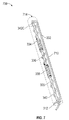
- FIG. 7 depicts a schematic view of another exemplary elongated flexible tube and an array of electrode pairs associated with a plurality of wires disposed within the flexible tube.
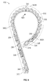
- FIG. 8 depicts a schematic view of another exemplary elongated flexible tube and an array of electrode pairs associated with a plurality of wires disposed within the flexible tube.
- FIG. 9A depicts a step of an exemplary method for treating a calcified heart valve using a shock wave device.
- FIG. 9B depicts another step of the exemplary method for treating a calcified heart valve using a shock wave device.
- FIG. 9C depicts another step of the exemplary method for treating a calcified heart valve using a shock wave device.
- FIG. 9D depicts another step of the exemplary method for treating a calcified heart valve using a shock wave device.
- FIG. 9E depicts another step of the exemplary method for treating a calcified heart valve using a shock wave device.
- FIG. 10 depicts a prospective view of one variation of a self-expanding anchor that may be used with a shock wave device.
- FIG. 11A schematically depicts another exemplary variation of a shock wave device for the treatment of calcified lesions in a heart valve.
- FIG. 11B schematically depicts another exemplary variation of a shock wave device for the treatment of calcified lesions in a heart valve.
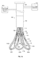
- FIG. 1A schematically depicts one variation of a shock wave device 100 for the treatment of calcified lesions in a heart valve.
- FIG. 1B schematically depicts exemplary elongated flexible tubes 110 A-C carried by a sheath 108 .
- the shock wave device 100 may comprise a first elongated flexible tube 110 A, a second elongated flexible tube 110 B, and a third elongated flexible tube 110 C.
- the elongated flexible tubes 110 A-C may be carried by a sheath 108 . At least part of the elongated flexible tubes 110 A-C may be movably accommodated within the sheath 108 .
- FIGS. 1A schematically depicts one variation of a shock wave device 100 for the treatment of calcified lesions in a heart valve.
- FIG. 1B schematically depicts exemplary elongated flexible tubes 110 A-C carried by a sheath 108 .
- the shock wave device 100 may comprise a first elongated flexible tube
- one or more of the elongated flexible tubes 110 A-C may be extended beyond the distal end of the sheath 108 for treating calcified lesions in heart valves.
- the sheath 108 may be coupled to a proximal handle 104 .
- the sheath 108 may be introduced into the vasculature and advanced in a retrograde direction (e.g., via a femoral artery) to a heart valve.
- the sheath 108 and the proximal handle 104 are similar to those described in more detail in co-pending U.S. patent application Ser. No. 13/962,315 filed Aug. 8, 2013 (U.S. Pat. Pub. No.
- shock wave device 100 may comprise any other numbers of elongated flexible tubes (e.g., one or two tubes).
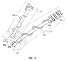
- FIG. 1C depicts a partial, enlarged view of an exemplary flexible tube.
- an elongated flexible tube 110 e.g., 110 A-C
- the fluid input end 152 and the fluid output end 154 may be located near a proximal end of the sheath 108 .
- a fluid may be introduced via the fluid input end 152 and discharged via the fluid output end 154 , or vice versa.
- the fluid may be introduced to the elongated flexible tube 110 by the fluid pump and fluid source 106 .
- the fluid pump and fluid source 106 may fill the elongated flexible tube 110 (e.g., 110 A-C) with a fluid such as saline or saline/contrast mixture.
- the fluid may be electrically conductive to support the generation of the shock waves.
- the elongated flexible tube 110 may have one fluid end, through which the fluid may be introduced to the tube and discharged from the tube.
- the fluid input end 152 and the fluid output end 154 may form one opening of the elongated flexible tube 110 .
- An elongated flexible tube 110 may comprise an inner wall and an outer wall.
- the inner wall of the elongated flexible tube 110 may be heat treated such that the surface of the inner wall is smoother than a surface that is not heat-treated.
- a smoother inner wall may reduce the absorption of the shock wave generated by an electrode pair and therefore enhance the efficiency of delivering the shock wave to treat the calcium deposits in a heart valve.
- a smoother surface may also reduce the resistance of circulating the fluid inside the elongated flexible tube 110 .
- a smoother surface may also reduce air bubble forming and trapping, which can diminish the shock wave sonic output.
- a hydrophilic coating may eliminate or reduce this problem.
- the elongated flexible tube 110 may have a ring-shaped cross-section.
- the inner wall of the elongated flexible tube 110 may form an inner cylinder to accommodate the wires, supporting wires, interleaved wire portions carrying electrode pairs, and the fluid.
- the inner diameter of the elongated flexible tube 110 may be ranging from about 0.04 inch to 0.08 inch; and the outer diameter of the elongated flexible tube 110 may be ranging from about 0.044 inch and about 0.088 inch; and the thickness of the wall of the elongated flexible tube 110 may be in the range of about 0.002 inch and about 0.02 inch.
- the thickness of the wall of the elongated flexible tube 110 may also increase the absorption of energy generated by an electrode pair, thereby reducing the acoustic pressure and shear stress (induced by the acoustic pressure pulse) that are applied to the calcified deposits along the surface of cusps of a heart valve.
- the elongated flexible tube 110 can have any desired cross-sectional shape and any desired dimensions for accommodate the components (e.g., wires, supporting wires, interleaved wire portions carrying electrode pairs, and the fluid) of a shock wave device for delivering the shock wave to treat the calcium deposits in a heart valve.
- the material of the elongated flexible tube 110 may include nylon, rubber, plastic, aromatic polyurethane, and/or other materials having similar characteristics.
- an elongated flexible tube 110 may comprise a loop portion.
- the loop portion may be located near a distal end of the sheath 108 .
- the loop portion may comprise a horseshoe-shaped loop such that the two ends of the loop portion are neighboring to each other.
- the loop portion may comprise a J-shaped loop (e.g., as shown in FIG. 6 ).
- the loop portion may be configured to be at least partially accommodated within a cusp of a heart valve to enable the shock waves to be delivered for softening and/or loosening and/or removing calcium deposits.
- the tube design is that the electrode pairs can be positioned in closer proximity to a cusp of a heart valve than of some prior art balloon designs wherein the electrodes are mounted close to the center sheath and away from the balloon wall.
- the flexible tube comprising a loop portion may enhance the delivering of the shock wave to the calcium deposits.
- the loop portion of an elongated flexible tube 110 may comprise a plurality of wires and an array of interleaved wire portions carrying electrode pairs.
- the elongated flexible tube 110 A comprises a first wire 114 , a first interleaved wire portion 116 , a second wire 118 , a second interleaved wire portion 120 , a third wire 122 , a third interleaved wire portion 124 , and a fourth wire 126 .
- An interleaved wire portion may comprise a plurality (e.g., 2) of portions of wires configured in an interleaved manner.
- an interleaved wire portion may include a portion of a wire coiled with a portion of another wire.
- the wires and interleaved wire portions are configured in series.
- the first wire 114 may be electrically coupled to a positive terminal of a voltage source such as a high voltage pulse generator 102 .
- the first interleaved wire portion 116 may comprise a portion of the first wire 114 interleaved with a first portion of the second wire 118 .
- the first wire 114 may have an electrical voltage or potential that is more positive than the second wire 118 .
- the second interleaved wire portion 120 may comprise a second portion of the second wire 118 interleaved with a first portion of the third wire 122 .
- the second wire 118 may have an electrical voltage or potential that is more positive than that of the third wire 122 .
- the third interleaved wire portion 124 may comprise a second portion of the third wire 122 and a portion of the fourth wire 126 .
- the third wire 122 may have an electrical voltage or potential that is more positive than that of the fourth wire 126 .
- the fourth wire 126 may be electrically coupled to a negative terminal of a voltage source such as a high voltage pulse generator 102 . While FIGS.
- an elongated flexible tube 110 may comprise any number of interleaved wire portions (e.g., two, three, four, five, six) in any desired configurations to deliver shock waves.
- the elongated flexible tube 110 A may comprises two interleaved wire portions (e.g., the first interleaved wire portion 116 and the second interleaved wire portion 120 ) coupled in series, but may not comprise the third interleaved wire portion 124 and the fourth wire 126 .
- the third wire 122 may be electrically coupled to the negative terminal of a voltage source such as a high voltage pulse generator 102 .
- one or more interleaved wire portions may also be electrically coupled in parallel.
- each interleaved wire portion includes at least one pair of electrodes.
- Each electrode is defined by removing a small region of insulation from the wire.
- an electrohydraulic discharge generates plasma that generates a shock wave at the arc-generating region.
- a conductive-fluid-filled tube may be pressurized at 2 ATM to 6 ATM.
- the high voltage pulse generator 102 can generate high voltage pulses in the range of about 1 kV-6 kV peak to peak. In one variation, the high voltage pulse generator 102 generates a voltage of about 5.0 kV and delivers the voltage to a plurality of interleaved wire portions (e.g., the first interleaved wire portion 116 , the second interleaved wire portion 120 , and the third interleaved wire portion 124 ) carrying an array of electrode pairs. The array of electrode pairs can be configured to generate shock waves in the conductive fluid in response to the voltage pulses generated by the voltage pulse generator 102 , as described in more detail below.
- a plurality of interleaved wire portions e.g., the first interleaved wire portion 116 , the second interleaved wire portion 120 , and the third interleaved wire portion 124 .
- the array of electrode pairs can be configured to generate shock waves in the conductive fluid in response to the voltage pulses generated by the voltage pulse generator
- the wires and interleaved wire portions may be supported by support wire 160 disposed within the elongated flexible tube 110 .
- the support wire 160 may be elongated and flexible.
- the support wire 160 is non-conductive or metal with high dielectric insulator.
- Material of the support wire 160 can be polyimide coated Nitinol wire or similar property material.
- the support wire 160 may be in contact with the wires (e.g., the first wire 114 , the second wire 118 , the third wire 122 , and the fourth wire 126 ) and the plurality of interleaved wire portions (e.g., the first, second, and third interleaved wire portions 116 , 120 , and 124 ).
- the wires e.g., 114 , 118 , 122 , and 126
- the interleaved wire portions e.g., 116 , 120 , and 124
- the support wire 160 extends substantially through the elongated flexible tube 110 .
- the support wire 160 may comprise one or more layers of materials.
- the outer layer 171 of the support wire 160 may comprise an electrical insulator material such as rubber, plastic, ceramics, and/or other materials having similar characteristics.
- the inner layer 172 of the support wire 160 may comprise an electrical conductor such as metal, alloy, nitinol, stainless steel, iron, copper, aluminum, lead, and/or other materials having similar characteristics.
- the inner layer 172 may comprise memory materials such as memory alloys to remember the shape of the support wire 160 to reduce the burden of the practitioner to adjust the shape of the elongated flexible tube 110 each time it is inserted into the heart valve of the same patient.
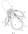
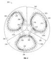
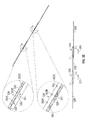
- FIG. 2 depicts a schematic top view of a shock wave device deployed in a heart valve 200 .
- the shock wave device may comprise a plurality of elongated flexible tubes.
- the shock wave device comprises a first elongated flexible tube 210 A, a second elongated flexible tube 210 B, and a third elongated flexible tube 210 C.
- the elongated flexible tubes 210 A-C may each comprise two or more interleaved wire portions carrying electrode pairs.
- the elongated flexible tube 210 A comprises interleaved wire portions 212 , 214 , and 216 ;
- the elongated flexible tube 210 B comprises interleaved wire portions 222 , 224 , and 226 ;
- the elongated flexible tube 210 C comprises interleaved wire portions 232 , 234 , and 236 .
- Each of the interleaved wire portions may carry a plurality of electrode pairs to generate shock waves.
- the elongated flexible tubes 210 A-C may further comprise markers 252 , 254 , and 256 , respectively.
- a marker may be disposed in the loop portion of the elongated flexible tube 210 .
- the marker 252 is co-axially coupled to a support wire 253 supporting the interleaved wire portions 212 , 214 , and 216 .
- Markers 254 and 256 may be similarly disposed.
- markers 252 , 254 , and 256 may be radiopaque to allow a practitioner to identify the location, position, and/or orientation of the shock wave device as it is inserted through the vasculature of a patient.
- the markers 252 , 254 , and 256 may be disposed proximal to the middle parts of the loop portions of elongated flexible tubes 210 A-C, respectively.
- one or more markers 252 , 254 , and 256 may be disposed proximal to one of the interleaved wire portions of elongated flexible tubes 210 A-C, or disposed at any other location along the length of the elongated flexible tubes 210 A-C.
- the markers 252 , 254 , and 256 may enable the practitioner to deploy the elongated flexible tubes 210 A-C to a proper location.
- the elongated flexible tubes 210 A-C may be deployed to a location within concaved portion and/or sinus 242 , 244 , and 246 of the respective cusp of the heart valve 200 .
- the location of the elongated flexible tubes 210 A-C may be determined based on fluoroscopy and/or ultrasound using the markers 252 , 254 , and 256 . As a result, a space may be maintained between the tubes and the wall of the heart valve 200 to prevent obstruction of the openings to the coronary arteries.
- the interleaved wire portions may be electrically coupled in series to a voltage source such as a high voltage pulse generator 102 .
- a voltage source such as a high voltage pulse generator 102 .
- one or more of the electrode pairs carried by the interleaved wire portions may be activated to produce shock waves.
- the location of the elongated flexible tubes 210 A-C and their electrode pairs may be monitored throughout the treatment procedure as needed to confirm that the electrode pairs are in close proximity to and/or in contact with calcified regions of the wall of the heart valve 200 .
- the electrode pairs may generate shock waves, which apply acoustic pulses of energy that propagate through the conductive fluid filled in the elongated flexible tubes 210 A-C.
- the acoustic pulses of energy generated from the electrode pairs e.g., electrode pairs carried the by interleaved wire portions 214 , 216 , 222 , 226 , 232 , and 236
- the thickness of the wall of an elongated flexible tube e.g., 210 A-C
- increasing the thickness of the wall of the elongated flexible tube 110 may increase the absorption of energy generated by an electrode pair, thereby reducing the acoustic pressure (and the induced stress associated with it) that is available to be applied to the calcified deposits along the surface of cusps of a heart valve.
- the thickness of the wall of the elongated flexible tube 110 may range from, for example, about 0.002 inch to 0.02 inch.
- the surface of the elongated flexible tubes 210 A-C may be heat treated such that it may be smoother than a surface that is not heat-treated.
- a smooth surface of elongated flexible tubes 210 A-C reduces or eliminates cavities or roughness to allow the pulses of energy to propagate in all directions.
- the thickness of the wall of an elongated flexible tube may be reduced when the surface of the wall is heat treated.
- a thinner wall may reduce the absorption of energy generated by an electrode pair.
- a thinner wall may also reduce the reflection of energy generated by an electrode pair.
- a thinner wall of an elongated flexible tube e.g., 210 A-C
- a heat treated surface may also reduce the absorption of the pulses of energy and thus reduce the stress applied on the elongated flexible tubes 210 A-C, thereby enhancing the life time of the tubes.
- a plurality of shock waves may be applied to the cusps and/or other valve structures of the heart valve 200 .
- the location and/or orientation of the elongated flexible tubes 210 A-C may be varied so that the energy from the shock waves may be positioned on different areas of a cusp.
- shock wave treatment of a calcified cusp may comprise initiating shock waves from the electrode pairs carried by the interleaved wire portions 214 and 216 of elongated flexible tube 210 A at a first location (which may, for example, apply mechanical forces to calcified deposits along a first edge of the cusp), then moving the elongated flexible tube 210 A and/or the interleaved wire portions 214 and 216 to a second location, and then initiating shock waves from the electrode pairs carried by the interleaved wire portions 214 and 216 at the second location (which may, for example, apply the mechanical forces to calcified deposits along the second edge of the cusp).
- the elongated flexible tubes 210 A-C may accommodate multiple interleaved wire portions carrying electrode pairs (e.g., 3) that can be positioned to treat calcified deposits along multiple edges of the cusp in series or in parallel configurations, therefore reducing or eliminating the requirement of moving the elongated flexible tubes 210 A-C and/or their respective electrode pairs.
- the shock waves can be generated from electrode pairs carried by interleaved wire portions 212 , 214 , and 216 electrically coupled in series to apply mechanical forces to calcified deposits along multiple (e.g., three) edges of the cusp.
- the location and or/orientation of the electrode pairs inside the elongated flexible tubes 210 A-C may be varied so that the acoustic energy of the emitted shock waves may coherently interfere at a particular location causing a higher energy wave than the original emitted pulse. This can be achieved by geometrically aligning the electrode pairs and firing them at the same time so that the waves can create a focal region at a particular location near or at the calcified valve. Efficacy of the treatment may be subsequently evaluated based on imaging techniques (e.g., fluoroscopy and/or ultrasound) and/or physiological parameters.
- imaging techniques e.g., fluoroscopy and/or ultrasound
- Examples of techniques that may be used to evaluate the efficacy of the treatment may include, but are not limited to, visual observation by ultrasound of leaflet activity (e.g., leaflet opening and closing) when the elongated flexible tubes 210 A-C are withdrawn from the heart valve 200 , measuring ejection fraction, Duke Activity Status Index (DASI), peak velocity, peak gradient, aortic valve area (AVA), Doppler velocity, etc.
- DASI Duke Activity Status Index
- peak velocity peak gradient
- AAVA aortic valve area
- Doppler velocity etc.
- TAVI transcatheter aortic valve implantation
- a single cusp of the heart valve 200 may be treated at a time, while in other variations, two or more cusps of a valve may be treated in parallel. For example, as illustrated in FIG. 2 , three cusps of the heart valve 200 may be treated in parallel with the three elongated flexible tubes 210 A-C. Alternatively, three cusps of the heart valve 200 may be treated one after another using a single elongated flexible tube of a shock wave device. For people with bicuspid aortic valves, a shock wave device having two elongated flexible tubes may be used to treat the two cusps of the heart valve.
- FIG. 3A depicts a schematic view of an exemplary flexible tube 300 and an array of electrode pairs associated with a plurality of wires disposed within the flexible tube 300 .
- an elongated flexible tube 310 may comprise a fluid input end 312 , a fluid output end 314 , a support wire 320 , a first wire 340 , a first interleaved wire portion 338 , a second wire 336 , a second interleaved wire portion 334 , a third wire 332 , a third interleaved wire portion 330 , and a fourth wire 328 .
- the wires 340 , 336 , and 332 may comprise a first layer surrounded by a second layer.
- the first layer may comprise conductive materials such as metal (e.g., copper), alloy, and/or other materials that are electrically conductive.
- the second layer may comprise insulator materials such as rubber, plastics, and/or other materials that are not electrically conductive.
- the first interleaved wire portion 338 may comprise a portion of the first wire 340 interleaved with a first portion of the second wire 336 .
- the first wire 340 may be electrically coupled to a positive terminal of a voltage source and may have an electrical voltage or potential that is more positive than the second wire 336 .
- the second interleaved wire portion 334 may comprise a second portion of the second wire 336 interleaved with a first portion of the third wire 332 .
- the second wire 336 may have an electrical voltage or potential that is more positive than that of the third wire 332 .
- the third interleaved wire portion 330 may comprise a second portion of the third wire 332 and a portion of the fourth wire 328 .
- the third wire 332 may have an electrical voltage or potential that is more positive than that of the fourth wire 328 .
- the fourth wire 328 may be electrically coupled to a negative terminal of a voltage source such as a high voltage pulse generator 102 .
- the electrical voltage or potential decreases in the order of the first wire 340 , the second wire 336 , the third wire 332 , and the fourth wire 328
- the electrical voltage or potential of these wires may increase in the other variations (e.g., the fourth wire 328 has a higher voltage or potential than the third wire 332 , which has a higher voltage or potential than the second wire 336 , and so forth).
- the portion of the first wire 340 interleaves with the first portion of the second wire 336 to form a first coil.
- the first coil may have a center axis that is common to the portion of the first wire 340 and the first portion of the second wire 336 .
- the second portion of the second wire 336 interleaves with the first portion of the third wire 332 to form a second coil.
- the second coil may have a center axis that is common to the second portion of the second wire 336 and the first portion of the third wire 332 .
- the second portion of the third wire 332 interleaves with a portion of the fourth wire 328 to form a third coil.
- the third coil may have a center axis that is common to the second portion of the third wire 332 and the portion of the fourth wire 328 .
- the coils may comprise two portions of two different wires interleaved to each other in a manner that two neighboring wire portions in the coils are substantially parallel to each other.
- the two neighboring wire portions may have different electrical voltage or potential.
- two neighboring wire portions may carry an electrode pair, which comprise one or more arc-generating regions to generate shock waves.
- the energy associated with the shock waves may vary depending on the distance between the arc-generating regions of the two neighboring wire portions.
- the shock wave generated may carry an increased energy with a reducing distance between the arc-generating regions the two neighboring wire portions.
- the distance may be reduced to a certain threshold, as discussed in more detail below.
- the location and or/orientation of the arc-generating regions may be varied so that the acoustic energy of the emitted shock waves may coherently interfere at a particular location causing a higher energy wave than the original emitted pulse. This can be achieved by geometrically aligning the arc-generating regions and firing them at the same time so that the waves can create a focal region at a particular location near or at the calcified valve.
- the shock wave device may comprise a plurality of spacers 342 A-C.
- the spacers 342 A-C may be configured to space the array of electrode pairs 330 , 334 , and 338 away from the inner wall of the elongated flexible tube 310 .
- the electrode pairs carried by interleaved wire portions 330 , 334 , and 338 may generate shock waves.
- the shock waves may apply mechanical forces on the inner wall of the elongated flexible tube 310 . Some of the energy may be absorbed by the inner wall, which causes mechanical forces or stresses to be applied to the inner wall.
- the mechanical forces or stresses may increase as the distance between the electrode pairs carried by interleaved wire portions 330 , 334 , and 338 and the inner wall of the elongate flexible tube 310 reduces.
- the spacers 342 A-C can keep the interleaved wire portions 330 , 334 , and 338 away from being in contact with the inner wall of the elongated flexible tube 310 to reduce or minimize the forces or stresses applied to the inner wall.
- the spacers 342 A-C may enhance the life time of the elongated flexible tube 310 .
- the spacers 342 A-C may include ring-shaped spacers and/or any other shaped spacers (e.g., oval-shaped).
- FIG. 3B depicts multiple views of an exemplary flexible tube and enlarged view of exemplary interleaved wire portions carrying electrode pairs.
- FIG. 3B illustrates a front view 310 A, side views 310 B-C, and a top view 310 D of the elongated flexible tube 310 .
- FIG. 3B further depict enlarged views of exemplary interleaved wire portions 330 , 334 , and 338 .
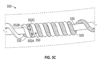
- FIG. 3C depicts an enlarged view of the interleaved wire portion 330 supported by a flexible support wire 320 .
- an interleaved wire portion may comprise two wire portions interleaved together to form a coil.
- the coil may comprise two portions of different wires interleaved to each other in a manner that two neighboring wire portions are substantially parallel to each other.
- two neighboring wire portions may have different electrical voltages or potentials.
- each of the two neighboring wire portions may comprise one or more arc-generating regions to form an electrode pair. For example, as shown in FIGS.
- the two neighboring portions of wires 328 and 332 in the interleaved wire portion 330 comprise one or more arc-generating regions 352 A-C and 350 , respectively.
- the wire portions of interleaved wire portions 334 and 334 may also comprise one or more arc-generating regions.
- the neighboring arc-generating regions may form electrode pairs.
- the arc-generating regions 350 and 352 A-C form an electrode pair.
- the arc-generating regions may be devoid of insulation and may be configured to generate sparks (or plasma arcs) between two neighboring wire portions to convey the shock waves.
- a wire e.g., wire 328 , 332 , 336 , and 340
- a wire may comprise a first layer that is electrically conductive and a second layer that is an electrical insulator.
- the first layer of a wire may be surrounded by the second layer.
- the insulation of the wires is removed to expose the underlying electrically conductive layer.
- two neighboring wire portions in a coil may be configured to be substantially parallel to each other.
- the arc-generating regions of two neighboring wire portions may be positioned to align with one another.
- the arc-generating region 350 of the portion of wire 332 may be positioned to align with the arc-generating region 352 A of the portion of wire 328 .
- the alignment of arc-generating regions between two neighboring wire portions may improve the efficiency of spark generation (or plasma arc generation). For example, plasma arcs may be more easily generated between two closely positioned arc-generating regions.
- the distance between the two arc-generating regions may be reduced to a certain threshold associated with an optimum acoustic energy output.
- the distance between the two arc-generating regions may be reduced to about 0.2 mm (or about 0.008 inch). Further reducing the distance may reduce the acoustic energy output.
- the distance may be divided serially in several electrode gaps.
- a wire portion that has a more positive electrical voltage or potential than the neighboring wire portion may comprise a smaller number of arc-generating regions.
- the portion of the wire 328 comprises at least two arc-generating regions 352 A-C and the portion of the wire 332 comprises one arc-generating regions.
- the portion of the wire 332 may have an electrical voltage or potential that is more positive than the portion of wire 328 , and thus the portion of wire 332 may have a smaller number of arc-generating regions the portion of wire 328 .
- the number of the arc-generating regions and/or the positions of the arc-generating regions may be configured to compensate spark-induced (or arc-induced) erosion of the insulation of one or both of the neighboring wire portions.
- the portion of the wire 332 comprises at least two arc-generating regions and the portion of the wire 336 comprises one arc-generating regions.
- the portion of the wire 336 may have an electrical voltage or potential that is more positive than the portion of the wire 332 , and thus wire 336 may have a smaller number of arc-generating regions than the portion of wire 332 .
- the portion of the wire 336 comprises at least two arc-generating regions and the portion of the wire 340 comprises one arc-generating regions.
- the portion of the wire 340 may have an electrical voltage or potential that is more positive than the portion of the wire 336 , and thus the portion of the wire 340 may have a smaller number of arc-generating regions than the portion of wire 336 .
- FIG. 3D depicts a schematic view of two neighboring interleaved wire portions in a coiled configuration and their enlarged view.
- FIG. 3E depicts a schematic view of two neighboring interleaved wire portions with the coils straightened and their enlarged view.
- FIGS. 3D and 3E are described together.
- FIGS. 3D and 3E illustrate the interleaved wire portions 330 and 334 .
- the interleaved wire portion 330 may comprise a portion of the wire 328 interleaved (e.g., coiled) with a portion of wire 332 .
- the wire 328 may have a voltage or potential that is more negative than the wire 332 .
- the wire 328 may be electrically coupled to a negative terminal of a voltage source.
- the portion of the wire 328 and the portion of the wire 332 may comprise one or more arc-generating regions configured to form an electrode pair.
- the portion of the wire 328 may include a plurality of arc-generating regions 352 A-C and the portion of the wire 332 may include one arc-generating region 350 .
- Arc-generating regions 350 and 352 A-C form an electrode pair.
- the arc-generating regions may be devoid of insulation for inducing electrical sparks (or plasma arcs) between the two arc-generating regions that have different voltages or potentials.
- plasma arcs may be generated between two neighboring arc-generating regions 350 and 352 A, because the wire 328 has a voltage or potential that is more negative than the wire 332 .
- plasma arcs may cause erosion of the insulation of the wires. Erosion may occur in the direction corresponding to the direction of increasing voltage or potential. For example, as shown in FIGS. 3D and 3E , in the portion of the wire 332 of interleaved wire portion 330 , the voltage or potential may increase in the direction indicated by an arrow 351 . Thus, the insulation erosion of the portion of the wire 332 may initiate from the arc-generating region 350 and propagate in the direction indicated by the arrow 351 .
- the arc-generating region in two neighboring wire portions may be positioned to compensate the arc-induced erosion of the insulation of one or more of the wire portions. For example, as shown in FIGS.
- the arc-generating region 350 and the arc-generating region 352 A may be positioned to align with each other to initiate the spark generation (or plasma arc generation).
- one or more additional arc-generating regions 352 B-C in the portion of wire 328 may be positioned corresponding to the erosion direction in the portion of the wire 332 , such that as the insulation erosion of the portion of the wire 332 propagate in the direction indicated by the arrow 351 , plasma arcs may be generated between the one or more addition arc-generating regions 352 B-C and the eroded portion of the wire 332 .
- one or more additional arc-generating regions may be positioned corresponding to the erosion direction in the portion of the wire 332 . Positioning the arc-generating regions in such a manner may increase the efficiency of spark/plasma arc generation, improve the consistency and continuity of the shock waves, and enhance the lifetime of the shock wave device.
- plasma arcs may cause erosion of the insulation of the wires. Erosion may occur in the direction corresponding to the direction of increasing voltage or potential.
- a shock wave device with polarity switching may be used with a regular electrode configuration (similar to those described in co-pending U.S. patent application Ser. No. 15/138,147, filed Apr. 25, 2016, which is incorporated by reference in its entirety) to even the directional erosion mentioned above.
- the insulation erosion of the portion of the wire 332 as shown in FIGS.
- 3D and 3E may initiate from the arc-generating region 350 and propagate in the direction indicated by the arrow 351 , and in the next pulse or subsequent number of pulses, may propagate in the direction opposite to that one in the arrow 351 , allowing erosion to act evenly on both sides and preventing the electrode gap from continuing to wear in an even fashion (as described in more detail in U.S. patent application Ser. No. 15/138,147, filed Apr. 25, 2016).
- the voltage or potential increases in the direction indicated by an arrow 361 .
- the insulation erosion of the portion of the wire 336 may initiate from the arc-generating region 360 and propagate in the direction indicated by the arrow 361 .
- the arc-generating regions in two neighboring wire portions may be positioned to compensate the arc-induced erosion of the insulation of one or more of the wire portions.
- the arc-generating region 360 and the arc-generating region 362 A may be positioned to align with each other to initiate the spark generation.
- one or more additional arc-generating regions 362 B-C in the portion of the wire 332 may be positioned corresponding to the erosion direction in the portion of the wire 336 , such that plasma arcs may be generated between the one or more addition arc-generating regions 362 B-C and the eroded portion of the wire 336 .
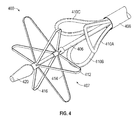
- the shock wave device may comprise a self-expanding anchor, which may be expanded automatically after the anchor is deployed.
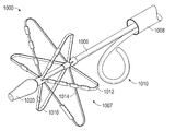
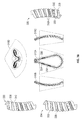
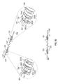
- FIG. 4 depicts a prospective view of one variation of a self-expanding anchor that may be used with a shock wave device.
- a shock wave device 400 may comprise a sheath 408 , a plurality of elongated flexible tubes 410 A-C, a shaft 406 , and an anchor 407 .
- the sheath 408 and plurality of elongated flexible tube 410 A-C are similar to those described above.
- the anchor 407 may comprise a self-expanding scaffold 414 .
- the device 400 may comprise an atraumatic tip 420 located at the distal end of the shaft 406 .
- the scaffold 414 may comprise one or more closed-form structures, such as lobes (or arms) 416 .
- the arms 416 may be arranged in a radial symmetric configuration around the shaft 406 , or in other variations, may be arranged in a non-symmetric configuration.
- the anchor 407 may comprise shape-memory material such as nickel-titanium alloy.
- the anchor 407 may be a central anchor extending between and beyond the ends of the elongated flexible tubes 410 A-C and configured to pass through the leaflets of the heart valves and into the ventricle to stabilize the position of the sheath 408 .
- the anchor 407 may be pushed through the valve orifice, expanded, and then pulled up against the heart valve leaflets to help further engage or contact the shock wave electrode pairs with the leaflets and/or cusps.
- the anchor 407 is similar to the anchor described in more detail in co-pending U.S. patent application Ser. No. 14/940,029 filed Nov. 12, 2015 (U.S. Pat. App. Publication 2016/0135828), which is hereby incorporated by reference in its entirety.
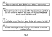
- FIG. 5 is a flowchart representation of a method for delivering shock waves to treat calcified lesions in a heart valve.
- a shock wave device may be introduced ( 502 ) into a patient's vasculature.
- the shock wave device may comprise one or more elongated flexible tubes (e.g., 3 ).
- the elongated flexible tube may be carried by a sheath and may have a fluid input end.
- the fluid input end of the tube may be located near a proximal end of the sheath.
- the tube may include a loop portion located near a distal end of the sheath.
- the loop portion may be configured to be at least partially accommodated within a cusp of the heart valve.
- the tube may be fillable with a conductive fluid via the fluid input end of the tube.
- the shock wave device may further comprise an array of electrode pairs associated with a plurality of wires positioned within the loop portion. The electrode pairs may be electrically connectable to a voltage source and configured to generate shock waves in the conductive fluid in response to voltage pulses.
- the shock wave device may be advanced ( 504 ) within the vasculature such that the loop portion of the tube is at least partially accommodated with a cusp of the heart valve.
- the tube of the shock wave device may be provided ( 506 ) with conductive fluid.
- the conductive fluid may be provided from a fluid source using a fluid pump.
- the voltage source may be activated ( 508 ) to apply shock waves to treat the calcified lesions of the heart valve.
- one or more cusps of a heart valve may be treated in serial or in parallel.
- FIG. 6 depicts a schematic view of another exemplary flexible tube 600 and an array of electrode pairs associated with a plurality of wires disposed within the flexible tube 600 .
- flexible tube 600 may comprise an elongated flexible tube 610 that includes a J-shaped curved portion 620 instead of a horseshoe-shaped loop portion of elongated flexible tube 310 .
- the J-shaped curved portion 620 may be configured to be at least partially accommodated within a cusp of the heart valve.
- the elongated flexible tube 600 may comprise a fluid input end 312 , a support wire 320 , a first wire 340 , a first interleaved wire portion 338 , a second wire 336 , a second interleaved wire portion 334 , a third wire 332 , a third interleaved wire portion 330 , and a fourth wire 328 .
- an array of three electrode pairs is disposed within the tube 610 .
- the first electrode pair is associated with a portion of the first wire 340 and a portion of the second wire 336 interleaved in a coiled configuration, with the first wire having an electrical potential that is more positive than that of the second wire.
- the second electrode pair is associated with a portion of the second wire 336 and a portion of the third wire 332 interleaved in a coiled configuration, with the second wire having an electrical potential that is more positive than that of the third wire.
- the third electrode pair is associated with a portion of the third wire 332 and a portion of the fourth wire 328 interleaved in a coiled configuration, with the third wire having an electrical potential that is more positive than that of the fourth wire.
- the distal end of the elongated flexible tube 600 (e.g., end 614 ) may be sealed such that the conducive fluid flows in and out through the open proximal end of the elongated flexible tube 610 (e.g., fluid input end 312 ).
- a wire associated with the electrode pair closest to the distal end of the tube is configured to extend at least from the sealed distal end of the tube to the open proximal end of the tube.
- a portion of the fourth wire 328 may be configured to return to the fluid input end 312 to electrically couple to a negative terminal of a voltage source such as a high voltage pulse generator 102 .
- the fourth wire which is associated with the electrode pair closest to the distal end of the tube, is configured to extend at least from the sealed distal end of the tube to the open proximal end of the tube.
- the portion of the fourth wire 328 that returns to the fluid input end 312 may be configured to be positioned away from the electrode pairs of the interleaved wire portions (e.g., wire portions 330 , 334 , and 338 ) such that it does not interfere with the shock wave generated by the electrode pairs.
- the portion of the fourth wire 328 that returns to the fluid input end 312 may be configured to be positioned in the opposite side from the side of the arc-generating regions of the interleaved wire portions 338 , 334 , and 330 .
- the elongated flexible tube 600 comprising a J-shaped curved portion may have a smaller dimension (e.g., length) than the elongated flexible tube 310 comprising a horseshoe-shaped loop portion. Smaller dimension may enable the shock wave device to be advanced more easily within the vasculature.
- a pressure relief valve may be attached to the fluid output end so the pump can deliver the conductive fluid at a constant pressure; additionally or alternatively, a pressure regulator may be attached at the fluid input end.
- the elongated flexible tube may include an output port at the proximal end of the tube such that the fluid makes a U-turn through the separated lumen.
- the support wire is a nitinol tube
- the nitinol tube can be used to flush the elongated flexible tube with fresh fluid, which enters the elongated flexible tube via the distal end of the nitinol tube. Suction may be applied at the output port at the proximal end of the elongated flexible tube to increase the outward flow of the fluid.
- FIG. 8 depicts a schematic view of the exemplary flexible tube 610 in an exemplary deployment configuration (i.e., after the tube is extended out of the sheath and before the tube is filled with a fluid).
- the flexible tube 610 includes a loop portion located near a distal end of the sheath.
- the shape of the loop portion may be set by the support wire.
- the loop portion of the elongated flexible tube 610 is configured to partially unfold when the tube is filled with a pressurized conductive fluid via the open proximal end of the tube.
- the tube 610 is inflated with the pressurized conductive fluid, which causes the loop portion to partially unfold and take on a U shape.
- the curve of the distal end of the tube (depicted in FIG. 8 ) is more closed than the curve of the distal end in the operating configuration (depicted in FIG. 6 ).
- FIGS. 9A-9D depict an exemplary method for treating a calcified heart valve (e.g., an aortic valve) using a shock wave device such as the one depicted in FIG. 8 .
- a shock wave device comprising two elongated flexible tubes
- this method may be performed using a shock wave device comprising one or three elongated flexible tube(s).
- FIG. 9A depicts a cross-sectional schematic view of an aortic valve with the left cusp 902 and the right cusp 904 (the posterior cusp is not shown for the sake of simplicity).
- the concave portion 903 of the left cusp 902 includes the opening 907 of the left coronary artery 906 .
- the concave portion 905 of the right cusp 904 includes the opening 909 of the right coronary artery 908 .
- a sheath 910 may be introduced into the vasculature and advanced in a retrograde direction (e.g., via a femoral artery) to the aortic valve.
- the sheath 910 (as well as any of components of the shock wave device) may comprise a radiopaque band or marker so that the location of the sheath may be determined using fluoroscopy. Alternatively or additionally, the location of the sheath and/or any shock wave devices may be determined using ultrasound.
- the distal end of the sheath 910 may be positioned close to but spaced from the cusps of the heart valve.
- a shock wave device 912 may then be advanced through the sheath 910 to the aortic valve.
- the shock wave device 912 may comprise a first elongated flexible tube 914 and a second elongated flexible tube 924 .
- both elongated flexible tubes 914 and 924 are straightened out within the sheath.
- the distal end of the first elongated flexible tube 914 and the distal end of the second elongated flexible tube 924 are both unfolded and maintain substantially straight against the wall of the sheath.
- the straight shape allows the elongated flexible tubes to be carried within a sheath having a smaller diameter.
- the distal ends of the tubes are biased (or prebent) such that they will curl into loops when extended out of the sheath.
- both distal ends of the tubes start to curl into their prebent/deployment shape (i.e., loops).
- the distal end of the elongated flexible tube 914 curls into a loop portion 916 and the distal end of the second elongated flexible tube 924 curls into a loop portion 926 .
- the loop portions are configured to partially unfold when the corresponding tubes are filled with a pressurized conductive fluid.
- the shaft portions above the loop portions of the elongated tubes may be biased such that they bend at an angle.
- the shock wave device 912 may be advanced through the sheath 910 in a compressed configuration, where the shaft portions of the first and second elongated flexible tubes are generally aligned with the longitudinal axis of the sheath 910 .
- extending the shock wave device 912 distally beyond the distal end of the sheath may allow the shaft portions 918 and 928 to assume their bent configuration, thereby expanding the shock wave device such that the first and second loop portions 916 , 926 (deflated during delivery) contact the aortic valve wall.
- the expansion of the shock wave device may at least partially align the loop portions with the concave portions 903 , 905 of the left and right cusps.
- the loop portions 916 and 926 of the tubes are at least partially accommodated within the cusps of the heart valve.
- one or both of the loop portions may be filled with a pressurized conductive fluid via the open proximal ends of the tubes.
- the fluid causes each of the loop portions 916 and 926 to partially unfold into curved portions 930 and 932 , respectively.
- the curved portions 930 and 932 self-align within the concave portions of the cusps.
- only one tube may be inflated at a time, or two tubes may be inflated simultaneously. Inflating fewer tubes than the number of cusps of a valve may allow blood to flow through at least a portion of the valve, which may help to reduce the risk of an ischemic incident during the procedure.
- one or more of the electrode pairs in the tubes may be activated to produce shock waves.
- the mechanical force from the shock waves may propagate through the conductive fluid to apply a mechanical force on any calcified deposit along the surface of the cusps.
- a single cusp of a valve may be treated at a time, while in other methods, two or more cusps of a valve may be treated simultaneously.
- FIG. 10 depicts a prospective view of one variation of a self-expanding anchor that may be used with a shock wave device.
- a shock wave device 1000 may comprise a single elongated flexible tube 1010 , a sheath 1008 , a shaft 1006 , and an anchor 1007 .
- the single elongated flexible tube 1010 is similar to the elongated flexible tube 610 in FIG. 6 and/or any of the tubes 914 and 924 in FIG. 9A .
- the components of the device 1000 are arranged to operate in a similar manner as described above with respect to the shock wave device 400 in FIG. 4 .
- the central anchor 1007 may extend beyond the sealed distal end of the tube 1010 and can be configured to pass through the leaflets of the heart valves and into the ventricle to stabilize the position of the sheath.
- the central anchor 1007 includes a plurality of arms 1012 , 1014 , 1016 , 1018 , 1022 , and 1024 .
- One or more markers may be disposed in a unique configuration on each of the plurality of arms such that the location of each arm can be identified during a procedure.
- the markers may include marker bands wrapped around the arms, markers glued on or crimped onto the arms, or a combination thereof.
- the configurations of marker(s) on two given arms may be different in marker count, marker shape, marker length, marker arrangement on the arm, or a combination thereof.
- a first configuration corresponding to arm 1012 includes a series of four markers arranged in a linear fashion
- the second configuration corresponding to arm 1014 includes a single marker that is longer than any of four markers on the first arm 1012 .
- the different marker configurations on the arms of the central anchor 1007 help a practitioner to identify the locations/positions/orientations of the arms and to navigate the elongated tube(s) of the shock wave device (e.g., the single elongated flexible tube 1010 ) from one cusp to another during a procedure.
- the shock wave device 1000 is introduced into a patient's vasculature and advanced within the vasculature such that the central anchor 1007 is placed into the ventricle.
- the anchor 1007 may be pushed through the valve orifice, expanded, and then pulled up against the heart valve leaflets to help further engage or contact the shock wave electrode pairs with the leaflets and/or cusps.
- the locations of the arms are determined.
- the locations of the arms may be determined based on fluoroscopy and/or ultrasound using the markers configurations. For example, upon identifying a configuration including a series of four markers of a certain length based on fluoroscopy, the practitioner can determine the location of the arm 1012 .
- the tube 1010 is deployed and positioned such that the distal end of the tube (e.g., the loop portion) is at least partially accommodated with a first cusp of the heart valve.
- the first cusp of the heart valve may be in proximity to a particular arm of the central anchor.
- the tube 1010 is positioned in proximity to the particular arm based on the determined location of the particular arm.
- the tube 1010 is filled with a pressurized conductive fluid such that the loop portion partially unfolds into a less curved portion, as discussed above with respect to FIGS. 9A-D .
- one or more of the electrode pairs in the tubes may be activated to produce shock waves to treat the calcified lesions.
- Efficacy of the treatment for the first cusp may be subsequently evaluated based on imaging techniques (e.g., fluoroscopy and/or ultrasound) and/or physiological parameters.
- the tube may be repositioned based on the determined locations of the arms of the central anchor such that the distal end of the tube is at least partially accommodated with a second cusp of the heart valve. Steps as described above are repeated such that the curved portion of the tube is located in the desired position, and the voltage source is activated to apply shock waves to treat the calcified lesions. It should be appreciated that the above-described method can be applied using any type of elongated flexible tube described herein.
- FIG. 7 depicts a schematic view of another exemplary flexible tube 700 and an array of electrode pairs associated with a plurality of wires disposed within the flexible tube 700 .
- flexible tube 700 may comprise an elongated flexible tube 710 that includes a straight portion, instead of a horseshoe-shaped loop portion or a J-shaped loop portion. The straight portion may be located near the distal end of a sheath.
- the elongated flexible tube 710 may comprise a fluid input end 312 , a support wire 320 , a first wire 340 , a first interleaved wire portion 338 , a second wire 336 , a second interleaved wire portion 334 , and a third wire 332 . These components are similar to those described above in connection with FIG. 3A and are thus not repeatedly described.
- the distal end of the elongated flexible tube 710 (e.g., end 714 ) may be sealed such that the conducive fluid flows in and out through the fluid input end 312 .
- a wire associated with the electrode pair closest to the distal end of the tube is configured to extend at least from the sealed distal end of the tube to the open proximal end of the tube.
- a portion of the third wire 332 may be configured to return to the fluid input end 312 to electrically couple to a negative terminal of a voltage source such as a high voltage pulse generator 102 .
- the portion of the third wire 332 that returns to the fluid input end 312 may be configured to be positioned away from the electrode pairs of the interleaved wire portions (e.g., wire portions 334 and 338 ) such that it does not interfere with the shock wave generated by the electrode pairs.
- the portion of the third wire 332 that returns to the fluid input end 312 may be configured to be positioned in the opposite side from the side of the arc-generating regions of the interleaved wire portion 338 and 334 .
- the elongated flexible tube 710 comprising a straight portion may be configured to be accommodated in a portion of a patient's body that has similar shape (e.g., the patient's knee).
- the elongated flexible tube 710 comprising a straight portion may have a smaller dimension (e.g., length) than the elongated flexible tube 310 comprising a horseshoe-shaped loop portion or the elongated flexible tube 610 comprising a J-shaped curved portion. Smaller dimension may enable the shock wave device to be advanced more easily within the vasculature.
- a single elongated tube e.g., tube 300 , tube 610 , tube 710 ) is carried within the sheath to so that a smaller sheath can be used. It is appreciated that a tube is not limited to the examples described herein and can have any desired shape.
- FIG. 11A schematically depicts another variation of a shock wave device 1100 for the treatment of calcified lesions in a heart valve.
- the shock wave device 1100 may comprise an elongated flexible tube 1110 .
- the elongated flexible tube 1110 may be carried by a sheath 1108 . At least part of the elongated flexible tubes 1110 may be movably accommodated within the sheath 1108 . As illustrated in FIG. 11A , the elongated flexible tube 1110 may be extended beyond the distal end of the sheath 1108 for treating calcified lesions in heart valves.
- the sheath 1108 may be coupled to a proximal handle 1104 . The sheath 1108 may be introduced into the vasculature and advanced in a retrograde direction (e.g., via a femoral artery) to a heart valve.
- the elongated flexible tube 1110 may comprise a fluid input end located near a proximal end of the sheath 1108 .
- a fluid may be introduced via the fluid input end.
- the fluid may be introduced to the elongated flexible tube 1110 by the fluid pump and fluid source 1106 .
- the fluid pump and fluid source 1106 may fill the elongated flexible tube 1100 with a fluid such as saline or saline/contrast mixture.
- the elongated flexible tube 1110 may have one fluid end, through which the fluid may be introduced to the tube and discharged from the tube.
- the elongated flexible tube 1100 has a loop portion 1130 , which is configured to be at least partially accommodated within a cusp of the heart valve.
- the shape of the loop portion may be set by the support wire 1160 A and the elongated flexible tube 1110 may be configured to operate in a manner consistent with the method described with reference to FIGS. 9A-E .
- the three shock wave generators 1126 A-C include three optical fibers of different lengths. Each of the optical fibers is connected to the laser generator 1102 . In some examples, each optical fiber is configured to generate shock waves at the distal end of the optical fiber in the fluid in response to laser pulses generated by the laser generator 1102 in a process called thermoelastic expansion. In some examples, an absorber substance is mixed into the fluid (e.g., saline), which is flushed into a part of the vasculature (e.g., artery), so that the laser is absorbed and shock waves are generated at the distal end of the optical fiber.
- a fluid e.g., saline
- the shock waves propagate from the distal end of the optical fiber through the vessel and to the tissue to be treated.
- the shock waves are generated at the interface of the target tissue due to pigment absorption.
- one mechanism for the lasers to act on tissue is via absorption and subsequent microablation. Because this type of lasers do not absorb well in certain fluids (e.g., saline), a part of the vasculature (e.g., artery) is flushed with the fluid (e.g., saline that is not mixed with any absorber substance) to clear out the blood.
- fluids e.g., saline that is not mixed with any absorber substance
- the laser in the form of a pulse wave
- the laser is propagated through the fluid until the laser encounters pigmented tissue that can absorb energy from the laser.
- pigmented tissue that can absorb energy from the laser.
- biological tissue that is calcified or diseased e.g., vessel endothelium or calcified tissue
- the shock waves are generated at the pigmented tissue rather than at the distal end of the optical fiber, in accordance with some embodiments.
- shock wave primary pressure wave
- a vapor bubble is also formed.
- the growth and subsequent collapse of the vapor cavity lead to secondary pressure waves (shock waves).
- shock wave generation in FIGS. 1A-C is a result of electrohydraulic vapor expansion, which has a different initial process of current discharge and ionization. Nevertheless, in both processes, the shock wave generation ends in a very similar acoustic pressure result and cavitation bubble activity.
- the elongated flexible tube include an optical fiber 1126 D, which is configured to be slidable along the elongated flexible tube. By sliding the optical fiber, the distal end thereof can be positioned at various locations within the tube permitting shock waves to be generated at the desired locations.
- the fiber may be initially positioned so that the distal end of the fiber is close to the distal end of the tube. During the procedure, the fiber can be withdrawn (in the direction of arrow A) allowing shock waves to be generated at increasingly more proximal locations within the tube. This slidable configuration may allow a smaller elongated flexible tube and/or sheath to be used.
Landscapes
- Health & Medical Sciences (AREA)
- Surgery (AREA)
- Life Sciences & Earth Sciences (AREA)
- Engineering & Computer Science (AREA)
- Public Health (AREA)
- Animal Behavior & Ethology (AREA)
- Nuclear Medicine, Radiotherapy & Molecular Imaging (AREA)
- Veterinary Medicine (AREA)
- General Health & Medical Sciences (AREA)
- Biomedical Technology (AREA)
- Heart & Thoracic Surgery (AREA)
- Medical Informatics (AREA)
- Molecular Biology (AREA)
- Physics & Mathematics (AREA)
- Mechanical Engineering (AREA)
- Orthopedic Medicine & Surgery (AREA)
- Vascular Medicine (AREA)
- Optics & Photonics (AREA)
- Otolaryngology (AREA)
- Electromagnetism (AREA)
- Surgical Instruments (AREA)
Abstract
Description
- This application claims priority to U.S. Provisional Patent Application No. 62/405,002, filed Oct. 6, 2016, which is incorporated herein by reference in its entirety.
- Aortic valve stenosis results in the narrowing of the aortic valve. Aortic valve stenosis may be exacerbated by a congenital defect where the aortic valve has one leaflet (unicuspid) or two leaflets (bicuspid) instead of three leaflets. In many cases, the narrowing of the aortic valve is the result of aortic valve calcification, where calcified plaque accumulates on the leaflets and/or annulus of the aortic valve. For example, calcium plaques deposited on the cusps of the leaflets may stiffen the leaflets, thereby narrowing the valve opening and interfering with efficient blood flow across the aortic valve.
- Although research is underway in the development of a replacement aortic valve, one may prefer to soften the leaflets by modifying (e.g., reducing) or cracking the calcium deposits on the native valve instead of replacing it with an artificial valve. Accordingly, improved methods of softening a calcified aortic valve may be desirable.
- Described herein are shock wave devices and methods for the treatment of calcified heart valves. The application of shock waves to a calcified region of a valve may help to crack and/or break the calcium deposits, thereby softening and/or loosening and/or removing calcium deposits that stiffen the mechanical properties of the valve. Softening and/or loosening and/or removing calcium deposits may allow the valve to regain at least a portion of its normal function. One embodiment of a shock wave device may comprise an elongated flexible tube carried by a sheath. The tube may have a fluid input end as well as fluid output end, which may be located near a proximal end of the sheath. The tube may include a loop portion located near a distal end of the sheath. The loop portion may be configured to be at least partially accommodated within a cusp of the heart valve. The tube may be fillable with a conductive fluid via the fluid input end of the tube. In some variations, the shock wave device may include an array of electrode pairs associated with a plurality of wires positioned within the loop portion of a tube. The electrode pairs may be electrically connectable to a voltage source and configured to generate shock waves in the conductive fluid in response to voltage pulses. Shock wave devices comprising at least two elongated flexible tubes and one or more electrode pairs may be used for treating unicuspid, bicuspid and/or tricuspid valves.
- Methods for delivering shock waves to treat calcified lesions of a heart valve may comprise introducing a shock wave device into a patient's vasculature. The shock wave device may comprise an elongated flexible tube carried by a sheath. The tube may have a fluid input end. The fluid input end of the tube may be located near a proximal end of the sheath. The tube may include a loop portion located near a distal end of the sheath. The loop portion of the tube may be configured to be at least partially accommodated within a cusp of the heart valve. The tube may be fillable with a conductive fluid via the fluid input end of the tube. The shock wave device may comprise an array of electrode pairs associated with a plurality of wires positioned within the loop portion. The electrode pairs may be electrically connectable to a voltage source and configured to generate shock waves in the conductive fluid in response to voltage pulses. Methods for delivering shock waves to treat calcified lesions of a heart valve may further comprise advancing the shock wave device within the vasculature such that the loop portion of the tube is at least partially accommodated with a cusp of the heart valve; providing the tube of the shock wave device with conductive fluid; and activating the voltage source to apply a shock waves to treat the calcified lesions.
- Other devices and methods that may be used to crack and/or break calcified deposits in an aortic valve (e.g., as part of a valvuloplasty procedure) are described in co-pending U.S. Pat. Pub. No. 2014/0046353 filed Aug. 8, 2013 (U.S. patent application Ser. No. 13/962,315); U.S. Pat. Pub. No. 2011/0295227 filed Aug. 10, 2011 (U.S. patent application Ser. No. 13/207,381, now U.S. Pat. No. 9,044,619), U.S. Pat. Pub. No. 2013/0116714 filed Nov. 8, 2011 (U.S. patent application Ser. No. 13/291,875, now U.S. Pat. No. 8,574,247), U.S. Pat. Pub. No. 2014/0163592 filed Aug. 1, 2013 (U.S. patent application Ser. No. 13/957,276, now U.S. Pat. No. 9,220,521 issued Dec. 29, 2015), which are hereby incorporated by reference in their entirety.
- One variation for delivering shock waves to treat calcified lesions in a heart valve (e.g., a heart valve having a plurality of cusps each having a concave portion) may comprise an elongated flexible tube carried by a sheath. The tube may have a fluid input end, which may be located near a proximal end of the sheath. The tube may include a loop portion located near a distal end of the sheath. The loop portion may be configured to be at least partially accommodated within a cusp of the heart valve. The tube may be fillable with a conductive fluid via the fluid input end of the tube and subsequently purge used conductive fluid through the fluid output tube located on the sheath. The device may further comprise an elongated flexible support wire disposed within the tube and at least two insulated wires supported by the elongated flexible support wire. At least two insulated wires may be coiled around the flexible support wire. The device may further comprise at least two electrode pairs included in at least two insulated wires positioned within the loop portion. Each of the electrode pairs may comprise a plurality of spark-generating regions (or arc-generating regions) formed within interleaved portions of two insulated wires of the at least two insulated wires. The arc-generating regions are devoid of insulation. At least two electrode pairs may be electrically connectable to a voltage source and configured to generate shock waves in the conductive fluid in response to voltage pulses.
- Any of the devices described herein may further comprise a plurality of spacers configured to space the array of electrode pairs away from the inner wall of the tube; a marker disposed in the loop portion of the tube; a fluid source, and a fluid pump. The fluid pump may be configured to deliver fluid from the fluid source to the fluid input end of the tube as well as remove fluid from the tube. To maintain the maximum shockwave output, it may be desirable to remove debris and air bubbles from the tube and replenish the tube with fresh conductive fluid. A pressure relief valve may be attached to the fluid output end so the pump can deliver the conductive fluid at a constant pressure. In some example, a pressure regulator may be attached at the fluid input end. Optionally, the device may further comprise at least one additional elongated flexible tube carried by the sheath, and a central anchor extending between and beyond the loop portions of the tubes and configured to pass through the leaflets of the heart valves and into the ventricle to stabilize the position of the sheath.
-
FIG. 1A schematically depicts one variation of a shock wave device for the treatment of calcified lesions in a heart valve. -
FIG. 1B schematically depicts exemplary elongated flexible tubes carried by a sheath. -
FIG. 1C depicts a partial, enlarged view of an exemplary elongated flexible tube of a shock wave device. -
FIG. 2 depicts a schematic top view of elongated flexible tubes deployed in a heart valve. -
FIG. 3A depicts a schematic view of an exemplary elongated flexible tube and an array of electrode pairs associated with a plurality of wires disposed within the flexible tube. -
FIG. 3B depicts various views of an exemplary flexible tube and enlarged view of exemplary interleaved wire portions carrying the electrode pairs. -
FIG. 3C depicts an enlarged view of an exemplary interleaved wire portion supported by a flexible support wire. -
FIG. 3D depicts a schematic view of two neighboring interleaved wire portions in a coiled configuration and their enlarged view. -
FIG. 3E depicts a schematic view of two neighboring interleaved wire portions with the coils straightened and their enlarged view. -
FIG. 4 depicts a prospective view of one variation of a self-expanding anchor that may be used with a shock wave device. -
FIG. 5 is a flowchart representation of a method for delivering shock waves to treat calcified lesions in a heart valve. -
FIG. 6 depicts a schematic view of another exemplary elongated flexible tube and an array of electrode pairs associated with a plurality of wires disposed within the flexible tube. -
FIG. 7 depicts a schematic view of another exemplary elongated flexible tube and an array of electrode pairs associated with a plurality of wires disposed within the flexible tube. -
FIG. 8 depicts a schematic view of another exemplary elongated flexible tube and an array of electrode pairs associated with a plurality of wires disposed within the flexible tube. -
FIG. 9A depicts a step of an exemplary method for treating a calcified heart valve using a shock wave device. -
FIG. 9B depicts another step of the exemplary method for treating a calcified heart valve using a shock wave device. -
FIG. 9C depicts another step of the exemplary method for treating a calcified heart valve using a shock wave device. -
FIG. 9D depicts another step of the exemplary method for treating a calcified heart valve using a shock wave device. -
FIG. 9E depicts another step of the exemplary method for treating a calcified heart valve using a shock wave device. -
FIG. 10 depicts a prospective view of one variation of a self-expanding anchor that may be used with a shock wave device. -
FIG. 11A schematically depicts another exemplary variation of a shock wave device for the treatment of calcified lesions in a heart valve. -
FIG. 11B schematically depicts another exemplary variation of a shock wave device for the treatment of calcified lesions in a heart valve. -
FIG. 1A schematically depicts one variation of ashock wave device 100 for the treatment of calcified lesions in a heart valve.FIG. 1B schematically depicts exemplary elongatedflexible tubes 110A-C carried by asheath 108. Theshock wave device 100 may comprise a first elongatedflexible tube 110A, a second elongatedflexible tube 110B, and a third elongatedflexible tube 110C. As illustrated inFIGS. 1A-1B , the elongatedflexible tubes 110A-C may be carried by asheath 108. At least part of the elongatedflexible tubes 110A-C may be movably accommodated within thesheath 108. As illustrated inFIGS. 1A-1B , one or more of the elongatedflexible tubes 110A-C may be extended beyond the distal end of thesheath 108 for treating calcified lesions in heart valves. In some variations, thesheath 108 may be coupled to aproximal handle 104. Thesheath 108 may be introduced into the vasculature and advanced in a retrograde direction (e.g., via a femoral artery) to a heart valve. Thesheath 108 and theproximal handle 104 are similar to those described in more detail in co-pending U.S. patent application Ser. No. 13/962,315 filed Aug. 8, 2013 (U.S. Pat. Pub. No. 2014/0046353), which is hereby incorporated by reference in its entirety. While three elongatedflexible tubes 110A-C are illustrated inFIGS. 1A-1B , it is appreciated that theshock wave device 100 may comprise any other numbers of elongated flexible tubes (e.g., one or two tubes). -
FIG. 1C depicts a partial, enlarged view of an exemplary flexible tube. As shown inFIG. 1C , in some variations, an elongated flexible tube 110 (e.g., 110A-C) may comprise afluid input end 152 and afluid output end 154. Thefluid input end 152 and thefluid output end 154 may be located near a proximal end of thesheath 108. A fluid may be introduced via thefluid input end 152 and discharged via thefluid output end 154, or vice versa. For example, the fluid may be introduced to the elongatedflexible tube 110 by the fluid pump andfluid source 106. The fluid pump andfluid source 106 may fill the elongated flexible tube 110 (e.g., 110A-C) with a fluid such as saline or saline/contrast mixture. The fluid may be electrically conductive to support the generation of the shock waves. In some variations, the elongatedflexible tube 110 may have one fluid end, through which the fluid may be introduced to the tube and discharged from the tube. For example, thefluid input end 152 and thefluid output end 154 may form one opening of the elongatedflexible tube 110. - An elongated flexible tube 110 (e.g.,
tubes 110A-C) may comprise an inner wall and an outer wall. In some variations, the inner wall of the elongatedflexible tube 110 may be heat treated such that the surface of the inner wall is smoother than a surface that is not heat-treated. A smoother inner wall may reduce the absorption of the shock wave generated by an electrode pair and therefore enhance the efficiency of delivering the shock wave to treat the calcium deposits in a heart valve. Moreover, a smoother surface may also reduce the resistance of circulating the fluid inside the elongatedflexible tube 110. A smoother surface may also reduce air bubble forming and trapping, which can diminish the shock wave sonic output. A hydrophilic coating may eliminate or reduce this problem. - In some variations, the elongated
flexible tube 110 may have a ring-shaped cross-section. For example, the inner wall of the elongatedflexible tube 110 may form an inner cylinder to accommodate the wires, supporting wires, interleaved wire portions carrying electrode pairs, and the fluid. As an example, the inner diameter of the elongatedflexible tube 110 may be ranging from about 0.04 inch to 0.08 inch; and the outer diameter of the elongatedflexible tube 110 may be ranging from about 0.044 inch and about 0.088 inch; and the thickness of the wall of the elongatedflexible tube 110 may be in the range of about 0.002 inch and about 0.02 inch. While increasing the wall thickness can improve strength, increasing the thickness of the wall of the elongatedflexible tube 110 may also increase the absorption of energy generated by an electrode pair, thereby reducing the acoustic pressure and shear stress (induced by the acoustic pressure pulse) that are applied to the calcified deposits along the surface of cusps of a heart valve. It is appreciated that the elongatedflexible tube 110 can have any desired cross-sectional shape and any desired dimensions for accommodate the components (e.g., wires, supporting wires, interleaved wire portions carrying electrode pairs, and the fluid) of a shock wave device for delivering the shock wave to treat the calcium deposits in a heart valve. In some variations, the material of the elongatedflexible tube 110 may include nylon, rubber, plastic, aromatic polyurethane, and/or other materials having similar characteristics. - As illustrated in
FIGS. 1A-1B , in some variations, an elongated flexible tube 110 (e.g., 110A-C) may comprise a loop portion. The loop portion may be located near a distal end of thesheath 108. In some variations, the loop portion may comprise a horseshoe-shaped loop such that the two ends of the loop portion are neighboring to each other. In some variations, the loop portion may comprise a J-shaped loop (e.g., as shown inFIG. 6 ). The loop portion may be configured to be at least partially accommodated within a cusp of a heart valve to enable the shock waves to be delivered for softening and/or loosening and/or removing calcium deposits. One advantage of the tube design is that the electrode pairs can be positioned in closer proximity to a cusp of a heart valve than of some prior art balloon designs wherein the electrodes are mounted close to the center sheath and away from the balloon wall. As a result, the flexible tube comprising a loop portion may enhance the delivering of the shock wave to the calcium deposits. The treatment of calcium deposits in a heart valve is described in more detail below in connection withFIG. 2 . - As shown in
FIGS. 1A-1C , the loop portion of an elongatedflexible tube 110 may comprise a plurality of wires and an array of interleaved wire portions carrying electrode pairs. For example, the elongatedflexible tube 110A comprises afirst wire 114, a first interleavedwire portion 116, asecond wire 118, a second interleavedwire portion 120, athird wire 122, a third interleavedwire portion 124, and afourth wire 126. An interleaved wire portion may comprise a plurality (e.g., 2) of portions of wires configured in an interleaved manner. For example, an interleaved wire portion may include a portion of a wire coiled with a portion of another wire. In some variations, the wires and interleaved wire portions are configured in series. For example, thefirst wire 114 may be electrically coupled to a positive terminal of a voltage source such as a highvoltage pulse generator 102. The first interleavedwire portion 116 may comprise a portion of thefirst wire 114 interleaved with a first portion of thesecond wire 118. Thefirst wire 114 may have an electrical voltage or potential that is more positive than thesecond wire 118. Similarly, the second interleavedwire portion 120 may comprise a second portion of thesecond wire 118 interleaved with a first portion of thethird wire 122. Thesecond wire 118 may have an electrical voltage or potential that is more positive than that of thethird wire 122. And the third interleavedwire portion 124 may comprise a second portion of thethird wire 122 and a portion of thefourth wire 126. Thethird wire 122 may have an electrical voltage or potential that is more positive than that of thefourth wire 126. Thefourth wire 126 may be electrically coupled to a negative terminal of a voltage source such as a highvoltage pulse generator 102. WhileFIGS. 1A-1B illustrate three interleavedwire portions flexible tube 110 may comprise any number of interleaved wire portions (e.g., two, three, four, five, six) in any desired configurations to deliver shock waves. For example, the elongatedflexible tube 110A may comprises two interleaved wire portions (e.g., the first interleavedwire portion 116 and the second interleaved wire portion 120) coupled in series, but may not comprise the third interleavedwire portion 124 and thefourth wire 126. In this configuration, thethird wire 122 may be electrically coupled to the negative terminal of a voltage source such as a highvoltage pulse generator 102. In some variations, one or more interleaved wire portions may also be electrically coupled in parallel. - As will be discussed below with reference to
FIGS. 3A-E , in the illustrated embodiment, each interleaved wire portion includes at least one pair of electrodes. Each electrode is defined by removing a small region of insulation from the wire. When a high voltage is delivered to the wires surrounded by a conductive fluid, an electrohydraulic discharge generates plasma that generates a shock wave at the arc-generating region. A conductive-fluid-filled tube may be pressurized at 2 ATM to 6 ATM. - In some variations, the high
voltage pulse generator 102 can generate high voltage pulses in the range of about 1 kV-6 kV peak to peak. In one variation, the highvoltage pulse generator 102 generates a voltage of about 5.0 kV and delivers the voltage to a plurality of interleaved wire portions (e.g., the first interleavedwire portion 116, the second interleavedwire portion 120, and the third interleaved wire portion 124) carrying an array of electrode pairs. The array of electrode pairs can be configured to generate shock waves in the conductive fluid in response to the voltage pulses generated by thevoltage pulse generator 102, as described in more detail below. - As shown in
FIGS. 1A-1C , in some variations, the wires and interleaved wire portions may be supported bysupport wire 160 disposed within the elongatedflexible tube 110. Thesupport wire 160 may be elongated and flexible. In some variations, thesupport wire 160 is non-conductive or metal with high dielectric insulator. Material of thesupport wire 160 can be polyimide coated Nitinol wire or similar property material. Thesupport wire 160 may be in contact with the wires (e.g., thefirst wire 114, thesecond wire 118, thethird wire 122, and the fourth wire 126) and the plurality of interleaved wire portions (e.g., the first, second, and third interleavedwire portions support wire 160. In some variations, thesupport wire 160 extends substantially through the elongatedflexible tube 110. One variation of thesupport wire 160 may comprise one or more layers of materials. For example, as shown inFIG. 1C , theouter layer 171 of thesupport wire 160 may comprise an electrical insulator material such as rubber, plastic, ceramics, and/or other materials having similar characteristics. Theinner layer 172 of thesupport wire 160 may comprise an electrical conductor such as metal, alloy, nitinol, stainless steel, iron, copper, aluminum, lead, and/or other materials having similar characteristics. In some variations, theinner layer 172 may comprise memory materials such as memory alloys to remember the shape of thesupport wire 160 to reduce the burden of the practitioner to adjust the shape of the elongatedflexible tube 110 each time it is inserted into the heart valve of the same patient. -
FIG. 2 depicts a schematic top view of a shock wave device deployed in aheart valve 200. As described, in some variations, the shock wave device may comprise a plurality of elongated flexible tubes. For example, as shown inFIG. 2 , the shock wave device comprises a first elongatedflexible tube 210A, a second elongatedflexible tube 210B, and a third elongatedflexible tube 210C. The elongatedflexible tubes 210A-C may each comprise two or more interleaved wire portions carrying electrode pairs. For example, as shown inFIG. 2 , the elongatedflexible tube 210A comprises interleavedwire portions flexible tube 210B comprises interleavedwire portions flexible tube 210C comprises interleavedwire portions - In some variations, the elongated
flexible tubes 210A-C may further comprisemarkers FIG. 2 , themarker 252 is co-axially coupled to asupport wire 253 supporting the interleavedwire portions Markers markers markers flexible tubes 210A-C, respectively. In some variations, one ormore markers flexible tubes 210A-C, or disposed at any other location along the length of the elongatedflexible tubes 210A-C. The markers flexible tubes 210A-C to a proper location. For example, using themarkers flexible tubes 210A-C may be deployed to a location within concaved portion and/orsinus heart valve 200. In some variations, the location of the elongatedflexible tubes 210A-C may be determined based on fluoroscopy and/or ultrasound using themarkers heart valve 200 to prevent obstruction of the openings to the coronary arteries. - As illustrated in
FIG. 2 , the interleaved wire portions (e.g., interleavedwire portions voltage pulse generator 102. After a practitioner confirms that the elongatedflexible tubes 210A-C are located in their pre-determined or desired positions, one or more of the electrode pairs carried by the interleaved wire portions may be activated to produce shock waves. The location of the elongatedflexible tubes 210A-C and their electrode pairs may be monitored throughout the treatment procedure as needed to confirm that the electrode pairs are in close proximity to and/or in contact with calcified regions of the wall of theheart valve 200. - As described in more detail below, the electrode pairs may generate shock waves, which apply acoustic pulses of energy that propagate through the conductive fluid filled in the elongated
flexible tubes 210A-C. The acoustic pulses of energy generated from the electrode pairs (e.g., electrode pairs carried the by interleavedwire portions flexible tube 110 may increase the absorption of energy generated by an electrode pair, thereby reducing the acoustic pressure (and the induced stress associated with it) that is available to be applied to the calcified deposits along the surface of cusps of a heart valve. The thickness of the wall of the elongatedflexible tube 110 may range from, for example, about 0.002 inch to 0.02 inch. In some variations, the surface of the elongatedflexible tubes 210A-C may be heat treated such that it may be smoother than a surface that is not heat-treated. A smooth surface of elongatedflexible tubes 210A-C reduces or eliminates cavities or roughness to allow the pulses of energy to propagate in all directions. Moreover, as a result of the smooth surface, some of the energy may be reflected and redirected to the calcified deposits, thereby enhancing the efficacy of the treatment. In some variations, the thickness of the wall of an elongated flexible tube (e.g., 210A-C) may be reduced when the surface of the wall is heat treated. A thinner wall may reduce the absorption of energy generated by an electrode pair. A thinner wall may also reduce the reflection of energy generated by an electrode pair. Thus, a thinner wall of an elongated flexible tube (e.g., 210A-C) may increase the pressure or stress that is available to be applied to the calcified deposits along the surface of cusps of a heart valve, thereby enhances the efficacy of the treatment. A heat treated surface may also reduce the absorption of the pulses of energy and thus reduce the stress applied on the elongatedflexible tubes 210A-C, thereby enhancing the life time of the tubes. - As shown in
FIG. 2 , a plurality of shock waves may be applied to the cusps and/or other valve structures of theheart valve 200. In some variations, the location and/or orientation of the elongatedflexible tubes 210A-C may be varied so that the energy from the shock waves may be positioned on different areas of a cusp. For example, shock wave treatment of a calcified cusp may comprise initiating shock waves from the electrode pairs carried by the interleavedwire portions flexible tube 210A at a first location (which may, for example, apply mechanical forces to calcified deposits along a first edge of the cusp), then moving the elongatedflexible tube 210A and/or the interleavedwire portions wire portions flexible tubes 210A-C may accommodate multiple interleaved wire portions carrying electrode pairs (e.g., 3) that can be positioned to treat calcified deposits along multiple edges of the cusp in series or in parallel configurations, therefore reducing or eliminating the requirement of moving the elongatedflexible tubes 210A-C and/or their respective electrode pairs. For example, as shown inFIG. 2 , the shock waves can be generated from electrode pairs carried by interleavedwire portions flexible tubes 210A-C are withdrawn from theheart valve 200, measuring ejection fraction, Duke Activity Status Index (DASI), peak velocity, peak gradient, aortic valve area (AVA), Doppler velocity, etc. Optionally, after a desired amount of the calcium deposits have been cracked and/or loosened, and/or the leaflets of the heart valve have been softened, a transcatheter aortic valve implantation (TAVI) procedure may be performed. Cracking and/or breaking the calcium deposits on a heart valve may help to improve the outcome of a subsequent TAVI procedure. In some variations, a single cusp of theheart valve 200 may be treated at a time, while in other variations, two or more cusps of a valve may be treated in parallel. For example, as illustrated inFIG. 2 , three cusps of theheart valve 200 may be treated in parallel with the three elongatedflexible tubes 210A-C. Alternatively, three cusps of theheart valve 200 may be treated one after another using a single elongated flexible tube of a shock wave device. For people with bicuspid aortic valves, a shock wave device having two elongated flexible tubes may be used to treat the two cusps of the heart valve. -
FIG. 3A depicts a schematic view of an exemplaryflexible tube 300 and an array of electrode pairs associated with a plurality of wires disposed within theflexible tube 300. As shown inFIG. 3A , an elongatedflexible tube 310 may comprise afluid input end 312, afluid output end 314, asupport wire 320, afirst wire 340, a first interleavedwire portion 338, asecond wire 336, a second interleavedwire portion 334, athird wire 332, a third interleavedwire portion 330, and afourth wire 328. One variation of thewires wire portion 338 may comprise a portion of thefirst wire 340 interleaved with a first portion of thesecond wire 336. Thefirst wire 340 may be electrically coupled to a positive terminal of a voltage source and may have an electrical voltage or potential that is more positive than thesecond wire 336. Similarly, the second interleavedwire portion 334 may comprise a second portion of thesecond wire 336 interleaved with a first portion of thethird wire 332. Thesecond wire 336 may have an electrical voltage or potential that is more positive than that of thethird wire 332. And the third interleavedwire portion 330 may comprise a second portion of thethird wire 332 and a portion of thefourth wire 328. Thethird wire 332 may have an electrical voltage or potential that is more positive than that of thefourth wire 328. Thefourth wire 328 may be electrically coupled to a negative terminal of a voltage source such as a highvoltage pulse generator 102. It is appreciated that while in the above variation, the electrical voltage or potential decreases in the order of thefirst wire 340, thesecond wire 336, thethird wire 332, and thefourth wire 328, the electrical voltage or potential of these wires may increase in the other variations (e.g., thefourth wire 328 has a higher voltage or potential than thethird wire 332, which has a higher voltage or potential than thesecond wire 336, and so forth). - As shown in
FIG. 3A , in some variations, the portion of thefirst wire 340 interleaves with the first portion of thesecond wire 336 to form a first coil. The first coil may have a center axis that is common to the portion of thefirst wire 340 and the first portion of thesecond wire 336. Similar, the second portion of thesecond wire 336 interleaves with the first portion of thethird wire 332 to form a second coil. The second coil may have a center axis that is common to the second portion of thesecond wire 336 and the first portion of thethird wire 332. And the second portion of thethird wire 332 interleaves with a portion of thefourth wire 328 to form a third coil. The third coil may have a center axis that is common to the second portion of thethird wire 332 and the portion of thefourth wire 328. - As shown in
FIG. 3A , in some variations, the coils may comprise two portions of two different wires interleaved to each other in a manner that two neighboring wire portions in the coils are substantially parallel to each other. The two neighboring wire portions may have different electrical voltage or potential. As described in more details below, in a coil, two neighboring wire portions may carry an electrode pair, which comprise one or more arc-generating regions to generate shock waves. The energy associated with the shock waves may vary depending on the distance between the arc-generating regions of the two neighboring wire portions. For example, the shock wave generated may carry an increased energy with a reducing distance between the arc-generating regions the two neighboring wire portions. In some variations, the distance may be reduced to a certain threshold, as discussed in more detail below. In some variations, the location and or/orientation of the arc-generating regions may be varied so that the acoustic energy of the emitted shock waves may coherently interfere at a particular location causing a higher energy wave than the original emitted pulse. This can be achieved by geometrically aligning the arc-generating regions and firing them at the same time so that the waves can create a focal region at a particular location near or at the calcified valve. - As illustrated in
FIG. 3A , in some variations, the shock wave device may comprise a plurality ofspacers 342A-C. The spacers 342A-C may be configured to space the array of electrode pairs 330, 334, and 338 away from the inner wall of the elongatedflexible tube 310. As described, the electrode pairs carried by interleavedwire portions flexible tube 310. Some of the energy may be absorbed by the inner wall, which causes mechanical forces or stresses to be applied to the inner wall. The mechanical forces or stresses may increase as the distance between the electrode pairs carried by interleavedwire portions flexible tube 310 reduces. Thespacers 342A-C can keep the interleavedwire portions flexible tube 310 to reduce or minimize the forces or stresses applied to the inner wall. As a result, thespacers 342A-C may enhance the life time of the elongatedflexible tube 310. In some variations, thespacers 342A-C may include ring-shaped spacers and/or any other shaped spacers (e.g., oval-shaped). -
FIG. 3B depicts multiple views of an exemplary flexible tube and enlarged view of exemplary interleaved wire portions carrying electrode pairs. For example,FIG. 3B illustrates afront view 310A, side views 310B-C, and atop view 310D of the elongatedflexible tube 310.FIG. 3B further depict enlarged views of exemplary interleavedwire portions FIG. 3C depicts an enlarged view of the interleavedwire portion 330 supported by aflexible support wire 320. As described, in some variations, an interleaved wire portion (e.g., interleavedwire portions FIGS. 3B and 3C , the two neighboring portions ofwires wire portion 330 comprise one or more arc-generatingregions 352A-C and 350, respectively. Similarly, the wire portions of interleavedwire portions regions - In some variations, the arc-generating regions may be devoid of insulation and may be configured to generate sparks (or plasma arcs) between two neighboring wire portions to convey the shock waves. As described, a wire (e.g.,
wire FIGS. 3B and 3C , in the arc-generating regions (e.g.,regions FIG. 3C , the arc-generatingregion 350 of the portion ofwire 332 may be positioned to align with the arc-generatingregion 352A of the portion ofwire 328. The alignment of arc-generating regions between two neighboring wire portions may improve the efficiency of spark generation (or plasma arc generation). For example, plasma arcs may be more easily generated between two closely positioned arc-generating regions. As described, in some variations, the distance between the two arc-generating regions may be reduced to a certain threshold associated with an optimum acoustic energy output. For example, in one variation of a single electrode pair system including two arc-generating regions, the distance between the two arc-generating regions may be reduced to about 0.2 mm (or about 0.008 inch). Further reducing the distance may reduce the acoustic energy output. In some variations where multiple electrode pairs in series are included in a shock wave device, the distance may be divided serially in several electrode gaps. - As shown in
FIGS. 3B and 3C , in some variations, a wire portion that has a more positive electrical voltage or potential than the neighboring wire portion may comprise a smaller number of arc-generating regions. For example, in the interleavedwire portion 330, the portion of thewire 328 comprises at least two arc-generatingregions 352A-C and the portion of thewire 332 comprises one arc-generating regions. As described above in connection withFIG. 3A , in one variation, in the interleavedwire portion 330, the portion of thewire 332 may have an electrical voltage or potential that is more positive than the portion ofwire 328, and thus the portion ofwire 332 may have a smaller number of arc-generating regions the portion ofwire 328. As described in more detail below, the number of the arc-generating regions and/or the positions of the arc-generating regions may be configured to compensate spark-induced (or arc-induced) erosion of the insulation of one or both of the neighboring wire portions. - Similarly, as shown in
FIG. 3B , in the interleavedwire portion 334, the portion of thewire 332 comprises at least two arc-generating regions and the portion of thewire 336 comprises one arc-generating regions. In the interleavedwire portion 334, the portion of thewire 336 may have an electrical voltage or potential that is more positive than the portion of thewire 332, and thus wire 336 may have a smaller number of arc-generating regions than the portion ofwire 332. In the interleavedwire portion 338, the portion of thewire 336 comprises at least two arc-generating regions and the portion of thewire 340 comprises one arc-generating regions. In the interleavedwire portion 338, the portion of thewire 340 may have an electrical voltage or potential that is more positive than the portion of thewire 336, and thus the portion of thewire 340 may have a smaller number of arc-generating regions than the portion ofwire 336. -
FIG. 3D depicts a schematic view of two neighboring interleaved wire portions in a coiled configuration and their enlarged view.FIG. 3E depicts a schematic view of two neighboring interleaved wire portions with the coils straightened and their enlarged view.FIGS. 3D and 3E are described together.FIGS. 3D and 3E illustrate the interleavedwire portions wire portion 330 may comprise a portion of thewire 328 interleaved (e.g., coiled) with a portion ofwire 332. In one variation, thewire 328 may have a voltage or potential that is more negative than thewire 332. For example, thewire 328 may be electrically coupled to a negative terminal of a voltage source. In the interleavedwire portion 330, the portion of thewire 328 and the portion of thewire 332 may comprise one or more arc-generating regions configured to form an electrode pair. For example, in the interleavedwire portion 330, the portion of thewire 328 may include a plurality of arc-generatingregions 352A-C and the portion of thewire 332 may include one arc-generatingregion 350. Arc-generatingregions regions wire 328 has a voltage or potential that is more negative than thewire 332. - In some variations, plasma arcs may cause erosion of the insulation of the wires. Erosion may occur in the direction corresponding to the direction of increasing voltage or potential. For example, as shown in
FIGS. 3D and 3E , in the portion of thewire 332 of interleavedwire portion 330, the voltage or potential may increase in the direction indicated by anarrow 351. Thus, the insulation erosion of the portion of thewire 332 may initiate from the arc-generatingregion 350 and propagate in the direction indicated by thearrow 351. In some variations, the arc-generating region in two neighboring wire portions may be positioned to compensate the arc-induced erosion of the insulation of one or more of the wire portions. For example, as shown inFIGS. 3D and 3E , in the interleavedwire portion 330, the arc-generatingregion 350 and the arc-generatingregion 352A may be positioned to align with each other to initiate the spark generation (or plasma arc generation). In the interleavedwire portion 330, one or more additional arc-generatingregions 352B-C in the portion ofwire 328 may be positioned corresponding to the erosion direction in the portion of thewire 332, such that as the insulation erosion of the portion of thewire 332 propagate in the direction indicated by thearrow 351, plasma arcs may be generated between the one or more addition arc-generatingregions 352B-C and the eroded portion of thewire 332. It is appreciated that one or more additional arc-generating regions may be positioned corresponding to the erosion direction in the portion of thewire 332. Positioning the arc-generating regions in such a manner may increase the efficiency of spark/plasma arc generation, improve the consistency and continuity of the shock waves, and enhance the lifetime of the shock wave device. - In some variations, plasma arcs may cause erosion of the insulation of the wires. Erosion may occur in the direction corresponding to the direction of increasing voltage or potential. In order to reduce the bias of erosion, in some variations, a shock wave device with polarity switching may be used with a regular electrode configuration (similar to those described in co-pending U.S. patent application Ser. No. 15/138,147, filed Apr. 25, 2016, which is incorporated by reference in its entirety) to even the directional erosion mentioned above. Thus, the insulation erosion of the portion of the
wire 332, as shown inFIGS. 3D and 3E , may initiate from the arc-generatingregion 350 and propagate in the direction indicated by thearrow 351, and in the next pulse or subsequent number of pulses, may propagate in the direction opposite to that one in thearrow 351, allowing erosion to act evenly on both sides and preventing the electrode gap from continuing to wear in an even fashion (as described in more detail in U.S. patent application Ser. No. 15/138,147, filed Apr. 25, 2016). - As illustrated in
FIGS. 3D and 3E , similarly, in the portion of thewire 336 of the interleavedwire portion 334, the voltage or potential increases in the direction indicated by anarrow 361. Thus, the insulation erosion of the portion of thewire 336 may initiate from the arc-generatingregion 360 and propagate in the direction indicated by thearrow 361. As described, the arc-generating regions in two neighboring wire portions may be positioned to compensate the arc-induced erosion of the insulation of one or more of the wire portions. For example, as shown inFIGS. 3D and 3E , in the interleavedwire portion 334, the arc-generatingregion 360 and the arc-generatingregion 362A may be positioned to align with each other to initiate the spark generation. In the interleavedwire portion 334, one or more additional arc-generatingregions 362B-C in the portion of thewire 332 may be positioned corresponding to the erosion direction in the portion of thewire 336, such that plasma arcs may be generated between the one or more addition arc-generatingregions 362B-C and the eroded portion of thewire 336. As discussed above, there may be any number (e.g., two, three, four, five, six) of electrode pairs carried by the interleaved wire portions within a single elongated flexible tube. - In some variations, the shock wave device may comprise a self-expanding anchor, which may be expanded automatically after the anchor is deployed.
FIG. 4 depicts a prospective view of one variation of a self-expanding anchor that may be used with a shock wave device. As shown inFIG. 4 , ashock wave device 400 may comprise asheath 408, a plurality of elongatedflexible tubes 410A-C, ashaft 406, and ananchor 407. Thesheath 408 and plurality of elongatedflexible tube 410A-C are similar to those described above. Theanchor 407 may comprise a self-expandingscaffold 414. Optionally, thedevice 400 may comprise anatraumatic tip 420 located at the distal end of theshaft 406. Thescaffold 414 may comprise one or more closed-form structures, such as lobes (or arms) 416. Thearms 416 may be arranged in a radial symmetric configuration around theshaft 406, or in other variations, may be arranged in a non-symmetric configuration. Theanchor 407 may comprise shape-memory material such as nickel-titanium alloy. In some variations, theanchor 407 may be a central anchor extending between and beyond the ends of the elongatedflexible tubes 410A-C and configured to pass through the leaflets of the heart valves and into the ventricle to stabilize the position of thesheath 408. For example, theanchor 407 may be pushed through the valve orifice, expanded, and then pulled up against the heart valve leaflets to help further engage or contact the shock wave electrode pairs with the leaflets and/or cusps. Theanchor 407 is similar to the anchor described in more detail in co-pending U.S. patent application Ser. No. 14/940,029 filed Nov. 12, 2015 (U.S. Pat. App. Publication 2016/0135828), which is hereby incorporated by reference in its entirety. -
FIG. 5 is a flowchart representation of a method for delivering shock waves to treat calcified lesions in a heart valve. In some methods, such as is depicted inFIG. 5 , a shock wave device may be introduced (502) into a patient's vasculature. The shock wave device may comprise one or more elongated flexible tubes (e.g., 3). In some variations, the elongated flexible tube may be carried by a sheath and may have a fluid input end. The fluid input end of the tube may be located near a proximal end of the sheath. The tube may include a loop portion located near a distal end of the sheath. The loop portion may be configured to be at least partially accommodated within a cusp of the heart valve. The tube may be fillable with a conductive fluid via the fluid input end of the tube. The shock wave device may further comprise an array of electrode pairs associated with a plurality of wires positioned within the loop portion. The electrode pairs may be electrically connectable to a voltage source and configured to generate shock waves in the conductive fluid in response to voltage pulses. - In some variations, the shock wave device may be advanced (504) within the vasculature such that the loop portion of the tube is at least partially accommodated with a cusp of the heart valve. The tube of the shock wave device may be provided (506) with conductive fluid. As described, the conductive fluid may be provided from a fluid source using a fluid pump. The voltage source may be activated (508) to apply shock waves to treat the calcified lesions of the heart valve. As described, using one or more elongated flexible tubes, one or more cusps of a heart valve may be treated in serial or in parallel.
-
FIG. 6 depicts a schematic view of another exemplaryflexible tube 600 and an array of electrode pairs associated with a plurality of wires disposed within theflexible tube 600. As shown inFIG. 6 ,flexible tube 600 may comprise an elongatedflexible tube 610 that includes a J-shapedcurved portion 620 instead of a horseshoe-shaped loop portion of elongatedflexible tube 310. The J-shapedcurved portion 620 may be configured to be at least partially accommodated within a cusp of the heart valve. - In some variations, the elongated
flexible tube 600 may comprise afluid input end 312, asupport wire 320, afirst wire 340, a first interleavedwire portion 338, asecond wire 336, a second interleavedwire portion 334, athird wire 332, a third interleavedwire portion 330, and afourth wire 328. As depicted inFIG. 6 , an array of three electrode pairs is disposed within thetube 610. The first electrode pair is associated with a portion of thefirst wire 340 and a portion of thesecond wire 336 interleaved in a coiled configuration, with the first wire having an electrical potential that is more positive than that of the second wire. The second electrode pair is associated with a portion of thesecond wire 336 and a portion of thethird wire 332 interleaved in a coiled configuration, with the second wire having an electrical potential that is more positive than that of the third wire. The third electrode pair is associated with a portion of thethird wire 332 and a portion of thefourth wire 328 interleaved in a coiled configuration, with the third wire having an electrical potential that is more positive than that of the fourth wire. These components are similar to those described above in connection withFIG. 3A and are thus not repeatedly described. - In some variations, the distal end of the elongated flexible tube 600 (e.g., end 614) may be sealed such that the conducive fluid flows in and out through the open proximal end of the elongated flexible tube 610 (e.g., fluid input end 312). Moreover, a wire associated with the electrode pair closest to the distal end of the tube is configured to extend at least from the sealed distal end of the tube to the open proximal end of the tube. As illustrated in
FIG. 6 , because theend 614 is sealed, a portion of thefourth wire 328 may be configured to return to thefluid input end 312 to electrically couple to a negative terminal of a voltage source such as a highvoltage pulse generator 102. In other words, the fourth wire, which is associated with the electrode pair closest to the distal end of the tube, is configured to extend at least from the sealed distal end of the tube to the open proximal end of the tube. In some variations, the portion of thefourth wire 328 that returns to thefluid input end 312 may be configured to be positioned away from the electrode pairs of the interleaved wire portions (e.g.,wire portions fourth wire 328 that returns to thefluid input end 312 may be configured to be positioned in the opposite side from the side of the arc-generating regions of the interleavedwire portions flexible tube 600 comprising a J-shaped curved portion may have a smaller dimension (e.g., length) than the elongatedflexible tube 310 comprising a horseshoe-shaped loop portion. Smaller dimension may enable the shock wave device to be advanced more easily within the vasculature. - As discussed above, to maintain the maximum shockwave output, it would be desirable to remove debris and air bubbles from the tube and replenish the tube with fresh conductive fluid. For a tube having a horseshoe-shaped loop portion, a pressure relief valve may be attached to the fluid output end so the pump can deliver the conductive fluid at a constant pressure; additionally or alternatively, a pressure regulator may be attached at the fluid input end. For a tube having a sealed distal end such as a tube having a J-shaped loop portion (e.g., the elongated flexible tube 610) or a tube having a straight configuration (e.g., the elongated flexible tube 710), the elongated flexible tube may include an output port at the proximal end of the tube such that the fluid makes a U-turn through the separated lumen. In some examples, if the support wire is a nitinol tube, the nitinol tube can be used to flush the elongated flexible tube with fresh fluid, which enters the elongated flexible tube via the distal end of the nitinol tube. Suction may be applied at the output port at the proximal end of the elongated flexible tube to increase the outward flow of the fluid.
- In some variations, when the elongated
flexible tube 610 is being deployed via a sheath, the J-shaped curved portion is straightened out (i.e., the distal end of the elongated flexible tube is unfolded and is substantially straight against the wall of the sheath). During deployment, when the elongatedflexible tube 610 is extended out of the sheath, the distal end of the elongated flexible tube is configured to curl into a loop-like shape to prevent the sealed distal end of the tube from lodging in the ostium of a coronary artery.FIG. 8 depicts a schematic view of the exemplaryflexible tube 610 in an exemplary deployment configuration (i.e., after the tube is extended out of the sheath and before the tube is filled with a fluid). In this deployment configuration, theflexible tube 610 includes a loop portion located near a distal end of the sheath. In some variations, the shape of the loop portion may be set by the support wire. The loop portion of the elongatedflexible tube 610 is configured to partially unfold when the tube is filled with a pressurized conductive fluid via the open proximal end of the tube. Thus, after the loop portion is deployed safely into the cusp, thetube 610 is inflated with the pressurized conductive fluid, which causes the loop portion to partially unfold and take on a U shape. In other words, during deployment, the curve of the distal end of the tube (depicted inFIG. 8 ) is more closed than the curve of the distal end in the operating configuration (depicted inFIG. 6 ). -
FIGS. 9A-9D depict an exemplary method for treating a calcified heart valve (e.g., an aortic valve) using a shock wave device such as the one depicted inFIG. 8 . Although the method depicted there uses a shock wave device comprising two elongated flexible tubes, it should be understood that this method may be performed using a shock wave device comprising one or three elongated flexible tube(s).FIG. 9A depicts a cross-sectional schematic view of an aortic valve with theleft cusp 902 and the right cusp 904 (the posterior cusp is not shown for the sake of simplicity). Theconcave portion 903 of theleft cusp 902 includes theopening 907 of the leftcoronary artery 906. Theconcave portion 905 of theright cusp 904 includes theopening 909 of the rightcoronary artery 908. Asheath 910 may be introduced into the vasculature and advanced in a retrograde direction (e.g., via a femoral artery) to the aortic valve. The sheath 910 (as well as any of components of the shock wave device) may comprise a radiopaque band or marker so that the location of the sheath may be determined using fluoroscopy. Alternatively or additionally, the location of the sheath and/or any shock wave devices may be determined using ultrasound. The distal end of thesheath 910 may be positioned close to but spaced from the cusps of the heart valve. Ashock wave device 912 may then be advanced through thesheath 910 to the aortic valve. Theshock wave device 912 may comprise a first elongatedflexible tube 914 and a second elongatedflexible tube 924. - As depicted in
FIG. 9A , both elongatedflexible tubes flexible tube 914 and the distal end of the second elongatedflexible tube 924 are both unfolded and maintain substantially straight against the wall of the sheath. The straight shape allows the elongated flexible tubes to be carried within a sheath having a smaller diameter. The distal ends of the tubes are biased (or prebent) such that they will curl into loops when extended out of the sheath. - As depicted in
FIG. 9B , when the elongatedflexible tubes sheath 910, both distal ends of the tubes start to curl into their prebent/deployment shape (i.e., loops). As depicted inFIG. 9C , the distal end of the elongatedflexible tube 914 curls into aloop portion 916 and the distal end of the second elongatedflexible tube 924 curls into aloop portion 926. As discussed above with respect toFIG. 8 , the loop portions are configured to partially unfold when the corresponding tubes are filled with a pressurized conductive fluid. - In some variations, the shaft portions above the loop portions of the elongated tubes may be biased such that they bend at an angle. As depicted in
FIG. 9A , theshock wave device 912 may be advanced through thesheath 910 in a compressed configuration, where the shaft portions of the first and second elongated flexible tubes are generally aligned with the longitudinal axis of thesheath 910. In contrast, as depicted inFIG. 9C , extending theshock wave device 912 distally beyond the distal end of the sheath may allow theshaft portions second loop portions 916, 926 (deflated during delivery) contact the aortic valve wall. - As depicted in
FIG. 9D , the expansion of the shock wave device may at least partially align the loop portions with theconcave portions loop portions - Next, as depicted in
FIG. 9E , one or both of the loop portions may be filled with a pressurized conductive fluid via the open proximal ends of the tubes. The fluid causes each of theloop portions curved portions curved portions - After a practitioner confirms that the curved portions of the tubes are located in the desired position, one or more of the electrode pairs in the tubes may be activated to produce shock waves. The mechanical force from the shock waves may propagate through the conductive fluid to apply a mechanical force on any calcified deposit along the surface of the cusps. In some methods, a single cusp of a valve may be treated at a time, while in other methods, two or more cusps of a valve may be treated simultaneously.
-
FIG. 10 depicts a prospective view of one variation of a self-expanding anchor that may be used with a shock wave device. As shown inFIG. 10 , ashock wave device 1000 may comprise a single elongatedflexible tube 1010, asheath 1008, ashaft 1006, and ananchor 1007. The single elongatedflexible tube 1010 is similar to the elongatedflexible tube 610 inFIG. 6 and/or any of thetubes FIG. 9A . The components of thedevice 1000 are arranged to operate in a similar manner as described above with respect to theshock wave device 400 inFIG. 4 . As depicted inFIG. 10 , thecentral anchor 1007 may extend beyond the sealed distal end of thetube 1010 and can be configured to pass through the leaflets of the heart valves and into the ventricle to stabilize the position of the sheath. - The
central anchor 1007 includes a plurality ofarms arm 1012 includes a series of four markers arranged in a linear fashion, whereas the second configuration corresponding toarm 1014 includes a single marker that is longer than any of four markers on thefirst arm 1012. - In some variations, the different marker configurations on the arms of the
central anchor 1007 help a practitioner to identify the locations/positions/orientations of the arms and to navigate the elongated tube(s) of the shock wave device (e.g., the single elongated flexible tube 1010) from one cusp to another during a procedure. In an exemplary procedure, theshock wave device 1000 is introduced into a patient's vasculature and advanced within the vasculature such that thecentral anchor 1007 is placed into the ventricle. Specifically, theanchor 1007 may be pushed through the valve orifice, expanded, and then pulled up against the heart valve leaflets to help further engage or contact the shock wave electrode pairs with the leaflets and/or cusps. Based on the marker configurations, the locations of the arms are determined. In some variations, the locations of the arms may be determined based on fluoroscopy and/or ultrasound using the markers configurations. For example, upon identifying a configuration including a series of four markers of a certain length based on fluoroscopy, the practitioner can determine the location of thearm 1012. - Based on the locations of the arms determined based on the marker configurations, the
tube 1010 is deployed and positioned such that the distal end of the tube (e.g., the loop portion) is at least partially accommodated with a first cusp of the heart valve. The first cusp of the heart valve may be in proximity to a particular arm of the central anchor. As such, thetube 1010 is positioned in proximity to the particular arm based on the determined location of the particular arm. In some variations, thetube 1010 is filled with a pressurized conductive fluid such that the loop portion partially unfolds into a less curved portion, as discussed above with respect toFIGS. 9A-D . After a practitioner confirms that the curved portion of the tube is located in the desired position, one or more of the electrode pairs in the tubes may be activated to produce shock waves to treat the calcified lesions. Efficacy of the treatment for the first cusp may be subsequently evaluated based on imaging techniques (e.g., fluoroscopy and/or ultrasound) and/or physiological parameters. - After treating the first cusp, the tube may be repositioned based on the determined locations of the arms of the central anchor such that the distal end of the tube is at least partially accommodated with a second cusp of the heart valve. Steps as described above are repeated such that the curved portion of the tube is located in the desired position, and the voltage source is activated to apply shock waves to treat the calcified lesions. It should be appreciated that the above-described method can be applied using any type of elongated flexible tube described herein.
-
FIG. 7 depicts a schematic view of another exemplaryflexible tube 700 and an array of electrode pairs associated with a plurality of wires disposed within theflexible tube 700. As shown inFIG. 7 ,flexible tube 700 may comprise an elongatedflexible tube 710 that includes a straight portion, instead of a horseshoe-shaped loop portion or a J-shaped loop portion. The straight portion may be located near the distal end of a sheath. In some variations, the elongatedflexible tube 710 may comprise afluid input end 312, asupport wire 320, afirst wire 340, a first interleavedwire portion 338, asecond wire 336, a second interleavedwire portion 334, and athird wire 332. These components are similar to those described above in connection withFIG. 3A and are thus not repeatedly described. - In some variations, the distal end of the elongated flexible tube 710 (e.g., end 714) may be sealed such that the conducive fluid flows in and out through the
fluid input end 312. Moreover, a wire associated with the electrode pair closest to the distal end of the tube is configured to extend at least from the sealed distal end of the tube to the open proximal end of the tube. As illustrated inFIG. 7 , because theend 714 is sealed, a portion of thethird wire 332 may be configured to return to thefluid input end 312 to electrically couple to a negative terminal of a voltage source such as a highvoltage pulse generator 102. In some variations, the portion of thethird wire 332 that returns to thefluid input end 312 may be configured to be positioned away from the electrode pairs of the interleaved wire portions (e.g.,wire portions 334 and 338) such that it does not interfere with the shock wave generated by the electrode pairs. For example, the portion of thethird wire 332 that returns to thefluid input end 312 may be configured to be positioned in the opposite side from the side of the arc-generating regions of the interleavedwire portion flexible tube 710 comprising a straight portion may be configured to be accommodated in a portion of a patient's body that has similar shape (e.g., the patient's knee). Configuring the tube to be similar to the portion of the patient's body to be treated increases the effectiveness of delivering the shock wave and therefore the treatment. In some variations, the elongatedflexible tube 710 comprising a straight portion may have a smaller dimension (e.g., length) than the elongatedflexible tube 310 comprising a horseshoe-shaped loop portion or the elongatedflexible tube 610 comprising a J-shaped curved portion. Smaller dimension may enable the shock wave device to be advanced more easily within the vasculature. In some variations, a single elongated tube (e.g.,tube 300,tube 610, tube 710) is carried within the sheath to so that a smaller sheath can be used. It is appreciated that a tube is not limited to the examples described herein and can have any desired shape. -
FIG. 11A schematically depicts another variation of ashock wave device 1100 for the treatment of calcified lesions in a heart valve. Theshock wave device 1100 may comprise an elongatedflexible tube 1110. The elongatedflexible tube 1110 may be carried by asheath 1108. At least part of the elongatedflexible tubes 1110 may be movably accommodated within thesheath 1108. As illustrated inFIG. 11A , the elongatedflexible tube 1110 may be extended beyond the distal end of thesheath 1108 for treating calcified lesions in heart valves. In some variations, thesheath 1108 may be coupled to aproximal handle 1104. Thesheath 1108 may be introduced into the vasculature and advanced in a retrograde direction (e.g., via a femoral artery) to a heart valve. - In some variations, the elongated
flexible tube 1110 may comprise a fluid input end located near a proximal end of thesheath 1108. A fluid may be introduced via the fluid input end. For example, the fluid may be introduced to the elongatedflexible tube 1110 by the fluid pump andfluid source 1106. The fluid pump andfluid source 1106 may fill the elongatedflexible tube 1100 with a fluid such as saline or saline/contrast mixture. In some variations, the elongatedflexible tube 1110 may have one fluid end, through which the fluid may be introduced to the tube and discharged from the tube. - In some variations, the elongated
flexible tube 1100 has aloop portion 1130, which is configured to be at least partially accommodated within a cusp of the heart valve. In the depicted example, the shape of the loop portion may be set by thesupport wire 1160A and the elongatedflexible tube 1110 may be configured to operate in a manner consistent with the method described with reference toFIGS. 9A-E . - One or more shock wave generators are positioned within the
loop portion 1130. As depicted inFIG. 11A , the threeshock wave generators 1126A-C include three optical fibers of different lengths. Each of the optical fibers is connected to thelaser generator 1102. In some examples, each optical fiber is configured to generate shock waves at the distal end of the optical fiber in the fluid in response to laser pulses generated by thelaser generator 1102 in a process called thermoelastic expansion. In some examples, an absorber substance is mixed into the fluid (e.g., saline), which is flushed into a part of the vasculature (e.g., artery), so that the laser is absorbed and shock waves are generated at the distal end of the optical fiber. Subsequently, the shock waves propagate from the distal end of the optical fiber through the vessel and to the tissue to be treated. Alternatively, the shock waves are generated at the interface of the target tissue due to pigment absorption. For examples, for excimer lasers, one mechanism for the lasers to act on tissue is via absorption and subsequent microablation. Because this type of lasers do not absorb well in certain fluids (e.g., saline), a part of the vasculature (e.g., artery) is flushed with the fluid (e.g., saline that is not mixed with any absorber substance) to clear out the blood. Subsequently, the laser (in the form of a pulse wave) is propagated through the fluid until the laser encounters pigmented tissue that can absorb energy from the laser. Generally, biological tissue that is calcified or diseased (e.g., vessel endothelium or calcified tissue) can absorb a significant amount of energy at the wavelengths of the lasers. Accordingly, the shock waves are generated at the pigmented tissue rather than at the distal end of the optical fiber, in accordance with some embodiments. - Laser absorption in the fluid leads to a primary pressure wave (shock wave) emitted from the absorption region. After a low fluence threshold, a vapor bubble is also formed. The growth and subsequent collapse of the vapor cavity lead to secondary pressure waves (shock waves). One of ordinary skill in the art would recognize that this process is distinct from the generation of shock waves in
FIGS. 1A-C in some aspects. Specifically, the shock wave generation inFIGS. 1A-C is a result of electrohydraulic vapor expansion, which has a different initial process of current discharge and ionization. Nevertheless, in both processes, the shock wave generation ends in a very similar acoustic pressure result and cavitation bubble activity. - In some embodiments, as depicted in
FIG. 11B , the elongated flexible tube include anoptical fiber 1126D, which is configured to be slidable along the elongated flexible tube. By sliding the optical fiber, the distal end thereof can be positioned at various locations within the tube permitting shock waves to be generated at the desired locations. In one preferred approach, the fiber may be initially positioned so that the distal end of the fiber is close to the distal end of the tube. During the procedure, the fiber can be withdrawn (in the direction of arrow A) allowing shock waves to be generated at increasingly more proximal locations within the tube. This slidable configuration may allow a smaller elongated flexible tube and/or sheath to be used. - While this invention has been particularly shown and described with references to embodiments thereof, it will be understood by those skilled in the art that various changes in form and details may be made therein without departing from the scope of the invention. For all of the embodiments described above, the steps of the methods need not be performed sequentially.
Claims (45)
Priority Applications (4)
| Application Number | Priority Date | Filing Date | Title |
|---|---|---|---|
| US15/725,161 US10646240B2 (en) | 2016-10-06 | 2017-10-04 | Aortic leaflet repair using shock wave applicators |
| US16/831,721 US11517337B2 (en) | 2016-10-06 | 2020-03-26 | Aortic leaflet repair using shock wave applicators |
| US17/981,892 US12144516B2 (en) | 2016-10-06 | 2022-11-07 | Aortic leaflet repair using shock wave applicators |
| US18/806,284 US20250000530A1 (en) | 2016-10-06 | 2024-08-15 | Aortic leaflet repair using shock wave applicators |
Applications Claiming Priority (2)
| Application Number | Priority Date | Filing Date | Title |
|---|---|---|---|
| US201662405002P | 2016-10-06 | 2016-10-06 | |
| US15/725,161 US10646240B2 (en) | 2016-10-06 | 2017-10-04 | Aortic leaflet repair using shock wave applicators |
Related Child Applications (1)
| Application Number | Title | Priority Date | Filing Date |
|---|---|---|---|
| US16/831,721 Continuation US11517337B2 (en) | 2016-10-06 | 2020-03-26 | Aortic leaflet repair using shock wave applicators |
Publications (2)
| Publication Number | Publication Date |
|---|---|
| US20180098779A1 true US20180098779A1 (en) | 2018-04-12 |
| US10646240B2 US10646240B2 (en) | 2020-05-12 |
Family
ID=60190930
Family Applications (4)
| Application Number | Title | Priority Date | Filing Date |
|---|---|---|---|
| US15/725,161 Active 2038-05-20 US10646240B2 (en) | 2016-10-06 | 2017-10-04 | Aortic leaflet repair using shock wave applicators |
| US16/831,721 Active 2038-12-21 US11517337B2 (en) | 2016-10-06 | 2020-03-26 | Aortic leaflet repair using shock wave applicators |
| US17/981,892 Active 2038-03-08 US12144516B2 (en) | 2016-10-06 | 2022-11-07 | Aortic leaflet repair using shock wave applicators |
| US18/806,284 Pending US20250000530A1 (en) | 2016-10-06 | 2024-08-15 | Aortic leaflet repair using shock wave applicators |
Family Applications After (3)
| Application Number | Title | Priority Date | Filing Date |
|---|---|---|---|
| US16/831,721 Active 2038-12-21 US11517337B2 (en) | 2016-10-06 | 2020-03-26 | Aortic leaflet repair using shock wave applicators |
| US17/981,892 Active 2038-03-08 US12144516B2 (en) | 2016-10-06 | 2022-11-07 | Aortic leaflet repair using shock wave applicators |
| US18/806,284 Pending US20250000530A1 (en) | 2016-10-06 | 2024-08-15 | Aortic leaflet repair using shock wave applicators |
Country Status (8)
| Country | Link |
|---|---|
| US (4) | US10646240B2 (en) |
| EP (3) | EP3777723B1 (en) |
| JP (2) | JP6993409B2 (en) |
| CN (1) | CN109788965B (en) |
| AU (2) | AU2017339980B2 (en) |
| CA (1) | CA3038330A1 (en) |
| ES (1) | ES2971476T3 (en) |
| WO (1) | WO2018067656A1 (en) |
Cited By (50)
| Publication number | Priority date | Publication date | Assignee | Title |
|---|---|---|---|---|
| WO2019245746A1 (en) | 2018-06-21 | 2019-12-26 | Shockwave Medical, Inc. | System for treating occlusions in body lumens |
| US20200129231A1 (en) * | 2018-10-25 | 2020-04-30 | Medtronic Vascular, Inc. | Cavitation guidewire |
| US10758255B2 (en) | 2012-08-08 | 2020-09-01 | Shockwave Medical, Inc. | Shock wave valvuloplasty with multiple balloons |
| WO2021061523A1 (en) | 2019-09-24 | 2021-04-01 | Shockwave Medical, Inc. | System for treating thrombus in body lumens |
| WO2021061451A1 (en) | 2019-09-24 | 2021-04-01 | Shockwave Medical, Inc. | Lesion crossing shock wave catheter |
| CN112867456A (en) * | 2018-10-25 | 2021-05-28 | 美敦力瓦斯科尔勒公司 | Implantable medical device with cavitation features |
| US11103262B2 (en) | 2018-03-14 | 2021-08-31 | Boston Scientific Scimed, Inc. | Balloon-based intravascular ultrasound system for treatment of vascular lesions |
| CN113490459A (en) * | 2019-01-24 | 2021-10-08 | 艾奥迪可实验室有限责任公司 | Device for treating tissue calcification |
| CN113693782A (en) * | 2020-05-22 | 2021-11-26 | 杭州德晋医疗科技有限公司 | Valve dilator and valve dilation system |
| WO2022009077A1 (en) * | 2020-07-07 | 2022-01-13 | Pi-Cardia Ltd. | Heart valve treatment members with changeable orientation |
| WO2022125919A1 (en) * | 2020-12-11 | 2022-06-16 | Research Development Foundation | Systems and methods for laser-induced calcium fractures |
| WO2022125807A1 (en) | 2020-12-11 | 2022-06-16 | Shockwave Medical, Inc. | Lesion crossing shock wave catheter |
| US11517713B2 (en) | 2019-06-26 | 2022-12-06 | Boston Scientific Scimed, Inc. | Light guide protection structures for plasma system to disrupt vascular lesions |
| US11517337B2 (en) | 2016-10-06 | 2022-12-06 | Shockwave Medical, Inc. | Aortic leaflet repair using shock wave applicators |
| US11583339B2 (en) | 2019-10-31 | 2023-02-21 | Bolt Medical, Inc. | Asymmetrical balloon for intravascular lithotripsy device and method |
| US11602363B2 (en) | 2017-06-19 | 2023-03-14 | Shockwave Medical, Inc. | Device and method for generating forward directed shock waves |
| US11622779B2 (en) | 2018-10-24 | 2023-04-11 | Boston Scientific Scimed, Inc. | Photoacoustic pressure wave generation for intravascular calcification disruption |
| WO2023059967A1 (en) | 2021-10-05 | 2023-04-13 | Shockwave Medical, Inc. | Lesion crossing shock wave catheter |
| US11648057B2 (en) | 2021-05-10 | 2023-05-16 | Bolt Medical, Inc. | Optical analyzer assembly with safety shutdown system for intravascular lithotripsy device |
| US11660427B2 (en) | 2019-06-24 | 2023-05-30 | Boston Scientific Scimed, Inc. | Superheating system for inertial impulse generation to disrupt vascular lesions |
| US11672599B2 (en) | 2020-03-09 | 2023-06-13 | Bolt Medical, Inc. | Acoustic performance monitoring system and method within intravascular lithotripsy device |
| US11672585B2 (en) | 2021-01-12 | 2023-06-13 | Bolt Medical, Inc. | Balloon assembly for valvuloplasty catheter system |
| US11707323B2 (en) | 2020-04-03 | 2023-07-25 | Bolt Medical, Inc. | Electrical analyzer assembly for intravascular lithotripsy device |
| US11707289B2 (en) | 2018-10-25 | 2023-07-25 | Medtronic Vascular, Inc. | Cavitation catheter |
| US11717139B2 (en) | 2019-06-19 | 2023-08-08 | Bolt Medical, Inc. | Plasma creation via nonaqueous optical breakdown of laser pulse energy for breakup of vascular calcium |
| US11801066B2 (en) | 2021-08-05 | 2023-10-31 | Nextern Innovation, Llc | Systems, devices and methods for selection of arc location within a lithoplasty balloon spark gap |
| US11806075B2 (en) | 2021-06-07 | 2023-11-07 | Bolt Medical, Inc. | Active alignment system and method for laser optical coupling |
| US11819229B2 (en) | 2019-06-19 | 2023-11-21 | Boston Scientific Scimed, Inc. | Balloon surface photoacoustic pressure wave generation to disrupt vascular lesions |
| US11839391B2 (en) | 2021-12-14 | 2023-12-12 | Bolt Medical, Inc. | Optical emitter housing assembly for intravascular lithotripsy device |
| US11877761B2 (en) | 2021-08-05 | 2024-01-23 | Nextern Innovation, Llc | Systems, devices and methods for monitoring voltage and current and controlling voltage of voltage pulse generators |
| US11896248B2 (en) | 2021-08-05 | 2024-02-13 | Nextern Innovation, Llc | Systems, devices and methods for generating subsonic pressure waves in intravascular lithotripsy |
| US11903642B2 (en) | 2020-03-18 | 2024-02-20 | Bolt Medical, Inc. | Optical analyzer assembly and method for intravascular lithotripsy device |
| US11957369B2 (en) | 2021-08-05 | 2024-04-16 | Nextern Innovation, Llc | Intravascular lithotripsy systems and methods |
| US11992232B2 (en) | 2020-10-27 | 2024-05-28 | Shockwave Medical, Inc. | System for treating thrombus in body lumens |
| US12016610B2 (en) | 2020-12-11 | 2024-06-25 | Bolt Medical, Inc. | Catheter system for valvuloplasty procedure |
| US12089861B2 (en) | 2021-08-05 | 2024-09-17 | Nextern Innovation, Llc | Intravascular lithotripsy system and device |
| US12102384B2 (en) | 2019-11-13 | 2024-10-01 | Bolt Medical, Inc. | Dynamic intravascular lithotripsy device with movable energy guide |
| WO2024187024A3 (en) * | 2023-03-07 | 2024-10-24 | Kar Health, LLC | Devices, systems, and methods for use during transcatheter aortic valve replacement |
| US12207870B2 (en) | 2020-06-15 | 2025-01-28 | Boston Scientific Scimed, Inc. | Spectroscopic tissue identification for balloon intravascular lithotripsy guidance |
| US12232755B2 (en) | 2020-12-11 | 2025-02-25 | Shockwave Medical, Inc. | Lesion crossing shock wave catheter |
| US20250064471A1 (en) * | 2023-08-24 | 2025-02-27 | Shockwave Medical, Inc. | Lithotripsy catheters having electrodes formed in metallization layers |
| US12274485B2 (en) | 2021-01-12 | 2025-04-15 | Bolt Medical, Inc. | Balloon assembly for valvuloplasty catheter system |
| US12274497B2 (en) | 2019-12-18 | 2025-04-15 | Bolt Medical, Inc. | Multiplexer for laser-driven intravascular lithotripsy device |
| US12295654B2 (en) | 2020-06-03 | 2025-05-13 | Boston Scientific Scimed, Inc. | System and method for maintaining balloon integrity within intravascular lithotripsy device with plasma generator |
| US12396742B1 (en) | 2024-02-08 | 2025-08-26 | IV-X Medical, LLC | Intravascular lithotripsy system |
| US12402946B2 (en) | 2019-06-19 | 2025-09-02 | Boston Scientific Scimed, Inc. | Breakdown of laser pulse energy for breakup of vascular calcium |
| US12446961B2 (en) | 2020-02-10 | 2025-10-21 | Bolt Medical, Inc. | System and method for pressure monitoring within a catheter system |
| US12533184B2 (en) | 2022-04-02 | 2026-01-27 | Boston Scientific Scimed, Inc. | Optical connector assembly for intravascular lithotripsy device |
| US12551279B2 (en) | 2022-09-28 | 2026-02-17 | Acotec Technologies Limited | Lithotripsy balloon catheter |
| US12605205B2 (en) | 2020-05-12 | 2026-04-21 | Boston Scientific Scimed, Inc. | Active alignment system and method for optimizing optical coupling of multiplexer for laser-driven intravascular lithotripsy device |
Families Citing this family (10)
| Publication number | Priority date | Publication date | Assignee | Title |
|---|---|---|---|---|
| CN110811761B (en) * | 2019-05-17 | 2021-01-22 | 谱创医疗科技(上海)有限公司 | Shock wave generation system applied to angioplasty |
| ES3018918T3 (en) * | 2019-09-24 | 2025-05-19 | Shockwave Medical Inc | Low profile electrodes for a shock wave catheter |
| US12611219B2 (en) | 2021-02-05 | 2026-04-28 | Peijia Medical (Suzhou) Co., Ltd. | Electrode assembly and shock wave apparatus using the electrode assembly |
| CN114869399B (en) * | 2021-02-05 | 2025-03-07 | 沛嘉医疗科技(苏州)有限公司 | Electrode assembly and shock wave device using the same |
| CN117241752A (en) * | 2021-04-26 | 2023-12-15 | 脉冲生物科学有限公司 | Circumferential ablation devices and methods |
| CN112971915B (en) * | 2021-05-08 | 2021-08-20 | 上海百心安生物技术股份有限公司 | A pulsed balloon and its application |
| CN115363689A (en) * | 2021-05-21 | 2022-11-22 | 上海微创心通医疗科技有限公司 | Medical catheter and medical device |
| CN115804628B (en) * | 2022-07-26 | 2024-02-13 | 鑫易舟(上海)医疗器械有限公司 | Medical device and control method thereof, IVL system and energy regulation system |
| CN120583925A (en) * | 2022-12-05 | 2025-09-02 | 科瑞美兹科技有限公司 | Device for treating valvular insufficiency and method of delivering the same |
| CN121570297B (en) * | 2026-01-27 | 2026-04-24 | 成都赛拉诺医疗科技股份有限公司 | A valve capable of releasing shock waves and a valve delivery system |
Family Cites Families (265)
| Publication number | Priority date | Publication date | Assignee | Title |
|---|---|---|---|---|
| US2916647A (en) | 1959-03-18 | 1959-12-08 | Roscoe H George | Spark gap impulse generator |
| US3413976A (en) | 1963-07-29 | 1968-12-03 | G Elektrotekhnichesky Zd Vef | Arrangement for removal of concretions from urinary tract |
| BE654594A (en) | 1963-10-28 | 1965-04-20 | ||
| US3412288A (en) | 1965-01-25 | 1968-11-19 | Gen Motors Corp | Arc suppression circuit for inductive loads |
| US3583766A (en) | 1969-05-22 | 1971-06-08 | Louis R Padberg Jr | Apparatus for facilitating the extraction of minerals from the ocean floor |
| AT309663B (en) | 1971-05-14 | 1973-08-27 | Phil Heinz Schmidt Kloiber Dr | Device for destroying stones in the bladder, ureter, kidney and the like. like |
| CH574734A5 (en) | 1973-10-12 | 1976-04-30 | Dornier System Gmbh | |
| US3902499A (en) | 1974-01-02 | 1975-09-02 | Hoffman Saul | Stone disintegrator |
| US4027674A (en) | 1975-06-06 | 1977-06-07 | Tessler Arthur N | Method and device for removing concretions within human ducts |
| US4030505A (en) | 1975-11-28 | 1977-06-21 | Calculus Instruments Ltd. | Method and device for disintegrating stones in human ducts |
| US4900303A (en) | 1978-03-10 | 1990-02-13 | Lemelson Jerome H | Dispensing catheter and method |
| DE3038445A1 (en) | 1980-10-11 | 1982-05-27 | Dornier Gmbh, 7990 Friedrichshafen | Pressure wave generator for diagnosis and therapy - has spark gap in inflatable balloon at end of catheter |
| US4445509A (en) | 1982-02-04 | 1984-05-01 | Auth David C | Method and apparatus for removal of enclosed abnormal deposits |
| US4685458A (en) | 1984-03-01 | 1987-08-11 | Vaser, Inc. | Angioplasty catheter and method for use thereof |
| JPS60191353U (en) | 1984-05-25 | 1985-12-18 | 日立工機株式会社 | Ink ribbon feeding control device |
| US4671254A (en) | 1985-03-01 | 1987-06-09 | Memorial Hospital For Cancer And Allied Diseases | Non-surgical method for suppression of tumor growth |
| EP0196353A3 (en) | 1985-04-04 | 1987-02-04 | DORNIER SYSTEM GmbH | Device for the avoidance or reduction of pain in extracorporal lithotripsy |
| US5176675A (en) | 1985-04-24 | 1993-01-05 | The General Hospital Corporation | Use of lasers to break down objects for removal from within the body |
| JPS6299210U (en) | 1985-12-12 | 1987-06-24 | ||
| DE3543881C1 (en) | 1985-12-12 | 1987-03-26 | Dornier Medizintechnik | Underwater electrode for non-contact lithotripsy |
| CA1293663C (en) | 1986-01-06 | 1991-12-31 | David Christopher Auth | Transluminal microdissection device |
| JPS62275446A (en) | 1986-05-21 | 1987-11-30 | オリンパス光学工業株式会社 | Discharge stone crushing apparatus |
| US4662126A (en) | 1986-05-23 | 1987-05-05 | Fike Corporation | Vibration resistant explosion control vent |
| US4741405A (en) | 1987-01-06 | 1988-05-03 | Tetra Corporation | Focused shock spark discharge drill using multiple electrodes |
| US4878495A (en) | 1987-05-15 | 1989-11-07 | Joseph Grayzel | Valvuloplasty device with satellite expansion means |
| US4813934A (en) | 1987-08-07 | 1989-03-21 | Target Therapeutics | Valved catheter device and method |
| US4890603A (en) | 1987-11-09 | 1990-01-02 | Filler William S | Extracorporeal shock wave lithotripsy employing non-focused, spherical-sector shock waves |
| JPH01145074A (en) | 1987-12-01 | 1989-06-07 | Terumo Corp | Balloon catheter |
| US5154722A (en) | 1988-05-05 | 1992-10-13 | Circon Corporation | Electrohydraulic probe having a controlled discharge path |
| EP0415997A4 (en) | 1988-05-18 | 1992-04-08 | Kasevich Associates, Inc. | Microwave balloon angioplasty |
| US4909252A (en) | 1988-05-26 | 1990-03-20 | The Regents Of The Univ. Of California | Perfusion balloon catheter |
| EP0355177A1 (en) | 1988-08-17 | 1990-02-28 | Siemens Aktiengesellschaft | Apparatus for the contactless desintegration of concrements in a living thing body |
| US4955377A (en) | 1988-10-28 | 1990-09-11 | Lennox Charles D | Device and method for heating tissue in a patient's body |
| AU4945490A (en) | 1989-01-06 | 1990-08-01 | Angioplasty Systems Inc. | Electrosurgical catheter for resolving atherosclerotic plaque |
| US5425735A (en) | 1989-02-22 | 1995-06-20 | Psi Medical Products, Inc. | Shielded tip catheter for lithotripsy |
| US5246447A (en) | 1989-02-22 | 1993-09-21 | Physical Sciences, Inc. | Impact lithotripsy |
| US5281231A (en) | 1989-02-22 | 1994-01-25 | Physical Sciences, Inc. | Impact lithotrypsy |
| US6146358A (en) | 1989-03-14 | 2000-11-14 | Cordis Corporation | Method and apparatus for delivery of therapeutic agent |
| US5078717A (en) | 1989-04-13 | 1992-01-07 | Everest Medical Corporation | Ablation catheter with selectively deployable electrodes |
| US5046503A (en) | 1989-04-26 | 1991-09-10 | Advanced Cardiovascular Systems, Inc. | Angioplasty autoperfusion catheter flow measurement method and apparatus |
| DE3937904C2 (en) | 1989-11-15 | 1994-05-11 | Dornier Medizintechnik | Improvement of the ignition behavior on an underwater spark gap |
| US5002085A (en) | 1990-02-12 | 1991-03-26 | Bs&B Safety Systems, Inc. | Low pressure non-fragmenting rupture disks |
| US5709676A (en) | 1990-02-14 | 1998-01-20 | Alt; Eckhard | Synergistic treatment of stenosed blood vessels using shock waves and dissolving medication |
| US5061240A (en) | 1990-04-02 | 1991-10-29 | George Cherian | Balloon tip catheter for venous valve ablation |
| US5057103A (en) | 1990-05-01 | 1991-10-15 | Davis Emsley A | Compressive intramedullary nail |
| DE4016054A1 (en) | 1990-05-18 | 1991-11-21 | Dornier Medizintechnik | SPARK RANGE FOR LITHOTRIPSY |
| US5364393A (en) | 1990-07-02 | 1994-11-15 | Heart Technology, Inc. | Tissue dissipative recanalization catheter |
| US5103804A (en) | 1990-07-03 | 1992-04-14 | Boston Scientific Corporation | Expandable tip hemostatic probes and the like |
| US5152767A (en) | 1990-11-23 | 1992-10-06 | Northgate Technologies, Inc. | Invasive lithotripter with focused shockwave |
| US6524274B1 (en) | 1990-12-28 | 2003-02-25 | Scimed Life Systems, Inc. | Triggered release hydrogel drug delivery system |
| US5102402A (en) | 1991-01-04 | 1992-04-07 | Medtronic, Inc. | Releasable coatings on balloon catheters |
| US5893840A (en) | 1991-01-04 | 1999-04-13 | Medtronic, Inc. | Releasable microcapsules on balloon catheters |
| US5324255A (en) | 1991-01-11 | 1994-06-28 | Baxter International Inc. | Angioplasty and ablative devices having onboard ultrasound components and devices and methods for utilizing ultrasound to treat or prevent vasopasm |
| US5152768A (en) | 1991-02-26 | 1992-10-06 | Bhatta Krishna M | Electrohydraulic lithotripsy |
| US5116227A (en) | 1991-03-01 | 1992-05-26 | Endo Technic Corporation | Process for cleaning and enlarging passages |
| US5295958A (en) | 1991-04-04 | 1994-03-22 | Shturman Cardiology Systems, Inc. | Method and apparatus for in vivo heart valve decalcification |
| US5395335A (en) | 1991-05-24 | 1995-03-07 | Jang; G. David | Universal mode vascular catheter system |
| CA2120516A1 (en) | 1991-10-03 | 1993-04-15 | Ralph De La Torre | Apparatus and method for vasodilation |
| US6406486B1 (en) | 1991-10-03 | 2002-06-18 | The General Hospital Corporation | Apparatus and method for vasodilation |
| US6179824B1 (en) | 1993-05-10 | 2001-01-30 | Arthrocare Corporation | System and methods for electrosurgical restenosis of body lumens |
| US5304134A (en) | 1992-01-17 | 1994-04-19 | Danforth Biomedical, Inc. | Lubricious yet bondable catheter channel sleeve for over-the-wire catheters |
| US5505702A (en) | 1992-04-09 | 1996-04-09 | Scimed Life Systems, Inc. | Balloon catheter for dilatation and perfusion |
| EP0571306A1 (en) | 1992-05-22 | 1993-11-24 | LASER MEDICAL TECHNOLOGY, Inc. | Apparatus and method for removal of deposits from the walls of body passages |
| US5254121A (en) | 1992-05-22 | 1993-10-19 | Meditron Devices, Inc. | Method and device for removing concretions within human ducts |
| US5362309A (en) | 1992-09-14 | 1994-11-08 | Coraje, Inc. | Apparatus and method for enhanced intravascular phonophoresis including dissolution of intravascular blockage and concomitant inhibition of restenosis |
| JPH06125915A (en) | 1992-10-21 | 1994-05-10 | Inter Noba Kk | Catheter type medical instrument |
| EP0623360B1 (en) | 1993-02-05 | 1999-03-31 | The Joe W. And Dorothy Dorsett Brown Foundation | Ultrasonic angioplasty balloon catheter |
| US5321715A (en) | 1993-05-04 | 1994-06-14 | Coherent, Inc. | Laser pulse format for penetrating an absorbing fluid |
| CA2118886C (en) | 1993-05-07 | 1998-12-08 | Dennis Vigil | Method and apparatus for dilatation of a stenotic vessel |
| CA2104414A1 (en) | 1993-08-19 | 1995-02-20 | Krishna M. Bhatta | Electrohydraulic lithotripsy |
| US5417208A (en) | 1993-10-12 | 1995-05-23 | Arrow International Investment Corp. | Electrode-carrying catheter and method of making same |
| IL109669A (en) | 1994-05-17 | 1997-09-30 | Hadasit Med Res Service | System and method for coronary angioplasty |
| US8025661B2 (en) | 1994-09-09 | 2011-09-27 | Cardiofocus, Inc. | Coaxial catheter instruments for ablation with radiant energy |
| JP3594610B2 (en) | 1994-09-21 | 2004-12-02 | エイチエムティー ハイ メディカル テクノロジーズ エントヴィックルングス−ウント フェアトリープス アクチエンゲゼルシャフト | Medical shock wave generator |
| US5836947A (en) * | 1994-10-07 | 1998-11-17 | Ep Technologies, Inc. | Flexible structures having movable splines for supporting electrode elements |
| US6464700B1 (en) * | 1994-10-07 | 2002-10-15 | Scimed Life Systems, Inc. | Loop structures for positioning a diagnostic or therapeutic element on the epicardium or other organ surface |
| US6071274A (en) * | 1996-12-19 | 2000-06-06 | Ep Technologies, Inc. | Loop structures for supporting multiple electrode elements |
| US5603731A (en) | 1994-11-21 | 1997-02-18 | Whitney; Douglass G. | Method and apparatus for thwarting thrombosis |
| US5584843A (en) | 1994-12-20 | 1996-12-17 | Boston Scientific Corporation | Shaped wire multi-burr rotational ablation device |
| DE19504261A1 (en) | 1995-02-09 | 1996-09-12 | Krieg Gunther | Angioplasty catheter for dilating and / or opening blood vessels |
| US6090104A (en) | 1995-06-07 | 2000-07-18 | Cordis Webster, Inc. | Catheter with a spirally wound flat ribbon electrode |
| US5582578A (en) | 1995-08-01 | 1996-12-10 | Duke University | Method for the comminution of concretions |
| CN1204242A (en) | 1995-10-13 | 1999-01-06 | 血管转换公司 | Methods and devices for bypassing and/or other transvascular procedures for arterial blockages |
| EP0888150B1 (en) * | 1996-01-08 | 2004-03-24 | Biosense Inc. | Apparatus for myocardial revascularization |
| US20020045890A1 (en) | 1996-04-24 | 2002-04-18 | The Regents Of The University O F California | Opto-acoustic thrombolysis |
| US6544276B1 (en) | 1996-05-20 | 2003-04-08 | Medtronic Ave. Inc. | Exchange method for emboli containment |
| AU3911997A (en) | 1996-08-05 | 1998-02-25 | Tetra Corporation | Electrohydraulic pressure wave projectors |
| US5846218A (en) | 1996-09-05 | 1998-12-08 | Pharmasonics, Inc. | Balloon catheters having ultrasonically driven interface surfaces and methods for their use |
| US6352535B1 (en) | 1997-09-25 | 2002-03-05 | Nanoptics, Inc. | Method and a device for electro microsurgery in a physiological liquid environment |
| US6083232A (en) | 1996-09-27 | 2000-07-04 | Advanced Cardivascular Systems, Inc. | Vibrating stent for opening calcified lesions |
| DE19717790A1 (en) | 1997-04-26 | 1998-10-29 | Convergenza Ag | Device with a therapeutic catheter |
| DE19718513C5 (en) | 1997-05-02 | 2010-06-02 | Sanuwave, Inc., | Device for generating acoustic shock waves, in particular for medical use |
| DE19718512C1 (en) | 1997-05-02 | 1998-06-25 | Hmt Ag | Production of shock waves for medical applications using spark discharge in water |
| US6024740A (en) | 1997-07-08 | 2000-02-15 | The Regents Of The University Of California | Circumferential ablation device assembly |
| US5931805A (en) | 1997-06-02 | 1999-08-03 | Pharmasonics, Inc. | Catheters comprising bending transducers and methods for their use |
| WO1999000060A1 (en) | 1997-06-26 | 1999-01-07 | Advanced Coronary Intervention | Electrosurgical catheter for resolving obstructions by radio frequency ablation |
| CA2294927C (en) | 1997-07-08 | 2008-09-23 | The Regents Of The University Of California | Circumferential ablation device assembly and method |
| US6500174B1 (en) | 1997-07-08 | 2002-12-31 | Atrionix, Inc. | Circumferential ablation device assembly and methods of use and manufacture providing an ablative circumferential band along an expandable member |
| US6839588B1 (en) * | 1997-07-31 | 2005-01-04 | Case Western Reserve University | Electrophysiological cardiac mapping system based on a non-contact non-expandable miniature multi-electrode catheter and method therefor |
| US6132444A (en) | 1997-08-14 | 2000-10-17 | Shturman Cardiology Systems, Inc. | Eccentric drive shaft for atherectomy device and method for manufacture |
| US6494890B1 (en) | 1997-08-14 | 2002-12-17 | Shturman Cardiology Systems, Inc. | Eccentric rotational atherectomy device |
| US6056722A (en) | 1997-09-18 | 2000-05-02 | Iowa-India Investments Company Limited Of Douglas | Delivery mechanism for balloons, drugs, stents and other physical/mechanical agents and methods of use |
| IL135725A0 (en) | 1997-10-21 | 2001-05-20 | Univ California | Photoacoustic removal of occlusions from blood vessels |
| CZ297145B6 (en) | 1997-10-24 | 2006-09-13 | Medipool Treuhand- Und Beteiligungsgesellschaft Für Medizintechnik Gmbh | System for automatic adjustment of mutual distance of electrodes for setting spark gap in electrohydraulic systems with impulse wave |
| US6267747B1 (en) | 1998-05-11 | 2001-07-31 | Cardeon Corporation | Aortic catheter with porous aortic root balloon and methods for inducing cardioplegic arrest |
| US6206283B1 (en) | 1998-12-23 | 2001-03-27 | At&T Corp. | Method and apparatus for transferring money via a telephone call |
| US6210400B1 (en) * | 1998-07-22 | 2001-04-03 | Endovasix, Inc. | Flexible flow apparatus and method for the disruption of occlusions |
| US6547779B2 (en) * | 1998-07-22 | 2003-04-15 | Endovasix, Inc. | Flexible flow apparatus and method for the disruption of occlusions |
| US6440124B1 (en) | 1998-07-22 | 2002-08-27 | Endovasix, Inc. | Flexible flow apparatus and method for the disruption of occlusions |
| US6755821B1 (en) | 1998-12-08 | 2004-06-29 | Cardiocavitational Systems, Inc. | System and method for stimulation and/or enhancement of myocardial angiogenesis |
| US6210408B1 (en) | 1999-02-24 | 2001-04-03 | Scimed Life Systems, Inc. | Guide wire system for RF recanalization of vascular blockages |
| US6277138B1 (en) | 1999-08-17 | 2001-08-21 | Scion Cardio-Vascular, Inc. | Filter for embolic material mounted on expandable frame |
| US6398792B1 (en) | 1999-06-21 | 2002-06-04 | O'connor Lawrence | Angioplasty catheter with transducer using balloon for focusing of ultrasonic energy and method for use |
| DE19929112A1 (en) | 1999-06-24 | 2001-01-11 | Ferton Holding Sa | Medical instrument for the treatment of biological tissue and method for transmitting pressure waves |
| US20040249401A1 (en) | 1999-10-05 | 2004-12-09 | Omnisonics Medical Technologies, Inc. | Apparatus and method for an ultrasonic medical device with a non-compliant balloon |
| US6652547B2 (en) | 1999-10-05 | 2003-11-25 | Omnisonics Medical Technologies, Inc. | Apparatus and method of removing occlusions using ultrasonic medical device operating in a transverse mode |
| US20040097996A1 (en) | 1999-10-05 | 2004-05-20 | Omnisonics Medical Technologies, Inc. | Apparatus and method of removing occlusions using an ultrasonic medical device operating in a transverse mode |
| US6524251B2 (en) | 1999-10-05 | 2003-02-25 | Omnisonics Medical Technologies, Inc. | Ultrasonic device for tissue ablation and sheath for use therewith |
| US6371971B1 (en) | 1999-11-15 | 2002-04-16 | Scimed Life Systems, Inc. | Guidewire filter and methods of use |
| US6589253B1 (en) | 1999-12-30 | 2003-07-08 | Advanced Cardiovascular Systems, Inc. | Ultrasonic angioplasty transmission wire |
| US6440061B1 (en) | 2000-03-24 | 2002-08-27 | Donald E. Wenner | Laparoscopic instrument system for real-time biliary exploration and stone removal |
| US20010044596A1 (en) | 2000-05-10 | 2001-11-22 | Ali Jaafar | Apparatus and method for treatment of vascular restenosis by electroporation |
| US6364894B1 (en) | 2000-06-12 | 2002-04-02 | Cordis Corporation | Method of making an angioplasty balloon catheter |
| US6635054B2 (en) | 2000-07-13 | 2003-10-21 | Transurgical, Inc. | Thermal treatment methods and apparatus with focused energy application |
| US6413256B1 (en) | 2000-08-01 | 2002-07-02 | Csaba Truckai | Voltage threshold ablation method and apparatus |
| US7744595B2 (en) | 2000-08-01 | 2010-06-29 | Arqos Surgical, Inc. | Voltage threshold ablation apparatus |
| US6367203B1 (en) | 2000-09-11 | 2002-04-09 | Oklahoma Safety Equipment Co., Inc. | Rupture panel |
| US6638246B1 (en) | 2000-11-28 | 2003-10-28 | Scimed Life Systems, Inc. | Medical device for delivery of a biologically active material to a lumen |
| US20020082553A1 (en) | 2000-12-22 | 2002-06-27 | Advanced Cardiovascular Systems, Inc. | Balloon designs for angioplasty |
| DE10100974B4 (en) | 2001-01-11 | 2004-07-08 | Hmt High Medical Technologies Ag | Device for generating shock waves |
| US6514203B2 (en) | 2001-02-12 | 2003-02-04 | Sonata Technologies Ltd. | Method for ultrasonic coronary thrombolysis |
| US6607003B1 (en) | 2001-04-23 | 2003-08-19 | Oklahoma Safety Equipment Co, | Gasket-lined rupture panel |
| US6666828B2 (en) | 2001-06-29 | 2003-12-23 | Medtronic, Inc. | Catheter system having disposable balloon |
| US20040243107A1 (en) * | 2001-10-01 | 2004-12-02 | Macoviak John A | Methods and devices for treating atrial fibrilation |
| US7674258B2 (en) | 2002-09-24 | 2010-03-09 | Endoscopic Technologies, Inc. (ESTECH, Inc.) | Electrophysiology electrode having multiple power connections and electrophysiology devices including the same |
| FR2834202B1 (en) | 2001-12-28 | 2004-03-19 | Cie Euro Etude Rech Paroscopie | MULTI-POCKET INTRA-GASTRIC BALLOON, SURGICAL EXPANSION DEVICE FOR SAID BALLOON AND MANUFACTURING METHOD THEREOF |
| US6740081B2 (en) | 2002-01-25 | 2004-05-25 | Applied Medical Resources Corporation | Electrosurgery with improved control apparatus and method |
| US7815596B2 (en) | 2002-02-28 | 2010-10-19 | Cordis Corporation | Localized fluid delivery having a porous applicator and methods for using the same |
| US7087061B2 (en) | 2002-03-12 | 2006-08-08 | Lithotech Medical Ltd | Method for intracorporeal lithotripsy fragmentation and apparatus for its implementation |
| US6989009B2 (en) | 2002-04-19 | 2006-01-24 | Scimed Life Systems, Inc. | Cryo balloon |
| US7829029B2 (en) | 2002-05-29 | 2010-11-09 | NanoVibronix, Inv. | Acoustic add-on device for biofilm prevention in urinary catheter |
| US7153315B2 (en) | 2002-06-11 | 2006-12-26 | Boston Scientific Scimed, Inc. | Catheter balloon with ultrasonic microscalpel blades |
| US20040082859A1 (en) | 2002-07-01 | 2004-04-29 | Alan Schaer | Method and apparatus employing ultrasound energy to treat body sphincters |
| US6866662B2 (en) * | 2002-07-23 | 2005-03-15 | Biosense Webster, Inc. | Ablation catheter having stabilizing array |
| JP2004081374A (en) | 2002-08-26 | 2004-03-18 | Dairin Kk | Instrument for removing sediment in tubular organ |
| US20040097963A1 (en) | 2002-11-19 | 2004-05-20 | Seddon J. Michael | Method and apparatus for disintegrating urinary tract stones |
| US20040162508A1 (en) | 2003-02-19 | 2004-08-19 | Walter Uebelacker | Shock wave therapy method and device |
| DE10311659B4 (en) | 2003-03-14 | 2006-12-21 | Sws Shock Wave Systems Ag | Apparatus and method for optimized electrohydraulic pressure pulse generation |
| JP2004357792A (en) | 2003-06-02 | 2004-12-24 | Keio Gijuku | Apparatus for preventing and treating vascular restenosis by sound pressure wave induced by high intensity pulsed light irradiation |
| US7628785B2 (en) | 2003-06-13 | 2009-12-08 | Piezo Technologies | Endoscopic medical treatment involving acoustic ablation |
| US7744620B2 (en) | 2003-07-18 | 2010-06-29 | Intervalve, Inc. | Valvuloplasty catheter |
| US7247269B2 (en) | 2003-07-21 | 2007-07-24 | Biosense Webster, Inc. | Method for making a spiral array ultrasound transducer |
| US7736362B2 (en) | 2003-09-15 | 2010-06-15 | Boston Scientific Scimed, Inc. | Catheter balloons |
| JP4072580B2 (en) | 2003-09-25 | 2008-04-09 | ケイセイ医科工業株式会社 | Thrombectomy catheter |
| US20050090888A1 (en) | 2003-10-28 | 2005-04-28 | Hines Richard A. | Pleated stent assembly |
| JP2007516802A (en) | 2003-12-31 | 2007-06-28 | バイオセンス・ウェブスター・インコーポレイテッド | Peripheral ablation device assembly with inflatable member |
| US20070282301A1 (en) | 2004-02-26 | 2007-12-06 | Segalescu Victor A | Dilatation Balloon Catheter Including External Means For Endoluminal Therapy And For Drug Activation |
| US7754047B2 (en) | 2004-04-08 | 2010-07-13 | Boston Scientific Scimed, Inc. | Cutting balloon catheter and method for blade mounting |
| KR101193709B1 (en) | 2004-04-19 | 2012-10-23 | 프로리듬, 인크. | Ablation devices with sensor structures |
| US7720521B2 (en) | 2004-04-21 | 2010-05-18 | Acclarent, Inc. | Methods and devices for performing procedures within the ear, nose, throat and paranasal sinuses |
| US7389148B1 (en) | 2004-05-05 | 2008-06-17 | Pacesetter, Inc. | Electrode design for defibrillation and/or sensing capabilities |
| JP2008506447A (en) | 2004-07-14 | 2008-03-06 | バイ−パス, インコーポレイテッド | Material delivery system |
| CN101043914A (en) | 2004-07-14 | 2007-09-26 | 旁路公司 | Material delivery system |
| US8750983B2 (en) | 2004-09-20 | 2014-06-10 | P Tech, Llc | Therapeutic system |
| US20060069424A1 (en) | 2004-09-27 | 2006-03-30 | Xtent, Inc. | Self-constrained segmented stents and methods for their deployment |
| US20060069385A1 (en) | 2004-09-28 | 2006-03-30 | Scimed Life Systems, Inc. | Methods and apparatus for tissue cryotherapy |
| EP2491891A3 (en) | 2004-10-02 | 2013-03-20 | Endoheart AG | Devices for embolic protection and mitral valve repair |
| US7309324B2 (en) | 2004-10-15 | 2007-12-18 | Futuremed Interventional, Inc. | Non-compliant medical balloon having an integral woven fabric layer |
| US9510930B2 (en) * | 2008-10-22 | 2016-12-06 | Contego Medical, Llc | Angioplasty device with embolic filter |
| WO2006060492A2 (en) | 2004-12-01 | 2006-06-08 | Ethicon Endo-Surgery, Inc. | Ultrasonic device and method for treating stones within the body |
| JP5219518B2 (en) | 2004-12-09 | 2013-06-26 | ザ ファウンドリー, エルエルシー | Aortic valve repair |
| US20060178685A1 (en) | 2004-12-30 | 2006-08-10 | Cook Incorporated | Balloon expandable plaque cutting device |
| US20060241524A1 (en) | 2005-03-11 | 2006-10-26 | Qi Yu | Intravascular ultrasound catheter device and method for ablating atheroma |
| US7595615B2 (en) | 2005-04-05 | 2009-09-29 | Texas Instruments Incorporated | Systems and methods for providing over-current protection in a switching power supply |
| EP1714642A1 (en) | 2005-04-18 | 2006-10-25 | Bracco Research S.A. | Pharmaceutical composition comprising gas-filled microcapsules for ultrasound mediated delivery |
| US7853332B2 (en) | 2005-04-29 | 2010-12-14 | Medtronic, Inc. | Lead electrode for use in an MRI-safe implantable medical device |
| GB2426456B (en) | 2005-05-26 | 2010-10-27 | Leonid Shturman | Rotational device with eccentric abrasive element and method of use |
| US8162859B2 (en) | 2005-06-09 | 2012-04-24 | General Patent , LLC | Shock wave treatment device and method of use |
| CN101309651B (en) | 2005-06-20 | 2011-12-07 | 麦德托尼克消融前沿有限公司 | Ablation catheter |
| WO2007005641A2 (en) | 2005-07-01 | 2007-01-11 | Proteus Biomedical, Inc. | Deployable epicardial electrode and sensor array |
| US20070088380A1 (en) | 2005-10-14 | 2007-04-19 | Endocross Ltd. | Balloon catheter system for treating vascular occlusions |
| US8696656B2 (en) | 2005-11-18 | 2014-04-15 | Medtronic Cryocath Lp | System and method for monitoring bioimpedance and respiration |
| ES2342790T3 (en) | 2006-01-03 | 2010-07-14 | Alcon, Inc. | SYSTEM FOR DISPOSAL AND WITHDRAWAL OF PROTEIN FABRIC. |
| US20070239082A1 (en) | 2006-01-27 | 2007-10-11 | General Patent, Llc | Shock Wave Treatment Device |
| CA2638012A1 (en) | 2006-02-02 | 2007-08-09 | Releaf Medical Ltd. | Shock-wave generating device, such as for the treatment of calcific aortic stenosis |
| US20080077165A1 (en) | 2006-02-24 | 2008-03-27 | National University Of Ireland, Galway | Minimally Invasive Intravascular Treatment Device |
| US20070239253A1 (en) | 2006-04-06 | 2007-10-11 | Jagger Karl A | Oscillation assisted drug elution apparatus and method |
| US7651492B2 (en) | 2006-04-24 | 2010-01-26 | Covidien Ag | Arc based adaptive control system for an electrosurgical unit |
| US20070255270A1 (en) | 2006-04-27 | 2007-11-01 | Medtronic Vascular, Inc. | Intraluminal guidance system using bioelectric impedance |
| US8402974B2 (en) | 2006-05-30 | 2013-03-26 | Coherex Medical, Inc. | Methods, systems, and devices for sensing, measuring, and controlling closure of a patent foramen ovale |
| US20080097251A1 (en) | 2006-06-15 | 2008-04-24 | Eilaz Babaev | Method and apparatus for treating vascular obstructions |
| WO2007149905A2 (en) | 2006-06-20 | 2007-12-27 | Aortx, Inc. | Prosthetic valve implant site preparation techniques |
| US7920921B2 (en) | 2006-06-21 | 2011-04-05 | Intrapace, Inc. | Endoscopic device delivery system |
| DE202006014285U1 (en) | 2006-09-13 | 2006-12-28 | Walz Elektronik Gmbh | Probe for generating an electro-hydraulic pressure wave for shattering concrete bodies has coil electrode wound around rod electrode at the end of a sheath |
| EP2076198A4 (en) | 2006-10-18 | 2009-12-09 | Minnow Medical Inc | Inducing desirable temperature effects on body tissue |
| EP3025636B1 (en) * | 2007-05-11 | 2017-11-01 | Intuitive Surgical Operations, Inc. | Visual electrode ablation systems |
| US10220187B2 (en) | 2010-06-16 | 2019-03-05 | St. Jude Medical, Llc | Ablation catheter having flexible tip with multiple flexible electrode segments |
| US8663318B2 (en) | 2007-07-23 | 2014-03-04 | Hocor Cardiovascular Technologies Llc | Method and apparatus for percutaneous aortic valve replacement |
| CA2703345C (en) | 2007-10-22 | 2016-04-12 | Endocross Ltd. | Balloons and balloon catheter systems for treating vascular occlusions |
| IL188067A (en) | 2007-12-12 | 2011-12-29 | Lithotech Medical Ltd | Device for fragmenting and removing concretions from body ducts and cavities |
| US8466605B2 (en) | 2008-03-13 | 2013-06-18 | Ultrashape Ltd. | Patterned ultrasonic transducers |
| CN101532662B (en) | 2008-03-14 | 2013-01-02 | 烟台龙源电力技术股份有限公司 | Method for reducing nitrogen oxides by coal dust boiler of internal combustion burner |
| US20090248012A1 (en) | 2008-03-27 | 2009-10-01 | The Regents Of The University Of California | Irreversible electroporation device and method for attenuating neointimal |
| CN101980861B (en) | 2008-04-08 | 2014-08-06 | 亚利桑那董事会,代表亚利桑那州立大学行事的亚利桑那州法人团体 | Assemblies and methods for reducing warpage and bow of flexible substrates during semiconductor processing |
| WO2009128061A2 (en) | 2008-04-14 | 2009-10-22 | Avner Spector | Automatic adjustable voltage to stabilize pressure for shockwave medical therapy device |
| US8177801B2 (en) | 2008-04-18 | 2012-05-15 | Cardiovascular Systems, Inc. | Method and apparatus for increasing rotational amplitude of abrasive element on high-speed rotational atherectomy device |
| US20100036294A1 (en) | 2008-05-07 | 2010-02-11 | Robert Mantell | Radially-Firing Electrohydraulic Lithotripsy Probe |
| US7873404B1 (en) | 2008-05-29 | 2011-01-18 | Seth Caplan | Method for performing angioplasty and angiography with a single catheter |
| US9072534B2 (en) * | 2008-06-13 | 2015-07-07 | Shockwave Medical, Inc. | Non-cavitation shockwave balloon catheter system |
| US8956371B2 (en) | 2008-06-13 | 2015-02-17 | Shockwave Medical, Inc. | Shockwave balloon catheter system |
| US20130030431A1 (en) | 2008-06-13 | 2013-01-31 | Adams John M | Shock wave balloon catheter system with off center shock wave generator |
| US10702293B2 (en) | 2008-06-13 | 2020-07-07 | Shockwave Medical, Inc. | Two-stage method for treating calcified lesions within the wall of a blood vessel |
| US20100016862A1 (en) | 2008-07-16 | 2010-01-21 | Daniel Hawkins | Method of providing embolic protection and shockwave angioplasty therapy to a vessel |
| WO2010014515A2 (en) | 2008-07-27 | 2010-02-04 | Klein, David | Fracturing calcifications in heart valves |
| US7951111B2 (en) | 2008-10-10 | 2011-05-31 | Intervalve, Inc. | Valvuloplasty catheter and methods |
| US9180280B2 (en) | 2008-11-04 | 2015-11-10 | Shockwave Medical, Inc. | Drug delivery shockwave balloon catheter system |
| US9044618B2 (en) | 2008-11-05 | 2015-06-02 | Shockwave Medical, Inc. | Shockwave valvuloplasty catheter system |
| US8974445B2 (en) | 2009-01-09 | 2015-03-10 | Recor Medical, Inc. | Methods and apparatus for treatment of cardiac valve insufficiency |
| DK3117784T3 (en) | 2009-07-08 | 2019-04-08 | Sanuwave Inc | USE OF INTRACORPORAL PRESSURE SHOCK WAVES IN MEDICINE |
| CN102791207B (en) | 2009-12-05 | 2015-09-09 | Pi-R-广场有限公司 | Make the calcified material in cardiac valve broken |
| US9005198B2 (en) | 2010-01-29 | 2015-04-14 | Ethicon Endo-Surgery, Inc. | Surgical instrument comprising an electrode |
| US9743980B2 (en) | 2010-02-24 | 2017-08-29 | Safepass Vascular Ltd | Method and system for assisting a wire guide to cross occluded ducts |
| CN103068330B (en) | 2010-04-09 | 2016-06-29 | Vessix血管股份有限公司 | Power generation and control devices for treating tissue |
| US9192790B2 (en) | 2010-04-14 | 2015-11-24 | Boston Scientific Scimed, Inc. | Focused ultrasonic renal denervation |
| EP2568905A4 (en) | 2010-05-12 | 2017-07-26 | Shifamed Holdings, LLC | Low profile electrode assembly |
| US9833373B2 (en) | 2010-08-27 | 2017-12-05 | Les Solutions Médicales Soundbite Inc. | Mechanical wave generator and method thereof |
| US20130123694A1 (en) | 2010-09-17 | 2013-05-16 | Angiometrix Corporation | Diagnostic kit and method for measuring balloon dimension in vivo |
| US20120116289A1 (en) | 2010-11-09 | 2012-05-10 | Daniel Hawkins | Shockwave valvuloplasty device with guidewire and debris basket |
| US9204922B2 (en) | 2010-12-01 | 2015-12-08 | Enable Urology, Llc | Method and apparatus for remodeling/profiling a tissue lumen, particularly in the urethral lumen in the prostate gland |
| CN201906330U (en) | 2010-12-03 | 2011-07-27 | 上海硕创生物医药科技有限公司 | Balloon catheter with strip-shaped surface |
| US11246653B2 (en) * | 2010-12-07 | 2022-02-15 | Boaz Avitall | Catheter systems for cardiac arrhythmia ablation |
| US8998893B2 (en) | 2010-12-07 | 2015-04-07 | Boaz Avitall | Catheter systems for cardiac arrhythmia ablation |
| US8979840B2 (en) | 2010-12-17 | 2015-03-17 | St. Jude Medical, Atrial Fibrillation Division, Inc. | Irrigant distribution system for flexible electrodes |
| US20120203255A1 (en) | 2011-02-04 | 2012-08-09 | Daniel Hawkins | High pressure balloon shockwave catheter and method |
| US20130041355A1 (en) | 2011-08-11 | 2013-02-14 | Tammo Heeren | Reducing Damage From A Dielectric Breakdown in Surgical Applications |
| AU2012325801B2 (en) | 2011-10-19 | 2016-05-12 | Mercator Medsystems, Inc. | Localized modulation of tissues and cells to enhance therapeutic effects including renal denervation |
| US8574247B2 (en) | 2011-11-08 | 2013-11-05 | Shockwave Medical, Inc. | Shock wave valvuloplasty device with moveable shock wave generator |
| JP6210236B2 (en) * | 2011-12-05 | 2017-10-11 | ピーアイ‐アール‐スクエアード リミティッド | Fracture of calcification site in heart valve |
| US8574248B2 (en) | 2011-12-12 | 2013-11-05 | Kassab Kughn Endovascular Devices | Catheter system with balloon-mounted plaque-modifying elements |
| US9198825B2 (en) | 2012-06-22 | 2015-12-01 | Sanuwave, Inc. | Increase electrode life in devices used for extracorporeal shockwave therapy (ESWT) |
| US9642673B2 (en) | 2012-06-27 | 2017-05-09 | Shockwave Medical, Inc. | Shock wave balloon catheter with multiple shock wave sources |
| CN102765785A (en) | 2012-07-16 | 2012-11-07 | 广州埔玛电气有限公司 | Device and method for sterilizing and disinfecting wastewater by pulsed liquid-phase discharge plasma |
| WO2014025620A1 (en) | 2012-08-06 | 2014-02-13 | Shockwave Medical, Inc. | Shockwave catheter |
| US8888788B2 (en) | 2012-08-06 | 2014-11-18 | Shockwave Medical, Inc. | Low profile electrodes for an angioplasty shock wave catheter |
| EP2882357A1 (en) | 2012-08-08 | 2015-06-17 | Shockwave Medical, Inc. | Shockwave valvuloplasty with multiple balloons |
| US9237984B2 (en) | 2012-08-10 | 2016-01-19 | Shockwave Medical, Inc. | Shockwave nerve therapy system and method |
| US9138249B2 (en) | 2012-08-17 | 2015-09-22 | Shockwave Medical, Inc. | Shock wave catheter system with arc preconditioning |
| EP2890292B1 (en) * | 2012-08-31 | 2021-01-13 | Acutus Medical, Inc. | Catheter system for the heart |
| US9522012B2 (en) | 2012-09-13 | 2016-12-20 | Shockwave Medical, Inc. | Shockwave catheter system with energy control |
| US9333000B2 (en) | 2012-09-13 | 2016-05-10 | Shockwave Medical, Inc. | Shockwave catheter system with energy control |
| US20160184022A1 (en) * | 2013-03-13 | 2016-06-30 | The Spectranetics Corporation | Laser-induced pressure wave emitting catheter sheath |
| US10201387B2 (en) * | 2013-03-13 | 2019-02-12 | The Spectranetics Corporation | Laser-induced fluid filled balloon catheter |
| US10842567B2 (en) * | 2013-03-13 | 2020-11-24 | The Spectranetics Corporation | Laser-induced fluid filled balloon catheter |
| CN203564304U (en) | 2013-07-08 | 2014-04-30 | 刘京山 | Shock-wave guide tube of in-vivo electro-hydraulic lithotripsy electrode |
| US9867629B2 (en) | 2013-07-31 | 2018-01-16 | Shockwave Medical, Inc. | Angioplasty balloon |
| CN106255451B (en) * | 2014-05-06 | 2020-03-17 | 圣犹达医疗用品心脏病学部门有限公司 | Electrode support structure assembly |
| US9730715B2 (en) | 2014-05-08 | 2017-08-15 | Shockwave Medical, Inc. | Shock wave guide wire |
| WO2016077627A1 (en) | 2014-11-14 | 2016-05-19 | Shockwave Medical, Inc. | Shock wave valvuloplasty device and methods |
| CN107106189B (en) | 2014-11-19 | 2019-12-13 | 捷迈有限公司 | Gap Calibration Femur Gauge |
| WO2017087195A1 (en) | 2015-11-18 | 2017-05-26 | Shockwave Medical, Inc. | Shock wave electrodes |
| US10226265B2 (en) | 2016-04-25 | 2019-03-12 | Shockwave Medical, Inc. | Shock wave device with polarity switching |
| CN109890300B (en) | 2016-08-12 | 2023-02-28 | 艾鲁森特医疗股份有限公司 | Surgical device guidance and monitoring devices, systems and methods |
| EP3777723B1 (en) | 2016-10-06 | 2024-01-17 | Shockwave Medical, Inc. | Aortic leaflet repair using shock wave applicators |
| US10709462B2 (en) | 2017-11-17 | 2020-07-14 | Shockwave Medical, Inc. | Low profile electrodes for a shock wave catheter |
| ES3018918T3 (en) | 2019-09-24 | 2025-05-19 | Shockwave Medical Inc | Low profile electrodes for a shock wave catheter |
-
2017
- 2017-10-04 EP EP20197061.3A patent/EP3777723B1/en active Active
- 2017-10-04 WO PCT/US2017/055070 patent/WO2018067656A1/en not_active Ceased
- 2017-10-04 EP EP17791499.1A patent/EP3522797B8/en active Active
- 2017-10-04 JP JP2019518296A patent/JP6993409B2/en active Active
- 2017-10-04 CA CA3038330A patent/CA3038330A1/en active Pending
- 2017-10-04 EP EP23216000.2A patent/EP4309608A3/en active Pending
- 2017-10-04 ES ES20197061T patent/ES2971476T3/en active Active
- 2017-10-04 AU AU2017339980A patent/AU2017339980B2/en active Active
- 2017-10-04 CN CN201780061232.XA patent/CN109788965B/en active Active
- 2017-10-04 US US15/725,161 patent/US10646240B2/en active Active
-
2020
- 2020-03-26 US US16/831,721 patent/US11517337B2/en active Active
-
2021
- 2021-10-28 JP JP2021176289A patent/JP7414786B2/en active Active
-
2022
- 2022-08-12 AU AU2022215305A patent/AU2022215305B2/en active Active
- 2022-11-07 US US17/981,892 patent/US12144516B2/en active Active
-
2024
- 2024-08-15 US US18/806,284 patent/US20250000530A1/en active Pending
Cited By (77)
| Publication number | Priority date | Publication date | Assignee | Title |
|---|---|---|---|---|
| US12310605B2 (en) | 2012-08-08 | 2025-05-27 | Shockwave Medical, Inc. | Shock wave valvuloplasty with multiple balloons |
| US10758255B2 (en) | 2012-08-08 | 2020-09-01 | Shockwave Medical, Inc. | Shock wave valvuloplasty with multiple balloons |
| US11766271B2 (en) | 2012-08-08 | 2023-09-26 | Shockwave Medical, Inc. | Shock wave valvuloplasty with multiple balloons |
| US11517337B2 (en) | 2016-10-06 | 2022-12-06 | Shockwave Medical, Inc. | Aortic leaflet repair using shock wave applicators |
| US11950793B2 (en) | 2017-06-19 | 2024-04-09 | Shockwave Medical, Inc. | Device and method for generating forward directed shock waves |
| US12232754B2 (en) | 2017-06-19 | 2025-02-25 | Shockwave Medical, Inc. | Device and method for generating forward directed shock waves |
| US11602363B2 (en) | 2017-06-19 | 2023-03-14 | Shockwave Medical, Inc. | Device and method for generating forward directed shock waves |
| US11103262B2 (en) | 2018-03-14 | 2021-08-31 | Boston Scientific Scimed, Inc. | Balloon-based intravascular ultrasound system for treatment of vascular lesions |
| US11596423B2 (en) | 2018-06-21 | 2023-03-07 | Shockwave Medical, Inc. | System for treating occlusions in body lumens |
| US12114874B2 (en) | 2018-06-21 | 2024-10-15 | Shockwave Medical, Inc. | System for treating occlusions in body lumens |
| WO2019245746A1 (en) | 2018-06-21 | 2019-12-26 | Shockwave Medical, Inc. | System for treating occlusions in body lumens |
| US11622779B2 (en) | 2018-10-24 | 2023-04-11 | Boston Scientific Scimed, Inc. | Photoacoustic pressure wave generation for intravascular calcification disruption |
| US11826092B2 (en) * | 2018-10-25 | 2023-11-28 | Medtronic Vascular, Inc. | Cavitation guidewire |
| US20200129231A1 (en) * | 2018-10-25 | 2020-04-30 | Medtronic Vascular, Inc. | Cavitation guidewire |
| CN112867456A (en) * | 2018-10-25 | 2021-05-28 | 美敦力瓦斯科尔勒公司 | Implantable medical device with cavitation features |
| US11707289B2 (en) | 2018-10-25 | 2023-07-25 | Medtronic Vascular, Inc. | Cavitation catheter |
| CN113490459A (en) * | 2019-01-24 | 2021-10-08 | 艾奥迪可实验室有限责任公司 | Device for treating tissue calcification |
| US11819229B2 (en) | 2019-06-19 | 2023-11-21 | Boston Scientific Scimed, Inc. | Balloon surface photoacoustic pressure wave generation to disrupt vascular lesions |
| US12402946B2 (en) | 2019-06-19 | 2025-09-02 | Boston Scientific Scimed, Inc. | Breakdown of laser pulse energy for breakup of vascular calcium |
| US11717139B2 (en) | 2019-06-19 | 2023-08-08 | Bolt Medical, Inc. | Plasma creation via nonaqueous optical breakdown of laser pulse energy for breakup of vascular calcium |
| US11660427B2 (en) | 2019-06-24 | 2023-05-30 | Boston Scientific Scimed, Inc. | Superheating system for inertial impulse generation to disrupt vascular lesions |
| US11911574B2 (en) | 2019-06-26 | 2024-02-27 | Boston Scientific Scimed, Inc. | Fortified balloon inflation fluid for plasma system to disrupt vascular lesions |
| US11517713B2 (en) | 2019-06-26 | 2022-12-06 | Boston Scientific Scimed, Inc. | Light guide protection structures for plasma system to disrupt vascular lesions |
| US12186499B2 (en) | 2019-06-26 | 2025-01-07 | Boston Scientific Scimed, Inc. | Light guide protection structures for plasma system to disrupt vascular lesions |
| US12280223B2 (en) | 2019-06-26 | 2025-04-22 | Boston Scientific Scimed, Inc. | Focusing element for plasma system to disrupt vascular lesions |
| US12311124B2 (en) | 2019-06-26 | 2025-05-27 | Boston Scientific Scimed, Inc. | Fortified balloon inflation fluid for plasma system to disrupt vascular lesions |
| WO2021061523A1 (en) | 2019-09-24 | 2021-04-01 | Shockwave Medical, Inc. | System for treating thrombus in body lumens |
| US12274460B2 (en) | 2019-09-24 | 2025-04-15 | Shockwave Medical, Inc. | Lesion crossing shock wave catheter |
| EP4034006B1 (en) * | 2019-09-24 | 2026-02-25 | Shockwave Medical, Inc. | System for treating thrombus in body lumens |
| WO2021061451A1 (en) | 2019-09-24 | 2021-04-01 | Shockwave Medical, Inc. | Lesion crossing shock wave catheter |
| US12402897B2 (en) | 2019-09-24 | 2025-09-02 | Shockwave Medical, Inc. | System for treating thrombus in body lumens |
| EP4454575A2 (en) | 2019-09-24 | 2024-10-30 | Shockwave Medical, Inc. | Lesion crossing shock wave catheter |
| US11478261B2 (en) | 2019-09-24 | 2022-10-25 | Shockwave Medical, Inc. | System for treating thrombus in body lumens |
| EP4034006A1 (en) * | 2019-09-24 | 2022-08-03 | Shockwave Medical, Inc. | System for treating thrombus in body lumens |
| US11583339B2 (en) | 2019-10-31 | 2023-02-21 | Bolt Medical, Inc. | Asymmetrical balloon for intravascular lithotripsy device and method |
| US12102384B2 (en) | 2019-11-13 | 2024-10-01 | Bolt Medical, Inc. | Dynamic intravascular lithotripsy device with movable energy guide |
| US12508076B2 (en) | 2019-12-18 | 2025-12-30 | Bolt Medical, Inc. | Multiplexer for laser-driven intravascular lithotripsy device |
| US12274497B2 (en) | 2019-12-18 | 2025-04-15 | Bolt Medical, Inc. | Multiplexer for laser-driven intravascular lithotripsy device |
| US12446961B2 (en) | 2020-02-10 | 2025-10-21 | Bolt Medical, Inc. | System and method for pressure monitoring within a catheter system |
| US11672599B2 (en) | 2020-03-09 | 2023-06-13 | Bolt Medical, Inc. | Acoustic performance monitoring system and method within intravascular lithotripsy device |
| US11903642B2 (en) | 2020-03-18 | 2024-02-20 | Bolt Medical, Inc. | Optical analyzer assembly and method for intravascular lithotripsy device |
| US12611253B2 (en) | 2020-03-18 | 2026-04-28 | Boston Scientific Scimed, Inc. | Optical analyzer assembly and method for intravascular lithotripsy device |
| US11707323B2 (en) | 2020-04-03 | 2023-07-25 | Bolt Medical, Inc. | Electrical analyzer assembly for intravascular lithotripsy device |
| US12605205B2 (en) | 2020-05-12 | 2026-04-21 | Boston Scientific Scimed, Inc. | Active alignment system and method for optimizing optical coupling of multiplexer for laser-driven intravascular lithotripsy device |
| CN113693782A (en) * | 2020-05-22 | 2021-11-26 | 杭州德晋医疗科技有限公司 | Valve dilator and valve dilation system |
| US12295654B2 (en) | 2020-06-03 | 2025-05-13 | Boston Scientific Scimed, Inc. | System and method for maintaining balloon integrity within intravascular lithotripsy device with plasma generator |
| US12207870B2 (en) | 2020-06-15 | 2025-01-28 | Boston Scientific Scimed, Inc. | Spectroscopic tissue identification for balloon intravascular lithotripsy guidance |
| WO2022009077A1 (en) * | 2020-07-07 | 2022-01-13 | Pi-Cardia Ltd. | Heart valve treatment members with changeable orientation |
| US12458377B2 (en) | 2020-07-07 | 2025-11-04 | Pi-Cardia Ltd. | Heart valve treatment members with changeable orientation |
| CN115768363A (en) * | 2020-07-07 | 2023-03-07 | 皮-卡尔迪亚有限公司 | Heart valve treatment member with variable orientation |
| US11992232B2 (en) | 2020-10-27 | 2024-05-28 | Shockwave Medical, Inc. | System for treating thrombus in body lumens |
| WO2022125919A1 (en) * | 2020-12-11 | 2022-06-16 | Research Development Foundation | Systems and methods for laser-induced calcium fractures |
| WO2022125807A1 (en) | 2020-12-11 | 2022-06-16 | Shockwave Medical, Inc. | Lesion crossing shock wave catheter |
| US12232755B2 (en) | 2020-12-11 | 2025-02-25 | Shockwave Medical, Inc. | Lesion crossing shock wave catheter |
| US12016610B2 (en) | 2020-12-11 | 2024-06-25 | Bolt Medical, Inc. | Catheter system for valvuloplasty procedure |
| EP4729002A2 (en) | 2020-12-11 | 2026-04-22 | Shockwave Medical, Inc. | Lesion crossing shock wave catheter |
| US11672585B2 (en) | 2021-01-12 | 2023-06-13 | Bolt Medical, Inc. | Balloon assembly for valvuloplasty catheter system |
| US12274485B2 (en) | 2021-01-12 | 2025-04-15 | Bolt Medical, Inc. | Balloon assembly for valvuloplasty catheter system |
| US11648057B2 (en) | 2021-05-10 | 2023-05-16 | Bolt Medical, Inc. | Optical analyzer assembly with safety shutdown system for intravascular lithotripsy device |
| US11806075B2 (en) | 2021-06-07 | 2023-11-07 | Bolt Medical, Inc. | Active alignment system and method for laser optical coupling |
| US12089861B2 (en) | 2021-08-05 | 2024-09-17 | Nextern Innovation, Llc | Intravascular lithotripsy system and device |
| US11957369B2 (en) | 2021-08-05 | 2024-04-16 | Nextern Innovation, Llc | Intravascular lithotripsy systems and methods |
| US11896248B2 (en) | 2021-08-05 | 2024-02-13 | Nextern Innovation, Llc | Systems, devices and methods for generating subsonic pressure waves in intravascular lithotripsy |
| US11801066B2 (en) | 2021-08-05 | 2023-10-31 | Nextern Innovation, Llc | Systems, devices and methods for selection of arc location within a lithoplasty balloon spark gap |
| US11877761B2 (en) | 2021-08-05 | 2024-01-23 | Nextern Innovation, Llc | Systems, devices and methods for monitoring voltage and current and controlling voltage of voltage pulse generators |
| US12023098B2 (en) | 2021-10-05 | 2024-07-02 | Shockwave Medical, Inc. | Lesion crossing shock wave catheter |
| DE112022004783T5 (en) | 2021-10-05 | 2024-09-05 | Shockwave Medical, Inc. | LESION CROSSING SHOCK WAVE CATHETER |
| WO2023059967A1 (en) | 2021-10-05 | 2023-04-13 | Shockwave Medical, Inc. | Lesion crossing shock wave catheter |
| US11839391B2 (en) | 2021-12-14 | 2023-12-12 | Bolt Medical, Inc. | Optical emitter housing assembly for intravascular lithotripsy device |
| US12232753B2 (en) | 2021-12-14 | 2025-02-25 | Bolt Medical, Inc. | Optical emitter housing assembly for intravascular lithotripsy device |
| US12533184B2 (en) | 2022-04-02 | 2026-01-27 | Boston Scientific Scimed, Inc. | Optical connector assembly for intravascular lithotripsy device |
| US12551279B2 (en) | 2022-09-28 | 2026-02-17 | Acotec Technologies Limited | Lithotripsy balloon catheter |
| WO2024187024A3 (en) * | 2023-03-07 | 2024-10-24 | Kar Health, LLC | Devices, systems, and methods for use during transcatheter aortic valve replacement |
| US20250064471A1 (en) * | 2023-08-24 | 2025-02-27 | Shockwave Medical, Inc. | Lithotripsy catheters having electrodes formed in metallization layers |
| US12496078B2 (en) * | 2023-08-24 | 2025-12-16 | Shockwave Medical, Inc. | Lithotripsy catheters having electrodes formed in metallization layers |
| US12402901B2 (en) * | 2024-02-08 | 2025-09-02 | IV-X Medical, LLC | Intravascular lithotripsy catheter |
| US12396742B1 (en) | 2024-02-08 | 2025-08-26 | IV-X Medical, LLC | Intravascular lithotripsy system |
Also Published As
| Publication number | Publication date |
|---|---|
| US20230056062A1 (en) | 2023-02-23 |
| EP3777723B1 (en) | 2024-01-17 |
| JP7414786B2 (en) | 2024-01-16 |
| EP4309608A3 (en) | 2024-04-17 |
| AU2017339980A1 (en) | 2019-04-04 |
| JP2019530518A (en) | 2019-10-24 |
| WO2018067656A1 (en) | 2018-04-12 |
| EP3777723A1 (en) | 2021-02-17 |
| WO2018067656A8 (en) | 2018-05-03 |
| AU2022215305B2 (en) | 2023-11-23 |
| BR112019006099A2 (en) | 2019-06-18 |
| US20200246032A1 (en) | 2020-08-06 |
| CN109788965B (en) | 2022-07-15 |
| EP3522797B1 (en) | 2020-11-25 |
| EP3522797B8 (en) | 2021-01-13 |
| US10646240B2 (en) | 2020-05-12 |
| JP6993409B2 (en) | 2022-01-13 |
| AU2017339980B2 (en) | 2022-08-18 |
| US11517337B2 (en) | 2022-12-06 |
| CA3038330A1 (en) | 2018-04-12 |
| AU2022215305A1 (en) | 2022-09-08 |
| JP2022009649A (en) | 2022-01-14 |
| EP3777723C0 (en) | 2024-01-17 |
| EP3522797A1 (en) | 2019-08-14 |
| EP4309608A2 (en) | 2024-01-24 |
| CN109788965A (en) | 2019-05-21 |
| US12144516B2 (en) | 2024-11-19 |
| US20250000530A1 (en) | 2025-01-02 |
| ES2971476T3 (en) | 2024-06-05 |
Similar Documents
| Publication | Publication Date | Title |
|---|---|---|
| US12144516B2 (en) | Aortic leaflet repair using shock wave applicators | |
| US12310605B2 (en) | Shock wave valvuloplasty with multiple balloons | |
| US10682178B2 (en) | Shock wave balloon catheter with multiple shock wave sources | |
| US20160135828A1 (en) | Shock wave valvuloplasty device and methods | |
| US20250352228A1 (en) | Systems, devices, and methods for generating shock waves in a forward direction | |
| BR112019006099B1 (en) | DEVICE FOR GENERATING SHOCK WAVES TO TREAT CALCIFIED LESIONS IN A PATIENT'S BODY AND DEVICE FOR DELIVERING SHOCK WAVES TO TREAT CALCIFIED LESIONS IN A HEART VALVE | |
| US20260069297A1 (en) | Shock wave catheter and shock wave catheter system |
Legal Events
| Date | Code | Title | Description |
|---|---|---|---|
| FEPP | Fee payment procedure |
Free format text: ENTITY STATUS SET TO UNDISCOUNTED (ORIGINAL EVENT CODE: BIG.); ENTITY STATUS OF PATENT OWNER: LARGE ENTITY Free format text: ENTITY STATUS SET TO UNDISCOUNTED (ORIGINAL EVENT CODE: BIG.); ENTITY STATUS OF PATENT OWNER: SMALL ENTITY |
|
| FEPP | Fee payment procedure |
Free format text: ENTITY STATUS SET TO SMALL (ORIGINAL EVENT CODE: SMAL); ENTITY STATUS OF PATENT OWNER: LARGE ENTITY Free format text: ENTITY STATUS SET TO SMALL (ORIGINAL EVENT CODE: SMAL); ENTITY STATUS OF PATENT OWNER: SMALL ENTITY |
|
| STPP | Information on status: patent application and granting procedure in general |
Free format text: DOCKETED NEW CASE - READY FOR EXAMINATION |
|
| AS | Assignment |
Owner name: SHOCKWAVE MEDICAL, INC., CALIFORNIA Free format text: ASSIGNMENT OF ASSIGNORS INTEREST;ASSIGNORS:BETELIA, RAINIER;NGUYEN, HOA D.;SAAIBI, CAMILO PEREZ;REEL/FRAME:046276/0695 Effective date: 20180103 |
|
| AS | Assignment |
Owner name: SHOCKWAVE MEDICAL, INC., CALIFORNIA Free format text: ASSIGNMENT OF ASSIGNORS INTEREST;ASSIGNOR:TANNER, ADAM R.;REEL/FRAME:046272/0648 Effective date: 20180531 |
|
| STPP | Information on status: patent application and granting procedure in general |
Free format text: NOTICE OF ALLOWANCE MAILED -- APPLICATION RECEIVED IN OFFICE OF PUBLICATIONS |
|
| STPP | Information on status: patent application and granting procedure in general |
Free format text: DOCKETED NEW CASE - READY FOR EXAMINATION |
|
| STPP | Information on status: patent application and granting procedure in general |
Free format text: NOTICE OF ALLOWANCE MAILED -- APPLICATION RECEIVED IN OFFICE OF PUBLICATIONS |
|
| STCF | Information on status: patent grant |
Free format text: PATENTED CASE |
|
| FEPP | Fee payment procedure |
Free format text: ENTITY STATUS SET TO UNDISCOUNTED (ORIGINAL EVENT CODE: BIG.); ENTITY STATUS OF PATENT OWNER: LARGE ENTITY |
|
| AS | Assignment |
Owner name: WELLS FARGO BANK, NATIONAL ASSOCIATION, NORTH CAROLINA Free format text: SECURITY AGREEMENT;ASSIGNOR:SHOCKWAVE MEDICAL, INC.;REEL/FRAME:061728/0132 Effective date: 20221019 |
|
| MAFP | Maintenance fee payment |
Free format text: PAYMENT OF MAINTENANCE FEE, 4TH YEAR, LARGE ENTITY (ORIGINAL EVENT CODE: M1551); ENTITY STATUS OF PATENT OWNER: LARGE ENTITY Year of fee payment: 4 |
|
| AS | Assignment |
Owner name: SHOCKWAVE MEDICAL, INC., CALIFORNIA Free format text: TERMINATION OF PATENT SECURITY AGREEMENT;ASSIGNOR:WELLS FARGO BANK, NATIONAL ASSOCIATION, AS ADMINISTRATIVE AGENT;REEL/FRAME:067605/0799 Effective date: 20240531 |