US20180098754A1 - Image compensation system for compensating echo signals and method thereof - Google Patents
Image compensation system for compensating echo signals and method thereof Download PDFInfo
- Publication number
- US20180098754A1 US20180098754A1 US15/445,360 US201715445360A US2018098754A1 US 20180098754 A1 US20180098754 A1 US 20180098754A1 US 201715445360 A US201715445360 A US 201715445360A US 2018098754 A1 US2018098754 A1 US 2018098754A1
- Authority
- US
- United States
- Prior art keywords
- groups
- average
- plus
- digitalized
- minus
- Prior art date
- Legal status (The legal status is an assumption and is not a legal conclusion. Google has not performed a legal analysis and makes no representation as to the accuracy of the status listed.)
- Abandoned
Links
Images


Classifications
-
- A—HUMAN NECESSITIES
- A61—MEDICAL OR VETERINARY SCIENCE; HYGIENE
- A61B—DIAGNOSIS; SURGERY; IDENTIFICATION
- A61B8/00—Diagnosis using ultrasonic, sonic or infrasonic waves
- A61B8/52—Devices using data or image processing specially adapted for diagnosis using ultrasonic, sonic or infrasonic waves
- A61B8/5269—Devices using data or image processing specially adapted for diagnosis using ultrasonic, sonic or infrasonic waves involving detection or reduction of artifacts
-
- A—HUMAN NECESSITIES
- A61—MEDICAL OR VETERINARY SCIENCE; HYGIENE
- A61B—DIAGNOSIS; SURGERY; IDENTIFICATION
- A61B8/00—Diagnosis using ultrasonic, sonic or infrasonic waves
- A61B8/13—Tomography
- A61B8/14—Echo-tomography
-
- A—HUMAN NECESSITIES
- A61—MEDICAL OR VETERINARY SCIENCE; HYGIENE
- A61B—DIAGNOSIS; SURGERY; IDENTIFICATION
- A61B8/00—Diagnosis using ultrasonic, sonic or infrasonic waves
- A61B8/52—Devices using data or image processing specially adapted for diagnosis using ultrasonic, sonic or infrasonic waves
- A61B8/5207—Devices using data or image processing specially adapted for diagnosis using ultrasonic, sonic or infrasonic waves involving processing of raw data to produce diagnostic data, e.g. for generating an image
-
- A—HUMAN NECESSITIES
- A61—MEDICAL OR VETERINARY SCIENCE; HYGIENE
- A61B—DIAGNOSIS; SURGERY; IDENTIFICATION
- A61B8/00—Diagnosis using ultrasonic, sonic or infrasonic waves
- A61B8/54—Control of the diagnostic device
-
- G—PHYSICS
- G01—MEASURING; TESTING
- G01S—RADIO DIRECTION-FINDING; RADIO NAVIGATION; DETERMINING DISTANCE OR VELOCITY BY USE OF RADIO WAVES; LOCATING OR PRESENCE-DETECTING BY USE OF THE REFLECTION OR RERADIATION OF RADIO WAVES; ANALOGOUS ARRANGEMENTS USING OTHER WAVES
- G01S15/00—Systems using the reflection or reradiation of acoustic waves, e.g. sonar systems
- G01S15/88—Sonar systems specially adapted for specific applications
- G01S15/89—Sonar systems specially adapted for specific applications for mapping or imaging
- G01S15/8906—Short-range imaging systems; Acoustic microscope systems using pulse-echo techniques
- G01S15/8909—Short-range imaging systems; Acoustic microscope systems using pulse-echo techniques using a static transducer configuration
- G01S15/8915—Short-range imaging systems; Acoustic microscope systems using pulse-echo techniques using a static transducer configuration using a transducer array
- G01S15/8927—Short-range imaging systems; Acoustic microscope systems using pulse-echo techniques using a static transducer configuration using a transducer array using simultaneously or sequentially two or more subarrays or subapertures
-
- G—PHYSICS
- G01—MEASURING; TESTING
- G01S—RADIO DIRECTION-FINDING; RADIO NAVIGATION; DETERMINING DISTANCE OR VELOCITY BY USE OF RADIO WAVES; LOCATING OR PRESENCE-DETECTING BY USE OF THE REFLECTION OR RERADIATION OF RADIO WAVES; ANALOGOUS ARRANGEMENTS USING OTHER WAVES
- G01S7/00—Details of systems according to groups G01S13/00, G01S15/00, G01S17/00
- G01S7/52—Details of systems according to groups G01S13/00, G01S15/00, G01S17/00 of systems according to group G01S15/00
- G01S7/52017—Details of systems according to groups G01S13/00, G01S15/00, G01S17/00 of systems according to group G01S15/00 particularly adapted to short-range imaging
- G01S7/52023—Details of receivers
- G01S7/52025—Details of receivers for pulse systems
- G01S7/52026—Extracting wanted echo signals
- G01S7/52028—Extracting wanted echo signals using digital techniques
-
- G—PHYSICS
- G01—MEASURING; TESTING
- G01S—RADIO DIRECTION-FINDING; RADIO NAVIGATION; DETERMINING DISTANCE OR VELOCITY BY USE OF RADIO WAVES; LOCATING OR PRESENCE-DETECTING BY USE OF THE REFLECTION OR RERADIATION OF RADIO WAVES; ANALOGOUS ARRANGEMENTS USING OTHER WAVES
- G01S7/00—Details of systems according to groups G01S13/00, G01S15/00, G01S17/00
- G01S7/52—Details of systems according to groups G01S13/00, G01S15/00, G01S17/00 of systems according to group G01S15/00
- G01S7/52017—Details of systems according to groups G01S13/00, G01S15/00, G01S17/00 of systems according to group G01S15/00 particularly adapted to short-range imaging
- G01S7/52046—Techniques for image enhancement involving transmitter or receiver
Definitions
- the present invention is related to an image compensation system and a method thereof, and more particularly is related to the image compensation system and the method thereof which compensate echo signals by using plus-or-minus operators, arithmetic mean, and average signal strength value.
- Ultrasound imaging has been widely applied to medical diagnosis. Compared to other clinical medical imaging modalities such as X-ray, CT, MRI and nuclear imaging systems, ultrasound imaging is characterized as cost effective, non-invasive, free of ionizing radiation, real-time, portable, capability of flow detection, etc. Hence, ultrasound imaging has been widely utilized to assist clinical diagnosis. Ultrasound imaging is based on reflection and backscattering. Specifically, a probe is required for radiating a sound wave into a human body. The interaction between sound wave and the tissues inside the human body produces echoes that are detected by the probe and images are reconstructed by the system based on the received echoes.
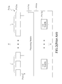
- FIG. 1 is a block diagram showing a first conventional ultrasound imaging system. As shown in FIG. 1 , the ultrasound imaging system PA 1 is electrically connected to an ultrasound probe PA 2 , the ultrasound probe PA 2 includes M channels PA 21 (only one is labelled).
- the ultrasound imaging system PA 1 includes a processing module PA 11 and M analog-to-digital (A/D) modules PA 12 , wherein the processing module PA 11 receives the echo signals PAS 1 from the M channels PA 21 , transforms the echo signals PAS 1 of the M channels PA 21 into digital signals by using the A/D modules PA 12 (the number of the channels PA 21 is identical to the number of the A/D modules PA 12 , that is, if M is 128, the number of the A/D modules PA 12 would be also 128 ), and proceeds linear and non-linear delay calculations to the digitalized echo signals and then accumulates the calculated results.
- A/D analog-to-digital
- the amount of delay can be represented as ⁇ (xi*sin ⁇ /c)+(((xi) 2 *cos 2 ⁇ )/(2*R*c)), wherein the part ⁇ (xi*sin ⁇ /c) represents linear steering delay, and the part (((xi) 2 *cos 2 ⁇ )/(2*R*c)) represents non-linear focusing delay, wherein xi is the distance between the channel of the ultrasound probe PA 2 and the central channel, R is the distance between the object to be detected and the central channel of the ultrasound probe PA 2 , ⁇ is the angle between R and the central channel of the ultrasound probe PA 2 , and c is the sound wave speed.
- FIG. 2 is a block diagram of a second conventional ultrasound imaging system.
- the ultrasound imaging system PA 1 a is also electrically connected to an ultrasound probe PA 2 a
- the ultrasound imaging system PA 1 a includes a processing module PA 11 a and m A/D modules PA 12 a , wherein the processing module PA 11 a receives the signals from the M channels and divides the signals into m groups, and each group includes the echo signals PAS 1 a received by n channels.
- the linear steering delays are applied to the signals and then the delayed signals are summed and transmitted to the m A/D modules PA 12 a (the number of the A/D modules is identical to the number of the groups, that is, if M is 128, m is 32, and n is 4, the number of the A/D modules would be 32). Thereafter, the non-linear focusing delays are applied to the pre-summed signals and then accumulating calculations are applied to the signals in the digital system to reconstruct the image.
- the circuit design as mentioned above can reduce the number of A/D modules PA 12 a effectively, but will have the problem of degrading system resolution and image quality.
- an image compensation system and a method thereof is provided in the present invention, which mainly features the technology of compensating the echo signal by using the digitalized plus-or-minus operators, arithmetic mean, and average signal strength value to achieve the object of reducing the number of A/D modules with acceptable image quality
- an image compensation system is provided in accordance with an embodiment of the present invention.
- the image compensation system is electrically connected to an ultrasound probe for compensating a plurality of echo signals received by the ultrasound probe.
- the ultrasound probe includes M channels divided into m groups, and each of the groups includes n channels.
- the image compensation system comprises an average value calculation module, an error value calculation module, an average error value calculation module, K first analog-to-digital (A/D) modules, m second A/D modules corresponding to the m groups, m third A/D modules corresponding to the m groups, and a processing module.
- the average value calculation module is electrically connected to the ultrasound probe for receiving the echo signals from the n channels of each of the groups to generate n signal strengths corresponding to the n echo signals at a parsing time, accumulating the n signal strengths to generate an accumulated signal strength, and dividing the accumulated signal strength by n to generate an average signal strength value corresponding to each of the groups.
- the error value calculation module is electrically connected to the average value calculation module for receiving the average signal strength value of each of the groups and the n signal strengths to generate n error values, and deciding n plus-or-minus operators corresponding to each of the groups according to positive or negative corresponding to the n error values respectively.
- the average error value calculation module is electrically connected to the error value calculation module for receiving the n error values corresponding to each of the groups, generating n absolute error values corresponding to the n error values respectively, calculating an arithmetic mean of the n absolute error value, and defining the arithmetic mean as an average absolute error value corresponding to each of the groups.
- Each of the first A/D modules includes N pins and is electrically connected to the error value calculation module for receiving the n plus-or-minus operators to transform the n plus-or-minus operators into n digitalized plus-or-minus operators respectively corresponding to each of the groups.
- Each of the second A/D modules is electrically connected to the average error value calculation module for receiving the average absolute error value corresponding to each of the groups for transforming the average absolute error value into a digitalized average absolute error value corresponding to each of the groups.
- Each of the third A/D modules is electrically connected to the average value calculation module for receiving the average signal strength value corresponding to each of the groups for transforming the average signal strength value into a digitalized average signal strength value corresponding to each of the groups.
- the processing module is electrically connected to the K first A/D modules, the m second A/D modules, and the m third A/D modules, for calculating n compensated echo signals of each of the groups according to the n digitalized plus-or-minus operators, the digitalized average absolute error value and the digitalized average signal strength value.
- K is an integer of rounding up M/N, and K+(m)+(m) ⁇ M.
- the image compensation system further comprises a receiving module, which is electrically connected between the ultrasound probe and the average value calculation module, and is also electrically connected to the error value calculation module for receiving the n echo signals from the n channels of each of the groups at the parsing time.
- the average error value calculation module calculates the arithmetic mean by using minimum mean square error (MMSE) estimation, and the K first A/D modules, the m second A/D module, and the m third A/D modules are A/D converters.
- MMSE minimum mean square error
- each of the n plus-or-minus operators is a plus operator or a minus operator.
- the digitalized plus-or-minus operator of the n digitalized plus-or-minus operators corresponding to the one of the n plus-or-minus operators corresponding to the plus operator is 1.
- the digitalized plus-or-minus operator of the n digitalized plus-or-minus operators corresponding to the one of the n plus-or-minus operators corresponding to the minus operator is 0.
- an image compensation method is also provided in accordance with an embodiment of the present invention.
- the image compensation method is applied to the above mentioned image compensation system and an ultrasound probe connected thereto, for compensating a plurality of echo signals received by the ultrasound probe.
- the ultrasound probe includes M channels divided into m groups, and each of the groups includes n channels.
- the image compensation method comprises steps (a) to (e).
- Step (a) is to receive the echo signals from the n channels of each of the groups to generate n signal strengths corresponding to the n echo signals at a parsing time, accumulate the n signal strengths to generate an accumulated signal strength, and divide the accumulated signal strength by n to generate an average signal strength value corresponding to each of the groups.
- Step (b) is to receive the average signal strength value of each of the groups and the n signal strengths to generate n error values, and decide n plus-or-minus operators corresponding to each of the groups according to positive or negative corresponding to the n error values respectively.
- Step (c) is to receive the n error values corresponding to each of the groups, generate n absolute error values corresponding to the n error values respectively, calculate an arithmetic mean of the n absolute error value, and define the arithmetic mean as an average absolute error value corresponding to each of the groups.
- Step (d) is to receive the n plus-or-minus operators, the average absolute error value corresponding to each of the groups, and the average signal strength value corresponding to each of the groups, to transform the n plus-or-minus operators, the average absolute error value corresponding to each of the groups, and the average signal strength value corresponding to each of the groups into n digitalized plus-or-minus operators corresponding to each of the groups, a digitalized average absolute error value, and a digitalized average signal strength value.
- Step (e) is to calculate n compensated echo signals of each of the groups according to the n digitalized plus-or-minus operators, the digitalized average absolute error value, and the digitalized average signal strength value.
- K is an integer of rounding up M/N, and K+(m)+(m) ⁇ M.
- each of the n plus-or-minus operators is a plus operator or a minus operator.
- the digitalized plus-or-minus operator of the n digitalized plus-or-minus operators corresponding to the one of the n plus-or-minus operators corresponding to the plus operator is 1.
- the digitalized plus-or-minus operator of the n digitalized plus-or-minus operators corresponding to the one of the n plus-or-minus operators corresponding to the minus operator is 0.
- the number of A/D modules can be significantly reduced because the echo signal is compensated by using the digitalized plus-or-minus operators, arithmetic mean, and average signal strength value, and the distorted image can be effectively compensated during image processing procedures, such that image quality can be effectively enhanced to facilitate practical usage.
- FIG. 1 is a block diagram of a first conventional ultrasound imaging system.
- FIG. 2 is a block diagram of a second conventional ultrasound imaging system.
- FIG. 3 is a block diagram of an image compensation system in accordance with a preferred embodiment of the present invention.
- FIG. 4 is a flow chart showing an image compensation method in accordance with a preferred embodiment of the present invention.
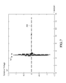
- FIG. 5 to FIG. 8 are schematic diagrams showing the waveforms of the echo signal in accordance with a preferred embodiment of the present invention.
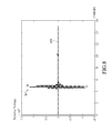
- FIG. 9 to FIG. 12 are schematic diagrams showing the waveforms of the compensated echo signal in accordance with a preferred embodiment of the present invention.
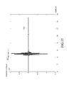
- FIG. 13 is a schematic diagram showing the compensated echo signal of the second conventional ultrasound imaging system.
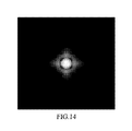
- FIG. 14 shows a simulation image by using the first conventional ultrasound imaging system.
- FIG. 15 shows a simulation image by using the second conventional ultrasound imaging system.
- FIG. 16 shows a simulation image by using the image compensation system in accordance with the preferred embodiment of the present invention.
- FIG. 3 is a block diagram of an image compensation system in accordance with a preferred embodiment of the present invention.
- the image compensation system 1 provided in accordance with the preferred embodiment of the present invention is electrically connected to an ultrasound probe 2 for compensating a plurality of echo signals S 1 received by the ultrasound probe 2 .
- the echo signal S 1 is defined as the reflection signal of an ultrasonic signal (not shown in this figure) from the ultrasound probe 2 to an object to be detected (not shown in this figure).
- the ultrasound probe 2 can be a one-dimensional (1D) probe or a two-dimensional (2D) probe, and the 2D probe is preferred in practice.
- M can be 128, m can be 32, and n can be 4, however, the present invention is not so restricted.
- the image compensation system 1 comprises a receiving module 11 , an average value calculation module 12 , an error value calculation module 13 , an average error value calculation module 14 , K first analog-to-digital (A/D) modules 15 (only one of them is labelled in the figure), m second A/D modules 16 (only one of them is labelled) corresponding to the above mentioned m groups, m third A/D modules 17 (only one of them is labelled) corresponding to the above mentioned m groups, and a processing module 18 .
- A/D analog-to-digital
- the receiving module 11 is electrically connected to the ultrasound probe 2 .
- the receiving module 11 may be composed of the typical ultrasound probe processing circuit.
- the average value calculation module 12 is electrically connected to the receiving module 11 and can be composed of the typical operational amplifier (such as an averaging circuit) and some other components, however, the present invention is not so restricted.
- the error value calculation module 13 is electrically connected to the receiving module 11 and the average value calculation module 12 and can be composed of the subtractor, the comparator, etc., however, the present invention is not so restricted.
- the average error value calculation module 14 is electrically connected to the error value calculation module 13 and can be composed of the full-wave rectifier and the operational amplifier, however, the present invention is not so restricted.
- Each first A/D module 15 includes N pins (for example, N is 16 in the preferred embodiment of the present invention) and is electrically connected to the error value calculation module 13 .
- the second A/D module 16 is electrically connected to the average error value calculation module 14
- the third A/D module 17 is electrically connected to the average value calculation module 12
- the above mentioned K first A/D module 15 , the above mentioned m second A/D modules 16 and the above mentioned m third A/D modules 17 can be an analog-to-digital convertor.
- the processing module 18 may be implemented by using the existed digital system to execute calculation of digital values.
- the processing module 18 may include a storage unit 181 and a processing unit 182 , wherein the storage unit 181 can be a typical memory, and the processing module 182 electrically connected to the storage unit 181 can be a typical processor.
- FIGS. 3 to 8 wherein FIG. 4 is a flow chart showing an image compensation method in accordance with a preferred embodiment of the present invention, and FIGS. 5 to 8 are schematic diagrams showing the waveforms of the echo signal in accordance with a preferred embodiment of the present invention.
- the image compensation method comprises the following steps:
- Step S 101 is to receive the echo signals from the n channels of each of the groups to generate n signal strengths corresponding to the n echo signals at a parsing time, accumulate the n signal strengths to generate an accumulated signal strength, and divide the accumulated signal strength by n to generate an average signal strength value corresponding to each of the groups.
- Step S 102 is to receive the average signal strength value of each of the groups and the n signal strengths to generate n error values, and decide n plus-or-minus operators corresponding to each of the groups according to positive or negative corresponding to the n error values respectively.
- Step S 103 is to receive the n error values corresponding to each of the groups, generate n absolute error values corresponding to the n error values respectively, calculate an arithmetic mean of the n absolute error value, and define the arithmetic mean as an average absolute error value corresponding to each of the groups.
- Step S 104 is to receive the n plus-or-minus operators, the average absolute error value corresponding to each of the groups, and the average signal strength value corresponding to each of the groups, to transform the n plus-or-minus operators, the average absolute error value corresponding to each of the groups, and the average signal strength value corresponding to each of the groups into n digitalized plus-or-minus operators corresponding to each of the groups, a digitalized average absolute error value, and a digitalized average signal strength value.
- Step S 105 is to calculate n compensated echo signals of each of the groups according to the n digitalized plus-or-minus operators, the digitalized average absolute error value and the digitalized average signal strength value.
- Step S 101 the receiving module 11 is utilized for receiving the n echo signals of the plurality of echo signals S 1 from the n channels 21 at a parsing time.
- these echo signals S 1 can be the steered signals (or the un-steered ones which would be steered in the receiving module 11 ), such as those being applied with delaying operation.
- the parsing time can be 0 microsecond, 2 microsecond, 4 microsecond, and so on to 16 microsecond shown in FIG. 5 to FIG. 8 (it is preferred to use the parsing time second decimal digitals as the unit, such as 0.12 microsecond, thus, steps S 101 to S 105 of the present invention is for dealing with the echo signals of different parsing time), however, the present invention is not so restricted.
- the receiving module 11 receives the above mentioned n echo signals S 1 to the average value calculation module 12 .
- the average value calculation module 12 receives the n echo signals 21 of these echo signals S 1 from the n channels 21 to generate n signal strengths corresponding to the n echo signals at the parsing time, accumulates the n signal strengths to generate an accumulated signal strength, and divides the accumulated signal strength by n to generate an average signal strength value corresponding to each of the groups.
- the step S 101 can be implemented by using the averaging circuit.
- n 4
- there would be four echo signals S 1 represented by waveforms 100 , 200 , 300 , and 400 in FIGS. 5 to 8 respectively, and it should be noted that the initial time of the first wave corresponding to the widths W 1 , W 2 , W 3 , and W 4 is 4.68 microsecond, the end time of the fourth wave is 5.64 microsecond, and thus the widths W 1 , W 2 , W 3 , and W 4 are 0.96 microsecond).
- the average value calculation module 12 generates four signals strengths (i.e. voltage value or current value of each point in the signal waveform, and the four signal strengths are represented as A, B, C, and D) after receiving the four echo signals S 1 .
- the average value calculation module 12 accumulates the signal strengths directly to access the accumulated signal strength (each point in the signal waveform has a corresponding accumulated signal strength), and then divides the accumulated signal strength by 4 to access the average signal strength value (each point in the signal waveform has a corresponding average signal strength value, which is represented as DS).
- step S 102 the error value calculation module 13 receives the average signal strength value DS corresponding to each of the groups and the above mentioned n signal strengths A, B, C, and D to generate n error values (represented as Da, Db, Dc, and Dd in the following paragraphs), and decides n plus-or-minus operators corresponding to each of the groups according to positive or negative corresponding to the n error values respectively.
- n error values represented as Da, Db, Dc, and Dd in the following paragraphs
- Each of the aforementioned plus-or-minus operator is a plus operator or a minus operator (which may be implemented by using a comparator for example).
- the error value calculation module 13 may use the subtractors to execute the above mentioned calculations.
- the four plus-or-minus operators corresponding to each of the groups are decided according to positive or negative of the above mentioned error values Da, Db, Dc, and Dd. For example, if the error value Da is positive, the error value Db is positive, the error value Dc is negative, and the error value Dd is negative, then the corresponding plus-or-minus operators would be plus, plus, minus, and minus respectively.
- the average error value calculation module 14 receives the n error values corresponding to each of the groups, and generates n absolute error values corresponding to the n error values respectively.
- the n absolute error value can be generated by using an absolute value calculator.
- an arithmetic mean of the n absolute error value may be further calculated and defined as an average absolute error value corresponding to each of the groups. The arithmetic mean can be calculated by using an average calculator.
- the average error value calculation module 14 receives the four error values Da, Db, Dc, and Dd, calculates four corresponding absolute error values
- each of the first A/D modules 15 receives the above mentioned n plus-or-minus operators to transform the n plus-or-minus operators into n digitalized plus-or-minus operators respectively corresponding to each of the groups.
- the digitalized plus-or-minus operator of the n digitalized plus-or-minus operators corresponding to the one of the n plus-or-minus operators corresponding to the plus operator is 1.
- the present invention is not so restricted.
- the digitalized plus-or-minus operator of the n digitalized plus-or-minus operators corresponding to the one of the n plus-or-minus operators corresponding to the minus operator is 0.
- the present invention is not so restricted.
- the four digitalized plus-or-minus operators would be 1, 1, 0, and 0.
- Each of the second A/D modules 16 receives the average absolute error value corresponding to each of the groups for transforming the average absolute error value ED into a digitalized average absolute error value (represented as a in the following paragraphs) corresponding to each of the groups.
- Each of the third A/D modules 17 receives the average signal strength value corresponding to each of the groups for transforming the average signal strength value into a digitalized average signal strength value (represented as b in the following paragraphs) corresponding to each of the groups.
- the above mentioned digitalized processing may reduce distortion during signal processing so as to reduce distortion in the following image compensation step.
- step S 105 the storage unit 181 of the processing module 18 stores the n digitalized plus-or-minus operators corresponding to each of the groups, the digitalized average absolute error value corresponding to each of the groups, and the digitalized average signal strength value corresponding to each of the groups.
- the processing unit 182 fetches the n digitalized plus-or-minus operators corresponding to each of the groups, the digitalized average absolute error value corresponding to each of the groups and the digitalized average signal strength value corresponding to each of the groups in the storage unit 181 , and calculates n compensated echo signals (represented as A′, B′, C′ and D′ in the following paragraphs) for each of the groups according to the n digitalized plus-or-minus operators, the digitalized average absolute error value, and the digitalized average signal strength value.
- the compensated echo signal A′ can be b+a
- the compensated echo signal B′ can be b+a
- the compensation signal C′ can be b ⁇ a
- the compensated echo signal D′ can be b ⁇ a.
- the number n can be any integer according to the need.
- the present invention has the potential to reduce the number of A/D modules effectively.
- FIGS. 9 to 13 are schematic diagrams showing the waveforms of the compensated echo signal in accordance with a preferred embodiment of the present invention
- FIG. 13 is a schematic diagram showing the compensated echo signal of the second conventional ultrasound imaging system.
- the compensated simulation result of each of the parsing time after the calculations of steps S 101 to S 105 would generate the waveforms 500 , 600 , 700 , and 800 corresponding to the four echo signals S 1 (waveforms 100 , 200 , 300 , and 400 ) respectively.
- the initial time of the first wave of the width W 5 , W 6 , W 7 , and W 8 is 4.58 microsecond
- the end time of the sixth wave is 5.74
- the widths W 5 , W 6 , W 7 , and W 8 are 1.16 microseconds.
- the waveforms generated by using the first conventional technology are similar to the waveforms 100 , 200 , 300 , and 400 (the term “similar” described in the preferred embodiment of the present invention indicates that the calculated result is within the acceptable error margin), and the waveforms 500 , 600 , 700 , and 800 generated by using the image compensation system and the compensation method thereof provided in the present invention are similar to the waveforms 100 , 200 , 300 , and 400 , and the widths W 5 , W 6 , W 7 , and W 8 thereof are not much different from the widths W 1 , W 2 , W 3 , and W 4 , therefore, in compared with the first conventional technology, which needs a great number of A/D modules, the present invention needs fewer A/D modules but is able to maintain the image quality to the level close to the first conventional technology.
- the waveform 900 shown in FIG. 13 is the compensated result after the calculation of the second conventional technology, wherein the initial time of the first wave of the width W 9 is 4.42 microsecond, the end time of the sixth wave is 5.82 microsecond, and thus the width is 1.4 microsecond, which is much longer than that of the preferred embodiment of the present invention, i.e. 1.16 microsecond.
- the second conventional technology has the problems of a significant amount of noise and poor resolution although it uses fewer A/D modules.
- the technology of the present invention applies the relation K+(m)+(m) ⁇ M to define an adequate number of A/D modules such that the problem of poor resolution can be properly resolved.
- FIGS. 14 to 16 show a simulation image by using the first conventional ultrasound imaging system
- FIG. 15 shows a simulation image by using the second conventional ultrasound imaging system
- FIG. 16 shows a simulation image by using the image compensation system provided in accordance with the preferred embodiment of the present invention.
- the image resolution using the present invention is close to that using the first conventional technology but much better than that using the second conventional technology.
- the technology provided in the present invention the number of A/D modules can be significantly reduced in compared with the first conventional technology while maintaining acceptable image resolution.
- the technology described in the preferred embodiment of the present invention should be able to be applied to the case with 2D ultrasound probe or more.
- the number of A/D modules can be significantly reduced because the echo signal is compensated by using the digitalized plus-or-minus operators, arithmetic mean, and average signal strength value, and the distorted image can be effectively compensated during image processing procedures, such that image quality can be effectively enhanced to facilitate the practical usage.
Landscapes
- Engineering & Computer Science (AREA)
- Health & Medical Sciences (AREA)
- Life Sciences & Earth Sciences (AREA)
- Physics & Mathematics (AREA)
- Remote Sensing (AREA)
- Radar, Positioning & Navigation (AREA)
- Molecular Biology (AREA)
- General Health & Medical Sciences (AREA)
- Radiology & Medical Imaging (AREA)
- Biomedical Technology (AREA)
- Heart & Thoracic Surgery (AREA)
- Medical Informatics (AREA)
- Nuclear Medicine, Radiotherapy & Molecular Imaging (AREA)
- Surgery (AREA)
- Animal Behavior & Ethology (AREA)
- Pathology (AREA)
- Public Health (AREA)
- Veterinary Medicine (AREA)
- Biophysics (AREA)
- General Physics & Mathematics (AREA)
- Computer Networks & Wireless Communication (AREA)
- Computer Vision & Pattern Recognition (AREA)
- Acoustics & Sound (AREA)
- Ultra Sonic Daignosis Equipment (AREA)
Abstract
An image compensation system and method which provided to compensate echo signals acquired from an ultrasound probe which are provided in the present invention. M channels of the ultrasound probe are divided into m groups where each group consists of n channels. For each group, image compensation system takes the average value from n channel data to achieve an average-signal strength echo signal and then computes n error values according to the average-signal strength echo signal and n echo signals within a group. The image compensation system determines n plus and minus sign operators according to the positivity or negativity of the n error values. The image compensation system then calculates a mean absolute error value according to the n error values. Thereafter, n compensated echo signals of the m groups according to the average-signal echo strength, plus and minus sign operators, and the mean absolute error value are digitized.
Description
- This application claims the benefit of Taiwan Patent Application Serial No. 105132392, filed Oct. 6, 2016, the subject matter of which is incorporated herein by reference.
- The present invention is related to an image compensation system and a method thereof, and more particularly is related to the image compensation system and the method thereof which compensate echo signals by using plus-or-minus operators, arithmetic mean, and average signal strength value.
- Ultrasound imaging has been widely applied to medical diagnosis. Compared to other clinical medical imaging modalities such as X-ray, CT, MRI and nuclear imaging systems, ultrasound imaging is characterized as cost effective, non-invasive, free of ionizing radiation, real-time, portable, capability of flow detection, etc. Hence, ultrasound imaging has been widely utilized to assist clinical diagnosis. Ultrasound imaging is based on reflection and backscattering. Specifically, a probe is required for radiating a sound wave into a human body. The interaction between sound wave and the tissues inside the human body produces echoes that are detected by the probe and images are reconstructed by the system based on the received echoes.
- The imaging process of ultrasound imaging needs a calculation circuit as shown in
FIG. 1 .FIG. 1 is a block diagram showing a first conventional ultrasound imaging system. As shown inFIG. 1 , the ultrasound imaging system PA1 is electrically connected to an ultrasound probe PA2, the ultrasound probe PA2 includes M channels PA21 (only one is labelled). - The ultrasound imaging system PA1 includes a processing module PA11 and M analog-to-digital (A/D) modules PA12, wherein the processing module PA11 receives the echo signals PAS1 from the M channels PA21, transforms the echo signals PAS1 of the M channels PA21 into digital signals by using the A/D modules PA12 (the number of the channels PA21 is identical to the number of the A/D modules PA12, that is, if M is 128, the number of the A/D modules PA12 would be also 128), and proceeds linear and non-linear delay calculations to the digitalized echo signals and then accumulates the calculated results. The amount of delay can be represented as −(xi*sin θ/c)+(((xi)2*cos2 θ)/(2*R*c)), wherein the part −(xi*sin θ/c) represents linear steering delay, and the part (((xi)2*cos2 θ)/(2*R*c)) represents non-linear focusing delay, wherein xi is the distance between the channel of the ultrasound probe PA2 and the central channel, R is the distance between the object to be detected and the central channel of the ultrasound probe PA2, θ is the angle between R and the central channel of the ultrasound probe PA2, and c is the sound wave speed.
- The circuit design as mentioned above has the potential to achieve better image imaging quality, however, because the number of the A/D modules PA12 should be identical to the number of the channels PA21, the increasing number of channels may result in high cost and high complexity of circuit design of the ultrasound imaging system PA1, and a significant space may be needed for locating the circuit of the ultrasound imaging system PA1.
FIG. 2 is a block diagram of a second conventional ultrasound imaging system. As shown, the ultrasound imaging system PA1 a is also electrically connected to an ultrasound probe PA2 a, the ultrasound probe PA2 a includes M channels PA21 a (only one of them is labelled) divided into m groups in general, and each group includes n channels (i.e. m*n=M). - The ultrasound imaging system PA1 a includes a processing module PA11 a and m A/D modules PA12 a, wherein the processing module PA11 a receives the signals from the M channels and divides the signals into m groups, and each group includes the echo signals PAS1 a received by n channels. The linear steering delays are applied to the signals and then the delayed signals are summed and transmitted to the m A/D modules PA12 a (the number of the A/D modules is identical to the number of the groups, that is, if M is 128, m is 32, and n is 4, the number of the A/D modules would be 32). Thereafter, the non-linear focusing delays are applied to the pre-summed signals and then accumulating calculations are applied to the signals in the digital system to reconstruct the image.
- The circuit design as mentioned above can reduce the number of A/D modules PA12 a effectively, but will have the problem of degrading system resolution and image quality.
- In view of the conventional ultrasound imaging system, it is common to have the problem regarding tradeoff between the number of channels (each channel accompanies one A/D module and system complexity increases as the channel counts increased image quality. Accordingly, an image compensation system and a method thereof is provided in the present invention, which mainly features the technology of compensating the echo signal by using the digitalized plus-or-minus operators, arithmetic mean, and average signal strength value to achieve the object of reducing the number of A/D modules with acceptable image quality
- According to the above mentioned object, an image compensation system is provided in accordance with an embodiment of the present invention. The image compensation system is electrically connected to an ultrasound probe for compensating a plurality of echo signals received by the ultrasound probe. The ultrasound probe includes M channels divided into m groups, and each of the groups includes n channels. The image compensation system comprises an average value calculation module, an error value calculation module, an average error value calculation module, K first analog-to-digital (A/D) modules, m second A/D modules corresponding to the m groups, m third A/D modules corresponding to the m groups, and a processing module. The average value calculation module is electrically connected to the ultrasound probe for receiving the echo signals from the n channels of each of the groups to generate n signal strengths corresponding to the n echo signals at a parsing time, accumulating the n signal strengths to generate an accumulated signal strength, and dividing the accumulated signal strength by n to generate an average signal strength value corresponding to each of the groups.
- The error value calculation module is electrically connected to the average value calculation module for receiving the average signal strength value of each of the groups and the n signal strengths to generate n error values, and deciding n plus-or-minus operators corresponding to each of the groups according to positive or negative corresponding to the n error values respectively. The average error value calculation module is electrically connected to the error value calculation module for receiving the n error values corresponding to each of the groups, generating n absolute error values corresponding to the n error values respectively, calculating an arithmetic mean of the n absolute error value, and defining the arithmetic mean as an average absolute error value corresponding to each of the groups. Each of the first A/D modules includes N pins and is electrically connected to the error value calculation module for receiving the n plus-or-minus operators to transform the n plus-or-minus operators into n digitalized plus-or-minus operators respectively corresponding to each of the groups.
- Each of the second A/D modules is electrically connected to the average error value calculation module for receiving the average absolute error value corresponding to each of the groups for transforming the average absolute error value into a digitalized average absolute error value corresponding to each of the groups. Each of the third A/D modules is electrically connected to the average value calculation module for receiving the average signal strength value corresponding to each of the groups for transforming the average signal strength value into a digitalized average signal strength value corresponding to each of the groups. The processing module is electrically connected to the K first A/D modules, the m second A/D modules, and the m third A/D modules, for calculating n compensated echo signals of each of the groups according to the n digitalized plus-or-minus operators, the digitalized average absolute error value and the digitalized average signal strength value. Wherein, K is an integer of rounding up M/N, and K+(m)+(m)<M.
- In accordance with an embodiment of the present invention, the image compensation system further comprises a receiving module, which is electrically connected between the ultrasound probe and the average value calculation module, and is also electrically connected to the error value calculation module for receiving the n echo signals from the n channels of each of the groups at the parsing time. In addition, in accordance with an embodiment of the present invention, the average error value calculation module calculates the arithmetic mean by using minimum mean square error (MMSE) estimation, and the K first A/D modules, the m second A/D module, and the m third A/D modules are A/D converters. In addition, in accordance with an embodiment of the image compensation system of the present invention, each of the n plus-or-minus operators is a plus operator or a minus operator. As one of the n plus-or-minus operators is the plus operator, the digitalized plus-or-minus operator of the n digitalized plus-or-minus operators corresponding to the one of the n plus-or-minus operators corresponding to the plus operator is 1. As one of the n plus-or-minus operators is the minus operator, the digitalized plus-or-minus operator of the n digitalized plus-or-minus operators corresponding to the one of the n plus-or-minus operators corresponding to the minus operator is 0.
- According to the above mentioned object, an image compensation method is also provided in accordance with an embodiment of the present invention. The image compensation method is applied to the above mentioned image compensation system and an ultrasound probe connected thereto, for compensating a plurality of echo signals received by the ultrasound probe. The ultrasound probe includes M channels divided into m groups, and each of the groups includes n channels. The image compensation method comprises steps (a) to (e). Step (a) is to receive the echo signals from the n channels of each of the groups to generate n signal strengths corresponding to the n echo signals at a parsing time, accumulate the n signal strengths to generate an accumulated signal strength, and divide the accumulated signal strength by n to generate an average signal strength value corresponding to each of the groups. Step (b) is to receive the average signal strength value of each of the groups and the n signal strengths to generate n error values, and decide n plus-or-minus operators corresponding to each of the groups according to positive or negative corresponding to the n error values respectively. Step (c) is to receive the n error values corresponding to each of the groups, generate n absolute error values corresponding to the n error values respectively, calculate an arithmetic mean of the n absolute error value, and define the arithmetic mean as an average absolute error value corresponding to each of the groups.
- Step (d) is to receive the n plus-or-minus operators, the average absolute error value corresponding to each of the groups, and the average signal strength value corresponding to each of the groups, to transform the n plus-or-minus operators, the average absolute error value corresponding to each of the groups, and the average signal strength value corresponding to each of the groups into n digitalized plus-or-minus operators corresponding to each of the groups, a digitalized average absolute error value, and a digitalized average signal strength value. Step (e) is to calculate n compensated echo signals of each of the groups according to the n digitalized plus-or-minus operators, the digitalized average absolute error value, and the digitalized average signal strength value. Wherein, K is an integer of rounding up M/N, and K+(m)+(m)<M.
- In accordance with an embodiment of the image compensation method of the present invention, each of the n plus-or-minus operators is a plus operator or a minus operator. As one of the n plus-or-minus operators is the plus operator, the digitalized plus-or-minus operator of the n digitalized plus-or-minus operators corresponding to the one of the n plus-or-minus operators corresponding to the plus operator is 1. As one of the n plus-or-minus operators is the minus operator, the digitalized plus-or-minus operator of the n digitalized plus-or-minus operators corresponding to the one of the n plus-or-minus operators corresponding to the minus operator is 0.
- By using the image compensation system and the compensation method thereof provided in the embodiment of the present invention, the number of A/D modules can be significantly reduced because the echo signal is compensated by using the digitalized plus-or-minus operators, arithmetic mean, and average signal strength value, and the distorted image can be effectively compensated during image processing procedures, such that image quality can be effectively enhanced to facilitate practical usage.
- The present invention will now be specified with reference to its preferred embodiment illustrated in the drawings, in which:
-
FIG. 1 is a block diagram of a first conventional ultrasound imaging system. -
FIG. 2 is a block diagram of a second conventional ultrasound imaging system. -
FIG. 3 is a block diagram of an image compensation system in accordance with a preferred embodiment of the present invention. -
FIG. 4 is a flow chart showing an image compensation method in accordance with a preferred embodiment of the present invention. -
FIG. 5 toFIG. 8 are schematic diagrams showing the waveforms of the echo signal in accordance with a preferred embodiment of the present invention. -
FIG. 9 toFIG. 12 are schematic diagrams showing the waveforms of the compensated echo signal in accordance with a preferred embodiment of the present invention. -
FIG. 13 is a schematic diagram showing the compensated echo signal of the second conventional ultrasound imaging system. -
FIG. 14 shows a simulation image by using the first conventional ultrasound imaging system. -
FIG. 15 shows a simulation image by using the second conventional ultrasound imaging system. -
FIG. 16 shows a simulation image by using the image compensation system in accordance with the preferred embodiment of the present invention. - There are various embodiments of the image compensation system and the method thereof in accordance with the present invention, which are not repeated hereby. Only one preferred embodiment is mentioned in the following paragraph as an example.
- Please refer to
FIG. 3 , which is a block diagram of an image compensation system in accordance with a preferred embodiment of the present invention. As shown, theimage compensation system 1 provided in accordance with the preferred embodiment of the present invention is electrically connected to anultrasound probe 2 for compensating a plurality of echo signals S1 received by theultrasound probe 2. The echo signal S1 is defined as the reflection signal of an ultrasonic signal (not shown in this figure) from theultrasound probe 2 to an object to be detected (not shown in this figure). Theultrasound probe 2 includesM channels 21, theM channels 21 are divided into m groups, and each of the groups includes n channels 21 (only one of them is labelled in the figure), i.e. m*n=M. As a preferred embodiment of the present invention, theultrasound probe 2 can be a one-dimensional (1D) probe or a two-dimensional (2D) probe, and the 2D probe is preferred in practice. As a preferred embodiment of the present invention, for example, M can be 128, m can be 32, and n can be 4, however, the present invention is not so restricted. - The
image compensation system 1 comprises a receivingmodule 11, an averagevalue calculation module 12, an errorvalue calculation module 13, an average errorvalue calculation module 14, K first analog-to-digital (A/D) modules 15 (only one of them is labelled in the figure), m second A/D modules 16 (only one of them is labelled) corresponding to the above mentioned m groups, m third A/D modules 17 (only one of them is labelled) corresponding to the above mentioned m groups, and aprocessing module 18. - The receiving
module 11 is electrically connected to theultrasound probe 2. In general, the receivingmodule 11 may be composed of the typical ultrasound probe processing circuit. The averagevalue calculation module 12 is electrically connected to the receivingmodule 11 and can be composed of the typical operational amplifier (such as an averaging circuit) and some other components, however, the present invention is not so restricted. The errorvalue calculation module 13 is electrically connected to the receivingmodule 11 and the averagevalue calculation module 12 and can be composed of the subtractor, the comparator, etc., however, the present invention is not so restricted. The average errorvalue calculation module 14 is electrically connected to the errorvalue calculation module 13 and can be composed of the full-wave rectifier and the operational amplifier, however, the present invention is not so restricted. - Each first A/
D module 15 includes N pins (for example, N is 16 in the preferred embodiment of the present invention) and is electrically connected to the errorvalue calculation module 13. The second A/D module 16 is electrically connected to the average errorvalue calculation module 14, the third A/D module 17 is electrically connected to the averagevalue calculation module 12, and the above mentioned K first A/D module 15, the above mentioned m second A/D modules 16 and the above mentioned m third A/D modules 17 can be an analog-to-digital convertor. - The
processing module 18 may be implemented by using the existed digital system to execute calculation of digital values. Theprocessing module 18 may include astorage unit 181 and aprocessing unit 182, wherein thestorage unit 181 can be a typical memory, and theprocessing module 182 electrically connected to thestorage unit 181 can be a typical processor. - For a better understanding of the operation of the
image compensation system 1, please refer toFIGS. 3 to 8 , whereinFIG. 4 is a flow chart showing an image compensation method in accordance with a preferred embodiment of the present invention, andFIGS. 5 to 8 are schematic diagrams showing the waveforms of the echo signal in accordance with a preferred embodiment of the present invention. As shown, the image compensation method comprises the following steps: - Step S101 is to receive the echo signals from the n channels of each of the groups to generate n signal strengths corresponding to the n echo signals at a parsing time, accumulate the n signal strengths to generate an accumulated signal strength, and divide the accumulated signal strength by n to generate an average signal strength value corresponding to each of the groups.
- Step S102 is to receive the average signal strength value of each of the groups and the n signal strengths to generate n error values, and decide n plus-or-minus operators corresponding to each of the groups according to positive or negative corresponding to the n error values respectively.
- Step S103 is to receive the n error values corresponding to each of the groups, generate n absolute error values corresponding to the n error values respectively, calculate an arithmetic mean of the n absolute error value, and define the arithmetic mean as an average absolute error value corresponding to each of the groups.
- Step S104 is to receive the n plus-or-minus operators, the average absolute error value corresponding to each of the groups, and the average signal strength value corresponding to each of the groups, to transform the n plus-or-minus operators, the average absolute error value corresponding to each of the groups, and the average signal strength value corresponding to each of the groups into n digitalized plus-or-minus operators corresponding to each of the groups, a digitalized average absolute error value, and a digitalized average signal strength value.
- Step S105 is to calculate n compensated echo signals of each of the groups according to the n digitalized plus-or-minus operators, the digitalized average absolute error value and the digitalized average signal strength value.
- In Step S101, the receiving
module 11 is utilized for receiving the n echo signals of the plurality of echo signals S1 from then channels 21 at a parsing time. It should be noted that these echo signals S1 can be the steered signals (or the un-steered ones which would be steered in the receiving module 11), such as those being applied with delaying operation. The parsing time can be 0 microsecond, 2 microsecond, 4 microsecond, and so on to 16 microsecond shown inFIG. 5 toFIG. 8 (it is preferred to use the parsing time second decimal digitals as the unit, such as 0.12 microsecond, thus, steps S101 to S105 of the present invention is for dealing with the echo signals of different parsing time), however, the present invention is not so restricted. - In addition, the receiving
module 11 receives the above mentioned n echo signals S1 to the averagevalue calculation module 12. The averagevalue calculation module 12 receives the n echo signals 21 of these echo signals S1 from then channels 21 to generate n signal strengths corresponding to the n echo signals at the parsing time, accumulates the n signal strengths to generate an accumulated signal strength, and divides the accumulated signal strength by n to generate an average signal strength value corresponding to each of the groups. As a preferred embodiment, the step S101 can be implemented by using the averaging circuit. - For example, as a preferred embodiment of the present invention, if n is 4, there would be four echo signals S1 (represented by
waveforms FIGS. 5 to 8 respectively, and it should be noted that the initial time of the first wave corresponding to the widths W1, W2, W3, and W4 is 4.68 microsecond, the end time of the fourth wave is 5.64 microsecond, and thus the widths W1, W2, W3, and W4 are 0.96 microsecond). - The average
value calculation module 12 generates four signals strengths (i.e. voltage value or current value of each point in the signal waveform, and the four signal strengths are represented as A, B, C, and D) after receiving the four echo signals S1. The averagevalue calculation module 12 accumulates the signal strengths directly to access the accumulated signal strength (each point in the signal waveform has a corresponding accumulated signal strength), and then divides the accumulated signal strength by 4 to access the average signal strength value (each point in the signal waveform has a corresponding average signal strength value, which is represented as DS). - In step S102, the error
value calculation module 13 receives the average signal strength value DS corresponding to each of the groups and the above mentioned n signal strengths A, B, C, and D to generate n error values (represented as Da, Db, Dc, and Dd in the following paragraphs), and decides n plus-or-minus operators corresponding to each of the groups according to positive or negative corresponding to the n error values respectively. Each of the aforementioned plus-or-minus operator is a plus operator or a minus operator (which may be implemented by using a comparator for example). - For example, in accordance with the preferred embodiment of the present invention, in which n is 4, the error
value calculation module 13 may calculate the error values Da, Db, Dc, and Dd using the equations Da=DS-A, Db=DS-B, Dc=DS-C, and Dd=DS-D. Preferably, the errorvalue calculation module 13 may use the subtractors to execute the above mentioned calculations. Then, the four plus-or-minus operators corresponding to each of the groups are decided according to positive or negative of the above mentioned error values Da, Db, Dc, and Dd. For example, if the error value Da is positive, the error value Db is positive, the error value Dc is negative, and the error value Dd is negative, then the corresponding plus-or-minus operators would be plus, plus, minus, and minus respectively. - In step S103, the average error
value calculation module 14 receives the n error values corresponding to each of the groups, and generates n absolute error values corresponding to the n error values respectively. Preferably, the n absolute error value can be generated by using an absolute value calculator. After completing the above mentioned steps, an arithmetic mean of the n absolute error value may be further calculated and defined as an average absolute error value corresponding to each of the groups. The arithmetic mean can be calculated by using an average calculator. - For example, the average error
value calculation module 14 receives the four error values Da, Db, Dc, and Dd, calculates four corresponding absolute error values |Da|, |Db|, |Dc| and |Dd| by using the full-wave rectifier, and then calculates the arithmetic mean (which may be implemented by using the operational amplifier), e.g. (|Da|+|Db|+|Dc|+|Dd|)/4, which is defined as an average absolute error value (represented as ED in the following paragraphs) corresponding to each of the groups. - In step S104, each of the first A/
D modules 15 receives the above mentioned n plus-or-minus operators to transform the n plus-or-minus operators into n digitalized plus-or-minus operators respectively corresponding to each of the groups. As one of the n plus-or-minus operators is the plus operator, the digitalized plus-or-minus operator of the n digitalized plus-or-minus operators corresponding to the one of the n plus-or-minus operators corresponding to the plus operator is 1. However, the present invention is not so restricted. As one of the n plus-or-minus operators is the minus operator, the digitalized plus-or-minus operator of the n digitalized plus-or-minus operators corresponding to the one of the n plus-or-minus operators corresponding to the minus operator is 0. However, the present invention is not so restricted. As for the present preferred embodiment, in which n is 4, the four digitalized plus-or-minus operators would be 1, 1, 0, and 0. - Each of the second A/
D modules 16 receives the average absolute error value corresponding to each of the groups for transforming the average absolute error value ED into a digitalized average absolute error value (represented as a in the following paragraphs) corresponding to each of the groups. Each of the third A/D modules 17 receives the average signal strength value corresponding to each of the groups for transforming the average signal strength value into a digitalized average signal strength value (represented as b in the following paragraphs) corresponding to each of the groups. The above mentioned digitalized processing may reduce distortion during signal processing so as to reduce distortion in the following image compensation step. - In step S105, the
storage unit 181 of theprocessing module 18 stores the n digitalized plus-or-minus operators corresponding to each of the groups, the digitalized average absolute error value corresponding to each of the groups, and the digitalized average signal strength value corresponding to each of the groups. - The
processing unit 182 fetches the n digitalized plus-or-minus operators corresponding to each of the groups, the digitalized average absolute error value corresponding to each of the groups and the digitalized average signal strength value corresponding to each of the groups in thestorage unit 181, and calculates n compensated echo signals (represented as A′, B′, C′ and D′ in the following paragraphs) for each of the groups according to the n digitalized plus-or-minus operators, the digitalized average absolute error value, and the digitalized average signal strength value. As for the present preferred embodiment in which n is 4, the compensated echo signal A′ can be b+a, the compensated echo signal B′ can be b+a, the compensation signal C′ can be b−a, and the compensated echo signal D′ can be b−a. However, the present invention is not so restricted. The number n can be any integer according to the need. - In addition, it should be noted that although the
image compensation system 1 includes K first A/D modules 15, m second A/D modules 16, and m third A/D modules 17, when being applied to theultrasound probe 2 used in the preferred embodiment of the present invention which includesM channels 21 divided into m groups and each group hasn channels 21, it is required to satisfy the limitation that K is an integer of rounding up M/N (e.g. if M/N=7.1, then K=8), and K+(m)+(m)<M. - For example, in accordance with the preferred embodiment of the present invention, M is 128, m is 32, and N is 16, therefore K (K=M/N) would be 8. The number of A/D modules being used in the present invention would be 72 (i.e. K+(m)+(m)=72), which is smaller than M. Hence, in compared with the first conventional technology, the present invention has the potential to reduce the number of A/D modules effectively.
- Please refer to
FIGS. 9 to 13 , whereinFIGS. 9 to 12 are schematic diagrams showing the waveforms of the compensated echo signal in accordance with a preferred embodiment of the present invention, andFIG. 13 is a schematic diagram showing the compensated echo signal of the second conventional ultrasound imaging system. As shown, the compensated simulation result of each of the parsing time after the calculations of steps S101 to S105 would generate thewaveforms waveforms - The waveforms generated by using the first conventional technology are similar to the
waveforms waveforms waveforms - The
waveform 900 shown inFIG. 13 is the compensated result after the calculation of the second conventional technology, wherein the initial time of the first wave of the width W9 is 4.42 microsecond, the end time of the sixth wave is 5.82 microsecond, and thus the width is 1.4 microsecond, which is much longer than that of the preferred embodiment of the present invention, i.e. 1.16 microsecond. Thus it can be seen that the second conventional technology has the problems of a significant amount of noise and poor resolution although it uses fewer A/D modules. In contrast, the technology of the present invention applies the relation K+(m)+(m)<M to define an adequate number of A/D modules such that the problem of poor resolution can be properly resolved. - Please refer to
FIGS. 14 to 16 , whereinFIG. 14 shows a simulation image by using the first conventional ultrasound imaging system,FIG. 15 shows a simulation image by using the second conventional ultrasound imaging system, andFIG. 16 shows a simulation image by using the image compensation system provided in accordance with the preferred embodiment of the present invention. As shown, the image resolution using the present invention is close to that using the first conventional technology but much better than that using the second conventional technology. Thus, by using the technology provided in the present invention, the number of A/D modules can be significantly reduced in compared with the first conventional technology while maintaining acceptable image resolution. In addition, although only the 1D ultrasound probe is described in the present invention, but the present invention is not so restricted, the technology described in the preferred embodiment of the present invention should be able to be applied to the case with 2D ultrasound probe or more. - In conclusion, by using the image compensation system and the compensation method thereof provided in the embodiment of the present invention, the number of A/D modules can be significantly reduced because the echo signal is compensated by using the digitalized plus-or-minus operators, arithmetic mean, and average signal strength value, and the distorted image can be effectively compensated during image processing procedures, such that image quality can be effectively enhanced to facilitate the practical usage.
- The detail description of the above mentioned preferred embodiments is for clarifying the feature and the spirit of the present invention. The present invention should not be limited by any of the exemplary embodiments described herein, but should be defined only in accordance with the following claims and their equivalents. Specifically, those skilled in the art should appreciate that they can readily use the disclosed conception and specific embodiments as a basis for designing or modifying other structures for carrying out the same purposes of the present invention without departing from the scope of the invention as defined by the appended claims.
Claims (8)
1. An image compensation system, for electrically connecting to an ultrasound probe for compensating a plurality of echo signals received by the ultrasound probe, wherein the ultrasound probe includes M channels divided into m groups, and each of the groups includes n channels, and the image compensation system comprising:
an average value calculation module, electrically connected to the ultrasound probe, for receiving the echo signals from the n channels of each of the groups to generate n signal strengths corresponding to the n echo signals at a parsing time, accumulating the n signal strengths to generate an accumulated signal strength, and dividing the accumulated signal strength by n to generate an average signal strength value corresponding to each of the groups, wherein the average value calculation module comprises an operational amplifier;
an error value calculation module, electrically connected to the average value calculation module, for receiving the average signal strength value of each of the groups and the n signal strengths to generate n error values, and assigning n plus-or-minus operators corresponding to each of the groups according to positive or negative symbol corresponding to the n error values respectively, wherein the error value calculation module comprises a subtractor and a comparator;
an average error value calculation module, electrically connected to the error value calculation module, for receiving the n error values corresponding to each of the groups, generating n absolute error values corresponding to the n error values respectively, and calculating an arithmetic mean of the n absolute error value and defining the arithmetic mean as an average absolute error value corresponding to each of the groups, wherein the average error value calculation module comprises a rectifier and an operational amplifier;
K first analog-to-digital (A/D) modules, each of the first A/D modules including N pins and electrically connected to the error value calculation module for receiving the n plus-or-minus operators and transforming the n plus-or-minus operators into n digitalized plus-or-minus operators respectively corresponding to each of the groups;
m second A/D modules corresponding to the m groups, electrically connected to the average error value calculation module for receiving the average absolute error value corresponding to each of the groups and transforming the average absolute error value into a digitalized average absolute error value corresponding to each of the groups;
m third A/D modules corresponding to the m groups, electrically connected to the average value calculation module, for receiving the average signal strength value corresponding to each of the groups and transforming the average signal strength value into a digitalized average signal strength value corresponding to each of the groups; and
a processing module, electrically connected to the K first A/D modules, the m second A/D modules, and the m third A/D modules, for calculating n compensated echo signals of each of the groups according to the n digitalized plus-or-minus operators, the digitalized average absolute error value and the digitalized average signal strength value;
wherein, K is an integer of rounding up M/N, and K+(m)+(m)<M.
2. The image compensation system of claim 1 , further comprising a receiving module, which is electrically connected to the average value calculation module, and is also electrically connected to the error value calculation module, for receiving the n echo signals from the n channels of each of the groups at the parsing time.
3. The image compensation system of claim 1 , wherein the K first A/D modules, the m second A/D modules, and the m third A/D modules are A/D converters.
4. The image compensation system of claim 1 , wherein each of the n plus-or-minus operators is a plus operator or a minus operator.
5. The image compensation system of claim 4 , wherein the digitalized plus-or-minus operator corresponding to the plus operator is a digital signal 1; and the digitalized plus-or-minus operator corresponding to the minus operator is a digital signal 0.
6. An image compensation method, using the image compensation system of claim 1 and an ultrasound probe connected thereto, for compensating a plurality of echo signals received by the ultrasound probe, wherein the ultrasound probe includes M channels divided into m groups, and each of the groups includes n channels, and the image compensation method comprising:
(a) using an average value calculation module for, receiving the echo signals from the n channels of each of the groups to generate n signal strengths corresponding to the n echo signals at a parsing time, accumulating the n signal strengths to generate an accumulated signal strength, and dividing the accumulated signal strength by n to generate an average signal strength value corresponding to each of the groups;
(b) using an error value calculation module for, receiving the average signal strength value of each of the groups and the n signal strengths to generate n error values, and assigning n plus-or-minus operators corresponding to each of the groups according to positive or negative symbol corresponding to the n error values respectively;
(c) using an average error value calculation module for, receiving the n error values corresponding to each of the groups, generate n absolute error values corresponding to the n error values respectively, calculating an arithmetic mean of the n absolute error value, and defining the arithmetic mean as an average absolute error value corresponding to each of the groups;
(d) using K first analog-to-digital (A/D) modules for receiving the n plus-or-minus operators and transforming the n plus-or-minus operators into n digitalized plus-or-minus operators corresponding to each of the groups, using m second A/D modules corresponding to the m groups for receiving the average absolute error value corresponding to each of the groups and transforming the average absolute error value into a digitalized average absolute error value corresponding to each of the groups, and using m third A/D modules corresponding to the m groups for receiving the average signal strength value corresponding to each of the groups and transforming the average signal strength value into a digitalized average signal strength value corresponding to each of the groups; and
(e) using a processing module for calculating n compensated echo signals of each of the groups according to the n digitalized plus-or-minus operators, the digitalized average absolute error value, and the digitalized average signal strength value;
wherein, K is an integer of rounding up M/N, and K+(m)+(m)<M.
7. The image compensation method of claim 6 , wherein each of the n plus-or-minus operators is a plus operator or a minus operator.
8. The image compensation method of claim 7 , wherein a the digitalized plus-or-minus operator corresponding to the plus operator is a digital signal 1; and the digitalized plus-or-minus operator corresponding to the minus operator is a digital signal 0.
Applications Claiming Priority (2)
| Application Number | Priority Date | Filing Date | Title |
|---|---|---|---|
| TW105132392 | 2016-10-06 | ||
| TW105132392A TWI575247B (en) | 2016-10-06 | 2016-10-06 | Image compensation system and method thereof |
Publications (1)
| Publication Number | Publication Date |
|---|---|
| US20180098754A1 true US20180098754A1 (en) | 2018-04-12 |
Family
ID=58766366
Family Applications (1)
| Application Number | Title | Priority Date | Filing Date |
|---|---|---|---|
| US15/445,360 Abandoned US20180098754A1 (en) | 2016-10-06 | 2017-02-28 | Image compensation system for compensating echo signals and method thereof |
Country Status (2)
| Country | Link |
|---|---|
| US (1) | US20180098754A1 (en) |
| TW (1) | TWI575247B (en) |
Cited By (3)
| Publication number | Priority date | Publication date | Assignee | Title |
|---|---|---|---|---|
| US20190155709A1 (en) * | 2017-11-21 | 2019-05-23 | Siemens Healthcare Gmbh | Automatic failure detection in magnetic resonance apparatuses |
| CN115788797A (en) * | 2022-12-12 | 2023-03-14 | 北京百度网讯科技有限公司 | Health state detection method and model training method and device for wind driven generator |
| CN118882828A (en) * | 2024-07-12 | 2024-11-01 | 深圳芯途智感科技有限公司 | A color recognition sensor and system |
Family Cites Families (7)
| Publication number | Priority date | Publication date | Assignee | Title |
|---|---|---|---|---|
| US6111816A (en) * | 1997-02-03 | 2000-08-29 | Teratech Corporation | Multi-dimensional beamforming device |
| US6530887B1 (en) * | 1996-12-24 | 2003-03-11 | Teratech Corporation | Ultrasound probe with integrated electronics |
| US6669633B2 (en) * | 1999-06-22 | 2003-12-30 | Teratech Corporation | Unitary operator control for ultrasonic imaging graphical user interface |
| US9402601B1 (en) * | 1999-06-22 | 2016-08-02 | Teratech Corporation | Methods for controlling an ultrasound imaging procedure and providing ultrasound images to an external non-ultrasound application via a network |
| US9282945B2 (en) * | 2009-04-14 | 2016-03-15 | Maui Imaging, Inc. | Calibration of ultrasound probes |
| EP3022579A1 (en) * | 2013-07-19 | 2016-05-25 | Verasonics, Inc. | Method and system for arbitrary waveform generation using a tri-state transmit pulser |
| TWI541512B (en) * | 2015-05-29 | 2016-07-11 | Use a probe card with a coaxial pin |
-
2016
- 2016-10-06 TW TW105132392A patent/TWI575247B/en active
-
2017
- 2017-02-28 US US15/445,360 patent/US20180098754A1/en not_active Abandoned
Cited By (4)
| Publication number | Priority date | Publication date | Assignee | Title |
|---|---|---|---|---|
| US20190155709A1 (en) * | 2017-11-21 | 2019-05-23 | Siemens Healthcare Gmbh | Automatic failure detection in magnetic resonance apparatuses |
| US10896108B2 (en) * | 2017-11-21 | 2021-01-19 | Siemens Healthcare Gmbh | Automatic failure detection in magnetic resonance apparatuses |
| CN115788797A (en) * | 2022-12-12 | 2023-03-14 | 北京百度网讯科技有限公司 | Health state detection method and model training method and device for wind driven generator |
| CN118882828A (en) * | 2024-07-12 | 2024-11-01 | 深圳芯途智感科技有限公司 | A color recognition sensor and system |
Also Published As
| Publication number | Publication date |
|---|---|
| TW201814322A (en) | 2018-04-16 |
| TWI575247B (en) | 2017-03-21 |
Similar Documents
| Publication | Publication Date | Title |
|---|---|---|
| US20180220997A1 (en) | System and method for accelerated clutter filtering in ultrasound blood flow imaging using randomized ultrasound data | |
| Song et al. | On the effects of spatial sampling quantization in super-resolution ultrasound microvessel imaging | |
| US20180098754A1 (en) | Image compensation system for compensating echo signals and method thereof | |
| US20150265250A1 (en) | Data reconstruction for improved ultrasound imaging | |
| US9202279B2 (en) | Apparatus and method for analyzing ultrasonic image | |
| JP2008521471A (en) | Method for correcting geometric distortion in 3D images | |
| CN105520752B (en) | Beamforming apparatus, ultrasonic imaging apparatus, and beamforming method | |
| US20120108973A1 (en) | Ultrasonic diagnostic apparatus and ultrasonic image processing apparatus | |
| US20140056536A1 (en) | Method and system for substantially removing dot noise | |
| EP2347713B1 (en) | Ultrasound image enhancement in an ultrasound system | |
| US20150234040A1 (en) | Imaging Tissue Motion Estimation | |
| US20190282205A1 (en) | Ultrasound imaging system and ultrasound imaging method | |
| KR20180055165A (en) | Apparatus and method for removing noise of hrrp using emd | |
| KR101643304B1 (en) | Apparatus For Reducing Side Lobes In Ultrasonic Images Using a Nonlinear Filter | |
| KR20170084503A (en) | Image reconstruction device, image reconstruction method of the same, and image system including the same | |
| Hakakzadeh et al. | A Hilbert-based coherence factor for photoacoustic imaging | |
| Chau et al. | Short-lag spatial coherence weighted minimum variance beamformer for plane-wave images | |
| FI20041017A7 (en) | Method and system for producing an X-ray image | |
| US9978132B2 (en) | Radiation image processing device, method, and program | |
| JP2020526268A5 (en) | ||
| Gordon et al. | Geometric deconvolution: a meta-algorithm for limited view computed tomography | |
| US11883240B2 (en) | Sparse convolutional beamforming for ultrasound imaging | |
| JP3793039B2 (en) | Image processing method, image processing apparatus, radiation image processing apparatus, image processing system, and program | |
| KR101029407B1 (en) | Ultrasonic Color Doppler Imaging System and Clutter Signal Filtering Method of Ultrasonic Color Doppler Imaging System | |
| US20070140582A1 (en) | Systems and Methods For Reducing Noise In Image Sequences |
Legal Events
| Date | Code | Title | Description |
|---|---|---|---|
| AS | Assignment |
Owner name: NATIONAL TAIWAN UNIVERSITY, TAIWAN Free format text: ASSIGNMENT OF ASSIGNORS INTEREST;ASSIGNORS:LI, PAI-CHI;LOK, U-WAI;REEL/FRAME:041443/0247 Effective date: 20170215 |
|
| STCB | Information on status: application discontinuation |
Free format text: ABANDONED -- FAILURE TO PAY ISSUE FEE |
|
| STCB | Information on status: application discontinuation |
Free format text: ABANDONED -- FAILURE TO PAY ISSUE FEE |