EP2347713B1 - Ultrasound image enhancement in an ultrasound system - Google Patents
Ultrasound image enhancement in an ultrasound system Download PDFInfo
- Publication number
- EP2347713B1 EP2347713B1 EP11151475.8A EP11151475A EP2347713B1 EP 2347713 B1 EP2347713 B1 EP 2347713B1 EP 11151475 A EP11151475 A EP 11151475A EP 2347713 B1 EP2347713 B1 EP 2347713B1
- Authority
- EP
- European Patent Office
- Prior art keywords
- ultrasound
- mask
- images
- value
- frame data
- Prior art date
- Legal status (The legal status is an assumption and is not a legal conclusion. Google has not performed a legal analysis and makes no representation as to the accuracy of the status listed.)
- Active
Links
- 238000002604 ultrasonography Methods 0.000 title claims description 176
- 150000001875 compounds Chemical class 0.000 claims description 41
- 238000013329 compounding Methods 0.000 claims description 27
- 238000000034 method Methods 0.000 claims description 10
- 238000002592 echocardiography Methods 0.000 claims description 4
- 238000010586 diagram Methods 0.000 description 8
- 239000000523 sample Substances 0.000 description 8
- 230000001934 delay Effects 0.000 description 3
- 238000012986 modification Methods 0.000 description 3
- 230000004048 modification Effects 0.000 description 3
- 238000006243 chemical reaction Methods 0.000 description 1
- 230000003111 delayed effect Effects 0.000 description 1
- 230000001066 destructive effect Effects 0.000 description 1
- 230000002708 enhancing effect Effects 0.000 description 1
- 238000009499 grossing Methods 0.000 description 1
- 230000001629 suppression Effects 0.000 description 1
- 238000012285 ultrasound imaging Methods 0.000 description 1
Images

Classifications
-
- A—HUMAN NECESSITIES
- A61—MEDICAL OR VETERINARY SCIENCE; HYGIENE
- A61B—DIAGNOSIS; SURGERY; IDENTIFICATION
- A61B8/00—Diagnosis using ultrasonic, sonic or infrasonic waves
-
- A—HUMAN NECESSITIES
- A61—MEDICAL OR VETERINARY SCIENCE; HYGIENE
- A61B—DIAGNOSIS; SURGERY; IDENTIFICATION
- A61B8/00—Diagnosis using ultrasonic, sonic or infrasonic waves
- A61B8/52—Devices using data or image processing specially adapted for diagnosis using ultrasonic, sonic or infrasonic waves
- A61B8/5215—Devices using data or image processing specially adapted for diagnosis using ultrasonic, sonic or infrasonic waves involving processing of medical diagnostic data
- A61B8/5223—Devices using data or image processing specially adapted for diagnosis using ultrasonic, sonic or infrasonic waves involving processing of medical diagnostic data for extracting a diagnostic or physiological parameter from medical diagnostic data
-
- A—HUMAN NECESSITIES
- A61—MEDICAL OR VETERINARY SCIENCE; HYGIENE
- A61B—DIAGNOSIS; SURGERY; IDENTIFICATION
- A61B8/00—Diagnosis using ultrasonic, sonic or infrasonic waves
- A61B8/52—Devices using data or image processing specially adapted for diagnosis using ultrasonic, sonic or infrasonic waves
- A61B8/5215—Devices using data or image processing specially adapted for diagnosis using ultrasonic, sonic or infrasonic waves involving processing of medical diagnostic data
- A61B8/5238—Devices using data or image processing specially adapted for diagnosis using ultrasonic, sonic or infrasonic waves involving processing of medical diagnostic data for combining image data of patient, e.g. merging several images from different acquisition modes into one image
- A61B8/5246—Devices using data or image processing specially adapted for diagnosis using ultrasonic, sonic or infrasonic waves involving processing of medical diagnostic data for combining image data of patient, e.g. merging several images from different acquisition modes into one image combining images from the same or different imaging techniques, e.g. color Doppler and B-mode
- A61B8/5253—Devices using data or image processing specially adapted for diagnosis using ultrasonic, sonic or infrasonic waves involving processing of medical diagnostic data for combining image data of patient, e.g. merging several images from different acquisition modes into one image combining images from the same or different imaging techniques, e.g. color Doppler and B-mode combining overlapping images, e.g. spatial compounding
-
- A—HUMAN NECESSITIES
- A61—MEDICAL OR VETERINARY SCIENCE; HYGIENE
- A61B—DIAGNOSIS; SURGERY; IDENTIFICATION
- A61B8/00—Diagnosis using ultrasonic, sonic or infrasonic waves
- A61B8/52—Devices using data or image processing specially adapted for diagnosis using ultrasonic, sonic or infrasonic waves
- A61B8/5269—Devices using data or image processing specially adapted for diagnosis using ultrasonic, sonic or infrasonic waves involving detection or reduction of artifacts
-
- G—PHYSICS
- G01—MEASURING; TESTING
- G01S—RADIO DIRECTION-FINDING; RADIO NAVIGATION; DETERMINING DISTANCE OR VELOCITY BY USE OF RADIO WAVES; LOCATING OR PRESENCE-DETECTING BY USE OF THE REFLECTION OR RERADIATION OF RADIO WAVES; ANALOGOUS ARRANGEMENTS USING OTHER WAVES
- G01S15/00—Systems using the reflection or reradiation of acoustic waves, e.g. sonar systems
- G01S15/88—Sonar systems specially adapted for specific applications
- G01S15/89—Sonar systems specially adapted for specific applications for mapping or imaging
- G01S15/8906—Short-range imaging systems; Acoustic microscope systems using pulse-echo techniques
- G01S15/8995—Combining images from different aspect angles, e.g. spatial compounding
-
- G—PHYSICS
- G16—INFORMATION AND COMMUNICATION TECHNOLOGY [ICT] SPECIALLY ADAPTED FOR SPECIFIC APPLICATION FIELDS
- G16H—HEALTHCARE INFORMATICS, i.e. INFORMATION AND COMMUNICATION TECHNOLOGY [ICT] SPECIALLY ADAPTED FOR THE HANDLING OR PROCESSING OF MEDICAL OR HEALTHCARE DATA
- G16H50/00—ICT specially adapted for medical diagnosis, medical simulation or medical data mining; ICT specially adapted for detecting, monitoring or modelling epidemics or pandemics
- G16H50/30—ICT specially adapted for medical diagnosis, medical simulation or medical data mining; ICT specially adapted for detecting, monitoring or modelling epidemics or pandemics for calculating health indices; for individual health risk assessment
Definitions
- the present disclosure generally relates to ultrasound image processing, and more particularly to enhancing ultrasound images without lowering a frame rate in an ultrasound system.
- An ultrasound system has been extensively used in the medical field due to its non-invasive and non-destructive nature.
- Modern high-performance ultrasound imaging diagnostic systems and techniques are commonly used to produce two-dimensional or three-dimensional ultrasound images of internal features of patients.
- the spatial compounding is implemented by compounding a plurality of ultrasound images (e.g., three ultrasound images), which have been successively formed at different steering angles of scan lines, to form a compound image.
- a plurality of ultrasound images e.g., three ultrasound images
- border lines of the ultrasound images may appear in a compound image formed by spatial compounding of the ultrasound images, i.e., seam artifact occurs in the compound image, which may degrade the compound image.
- An ultrasound system according to the preamble of claim 1 and a method of forming an ultrasound spatial compound image in this ultrasound system is known from XP031336625 "Suppression of Gradient Across Seam Line Using a Smoothing Filter in Spatially Compounded Ultrasonic Diagnostic Images” by Myoung Hwan Choi .
- an ultrasound system comprises the features according to claim 1.
- a method of forming an ultrasound spatial compound image in an ultrasound system comprises the features according to claim 4.
- the invention relates to a computer-readable storage medium according to claim 7.
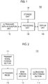
- the ultrasound system 100 includes an ultrasound data acquisition unit 110, a processing unit 120, a storage unit 130 and a display unit 140.
- the ultrasound data acquisition unit 110 is configured to transmit ultrasound beams to a target object and receive ultrasound echoes reflected from the target object to thereby form ultrasound data representative of the target object. An operation of the ultrasound acquisition unit will be described in detail by referring to FIG. 2 .
- FIG. 2 is a block diagram showing an illustrative embodiment of the ultrasound data acquisition unit 120.
- the ultrasound data acquisition unit 110 includes a transmit (Tx) signal forming section 111.
- the Tx signal forming section 121 generates a plurality of Tx signals and apply delays to the Tx signals.
- the delays of the Tx signals is controlled according to a steering angle of scan lines.
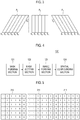
- the Tx signals includes first Tx signals for obtaining a first frame P 1 in which scan lines S 1 -S 6 are not steered, second Tx signals for obtaining a second frame P 2 in which scan lines S 1 -S 6 are steered at a first steering angle of ⁇ 1 and third Tx signals for obtaining a third frame P 3 in which scan lines S 1 -S 6 are steered at a second steering angle of ⁇ 2 , as shown in FIG. 3 .
- the ultrasound data acquisition unit 110 further includes an ultrasound probe 112, which is coupled to the Tx signal forming section 111.
- the ultrasound probe 112 includes an array transducer containing a plurality of transducer elements for reciprocal conversion between electric signals and ultrasound signals.
- the ultrasound probe 112 is configured to transmit ultrasound signals in response to the Tx signals.
- the ultrasound probe 112 is further configured to receive ultrasound echoes reflected from the target object to thereby output receive signals.
- the receive signals includes first receive signals obtained in response to the first Tx signals, second receive signals obtained in response to the second Tx signals and third receive signals obtained in response to the third Tx signals.
- the ultrasound data acquisition unit 110 further includes a beam forming section 113, which is coupled to the ultrasound probe 112.
- the beam forming section 113 is configured to digitize the electrical receive signals to obtain digital signals.
- the beam forming section 113 also applies delays to the digital signals in consideration of distances between the elements of the ultrasound probe 112 and focal points.
- the beam forming section 113 further sums the delayed digital signals to form receive-focused beams.
- the beam forming section 113 forms a first receive-focused beam based on the first receive signals, a second receive-focused beam based on the second receive signals and a third receive-focused beam based on the third receive signals.
- the ultrasound data acquisition unit 110 further includes an ultrasound data forming section 114, which is coupled to the beam forming section 113.
- the ultrasound data forming section 114 is configured to form ultrasound data corresponding to a plurality of frames based on the receive-focused beams.
- the ultrasound data are stored in the storage unit 130.
- the ultrasound data forming section 114 is configured to form a first ultrasound frame data set corresponding to the respective scan lines S 1 -S 6 of the first frame P 1 based on the first receive-focused beams.
- the ultrasound data forming section 114 is configured to form a second ultrasound frame data set corresponding to the respective scan lines S 1 -S 6 of the second frame P 2 based on the second receive-focused beams.
- the ultrasound data forming section 114 is configured to form a third ultrasound frame data set corresponding to the respective scan lines S 1 -S 6 of the third frame P 3 based on the first receive-focused beams.
- the ultrasound data forming section 114 is configured to perform a variety of signal processing (e.g., gain adjustment, etc.), which is necessary for forming the ultrasound data, upon the receive-focused beams.
- the processing unit 120 which is coupled to the ultrasound data acquisition unit 110, is configured to form ultrasound images and mask images corresponding to the frames of the plurality of steering angles based on the plurality of ultrasound frame data sets.
- the mask images are formed to remove seam artifacts appearing in a spatial compound image of the ultrasound images.
- the processing unit 120 is configured to spatially compound a plurality ultrasound images by using the mask images to from an ultrasound spatial compound image. An operation of the processing unit 120 will be described in detail by referring to FIG. 4.
- FIG. 4 is a block diagram showing an illustrative embodiment of the processing unit 120.
- the processing unit 120 includes a mask forming section 121, a mask setting section 122, an image forming section 123 and a spatial compounding section 124.
- the mask forming section 121 is configured to a plurality of masks corresponding to a plurality of frames, respectively, based on the plurality of ultrasound frame data sets. Each of the masks has a size and a pixel number identical to those of each of the frames.
- the mask forming section 121 is configured to a first mask 211 corresponding to the first frame P 1 based on the first ultrasound frame data set as shown in FIG. 5 .
- the mask forming section 121 is configured to a second mask 212 corresponding to the first frame P 2 based on the second ultrasound frame data set.
- the mask forming section 121 is configured to a third mask 213 corresponding to the first frame P 3 based on the third ultrasound frame data set.
- the mask setting section 122 which is coupled to the mask forming section 121, is configured to determine a pixel value corresponding to each of pixels in each of the masks by using the ultrasound frame data sets. More particularly, the mask setting section 122 is configured to detect an intensity of the ultrasound frame data corresponding to the scan line S i at each of the frame by using the ultrasound frame data sets. The mask setting section 122 is further configured to compare the detected intensity with a predetermined threshold. If the intensity is equal to or greater than the predetermined threshold, then it is determined that the ultrasound probe 122 is properly contacted with the surface of the target object. This is so that the mask setting section 122 may assign a value of 1 to pixels corresponding to the scan line S i .
- the mask setting section 122 may assign a value of 0 to pixels corresponding to the scan line S i .
- the mask setting section 122 is configured to detect intensities of the ultrasound frame data corresponding to each of the scan lines S 1 -S 6 of the first frame P 1 and compare the intensities with the predetermined threshold to thereby assign a value of 1 to pixels corresponding to the scan line S 1 -S 6 , which have the intensities equal to or greater than the predetermined threshold value, as shown in FIG. 5 .
- the mask setting section 122 is configured to detect intensities of the ultrasound frame data corresponding to each of the scan lines S 1 -S 6 of the second frame P 2 and compare the intensities with the predetermined threshold.
- the mask setting section 122 is configured to assign a value of 1 to pixels of the second mask 212 corresponding to the scan line S 1 -S 4 , which have the intensities equal to or greater than the predetermined threshold value, and a value of 0 to pixels of the second mask 212 corresponding to the scan line S 5 -S 6 , which have the intensities less than the predetermined threshold value.
- the mask setting section 122 is configured to detect intensities of the ultrasound frame data corresponding to each of the scan lines S 1 -S 6 of the third frame P 3 and compare the intensities with the predetermined threshold.
- the mask setting section 122 is configured to assign a value of 1 to pixels of the third mask 213 corresponding to the scan line S 2 -S 6 , which have the intensities equal to or greater than the predetermined threshold value, and a value of 0 to pixels of the third mask 213 corresponding to the scan line S 1 , which have the intensities less than the predetermined threshold value.
- the image forming section 123 which is coupled to the mask setting unit 122, is configured to form a plurality of mask images based on the plurality of masks provided from the mask setting unit 122. Also, the image forming section 123 is further configured to form a plurality of ultrasound images corresponding to the plurality of mask images by using the ultrasound frame data sets provided from the ultrasound data acquisition unit 110. In one embodiment, the image forming section 123 is configured to form a first mask image 311, a second mask image 312 and a third mask image 313 by using the first mask 211, the second mask 212 and the third mask 213, as shown in FIG. 6 . Further, the image forming section 123 is configured to form first to third ultrasound images 321 to 323 corresponding to the first to third frames P 1 -P 3 by using the first to third ultrasound frame data sets.
- the spatial compounding section 124 is configured to form an ultrasound spatial compound image by compounding the plurality of ultrasound images by using the plurality of mask images.
- the spatial compounding section 124 is configured to sum values of pixels identically positioned in the plurality of ultrasound images to obtain first summation values, and sum values of pixels identically positioned in the plurality of mask images to obtain second summation values.
- the spatial compound section 124 is configured to determine pixel values of the ultrasound spatial compound image.
- the spatial compound image 124 is configured to sum a pixel value of a pixel P 1,1 of the first ultrasound image 321, a pixel value of a pixel S 1,1 of the second ultrasound image 322 and a pixel value of a pixel U 1,1 of the third ultrasound image 323, with respect to a pixel C 1,1 of a ultrasound spatial compound image 330, thereby obtaining a first summation value.
- the spatial compound image 124 is further configured to sum a pixel value of 1 of the first mask image 311, which corresponds to the pixel P 1,1 of the first ultrasound image 321, a pixel value of 1 of the second mask image 312, which corresponds to the pixel S 1,1 of the second ultrasound image, and a pixel value of 0 of the third mask image 313, which corresponds to the pixel U 1,1 of the third ultrasound image, thereby obtaining a second summation value of 2.
- the spatial compounding section 124 is further configured to divide the first summation value by the second summation value (i.e., first summation value/second summation value) to thereby determine a pixel value of a pixel C 1,1 of the ultrasound spatial compound image 330. In the same manner, the spatial compounding section 124 is configured to determine pixel values of pixels C1,2 and C 1,3 of the ultrasound spatial compound image 330.
- the spatial compounding section 124 is configured to sum a pixel value of a pixel P 1,4 of the first ultrasound image 321 and a pixel value of a pixel S 2,4 of the second ultrasound image 322, thereby obtaining a first summation value.
- the spatial compound image 124 is further configured to sum a pixel value of 1 of the first mask image 311, which corresponds to the pixel P 1,4 of the first ultrasound image 321, and a pixel value of 1 of the second mask image 312, which corresponds to the pixel S 2,4 of the second ultrasound image, thereby obtaining a second summation value of 2.
- the spatial compounding section 124 is further configured to divide the first summation value by the second summation value (i.e., first summation value/second summation value) to thereby determine a pixel value of a pixel C 1,4 of the ultrasound spatial compound image 330.
- the spatial compounding section 124 is configured to determine pixel values of pixels C 1,5 and C 1,6 of the ultrasound spatial compound image 330.
- the spatial compound image 124 is configured to sum a pixel value of a pixel P 2,1 of the first ultrasound image 321, a pixel value of a pixel S2,1 of the second ultrasound image 322 and a pixel value of a pixel U 2,1 of the third ultrasound image 323, thereby obtaining a first summation value.
- the spatial compound image 124 is further configured to sum a pixel value of 1 of the first mask image 311, which corresponds to the pixel P 2,1 of the first ultrasound image 321, a pixel value of 1 of the second mask image 312, which corresponds to the pixel S 2,1 of the second ultrasound image, and a pixel value of 1 of the third mask image 313, which corresponds to the pixel U 2,1 of the third ultrasound image, thereby obtaining a second summation value of 3.
- the spatial compounding section 124 is further configured to divide the first summation value by the second summation value (i.e., first summation value/second summation value) to thereby determine a pixel value of a pixel C 2,1 of the ultrasound spatial compound image 330.
- the spatial compounding section 124 is configured to determine pixel values of pixels C 2,2 , C 2,3 , C 2,4 , C 2,5 , C 2,6 , C 3,1 , C 3,2 , C 3,3 , C 3,4 , C 3,5 , C 3,6 , C 4,1 , C 4,2 , C 4,3 , C 4,4 , C 4,5 , C 4,6 , C 5,1 , C 5,2 , C 5,3 , C 5,4 , C 5,5 , C 5,6 , C 6,1 , C 6,2 and C 6,3 of the ultrasound spatial compound image 330.
- the spatial compounding section 124 is configured to sum a pixel value of a pixel P 6,4 of the first ultrasound image 321 and a pixel value of a pixel U 5,4 of the second ultrasound image 323, thereby obtaining a first summation value.
- the spatial compound image 124 is further configured to sum a pixel value of 1 of the first mask image 311, which corresponds to the pixel P 6,4 of the first ultrasound image 321, and a pixel value of 1 of the third mask image 313, which corresponds to the pixel U 5,4 of the third ultrasound image, thereby obtaining a second summation value of 2.
- the spatial compounding section 124 is further configured to divide the first summation value by the second summation value (i.e., first summation value/second summation value) to thereby determine a pixel value of a pixel C 6,4 of the ultrasound spatial compound image 330.
- the spatial compounding section 124 is configured to determine pixel values of pixels C 6,5 and C 6,6 of the ultrasound spatial compound image 330.
- the storage unit 130 which is coupled to the processing unit 120, is configured to store the ultrasound data sets, which have been acquired in the ultrasound data acquisition unit 110.
- the storage unit 130 further stores the plurality of ultrasound images, which have been formed in the processing unit 120.
- the display unit 140 displays the ultrasound spatial compound image.
- a computer-readable storage medium storing instructions that, when executed by a computer, cause the computer to provide a method of spatially compounding ultrasound images based on a plurality of ultrasound frame data sets acquired from a target object and at different steering angles of scan lines in an ultrasound system, the method comprising: setting a plurality of masks corresponding to the respective frames based on the plurality of ultrasound frame date sets for removing seam artifact to form a plurality of mask images corresponding to the respective frames; forming a plurality of ultrasound images corresponding to the plurality of frames based on the plurality of frame data sets; and spatially compounding the plurality of ultrasound image based on the plurality of mask images to form an ultrasound spatial compound image.
Description
- The present application claims priority from Korean Patent Application No.
10-2010-0006412 filed on January 25, 2010 - The present disclosure generally relates to ultrasound image processing, and more particularly to enhancing ultrasound images without lowering a frame rate in an ultrasound system.
- An ultrasound system has been extensively used in the medical field due to its non-invasive and non-destructive nature. Modern high-performance ultrasound imaging diagnostic systems and techniques are commonly used to produce two-dimensional or three-dimensional ultrasound images of internal features of patients.
- Recently, spatial compounding has been adopted in the ultrasound system to provide enhanced ultrasound images. The spatial compounding is implemented by compounding a plurality of ultrasound images (e.g., three ultrasound images), which have been successively formed at different steering angles of scan lines, to form a compound image. In such a case, when the ultrasound images are acquired under the condition that a surface of an ultrasound probe is not properly contacted with a surface of a target object, border lines of the ultrasound images may appear in a compound image formed by spatial compounding of the ultrasound images, i.e., seam artifact occurs in the compound image, which may degrade the compound image.
- An ultrasound system according to the preamble of
claim 1 and a method of forming an ultrasound spatial compound image in this ultrasound system is known from XP031336625 "Suppression of Gradient Across Seam Line Using a Smoothing Filter in Spatially Compounded Ultrasonic Diagnostic Images" by Myoung Hwan Choi. - Embodiments for spatially compounding ultrasound images for removing seam artifact in an ultrasound system are disclosed herein. In one embodiment, by way of nonlimiting example, an ultrasound system comprises the features according to
claim 1. - In another embodiment, a method of forming an ultrasound spatial compound image in an ultrasound system, comprises the features according to claim 4.
- Furthermore, the invention relates to a computer-readable storage medium according to claim 7.
- The Summary is provided to introduce a selection of concepts in a simplified form that are further described below in the Detailed Description. This Summary is not intended to identify key or essential features of the claimed subject matter, nor is it intended to be used in determining the scope of the claimed subject matter.
-
- FIG. 1
- is a block diagram showing an illustrative embodiment of an ultrasound system.
- FIG. 2
- is a block diagram showing an illustrative embodiment of an ultrasound data acquisition unit of
FIG. 1 . - FIG. 3
- is a schematic diagram showing examples of frames consisting of a scan line group with its scan lines not being steered and scan line groups with their scan lines being steered at predetermined steering angles θ1 and θ2. lines being steered at predetermined steering angles θ1 and θ2.
- FIG. 4
- is a block diagram showing an illustrative embodiment of a processing unit of
FIG. 1 . - FIG. 5
- is a schematic diagram showing examples of masks.
- FIG. 6
- is a schematic diagram showing examples of mask images, ultrasound image and a compound image.
- A detailed description may be provided with reference to the accompanying drawings. One of ordinary skill in the art may realize that the following description is illustrative only and is not in any way limiting. Other embodiments of the present invention may readily suggest themselves to such skilled persons having the benefit of this disclosure. Referring to
FIG. 1 , an ultrasound system constructed in accordance with one embodiment is shown. Theultrasound system 100 includes an ultrasounddata acquisition unit 110, aprocessing unit 120, astorage unit 130 and adisplay unit 140. The ultrasounddata acquisition unit 110 is configured to transmit ultrasound beams to a target object and receive ultrasound echoes reflected from the target object to thereby form ultrasound data representative of the target object. An operation of the ultrasound acquisition unit will be described in detail by referring toFIG. 2 . -
FIG. 2 is a block diagram showing an illustrative embodiment of the ultrasounddata acquisition unit 120. Referring toFIG. 2 , the ultrasounddata acquisition unit 110 includes a transmit (Tx)signal forming section 111. The Txsignal forming section 121 generates a plurality of Tx signals and apply delays to the Tx signals. The delays of the Tx signals is controlled according to a steering angle of scan lines. For example, the Tx signals includes first Tx signals for obtaining a first frame P1 in which scan lines S1-S6 are not steered, second Tx signals for obtaining a second frame P2 in which scan lines S1-S6 are steered at a first steering angle of θ1 and third Tx signals for obtaining a third frame P3 in which scan lines S1-S6 are steered at a second steering angle of θ2, as shown inFIG. 3 . - The ultrasound
data acquisition unit 110 further includes anultrasound probe 112, which is coupled to the Txsignal forming section 111. Theultrasound probe 112 includes an array transducer containing a plurality of transducer elements for reciprocal conversion between electric signals and ultrasound signals. Theultrasound probe 112 is configured to transmit ultrasound signals in response to the Tx signals. Theultrasound probe 112 is further configured to receive ultrasound echoes reflected from the target object to thereby output receive signals. In one embodiment, the receive signals includes first receive signals obtained in response to the first Tx signals, second receive signals obtained in response to the second Tx signals and third receive signals obtained in response to the third Tx signals. - The ultrasound
data acquisition unit 110 further includes abeam forming section 113, which is coupled to theultrasound probe 112. Thebeam forming section 113 is configured to digitize the electrical receive signals to obtain digital signals. Thebeam forming section 113 also applies delays to the digital signals in consideration of distances between the elements of theultrasound probe 112 and focal points. Thebeam forming section 113 further sums the delayed digital signals to form receive-focused beams. In one embodiment, thebeam forming section 113 forms a first receive-focused beam based on the first receive signals, a second receive-focused beam based on the second receive signals and a third receive-focused beam based on the third receive signals. - The ultrasound
data acquisition unit 110 further includes an ultrasounddata forming section 114, which is coupled to thebeam forming section 113. The ultrasounddata forming section 114 is configured to form ultrasound data corresponding to a plurality of frames based on the receive-focused beams. The ultrasound data are stored in thestorage unit 130. In one embodiment, the ultrasounddata forming section 114 is configured to form a first ultrasound frame data set corresponding to the respective scan lines S1-S6 of the first frame P1 based on the first receive-focused beams. The ultrasounddata forming section 114 is configured to form a second ultrasound frame data set corresponding to the respective scan lines S1-S6 of the second frame P2 based on the second receive-focused beams. Further, the ultrasounddata forming section 114 is configured to form a third ultrasound frame data set corresponding to the respective scan lines S1-S6 of the third frame P3 based on the first receive-focused beams. The ultrasounddata forming section 114 is configured to perform a variety of signal processing (e.g., gain adjustment, etc.), which is necessary for forming the ultrasound data, upon the receive-focused beams. - Referring back to
FIG. 1 , theprocessing unit 120, which is coupled to the ultrasounddata acquisition unit 110, is configured to form ultrasound images and mask images corresponding to the frames of the plurality of steering angles based on the plurality of ultrasound frame data sets. In this case, the mask images are formed to remove seam artifacts appearing in a spatial compound image of the ultrasound images. Further, theprocessing unit 120 is configured to spatially compound a plurality ultrasound images by using the mask images to from an ultrasound spatial compound image. An operation of theprocessing unit 120 will be described in detail by referring toFIG. 4. FIG. 4 is a block diagram showing an illustrative embodiment of theprocessing unit 120. In one embodiment, theprocessing unit 120 includes amask forming section 121, amask setting section 122, animage forming section 123 and aspatial compounding section 124. - The
mask forming section 121 is configured to a plurality of masks corresponding to a plurality of frames, respectively, based on the plurality of ultrasound frame data sets. Each of the masks has a size and a pixel number identical to those of each of the frames. In one embodiment, themask forming section 121 is configured to afirst mask 211 corresponding to the first frame P1 based on the first ultrasound frame data set as shown inFIG. 5 . Themask forming section 121 is configured to asecond mask 212 corresponding to the first frame P2 based on the second ultrasound frame data set. Further, themask forming section 121 is configured to athird mask 213 corresponding to the first frame P3 based on the third ultrasound frame data set. - The
mask setting section 122, which is coupled to themask forming section 121, is configured to determine a pixel value corresponding to each of pixels in each of the masks by using the ultrasound frame data sets. More particularly, themask setting section 122 is configured to detect an intensity of the ultrasound frame data corresponding to the scan line Si at each of the frame by using the ultrasound frame data sets. Themask setting section 122 is further configured to compare the detected intensity with a predetermined threshold. If the intensity is equal to or greater than the predetermined threshold, then it is determined that theultrasound probe 122 is properly contacted with the surface of the target object. This is so that themask setting section 122 may assign a value of 1 to pixels corresponding to the scan line Si. - On the other hand, if the intensity is less than the predetermined threshold, then it is determined that the
ultrasound 122 is properly contracted with the surface of the target object. This is so that themask setting section 122 may assign a value of 0 to pixels corresponding to the scan line Si. For example, themask setting section 122 is configured to detect intensities of the ultrasound frame data corresponding to each of the scan lines S1-S6 of the first frame P1 and compare the intensities with the predetermined threshold to thereby assign a value of 1 to pixels corresponding to the scan line S1-S6, which have the intensities equal to or greater than the predetermined threshold value, as shown inFIG. 5 . Themask setting section 122 is configured to detect intensities of the ultrasound frame data corresponding to each of the scan lines S1-S6 of the second frame P2 and compare the intensities with the predetermined threshold. Themask setting section 122 is configured to assign a value of 1 to pixels of thesecond mask 212 corresponding to the scan line S1-S4, which have the intensities equal to or greater than the predetermined threshold value, and a value of 0 to pixels of thesecond mask 212 corresponding to the scan line S5-S6, which have the intensities less than the predetermined threshold value. Themask setting section 122 is configured to detect intensities of the ultrasound frame data corresponding to each of the scan lines S1-S6 of the third frame P3 and compare the intensities with the predetermined threshold. Themask setting section 122 is configured to assign a value of 1 to pixels of thethird mask 213 corresponding to the scan line S2-S6, which have the intensities equal to or greater than the predetermined threshold value, and a value of 0 to pixels of thethird mask 213 corresponding to the scan line S1, which have the intensities less than the predetermined threshold value. - The
image forming section 123, which is coupled to themask setting unit 122, is configured to form a plurality of mask images based on the plurality of masks provided from themask setting unit 122. Also, theimage forming section 123 is further configured to form a plurality of ultrasound images corresponding to the plurality of mask images by using the ultrasound frame data sets provided from the ultrasounddata acquisition unit 110. In one embodiment, theimage forming section 123 is configured to form afirst mask image 311, a second mask image 312 and athird mask image 313 by using thefirst mask 211, thesecond mask 212 and thethird mask 213, as shown inFIG. 6 . Further, theimage forming section 123 is configured to form first tothird ultrasound images 321 to 323 corresponding to the first to third frames P1-P3 by using the first to third ultrasound frame data sets. - The
spatial compounding section 124 is configured to form an ultrasound spatial compound image by compounding the plurality of ultrasound images by using the plurality of mask images. Thespatial compounding section 124 is configured to sum values of pixels identically positioned in the plurality of ultrasound images to obtain first summation values, and sum values of pixels identically positioned in the plurality of mask images to obtain second summation values. Thespatial compound section 124 is configured to determine pixel values of the ultrasound spatial compound image. In one embodiment, thespatial compound image 124 is configured to sum a pixel value of a pixel P1,1 of thefirst ultrasound image 321, a pixel value of a pixel S1,1 of thesecond ultrasound image 322 and a pixel value of a pixel U1,1 of thethird ultrasound image 323, with respect to a pixel C1,1 of a ultrasoundspatial compound image 330, thereby obtaining a first summation value. Thespatial compound image 124 is further configured to sum a pixel value of 1 of thefirst mask image 311, which corresponds to the pixel P1,1 of thefirst ultrasound image 321, a pixel value of 1 of the second mask image 312, which corresponds to the pixel S1,1 of the second ultrasound image, and a pixel value of 0 of thethird mask image 313, which corresponds to the pixel U1,1 of the third ultrasound image, thereby obtaining a second summation value of 2. Thespatial compounding section 124 is further configured to divide the first summation value by the second summation value (i.e., first summation value/second summation value) to thereby determine a pixel value of a pixel C1,1 of the ultrasoundspatial compound image 330. In the same manner, thespatial compounding section 124 is configured to determine pixel values of pixels C1,2 and C1,3 of the ultrasoundspatial compound image 330. - With respect to a pixel C1,4 of the ultrasound
spatial compound image 330, thespatial compounding section 124 is configured to sum a pixel value of a pixel P1,4 of thefirst ultrasound image 321 and a pixel value of a pixel S2,4 of thesecond ultrasound image 322, thereby obtaining a first summation value. Thespatial compound image 124 is further configured to sum a pixel value of 1 of thefirst mask image 311, which corresponds to the pixel P1,4 of thefirst ultrasound image 321, and a pixel value of 1 of the second mask image 312, which corresponds to the pixel S2,4 of the second ultrasound image, thereby obtaining a second summation value of 2. Thespatial compounding section 124 is further configured to divide the first summation value by the second summation value (i.e., first summation value/second summation value) to thereby determine a pixel value of a pixel C1,4 of the ultrasoundspatial compound image 330. In the same manner, thespatial compounding section 124 is configured to determine pixel values of pixels C1,5 and C1,6 of the ultrasoundspatial compound image 330. - With respect to a pixel C2,1 of the ultrasound
spatial compound image 330, thespatial compound image 124 is configured to sum a pixel value of a pixel P2,1 of thefirst ultrasound image 321, a pixel value of a pixel S2,1 of thesecond ultrasound image 322 and a pixel value of a pixel U2,1 of thethird ultrasound image 323, thereby obtaining a first summation value. Thespatial compound image 124 is further configured to sum a pixel value of 1 of thefirst mask image 311, which corresponds to the pixel P2,1 of thefirst ultrasound image 321, a pixel value of 1 of the second mask image 312, which corresponds to the pixel S2,1 of the second ultrasound image, and a pixel value of 1 of thethird mask image 313, which corresponds to the pixel U2,1 of the third ultrasound image, thereby obtaining a second summation value of 3. Thespatial compounding section 124 is further configured to divide the first summation value by the second summation value (i.e., first summation value/second summation value) to thereby determine a pixel value of a pixel C2,1 of the ultrasoundspatial compound image 330. In the same manner, thespatial compounding section 124 is configured to determine pixel values of pixels C2,2, C2,3, C2,4, C2,5, C2,6, C3,1, C3,2, C3,3, C3,4, C3,5, C3,6, C4,1, C4,2, C4,3, C4,4, C4,5, C4,6, C5,1, C5,2, C5,3, C5,4, C5,5, C5,6, C6,1, C6,2 and C6,3 of the ultrasoundspatial compound image 330. - With respect to a pixel C6,4 of the ultrasound
spatial compound image 330, thespatial compounding section 124 is configured to sum a pixel value of a pixel P6,4 of thefirst ultrasound image 321 and a pixel value of a pixel U5,4 of thesecond ultrasound image 323, thereby obtaining a first summation value. Thespatial compound image 124 is further configured to sum a pixel value of 1 of thefirst mask image 311, which corresponds to the pixel P6,4 of thefirst ultrasound image 321, and a pixel value of 1 of thethird mask image 313, which corresponds to the pixel U5,4 of the third ultrasound image, thereby obtaining a second summation value of 2. Thespatial compounding section 124 is further configured to divide the first summation value by the second summation value (i.e., first summation value/second summation value) to thereby determine a pixel value of a pixel C6,4 of the ultrasoundspatial compound image 330. In the same manner, thespatial compounding section 124 is configured to determine pixel values of pixels C6,5 and C6,6 of the ultrasoundspatial compound image 330. Referring back toFIG. 1 , thestorage unit 130, which is coupled to theprocessing unit 120, is configured to store the ultrasound data sets, which have been acquired in the ultrasounddata acquisition unit 110. Thestorage unit 130 further stores the plurality of ultrasound images, which have been formed in theprocessing unit 120. Thedisplay unit 140 displays the ultrasound spatial compound image. - In another embodiment, there is provided a computer-readable storage medium storing instructions that, when executed by a computer, cause the computer to provide a method of spatially compounding ultrasound images based on a plurality of ultrasound frame data sets acquired from a target object and at different steering angles of scan lines in an ultrasound system, the method comprising: setting a plurality of masks corresponding to the respective frames based on the plurality of ultrasound frame date sets for removing seam artifact to form a plurality of mask images corresponding to the respective frames; forming a plurality of ultrasound images corresponding to the plurality of frames based on the plurality of frame data sets; and spatially compounding the plurality of ultrasound image based on the plurality of mask images to form an ultrasound spatial compound image.
- Although embodiments have been described with reference to a number of illustrative embodiments thereof, it should be understood that numerous other modifications and embodiments can be devised by those skilled in the art. More particularly, numerous variations and modifications are possible in the component parts and/or arrangements of the subject combination arrangement within the scope of the disclosure, the drawings and the appended claims. In addition to variations and modifications in the component parts and/or arrangements, alternative uses will also be apparent to those skilled in the art.
Claims (7)
- An ultrasound system (100), comprising:an ultrasound data acquisition unit (110) configured to transmit ultrasound beams to a target object, receive ultrasound echoes reflected from the target object and provide a plurality of ultrasound frame data sets for a plurality of frames, said plurality of ultrasound frame data being acquired at different steering angles of scan lines; anda processing unit (120) configured to form a plurality of ultrasound images,wherein the processing unit (120) includes:a mask forming section configured to form masks corresponding to the respective frames based on the ultrasound frame data sets,a mask setting section configured to determine pixel values of pixels of each of the mask based on intensities of the ultrasound frame data sets,an image forming section configured to form a plurality of mask images based on the masks and the plurality of ultrasound images based on the ultrasound frame data sets, anda spatially compounding section configured to spatially compound the plurality of ultrasound image based on the plurality of mask images to form an ultrasound spatial compound image,wherein the spatial compounding section is configured to sum pixel values of pixels overlapped at the ultrasound images to obtain a first summation value, sum pixel values of pixels overlapped at the mask images to obtain a second summation value and divide the first summation value by the second summation value to determine a pixel value at a corresponding pixel of the ultrasound spatial compound image.
- The ultrasound system (100) of Claim 1, wherein the mask images have identical sizes and pixel numbers to those of the corresponding ultrasound images.
- The ultrasound system (100) of Claim 1, wherein the mask setting section is configured to detect an intensity of each of the frames corresponding to the respective scan lines by using the ultrasound frame data sets, compare the detected intensity with a predetermined threshold, assign, when the intensity is equal to or greater than a predetermined threshold, a value of 1 to pixels corresponding to the scan line, and assign, when the intensity is less than the predetermined threshold, a value of 0 to pixels corresponding to the scan line.
- A method of forming an ultrasound spatial compound image in an ultrasound system (100), comprising:a) transmitting ultrasound beams to a target object, receiving ultrasound echoes reflected from the target object and providing a plurality of ultrasound frame data sets for a plurality of frames, said plurality of ultrasound frame data being acquired at different steering angles of scan lines;b) forming masks corresponding to the respective frames based on the ultrasound frame data sets;c) determining pixel values of pixels of each of the mask based on intensities of the ultrasound frame date sets for removing seam artifact to form a plurality of mask images corresponding to the respective frames;d) forming a plurality of ultrasound images corresponding to the plurality of frames based on the plurality of frame data sets; ande) spatially compounding the plurality of ultrasound image based on the plurality of mask images to form an ultrasound spatial compound image,wherein the e) includes:summing pixel values of pixels overlapped at the ultrasound images to obtain a first summation value;summing pixel values of pixels overlapped at the mask images to obtain a second summation value; anddividing the first summation value by the second summation value to determine a pixel value at a corresponding pixel of the ultrasound spatial compound image.
- The method of Claim 4, wherein the masks have identical sizes and pixel numbers to those of the corresponding ultrasound images.
- The method of Claim 4, wherein the c) includes:detecting an intensity of each of the frames corresponding to the respective scan lines by using the ultrasound frame data sets;comparing the detected intensity with a predetermined threshold,assigning, when the intensity is equal to or greater than a predetermined threshold, a value of 1 to pixels corresponding to the scan line; andassigning, when the intensity is less than the predetermined threshold, a value of 0 to pixels corresponding to the scan line.
- A computer-readable storage medium storing instructions that, when executed by a computer, cause the computer to provide a method of spatially compounding ultrasound images based on a plurality of ultrasound frame data sets acquired from a target object and at different steering angles of scan lines in an ultrasound system (100), the method comprising:forming masks corresponding to the respective frames based on the ultrasound frame data sets;determining pixel values of pixels of each of the mask based on intensities of the ultrasound frame date sets for removing seam artifact to form a plurality of mask images corresponding to the respective frames;forming a plurality of ultrasound images corresponding to the plurality of frames based on the plurality of frame data sets; andspatially compounding the plurality of ultrasound image based on the plurality of mask images to form an ultrasound spatial compound image,wherein the determining pixel values of pixels of each of the mask includes:detecting an intensity of each of the frames corresponding to the respective scan lines by using the ultrasound frame data sets;comparing the detected intensity with a predetermined threshold, assigning, when the intensity is equal to or greater than a predetermined threshold, a value of 1 to pixels corresponding to the scan line; andassigning, when the intensity is less than the predetermined threshold, a value of 0 to pixels corresponding to the scan line,wherein the spatially compounding the plurality of ultrasound image includes:summing pixel values of pixels overlapped at the ultrasound images to obtain a first summation value;summing pixel values of pixels overlapped at the mask images to obtain a second summation value; anddividing the first summation value by the second summation value to determine a pixel value at a corresponding pixel of the ultrasound spatial compound image.
Applications Claiming Priority (1)
| Application Number | Priority Date | Filing Date | Title |
|---|---|---|---|
| KR1020100006412A KR101183003B1 (en) | 2010-01-25 | 2010-01-25 | Ultrasound system and method for providing ultrasound spatial compound image based on masks |
Publications (2)
| Publication Number | Publication Date |
|---|---|
| EP2347713A1 EP2347713A1 (en) | 2011-07-27 |
| EP2347713B1 true EP2347713B1 (en) | 2021-03-03 |
Family
ID=43981727
Family Applications (1)
| Application Number | Title | Priority Date | Filing Date |
|---|---|---|---|
| EP11151475.8A Active EP2347713B1 (en) | 2010-01-25 | 2011-01-20 | Ultrasound image enhancement in an ultrasound system |
Country Status (4)
| Country | Link |
|---|---|
| US (1) | US20110184292A1 (en) |
| EP (1) | EP2347713B1 (en) |
| JP (1) | JP5756639B2 (en) |
| KR (1) | KR101183003B1 (en) |
Families Citing this family (5)
| Publication number | Priority date | Publication date | Assignee | Title |
|---|---|---|---|---|
| JP5272084B2 (en) * | 2012-01-11 | 2013-08-28 | 日立アロカメディカル株式会社 | Ultrasonic diagnostic equipment |
| CN102551809A (en) * | 2012-02-29 | 2012-07-11 | 飞依诺科技(苏州)有限公司 | Graphic extension imaging method in ultrasonic diagnosis |
| KR101956308B1 (en) * | 2016-11-04 | 2019-03-08 | 서강대학교산학협력단 | System for removing background noise of photo acoustic imaging |
| US11439369B1 (en) | 2017-10-26 | 2022-09-13 | United States Of America As Represented By The Secretary Of The Air Force | Method and apparatus for imaging with reduced level of off-axis artifacts |
| KR102655278B1 (en) * | 2018-07-24 | 2024-04-08 | 삼성메디슨 주식회사 | Ultrasound diagnostic apparatus and method for operating the same |
Citations (1)
| Publication number | Priority date | Publication date | Assignee | Title |
|---|---|---|---|---|
| US6181810B1 (en) * | 1998-07-30 | 2001-01-30 | Scimed Life Systems, Inc. | Method and apparatus for spatial and temporal filtering of intravascular ultrasonic image data |
Family Cites Families (9)
| Publication number | Priority date | Publication date | Assignee | Title |
|---|---|---|---|---|
| US5821915A (en) * | 1995-10-11 | 1998-10-13 | Hewlett-Packard Company | Method and apparatus for removing artifacts from scanned halftone images |
| US6224552B1 (en) * | 1998-10-01 | 2001-05-01 | Atl Ultrasound | Ultrasonic diagnostic imaging system with reduced spatial compounding seam artifacts |
| US6364835B1 (en) * | 1998-11-20 | 2002-04-02 | Acuson Corporation | Medical diagnostic ultrasound imaging methods for extended field of view |
| US6895077B2 (en) * | 2001-11-21 | 2005-05-17 | University Of Massachusetts Medical Center | System and method for x-ray fluoroscopic imaging |
| US20040077946A1 (en) * | 2002-10-15 | 2004-04-22 | Jun Ohmiya | Image processing apparatus, method and program |
| US6858010B2 (en) * | 2003-05-06 | 2005-02-22 | Siemens Medical Solutions Usa, Inc. | Identifying clinical markers in spatial compounding ultrasound imaging |
| JP4095494B2 (en) * | 2003-05-30 | 2008-06-04 | キヤノン株式会社 | Ophthalmic image processing apparatus and processing method |
| US20050124886A1 (en) * | 2003-11-21 | 2005-06-09 | Koninklijke Philips Electronics N.V. | System and method for generating ultrasound images having variable spatial compounding |
| US7780601B2 (en) * | 2007-06-05 | 2010-08-24 | Siemens Medical Solutions Usa, Inc. | Adaptive clinical marker preservation in spatial compound ultrasound imaging |
-
2010
- 2010-01-25 KR KR1020100006412A patent/KR101183003B1/en active IP Right Grant
-
2011
- 2011-01-20 EP EP11151475.8A patent/EP2347713B1/en active Active
- 2011-01-21 US US13/011,470 patent/US20110184292A1/en not_active Abandoned
- 2011-01-24 JP JP2011012246A patent/JP5756639B2/en not_active Expired - Fee Related
Patent Citations (1)
| Publication number | Priority date | Publication date | Assignee | Title |
|---|---|---|---|---|
| US6181810B1 (en) * | 1998-07-30 | 2001-01-30 | Scimed Life Systems, Inc. | Method and apparatus for spatial and temporal filtering of intravascular ultrasonic image data |
Also Published As
| Publication number | Publication date |
|---|---|
| KR101183003B1 (en) | 2012-09-18 |
| KR20110086989A (en) | 2011-08-02 |
| EP2347713A1 (en) | 2011-07-27 |
| US20110184292A1 (en) | 2011-07-28 |
| JP5756639B2 (en) | 2015-07-29 |
| JP2011152415A (en) | 2011-08-11 |
Similar Documents
| Publication | Publication Date | Title |
|---|---|---|
| US8792690B2 (en) | Enhancing quality of ultrasound spatial compound image based on beam profile in ultrasound system | |
| US8506488B2 (en) | Ultrasound image enhancement in an ultrasound system | |
| US8968199B2 (en) | Spatial compound imaging in an ultrasound system | |
| US9008383B2 (en) | Enhancing quality of ultrasound image in ultrasound system | |
| US20120101378A1 (en) | Providing an ultrasound spatial compound image based on a phased array probe in an ultrasound system | |
| EP2347713B1 (en) | Ultrasound image enhancement in an ultrasound system | |
| US8727990B2 (en) | Providing an ultrasound spatial compound image in an ultrasound system | |
| US9081097B2 (en) | Component frame enhancement for spatial compounding in ultrasound imaging | |
| US20110054324A1 (en) | Ultrasound system and method for providing multiple plane images for a plurality of views | |
| US9151841B2 (en) | Providing an ultrasound spatial compound image based on center lines of ultrasound images in an ultrasound system | |
| US8956298B2 (en) | Providing an ultrasound spatial compound image in an ultrasound system | |
| CN106600550B (en) | Ultrasonic image processing method and system | |
| JP2011083600A (en) | Ultrasonic system and method for detecting object of interest based on luminance value of the object of interest | |
| US8037767B2 (en) | Transmit apodization using a sinc function in an ultrasound system | |
| US20100280383A1 (en) | Color Doppler Mode Image Processing In An Ultrasound System | |
| US20110054323A1 (en) | Ultrasound system and method for providing an ultrasound spatial compound image considering steering angle | |
| US20170168148A1 (en) | Synchronized phased array data acquisition from multiple acoustic windows | |
| EP2422705B1 (en) | Ultrasound strain imaging | |
| WO2015136534A1 (en) | Strong echoes in ultrasound images | |
| US8864668B2 (en) | Formation of an elastic image in an ultrasound system | |
| US8503714B2 (en) | Dropout correction in ultrasound strain imaging | |
| CN113243936A (en) | Ultrasonic wave beam forming method and device, ultrasonic equipment and storage medium | |
| Teixeira Prado et al. | The Use of Instantaneous Phase for Improving Saft Images | |
| KR20150124479A (en) | Module for Processing Ultrasonic Signal Based on Spatial Coherence and Method for Processing Ultrasonic Signal |
Legal Events
| Date | Code | Title | Description |
|---|---|---|---|
| PUAI | Public reference made under article 153(3) epc to a published international application that has entered the european phase |
Free format text: ORIGINAL CODE: 0009012 |
|
| AK | Designated contracting states |
Kind code of ref document: A1 Designated state(s): AL AT BE BG CH CY CZ DE DK EE ES FI FR GB GR HR HU IE IS IT LI LT LU LV MC MK MT NL NO PL PT RO RS SE SI SK SM TR |
|
| AX | Request for extension of the european patent |
Extension state: BA ME |
|
| RIN1 | Information on inventor provided before grant (corrected) |
Inventor name: KIM, JEONG SIK Inventor name: YOO, JAE HEUNG |
|
| RTI1 | Title (correction) |
Free format text: ULTRASOUND IMAGE ENHANCEMENT IN AN ULTRASOUND SYSTEM |
|
| 17P | Request for examination filed |
Effective date: 20120126 |
|
| 17Q | First examination report despatched |
Effective date: 20130530 |
|
| STAA | Information on the status of an ep patent application or granted ep patent |
Free format text: STATUS: EXAMINATION IS IN PROGRESS |
|
| GRAP | Despatch of communication of intention to grant a patent |
Free format text: ORIGINAL CODE: EPIDOSNIGR1 |
|
| STAA | Information on the status of an ep patent application or granted ep patent |
Free format text: STATUS: GRANT OF PATENT IS INTENDED |
|
| INTG | Intention to grant announced |
Effective date: 20200924 |
|
| GRAS | Grant fee paid |
Free format text: ORIGINAL CODE: EPIDOSNIGR3 |
|
| STAA | Information on the status of an ep patent application or granted ep patent |
Free format text: STATUS: GRANT OF PATENT IS INTENDED |
|
| RAP1 | Party data changed (applicant data changed or rights of an application transferred) |
Owner name: SAMSUNG MEDISON CO., LTD. |
|
| GRAA | (expected) grant |
Free format text: ORIGINAL CODE: 0009210 |
|
| STAA | Information on the status of an ep patent application or granted ep patent |
Free format text: STATUS: THE PATENT HAS BEEN GRANTED |
|
| AK | Designated contracting states |
Kind code of ref document: B1 Designated state(s): AL AT BE BG CH CY CZ DE DK EE ES FI FR GB GR HR HU IE IS IT LI LT LU LV MC MK MT NL NO PL PT RO RS SE SI SK SM TR |
|
| REG | Reference to a national code |
Ref country code: GB Ref legal event code: FG4D |
|
| REG | Reference to a national code |
Ref country code: AT Ref legal event code: REF Ref document number: 1366333 Country of ref document: AT Kind code of ref document: T Effective date: 20210315 Ref country code: CH Ref legal event code: EP |
|
| REG | Reference to a national code |
Ref country code: DE Ref legal event code: R096 Ref document number: 602011070278 Country of ref document: DE |
|
| REG | Reference to a national code |
Ref country code: IE Ref legal event code: FG4D |
|
| REG | Reference to a national code |
Ref country code: LT Ref legal event code: MG9D |
|
| PG25 | Lapsed in a contracting state [announced via postgrant information from national office to epo] |
Ref country code: LT Free format text: LAPSE BECAUSE OF FAILURE TO SUBMIT A TRANSLATION OF THE DESCRIPTION OR TO PAY THE FEE WITHIN THE PRESCRIBED TIME-LIMIT Effective date: 20210303 Ref country code: FI Free format text: LAPSE BECAUSE OF FAILURE TO SUBMIT A TRANSLATION OF THE DESCRIPTION OR TO PAY THE FEE WITHIN THE PRESCRIBED TIME-LIMIT Effective date: 20210303 Ref country code: GR Free format text: LAPSE BECAUSE OF FAILURE TO SUBMIT A TRANSLATION OF THE DESCRIPTION OR TO PAY THE FEE WITHIN THE PRESCRIBED TIME-LIMIT Effective date: 20210604 Ref country code: HR Free format text: LAPSE BECAUSE OF FAILURE TO SUBMIT A TRANSLATION OF THE DESCRIPTION OR TO PAY THE FEE WITHIN THE PRESCRIBED TIME-LIMIT Effective date: 20210303 Ref country code: BG Free format text: LAPSE BECAUSE OF FAILURE TO SUBMIT A TRANSLATION OF THE DESCRIPTION OR TO PAY THE FEE WITHIN THE PRESCRIBED TIME-LIMIT Effective date: 20210603 Ref country code: NO Free format text: LAPSE BECAUSE OF FAILURE TO SUBMIT A TRANSLATION OF THE DESCRIPTION OR TO PAY THE FEE WITHIN THE PRESCRIBED TIME-LIMIT Effective date: 20210603 |
|
| REG | Reference to a national code |
Ref country code: NL Ref legal event code: MP Effective date: 20210303 |
|
| REG | Reference to a national code |
Ref country code: AT Ref legal event code: MK05 Ref document number: 1366333 Country of ref document: AT Kind code of ref document: T Effective date: 20210303 |
|
| PG25 | Lapsed in a contracting state [announced via postgrant information from national office to epo] |
Ref country code: SE Free format text: LAPSE BECAUSE OF FAILURE TO SUBMIT A TRANSLATION OF THE DESCRIPTION OR TO PAY THE FEE WITHIN THE PRESCRIBED TIME-LIMIT Effective date: 20210303 Ref country code: LV Free format text: LAPSE BECAUSE OF FAILURE TO SUBMIT A TRANSLATION OF THE DESCRIPTION OR TO PAY THE FEE WITHIN THE PRESCRIBED TIME-LIMIT Effective date: 20210303 Ref country code: RS Free format text: LAPSE BECAUSE OF FAILURE TO SUBMIT A TRANSLATION OF THE DESCRIPTION OR TO PAY THE FEE WITHIN THE PRESCRIBED TIME-LIMIT Effective date: 20210303 Ref country code: PL Free format text: LAPSE BECAUSE OF FAILURE TO SUBMIT A TRANSLATION OF THE DESCRIPTION OR TO PAY THE FEE WITHIN THE PRESCRIBED TIME-LIMIT Effective date: 20210303 |
|
| PG25 | Lapsed in a contracting state [announced via postgrant information from national office to epo] |
Ref country code: NL Free format text: LAPSE BECAUSE OF FAILURE TO SUBMIT A TRANSLATION OF THE DESCRIPTION OR TO PAY THE FEE WITHIN THE PRESCRIBED TIME-LIMIT Effective date: 20210303 |
|
| PG25 | Lapsed in a contracting state [announced via postgrant information from national office to epo] |
Ref country code: AT Free format text: LAPSE BECAUSE OF FAILURE TO SUBMIT A TRANSLATION OF THE DESCRIPTION OR TO PAY THE FEE WITHIN THE PRESCRIBED TIME-LIMIT Effective date: 20210303 Ref country code: SM Free format text: LAPSE BECAUSE OF FAILURE TO SUBMIT A TRANSLATION OF THE DESCRIPTION OR TO PAY THE FEE WITHIN THE PRESCRIBED TIME-LIMIT Effective date: 20210303 Ref country code: CZ Free format text: LAPSE BECAUSE OF FAILURE TO SUBMIT A TRANSLATION OF THE DESCRIPTION OR TO PAY THE FEE WITHIN THE PRESCRIBED TIME-LIMIT Effective date: 20210303 Ref country code: EE Free format text: LAPSE BECAUSE OF FAILURE TO SUBMIT A TRANSLATION OF THE DESCRIPTION OR TO PAY THE FEE WITHIN THE PRESCRIBED TIME-LIMIT Effective date: 20210303 |
|
| PG25 | Lapsed in a contracting state [announced via postgrant information from national office to epo] |
Ref country code: IS Free format text: LAPSE BECAUSE OF FAILURE TO SUBMIT A TRANSLATION OF THE DESCRIPTION OR TO PAY THE FEE WITHIN THE PRESCRIBED TIME-LIMIT Effective date: 20210703 Ref country code: RO Free format text: LAPSE BECAUSE OF FAILURE TO SUBMIT A TRANSLATION OF THE DESCRIPTION OR TO PAY THE FEE WITHIN THE PRESCRIBED TIME-LIMIT Effective date: 20210303 Ref country code: PT Free format text: LAPSE BECAUSE OF FAILURE TO SUBMIT A TRANSLATION OF THE DESCRIPTION OR TO PAY THE FEE WITHIN THE PRESCRIBED TIME-LIMIT Effective date: 20210705 Ref country code: SK Free format text: LAPSE BECAUSE OF FAILURE TO SUBMIT A TRANSLATION OF THE DESCRIPTION OR TO PAY THE FEE WITHIN THE PRESCRIBED TIME-LIMIT Effective date: 20210303 Ref country code: ES Free format text: LAPSE BECAUSE OF FAILURE TO SUBMIT A TRANSLATION OF THE DESCRIPTION OR TO PAY THE FEE WITHIN THE PRESCRIBED TIME-LIMIT Effective date: 20210303 |
|
| REG | Reference to a national code |
Ref country code: DE Ref legal event code: R097 Ref document number: 602011070278 Country of ref document: DE |
|
| PLBE | No opposition filed within time limit |
Free format text: ORIGINAL CODE: 0009261 |
|
| STAA | Information on the status of an ep patent application or granted ep patent |
Free format text: STATUS: NO OPPOSITION FILED WITHIN TIME LIMIT |
|
| PG25 | Lapsed in a contracting state [announced via postgrant information from national office to epo] |
Ref country code: DK Free format text: LAPSE BECAUSE OF FAILURE TO SUBMIT A TRANSLATION OF THE DESCRIPTION OR TO PAY THE FEE WITHIN THE PRESCRIBED TIME-LIMIT Effective date: 20210303 Ref country code: AL Free format text: LAPSE BECAUSE OF FAILURE TO SUBMIT A TRANSLATION OF THE DESCRIPTION OR TO PAY THE FEE WITHIN THE PRESCRIBED TIME-LIMIT Effective date: 20210303 |
|
| 26N | No opposition filed |
Effective date: 20211206 |
|
| PG25 | Lapsed in a contracting state [announced via postgrant information from national office to epo] |
Ref country code: SI Free format text: LAPSE BECAUSE OF FAILURE TO SUBMIT A TRANSLATION OF THE DESCRIPTION OR TO PAY THE FEE WITHIN THE PRESCRIBED TIME-LIMIT Effective date: 20210303 |
|
| PG25 | Lapsed in a contracting state [announced via postgrant information from national office to epo] |
Ref country code: IS Free format text: LAPSE BECAUSE OF FAILURE TO SUBMIT A TRANSLATION OF THE DESCRIPTION OR TO PAY THE FEE WITHIN THE PRESCRIBED TIME-LIMIT Effective date: 20210703 |
|
| PG25 | Lapsed in a contracting state [announced via postgrant information from national office to epo] |
Ref country code: MC Free format text: LAPSE BECAUSE OF FAILURE TO SUBMIT A TRANSLATION OF THE DESCRIPTION OR TO PAY THE FEE WITHIN THE PRESCRIBED TIME-LIMIT Effective date: 20210303 |
|
| REG | Reference to a national code |
Ref country code: CH Ref legal event code: PL |
|
| GBPC | Gb: european patent ceased through non-payment of renewal fee |
Effective date: 20220120 |
|
| REG | Reference to a national code |
Ref country code: BE Ref legal event code: MM Effective date: 20220131 |
|
| PG25 | Lapsed in a contracting state [announced via postgrant information from national office to epo] |
Ref country code: LU Free format text: LAPSE BECAUSE OF NON-PAYMENT OF DUE FEES Effective date: 20220120 Ref country code: GB Free format text: LAPSE BECAUSE OF NON-PAYMENT OF DUE FEES Effective date: 20220120 |
|
| PG25 | Lapsed in a contracting state [announced via postgrant information from national office to epo] |
Ref country code: BE Free format text: LAPSE BECAUSE OF NON-PAYMENT OF DUE FEES Effective date: 20220131 |
|
| PG25 | Lapsed in a contracting state [announced via postgrant information from national office to epo] |
Ref country code: LI Free format text: LAPSE BECAUSE OF NON-PAYMENT OF DUE FEES Effective date: 20220131 Ref country code: CH Free format text: LAPSE BECAUSE OF NON-PAYMENT OF DUE FEES Effective date: 20220131 |
|
| PG25 | Lapsed in a contracting state [announced via postgrant information from national office to epo] |
Ref country code: IE Free format text: LAPSE BECAUSE OF NON-PAYMENT OF DUE FEES Effective date: 20220120 |
|
| PGFP | Annual fee paid to national office [announced via postgrant information from national office to epo] |
Ref country code: IT Payment date: 20221206 Year of fee payment: 13 Ref country code: DE Payment date: 20221205 Year of fee payment: 13 |
|
| PGFP | Annual fee paid to national office [announced via postgrant information from national office to epo] |
Ref country code: FR Payment date: 20231206 Year of fee payment: 14 |
|
| PG25 | Lapsed in a contracting state [announced via postgrant information from national office to epo] |
Ref country code: HU Free format text: LAPSE BECAUSE OF FAILURE TO SUBMIT A TRANSLATION OF THE DESCRIPTION OR TO PAY THE FEE WITHIN THE PRESCRIBED TIME-LIMIT; INVALID AB INITIO Effective date: 20110120 |