US20180098654A1 - Drying clip - Google Patents
Drying clip Download PDFInfo
- Publication number
- US20180098654A1 US20180098654A1 US15/499,772 US201715499772A US2018098654A1 US 20180098654 A1 US20180098654 A1 US 20180098654A1 US 201715499772 A US201715499772 A US 201715499772A US 2018098654 A1 US2018098654 A1 US 2018098654A1
- Authority
- US
- United States
- Prior art keywords
- clip
- grasping portion
- drying
- arm
- drying clip
- Prior art date
- Legal status (The legal status is an assumption and is not a legal conclusion. Google has not performed a legal analysis and makes no representation as to the accuracy of the status listed.)
- Abandoned
Links
Images

Classifications
-
- A—HUMAN NECESSITIES
- A47—FURNITURE; DOMESTIC ARTICLES OR APPLIANCES; COFFEE MILLS; SPICE MILLS; SUCTION CLEANERS IN GENERAL
- A47G—HOUSEHOLD OR TABLE EQUIPMENT
- A47G29/00—Supports, holders, or containers for household use, not provided for in groups A47G1/00-A47G27/00 or A47G33/00
- A47G29/08—Holders for articles of personal use in general, e.g. brushes
-
- A—HUMAN NECESSITIES
- A47—FURNITURE; DOMESTIC ARTICLES OR APPLIANCES; COFFEE MILLS; SPICE MILLS; SUCTION CLEANERS IN GENERAL
- A47L—DOMESTIC WASHING OR CLEANING; SUCTION CLEANERS IN GENERAL
- A47L13/00—Implements for cleaning floors, carpets, furniture, walls, or wall coverings
- A47L13/10—Scrubbing; Scouring; Cleaning; Polishing
- A47L13/50—Auxiliary implements
- A47L13/51—Storing of cleaning tools, e.g. containers therefor
- A47L13/512—Clamping devices for hanging the tools
-
- A—HUMAN NECESSITIES
- A47—FURNITURE; DOMESTIC ARTICLES OR APPLIANCES; COFFEE MILLS; SPICE MILLS; SUCTION CLEANERS IN GENERAL
- A47L—DOMESTIC WASHING OR CLEANING; SUCTION CLEANERS IN GENERAL
- A47L19/00—Drying devices for crockery or table-ware, e.g. tea-cloths
-
- A—HUMAN NECESSITIES
- A47—FURNITURE; DOMESTIC ARTICLES OR APPLIANCES; COFFEE MILLS; SPICE MILLS; SUCTION CLEANERS IN GENERAL
- A47L—DOMESTIC WASHING OR CLEANING; SUCTION CLEANERS IN GENERAL
- A47L23/00—Cleaning footwear
- A47L23/20—Devices or implements for drying footwear, also with heating arrangements
-
- B—PERFORMING OPERATIONS; TRANSPORTING
- B25—HAND TOOLS; PORTABLE POWER-DRIVEN TOOLS; MANIPULATORS
- B25H—WORKSHOP EQUIPMENT, e.g. FOR MARKING-OUT WORK; STORAGE MEANS FOR WORKSHOPS
- B25H3/00—Storage means or arrangements for workshops facilitating access to, or handling of, work tools or instruments
-
- F—MECHANICAL ENGINEERING; LIGHTING; HEATING; WEAPONS; BLASTING
- F16—ENGINEERING ELEMENTS AND UNITS; GENERAL MEASURES FOR PRODUCING AND MAINTAINING EFFECTIVE FUNCTIONING OF MACHINES OR INSTALLATIONS; THERMAL INSULATION IN GENERAL
- F16B—DEVICES FOR FASTENING OR SECURING CONSTRUCTIONAL ELEMENTS OR MACHINE PARTS TOGETHER, e.g. NAILS, BOLTS, CIRCLIPS, CLAMPS, CLIPS OR WEDGES; JOINTS OR JOINTING
- F16B2/00—Friction-grip releasable fastenings
- F16B2/20—Clips, i.e. with gripping action effected solely by the inherent resistance to deformation of the material of the fastening
- F16B2/22—Clips, i.e. with gripping action effected solely by the inherent resistance to deformation of the material of the fastening of resilient material, e.g. rubbery material
-
- F—MECHANICAL ENGINEERING; LIGHTING; HEATING; WEAPONS; BLASTING
- F16—ENGINEERING ELEMENTS AND UNITS; GENERAL MEASURES FOR PRODUCING AND MAINTAINING EFFECTIVE FUNCTIONING OF MACHINES OR INSTALLATIONS; THERMAL INSULATION IN GENERAL
- F16B—DEVICES FOR FASTENING OR SECURING CONSTRUCTIONAL ELEMENTS OR MACHINE PARTS TOGETHER, e.g. NAILS, BOLTS, CIRCLIPS, CLAMPS, CLIPS OR WEDGES; JOINTS OR JOINTING
- F16B45/00—Hooks; Eyes
Definitions
- the present invention relates to the hanging of articles, for example articles of manufacture, primarily for the purpose of drying. While such articles may include virtually any article, including tools, textiles, sponges, scrub brushes, footwear, and the like, the focus herein will be on paintbrushes.
- the invention provides for a drying clip for hanging articles from a member having a cross-sectional dimension, where the drying clip includes a grasping portion forming an arc with a first end and a second end, and an opening between the ends, the opening having a dimension less than the cross-sectional dimension of the member; a first arm extending from the grasping portion; a second arm extending from the grasping portion; wherein, when the grasping portion is fitted around the member, the member supports the drying clip and articles hung from the first and second arms thereof.
- the member may have a circular cross-section.
- the member may be a spout of a water faucet.
- the articles may be paint brushes.
- the drying clip may be unitarily formed.
- the arc may be of constant radius.
- the grasping portion may be resilient.
- the first end and the second end may include terminus members angled outwardly to facilitate widening of the opening upon exertion of pressure thereon.
- the first arm may extend from the grasping portion with a linear extension area thereof, the linear extension area extending to an inflection point.
- the dimension of the opening may be less than 18 mm.
- the drying clip may further comprise a flange extending along at least some portion of the grasping portion, first arm, and second arm, the flange providing strength for stiffening the drying clip.
- the first end and the second end may include terminus members angled outwardly to facilitate widening of the opening upon exertion of pressure thereon, and the drying clip may further include a flange extending along at least some portion of the grasping portion, first arm, arid second arm, the flange providing strength for stiffening the drying clip.
- a clip for attaching to a member with a circular cross-section including a resilient grasping portion having an opening, the resilient grasping portion having a minor dimension; and a first arm and a second arm extending from the grasping portion in opposite directions from one another; wherein the opening of the resilient grasping portion may be spread apart to expand the minor dimension to fit over the member, and subsequently released to resiliently impart pressure upon the member, thereby attaching the clip to the member.
- the minor dimension may be less than the diameter of the circular cross-section of the member.
- the clip may further include a flange extending along the grasping portion for stiffening the grasping portion.
- the clip may further include a flange extending along at least some portion of the resilient grasping portion, the first arm, and the second arm, for stiffening the drying clip.
- a kit of components may include at least one paint brush; at least one drying clip, each of the at least one drying clips comprising a grasping portion forming an arc with a first end and a second end, and an opening between the ends; a first arm extending from the grasping portion; a second arm extending from the grasping portion; wherein the grasping portion of one of the at least one drying clip may be fitted around a member to support the one of the at least one drying clip and at least one of the at least one paint brush may be hung from at least one of the first arm and the second arm.
- Each of the at least one drying clips may further include a strengthening flange.
- FIG. 1 shows a frontal perspective view of a drying clip in accordance with a first embodiment of the present invention
- FIG. 2 shows a front view of the drying clip of FIG. 1 ;
- FIG. 3 shows a side view of the drying clip of FIG. 1 , the other side view being a mirror image;
- FIG. 4 shows a top view of the drying clip of FIG. 1 ;
- FIG. 5 shows a bottom view of the drying clip of FIG. 1 ;
- FIG. 6 shows a front view of a drying clip in accordance with a second embodiment of the present invention.
- FIG. 7 shows a frontal perspective view of the drying clip of FIG. 6 ;
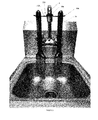
- FIG. 8 shows a drying clip in use, mounted on the spout of a water faucet, and hanging paint brushes.
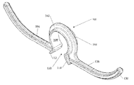
- FIG. 1 depicts a frontal perspective view of a drying clip 100 in accordance with a first, and preferred, embodiment of the present invention.
- the drying clip 100 may be configured from a variety of materials, including various plastics and metals. Preferred materials include polypropylene that may be molded in a mold. Regardless of the material, it is preferred that the drying clip 100 be resilient, such that it will recoil or spring back into shape after being bent, stretched, or compressed.
- the drying clip 100 is preferably a unitary piece, such as one formed monolithically within a mold.
- the drying clip 100 comprises a predominantly annular central portion 102 with two arms 104 , 106 extending in opposite directions therefrom. Preferably this extension is along a single plane.
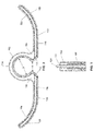
- a grasping portion 108 is formed within the central portion 102 as a constant radius arc having a length greater than that of a semi-circle. This grasping portion 108 preferably spans approximately 315°, leaving an opening 110 of approximately 45°. In other embodiments, the grasping portion 108 may span greater or less than 315°, with preferred embodiments leaving an opening 110 having an opening distance “A” less than the diameter “B” of the grasping portion 108 (see FIG. 2 ). In other embodiments, the grasping portion 108 may he other than a constant radius arc.
- the diameter “B” of the grasping portion 108 is less than the spout diameter of a conventional water faucet upon which the drying clip 100 will be placed, thus requiring the grasping portion 108 to be spread apart, temporarily lengthening the opening distance “A” (i.e. widening the opening), when fitted over a water faucet spout.
- the “S” dimension is generally to be construed as the minor, or shortest dimension, across the grasping portion.
- the “B” dimension is 18 mm. In other embodiments, the dimension may be less than 18 mm or greater than 18 mm, with preference to the dimensions of or between approximately 12 mm and 30 mm.
- the inside surface 109 of the grasping portion is shown as being smooth, but it may be textured or otherwise treated, such as with an additional component, to increase friction between the inside surface 109 and the member upon which it is mounted.
- terminus members 112 , 114 Defining the opening 110 of the central portion 102 are terminus members 112 , 114 .
- the terminus members 112 , 114 are each angled outwardly from a direction within the central portion 102 .
- the terminus members 112 ′, 114 ′ may be parallel to each other.
- the terminus members 112 ,, 114 may be abutted and pushed against a spout of a conventional water faucet, thus forcing the opening “A” to increase in length due to pressure upon, and cam action of, the angled terminus members.
- at least the grasping portion 108 is resilient so the opening “A” returns back to, or near to, its original length after mounting of the drying clip 100 on the spout.
- the drying clip 100 includes two arms 104 , 106 extending from the central portion 102 in opposite directions. Specifically, in the embodiment shown in FIG. 1 , the arms extend from the grasping portion 103 starting in the general area of the terminus members 112 , 114 , respectively, along a single plane.
- Each arm 104 , 106 initially extends parallel to one another in respective linear extension areas 116 , 118 until they reach inflection points 120 , 122 , and begin to bend in a direction, in the preferred embodiment, toward the head portion 124 of the grasping member 108 , defined as that portion opposite the opening 110 .
- the arms 104 , 106 may take on different geometric configurations.
- the drying clip includes a continuous flange 130 extending around the annular central portion 102 and two arms 104 , 106 .
- This continuous flange 130 provides additional material to the clip and offers strength for stiffening the arms 104 , 106 in particular, although it also stiffens the grasping portion 108 of the annular central portion 102 .
- the flange may only be provided along one or more portions of the grasping portion and arms and not the entire clip.
- the flange 130 forms a “cross-shaped” cross-section with the arms 104 , 106 of the clip.
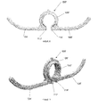
- FIGS. 6 and 7 show a drying clip 100 ′in accordance with a second embodiment of the present invention.
- the primary difference between the drying clip 100 ′ of this embodiment and that of the embodiment shown in FIGS. 1-5 are the arrangement of the terminus members 112 ′, 114 ′ being parallel to each other.
- the terminus members 112 ′, 114 ′ are parallel to each other.
- the drying clip 100 ′ also includes a grasping portion 108 ′ positioned between a pair of arms 104 ′, 106 ′, where the grasping portion has an inner surface 109 ′. Also provided is a flange 130 ′ extending around the grasping portion 108 ′ and the arms 104 ′, 106 ′. In this particular embodiment, it will be appreciated that the flange 130 ′ is not as pronounced in the arm area 104 ′, 106 ′ as in the area of the grasping portion 108 ′.
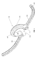
- FIG. 8 shows an example of a drying clip 100 in use, mounted on the spout “S” of a water faucet, and hanging paint brushes “PB” from the arms 104 , 106 .
- the drying clip 100 is fitted over the spout “S” by spreading the grasping portion 108 , fitting it over the spout, and then allowing it to rebound back to position fixed upon the spout. This automatically positions the arias outwardly as shown in FIG. 8 .
- the drying clip 100 is resilient. If non-resilient, the grasping portion may have to be manually returned to its smaller diameter size.
- Paint brushes “PB,” and specifically apertures formed in their handles, may then be threaded through the arms 104 , 106 respectively to hang the paint brushes for drying. While hanging, water trapped in the bristles of the paint brushes “PB” is permitted to drip into a sink. Notably, the curvature of the arms 104 , 106 aids in preventing the paint brushes “PB” from sliding off the arms, as they might if the arms were completely linear.
- drying clips shown and described herein can be fitted over other members, preferably those having circular cross-sections, such as pipes, conduits, and the like.
Landscapes
- Engineering & Computer Science (AREA)
- General Engineering & Computer Science (AREA)
- Mechanical Engineering (AREA)
- Drying Of Solid Materials (AREA)
Abstract
A drying clip for hanging articles from a member having a cross-sectional dimension, particularly a water faucet spout, the drying clip including a grasping portion forming an arc with a first end and a second end, and an opening between the ends, the opening having a dimension less than the cross-sectional dimension of the member; a first arm extending from the grasping portion; and, a second arm extending from said grasping portion. When the grasping portion is fitted around the member, the member supports the drying clip and articles hung from the first and second arms thereof. The first end and the second end may include terminus members angled outwardly to facilitate widening of the opening upon exertion of pressure thereon. The drying clip may include a flange extending along the grasping portion for stiffening the grasping portion.
Description
- The present application claims benefit of U.S. Provisional Patent Application Ser. No. 62/328,126, filed Apr. 27, 2016, entitled “Device/Clip On Faucet For The Ability To Allow Something To Hang Dry Over A Sink,” the disclosure of which is hereby incorporated by reference herein.
- The present invention relates to the hanging of articles, for example articles of manufacture, primarily for the purpose of drying. While such articles may include virtually any article, including tools, textiles, sponges, scrub brushes, footwear, and the like, the focus herein will be on paintbrushes.
- Most manufacturers of paintbrushes have recommended guidelines or procedures for cleaning and properly caring for a paintbrush following its use. Indeed, these guidelines or procedures often come printed on the paintbrush package itself. While the actual cleaning procedures may differ depending on the paint or stain having been used, for example whether it is oil or water based, most manufacturers recommend hanging the paintbrush to air dry after cleaning. Only after complete drying should the paintbrush be returned to its original package. This helps to maintain bristle integrity and shape.
- Despite the recommendation to hang a paintbrush for drying, to date there have been no completely suitable, simple, and clean solutions for hanging a brush. As such, a device to hang paintbrushes to dry is presented herein.
- In accordance with one embodiment of the invention, the invention provides for a drying clip for hanging articles from a member having a cross-sectional dimension, where the drying clip includes a grasping portion forming an arc with a first end and a second end, and an opening between the ends, the opening having a dimension less than the cross-sectional dimension of the member; a first arm extending from the grasping portion; a second arm extending from the grasping portion; wherein, when the grasping portion is fitted around the member, the member supports the drying clip and articles hung from the first and second arms thereof.
- The member may have a circular cross-section.
- The member may be a spout of a water faucet.
- The articles may be paint brushes.
- The drying clip may be unitarily formed.
- The arc may be of constant radius.
- The grasping portion may be resilient.
- The first end and the second end may include terminus members angled outwardly to facilitate widening of the opening upon exertion of pressure thereon.
- The first arm may extend from the grasping portion with a linear extension area thereof, the linear extension area extending to an inflection point.
- The dimension of the opening may be less than 18 mm.
- The drying clip may further comprise a flange extending along at least some portion of the grasping portion, first arm, and second arm, the flange providing strength for stiffening the drying clip.
- The first end and the second end may include terminus members angled outwardly to facilitate widening of the opening upon exertion of pressure thereon, and the drying clip may further include a flange extending along at least some portion of the grasping portion, first arm, arid second arm, the flange providing strength for stiffening the drying clip.
- In accordance with a further embodiment of the present invention, a clip for attaching to a member with a circular cross-section is provided, the clip including a resilient grasping portion having an opening, the resilient grasping portion having a minor dimension; and a first arm and a second arm extending from the grasping portion in opposite directions from one another; wherein the opening of the resilient grasping portion may be spread apart to expand the minor dimension to fit over the member, and subsequently released to resiliently impart pressure upon the member, thereby attaching the clip to the member.
- The minor dimension may be less than the diameter of the circular cross-section of the member.
- The clip may further include a flange extending along the grasping portion for stiffening the grasping portion.
- The clip may further include a flange extending along at least some portion of the resilient grasping portion, the first arm, and the second arm, for stiffening the drying clip.
- In a still further embodiment of the invention, a kit of components may include at least one paint brush; at least one drying clip, each of the at least one drying clips comprising a grasping portion forming an arc with a first end and a second end, and an opening between the ends; a first arm extending from the grasping portion; a second arm extending from the grasping portion; wherein the grasping portion of one of the at least one drying clip may be fitted around a member to support the one of the at least one drying clip and at least one of the at least one paint brush may be hung from at least one of the first arm and the second arm.
- Each of the at least one drying clips may further include a strengthening flange.
- The subject matter regarded as the invention is particularly pointed out and distinctly claimed in the concluding portion of the specification. The invention, however, both as to organization and method of operation, together with features, objects, and advantages thereof, will be or become apparent to one with skill in the art upon reference to the following detailed description when read with the accompanying drawings. It is intended that any additional organizations, methods of operation, features, objects or advantages ascertained by one skilled in the art be included within this description, be within the scope of the present invention, and be protected by the accompanying claims.
- With respect to the drawings,
FIG. 1 shows a frontal perspective view of a drying clip in accordance with a first embodiment of the present invention; -
FIG. 2 shows a front view of the drying clip ofFIG. 1 ; -
FIG. 3 shows a side view of the drying clip ofFIG. 1 , the other side view being a mirror image; -
FIG. 4 shows a top view of the drying clip ofFIG. 1 ; -
FIG. 5 shows a bottom view of the drying clip ofFIG. 1 ; -
FIG. 6 shows a front view of a drying clip in accordance with a second embodiment of the present invention; -
FIG. 7 shows a frontal perspective view of the drying clip ofFIG. 6 ; and, -
FIG. 8 shows a drying clip in use, mounted on the spout of a water faucet, and hanging paint brushes. - In the following are described the preferred embodiments of the DRYING CLIP in accordance with the present invention. In describing the embodiments illustrated in the drawings, specific terminology will be used for the sake of clarity. However, the invention is not intended to be limited to the specific terms so selected, and it is to be understood that each specific term includes all technical equivalents that operate in a similar manner
- to accomplish a similar purpose. Where like elements nave been depicted in multiple embodiments, identical reference numerals have been used in the multiple embodiments for ease of understanding.
-
FIG. 1 depicts a frontal perspective view of adrying clip 100 in accordance with a first, and preferred, embodiment of the present invention. Thedrying clip 100 may be configured from a variety of materials, including various plastics and metals. Preferred materials include polypropylene that may be molded in a mold. Regardless of the material, it is preferred that thedrying clip 100 be resilient, such that it will recoil or spring back into shape after being bent, stretched, or compressed. - As shown in
FIG. 1 , thedrying clip 100 is preferably a unitary piece, such as one formed monolithically within a mold. Thedrying clip 100 comprises a predominantly annularcentral portion 102 with twoarms - A
grasping portion 108 is formed within thecentral portion 102 as a constant radius arc having a length greater than that of a semi-circle. This graspingportion 108 preferably spans approximately 315°, leaving anopening 110 of approximately 45°. In other embodiments, thegrasping portion 108 may span greater or less than 315°, with preferred embodiments leaving an opening 110 having an opening distance “A” less than the diameter “B” of the grasping portion 108 (seeFIG. 2 ). In other embodiments, thegrasping portion 108 may he other than a constant radius arc. - As will be discussed below, in preferred embodiments, the diameter “B” of the
grasping portion 108 is less than the spout diameter of a conventional water faucet upon which thedrying clip 100 will be placed, thus requiring thegrasping portion 108 to be spread apart, temporarily lengthening the opening distance “A” (i.e. widening the opening), when fitted over a water faucet spout. In other embodiments where thegrasping portion 108 may foe other than a constant radius arc, the “S” dimension is generally to be construed as the minor, or shortest dimension, across the grasping portion. - In the preferred embodiment, the “B” dimension is 18 mm. In other embodiments, the dimension may be less than 18 mm or greater than 18 mm, with preference to the dimensions of or between approximately 12 mm and 30 mm.
- The
inside surface 109 of the grasping portion is shown as being smooth, but it may be textured or otherwise treated, such as with an additional component, to increase friction between theinside surface 109 and the member upon which it is mounted. - Defining the
opening 110 of thecentral portion 102 areterminus members FIG. 1 , theterminus members central portion 102. In other embodiments, for example the embodiment of the invention shown inFIGS. 6-7 , theterminus members 112′, 114′ may be parallel to each other. By being angled outwardly, theterminus members portion 108 is resilient so the opening “A” returns back to, or near to, its original length after mounting of thedrying clip 100 on the spout. - As previously mentioned, the drying
clip 100 includes twoarms central portion 102 in opposite directions. Specifically, in the embodiment shown inFIG. 1 , the arms extend from the grasping portion 103 starting in the general area of theterminus members - Each
arm linear extension areas inflection points head portion 124 of the graspingmember 108, defined as that portion opposite theopening 110. Beyond theinflection points curved portions arms arms - Although not required, in the embodiment of the
drying clip 100 shown inFIGS. 1-5 , the drying clip includes acontinuous flange 130 extending around the annularcentral portion 102 and twoarms continuous flange 130 provides additional material to the clip and offers strength for stiffening thearms portion 108 of the annularcentral portion 102. In other embodiments the flange may only be provided along one or more portions of the grasping portion and arms and not the entire clip. In preferred embodiments, theflange 130 forms a “cross-shaped” cross-section with thearms - As previously discussed,
FIGS. 6 and 7 show adrying clip 100′in accordance with a second embodiment of the present invention. The primary difference between the dryingclip 100′ of this embodiment and that of the embodiment shown inFIGS. 1-5 are the arrangement of theterminus members 112′, 114′ being parallel to each other. In this regard, in order to install thedrying clip 100′ over a water faucet spout, one much manually spread theterminus members 112′, 114′ apart to enlarge the distance between them. - For completeness, it is noted that the
drying clip 100′ also includes a graspingportion 108′ positioned between a pair ofarms 104′, 106′, where the grasping portion has aninner surface 109′. Also provided is aflange 130′ extending around the graspingportion 108′ and thearms 104′, 106′. In this particular embodiment, it will be appreciated that theflange 130′ is not as pronounced in thearm area 104′, 106′ as in the area of the graspingportion 108′. -
FIG. 8 shows an example of adrying clip 100 in use, mounted on the spout “S” of a water faucet, and hanging paint brushes “PB” from thearms clip 100 is fitted over the spout “S” by spreading the graspingportion 108, fitting it over the spout, and then allowing it to rebound back to position fixed upon the spout. This automatically positions the arias outwardly as shown inFIG. 8 . It will be appreciated that in this scenario the dryingclip 100 is resilient. If non-resilient, the grasping portion may have to be manually returned to its smaller diameter size. - Paint brushes “PB,” and specifically apertures formed in their handles, may then be threaded through the
arms arms - Although reference has been made to water faucets and their spouts, the drying clips shown and described herein can be fitted over other members, preferably those having circular cross-sections, such as pipes, conduits, and the like.
- Although the invention herein has been described with reference to particular embodiments, it is to be understood that these embodiments are illustrative of the principles and applications of the present invention. It is therefore to be understood that numerous modifications may be made to the illustrative embodiments and that other arrangements may be devised without departing from the spirit and scope of the present invention as defined by the appended claims.
Claims (18)
1. A drying clip for hanging articles from a member having a cross-sectional dimension, said drying clip comprising:
a grasping portion forming an arc with a first end and a second end, and an opening between said ends, said opening having a dimension less than the cross-sectional dimension of the member;
a first arm extending from said grasping portion;
a second arm extending from said grasping portion;
wherein, when said grasping portion is fitted around the member, the member supports the drying clip and articles hung from the first and second arms thereof.
2. The drying clip of claim 1 , wherein said member has circular cross-section.
3. The drying clip of claim 1 , wherein said member is a spout of a water faucet.
4. The drying clip of claim 1 , wherein said articles are paint brushes.
5. The drying clip of claim 1 , wherein said drying clip is unitarily formed.
6. The drying clip of claim 1 , wherein said arc is of constant radius.
7. The drying clip of claim 1 , wherein said grasping portion is resilient.
8. The drying clip oi claim wherein said first end and said second end include terminus members angled outwardly to facilitate widening of said opening upon exertion of pressure thereon.
9. The drying clip of claim 1 , wherein said first arm extends from said grasping portion with a linear extension area thereof, said linear extension area extending to an inflection point.
10. The drying clip of claim 1 , wherein said dimension of said Opening is less than 18 mm.
11. The drying clip of claim 1 , further comprising a flange extending along at least some portion of said grasping portion, first arm, and second arm, said flange providing strength for stiffening the drying clip.
12. The drying clip of claim 8 , further comprising a flange extending along at least some portion of said grasping portion, first arm, and second arm, said flange providing strength for stiffening the drying clip.
13. A clip for attaching to a member with a circular cross-section, said clip comprising:
a resilient grasping portion having an opening, said resilient grasping portion having a minor dimension;
a first arm and a second arm extending from said grasping portion in opposite directions from one another;
wherein said opening of said resilient grasping portion may be spread apart to expand said minor dimension to fit over the member, and subsequently released to resiliently impart pressure upon the member, thereby attaching the clip to the member.
14. The clip of claim 13 , wherein said minor dimension is less than the diameter of the circular cross-section of the member.
15. The clip of claim 13 , further comprising a flange extending along said grasping portion for stiffening the grasping portion.
16. The clip of claim 13 , further comprising a flange extending along at least some portion of said resilient grasping portion, said first arm, and said second arm, for stiffening the drying clip.
17. A kit of components, said kit comprising: at least one paint brush;
at least one drying clip, each of said at least one drying clip comprising:
a grasping portion forming an arc with a first end and a second end, and an opening between said ends;
a first arm extending from said grasping portion;
a second arm extending from said grasping portion;
wherein said grasping portion of one of said at least one drying clip may be fitted around a member to support said one of said at least one drying clip and at least one of said at least one paint brush may be hung from at least one of said first arm and said second arm.
18. The kit of claim 17 , wherein each of said at least one drying clips further comprises a strengthening flange.
Priority Applications (1)
| Application Number | Priority Date | Filing Date | Title |
|---|---|---|---|
| US15/499,772 US20180098654A1 (en) | 2016-04-27 | 2017-04-27 | Drying clip |
Applications Claiming Priority (2)
| Application Number | Priority Date | Filing Date | Title |
|---|---|---|---|
| US201662328126P | 2016-04-27 | 2016-04-27 | |
| US15/499,772 US20180098654A1 (en) | 2016-04-27 | 2017-04-27 | Drying clip |
Publications (1)
| Publication Number | Publication Date |
|---|---|
| US20180098654A1 true US20180098654A1 (en) | 2018-04-12 |
Family
ID=61829589
Family Applications (1)
| Application Number | Title | Priority Date | Filing Date |
|---|---|---|---|
| US15/499,772 Abandoned US20180098654A1 (en) | 2016-04-27 | 2017-04-27 | Drying clip |
Country Status (1)
| Country | Link |
|---|---|
| US (1) | US20180098654A1 (en) |
Cited By (2)
| Publication number | Priority date | Publication date | Assignee | Title |
|---|---|---|---|---|
| USD914157S1 (en) | 2019-08-16 | 2021-03-23 | Harrison Rogers | Faucet attachment |
| US20240251980A1 (en) * | 2023-01-30 | 2024-08-01 | Margarita Christie | System and method for a handbag holding apparatus at restaurants |
-
2017
- 2017-04-27 US US15/499,772 patent/US20180098654A1/en not_active Abandoned
Cited By (2)
| Publication number | Priority date | Publication date | Assignee | Title |
|---|---|---|---|---|
| USD914157S1 (en) | 2019-08-16 | 2021-03-23 | Harrison Rogers | Faucet attachment |
| US20240251980A1 (en) * | 2023-01-30 | 2024-08-01 | Margarita Christie | System and method for a handbag holding apparatus at restaurants |
Similar Documents
| Publication | Publication Date | Title |
|---|---|---|
| USD822298S1 (en) | Combination scrubbing sponge with handle and holder | |
| US10717318B2 (en) | Universal paint brush holder for paint buckets | |
| US11266227B1 (en) | Power driven duster and cleaner apparatus | |
| US9073198B1 (en) | Flexible utility handle | |
| CN107073701A (en) | Keeper for object | |
| US20180098654A1 (en) | Drying clip | |
| US10194740B2 (en) | Fluid dispensing brush assembly | |
| KR101848846B1 (en) | Washing brush for cleaning various sizes of containers | |
| US8915355B2 (en) | Flux applicator brush and flux container system | |
| US20180344520A1 (en) | Contact lens insertion assisting assembly | |
| US766169A (en) | Brush-holder. | |
| US20210120946A1 (en) | Cleaning Attachment Assembly | |
| US674962A (en) | Window-cleaner. | |
| US20090057500A1 (en) | Method and apparatus to dry paint brushes | |
| US1263925A (en) | Brush-holder. | |
| US2661491A (en) | Brush | |
| US1199837A (en) | Shaving-brush. | |
| US2948910A (en) | No drip brush attachment | |
| US10548458B1 (en) | Tethered cleaning tool for a kitchen sink | |
| KR200478530Y1 (en) | Supporter for removing foreign matter | |
| JP2011083435A (en) | Holder for cleaning tool, and cleaning tool | |
| US20160051117A1 (en) | Cleaning wand and cloth system | |
| US20160183734A1 (en) | Toiletry item stand | |
| US373780A (en) | Broom-holder | |
| US2908927A (en) | Hand brush |
Legal Events
| Date | Code | Title | Description |
|---|---|---|---|
| STCB | Information on status: application discontinuation |
Free format text: ABANDONED -- FAILURE TO RESPOND TO AN OFFICE ACTION |