US20180098554A1 - Method for making liquid or semi-liquid products and machine to implement the method - Google Patents
Method for making liquid or semi-liquid products and machine to implement the method Download PDFInfo
- Publication number
- US20180098554A1 US20180098554A1 US15/720,846 US201715720846A US2018098554A1 US 20180098554 A1 US20180098554 A1 US 20180098554A1 US 201715720846 A US201715720846 A US 201715720846A US 2018098554 A1 US2018098554 A1 US 2018098554A1
- Authority
- US
- United States
- Prior art keywords
- liquid
- semi
- container
- processing container
- liquid product
- Prior art date
- Legal status (The legal status is an assumption and is not a legal conclusion. Google has not performed a legal analysis and makes no representation as to the accuracy of the status listed.)
- Granted
Links
- 239000007788 liquid Substances 0.000 title claims abstract description 99
- 239000012263 liquid product Substances 0.000 title claims abstract description 95
- 238000000034 method Methods 0.000 title claims description 21
- 230000002401 inhibitory effect Effects 0.000 claims abstract description 29
- 238000001816 cooling Methods 0.000 claims abstract description 12
- 238000003756 stirring Methods 0.000 claims description 9
- 238000007669 thermal treatment Methods 0.000 claims description 4
- 239000012530 fluid Substances 0.000 claims description 3
- 238000004891 communication Methods 0.000 claims description 2
- 239000000047 product Substances 0.000 description 13
- 235000015243 ice cream Nutrition 0.000 description 11
- 230000000694 effects Effects 0.000 description 3
- 238000004140 cleaning Methods 0.000 description 2
- 235000013305 food Nutrition 0.000 description 2
- 235000021056 liquid food Nutrition 0.000 description 2
- 238000004519 manufacturing process Methods 0.000 description 2
- 239000008267 milk Substances 0.000 description 2
- 210000004080 milk Anatomy 0.000 description 2
- 235000013336 milk Nutrition 0.000 description 2
- 230000003134 recirculating effect Effects 0.000 description 2
- 238000007789 sealing Methods 0.000 description 2
- 235000021057 semi-liquid food Nutrition 0.000 description 2
- 235000003363 Cornus mas Nutrition 0.000 description 1
- 240000006766 Cornus mas Species 0.000 description 1
- 235000013399 edible fruits Nutrition 0.000 description 1
- 239000000796 flavoring agent Substances 0.000 description 1
- 235000019634 flavors Nutrition 0.000 description 1
- 239000004615 ingredient Substances 0.000 description 1
- 230000001788 irregular Effects 0.000 description 1
- 239000007769 metal material Substances 0.000 description 1
- 238000002360 preparation method Methods 0.000 description 1
Images

Classifications
-
- A—HUMAN NECESSITIES
- A23—FOODS OR FOODSTUFFS; TREATMENT THEREOF, NOT COVERED BY OTHER CLASSES
- A23G—COCOA; COCOA PRODUCTS, e.g. CHOCOLATE; SUBSTITUTES FOR COCOA OR COCOA PRODUCTS; CONFECTIONERY; CHEWING GUM; ICE-CREAM; PREPARATION THEREOF
- A23G9/00—Frozen sweets, e.g. ice confectionery, ice-cream; Mixtures therefor
- A23G9/04—Production of frozen sweets, e.g. ice-cream
- A23G9/08—Batch production
- A23G9/12—Batch production using means for stirring the contents in a non-moving container
-
- A—HUMAN NECESSITIES
- A23—FOODS OR FOODSTUFFS; TREATMENT THEREOF, NOT COVERED BY OTHER CLASSES
- A23G—COCOA; COCOA PRODUCTS, e.g. CHOCOLATE; SUBSTITUTES FOR COCOA OR COCOA PRODUCTS; CONFECTIONERY; CHEWING GUM; ICE-CREAM; PREPARATION THEREOF
- A23G9/00—Frozen sweets, e.g. ice confectionery, ice-cream; Mixtures therefor
- A23G9/04—Production of frozen sweets, e.g. ice-cream
- A23G9/22—Details, component parts or accessories of apparatus insofar as not peculiar to a single one of the preceding groups
- A23G9/222—Freezing drums
-
- A—HUMAN NECESSITIES
- A23—FOODS OR FOODSTUFFS; TREATMENT THEREOF, NOT COVERED BY OTHER CLASSES
- A23G—COCOA; COCOA PRODUCTS, e.g. CHOCOLATE; SUBSTITUTES FOR COCOA OR COCOA PRODUCTS; CONFECTIONERY; CHEWING GUM; ICE-CREAM; PREPARATION THEREOF
- A23G9/00—Frozen sweets, e.g. ice confectionery, ice-cream; Mixtures therefor
- A23G9/04—Production of frozen sweets, e.g. ice-cream
- A23G9/045—Production of frozen sweets, e.g. ice-cream of slush-ice, e.g. semi-frozen beverage
-
- A—HUMAN NECESSITIES
- A23—FOODS OR FOODSTUFFS; TREATMENT THEREOF, NOT COVERED BY OTHER CLASSES
- A23G—COCOA; COCOA PRODUCTS, e.g. CHOCOLATE; SUBSTITUTES FOR COCOA OR COCOA PRODUCTS; CONFECTIONERY; CHEWING GUM; ICE-CREAM; PREPARATION THEREOF
- A23G9/00—Frozen sweets, e.g. ice confectionery, ice-cream; Mixtures therefor
- A23G9/04—Production of frozen sweets, e.g. ice-cream
- A23G9/14—Continuous production
- A23G9/18—Continuous production the products being on the outer wall of a cooled body, e.g. drum or endless band
-
- A—HUMAN NECESSITIES
- A23—FOODS OR FOODSTUFFS; TREATMENT THEREOF, NOT COVERED BY OTHER CLASSES
- A23G—COCOA; COCOA PRODUCTS, e.g. CHOCOLATE; SUBSTITUTES FOR COCOA OR COCOA PRODUCTS; CONFECTIONERY; CHEWING GUM; ICE-CREAM; PREPARATION THEREOF
- A23G9/00—Frozen sweets, e.g. ice confectionery, ice-cream; Mixtures therefor
- A23G9/04—Production of frozen sweets, e.g. ice-cream
- A23G9/22—Details, component parts or accessories of apparatus insofar as not peculiar to a single one of the preceding groups
- A23G9/228—Arrangement and mounting of control or safety devices
-
- A—HUMAN NECESSITIES
- A23—FOODS OR FOODSTUFFS; TREATMENT THEREOF, NOT COVERED BY OTHER CLASSES
- A23G—COCOA; COCOA PRODUCTS, e.g. CHOCOLATE; SUBSTITUTES FOR COCOA OR COCOA PRODUCTS; CONFECTIONERY; CHEWING GUM; ICE-CREAM; PREPARATION THEREOF
- A23G9/00—Frozen sweets, e.g. ice confectionery, ice-cream; Mixtures therefor
- A23G9/04—Production of frozen sweets, e.g. ice-cream
- A23G9/22—Details, component parts or accessories of apparatus insofar as not peculiar to a single one of the preceding groups
- A23G9/28—Details, component parts or accessories of apparatus insofar as not peculiar to a single one of the preceding groups for portioning or dispensing
- A23G9/281—Details, component parts or accessories of apparatus insofar as not peculiar to a single one of the preceding groups for portioning or dispensing at the discharge end of freezing chambers
-
- A—HUMAN NECESSITIES
- A23—FOODS OR FOODSTUFFS; TREATMENT THEREOF, NOT COVERED BY OTHER CLASSES
- A23G—COCOA; COCOA PRODUCTS, e.g. CHOCOLATE; SUBSTITUTES FOR COCOA OR COCOA PRODUCTS; CONFECTIONERY; CHEWING GUM; ICE-CREAM; PREPARATION THEREOF
- A23G9/00—Frozen sweets, e.g. ice confectionery, ice-cream; Mixtures therefor
- A23G9/04—Production of frozen sweets, e.g. ice-cream
- A23G9/22—Details, component parts or accessories of apparatus insofar as not peculiar to a single one of the preceding groups
- A23G9/28—Details, component parts or accessories of apparatus insofar as not peculiar to a single one of the preceding groups for portioning or dispensing
- A23G9/288—Details, component parts or accessories of apparatus insofar as not peculiar to a single one of the preceding groups for portioning or dispensing for finishing or filling ice-cream cones or other edible containers; Manipulating methods therefor
-
- A—HUMAN NECESSITIES
- A23—FOODS OR FOODSTUFFS; TREATMENT THEREOF, NOT COVERED BY OTHER CLASSES
- A23G—COCOA; COCOA PRODUCTS, e.g. CHOCOLATE; SUBSTITUTES FOR COCOA OR COCOA PRODUCTS; CONFECTIONERY; CHEWING GUM; ICE-CREAM; PREPARATION THEREOF
- A23G9/00—Frozen sweets, e.g. ice confectionery, ice-cream; Mixtures therefor
- A23G9/04—Production of frozen sweets, e.g. ice-cream
- A23G9/22—Details, component parts or accessories of apparatus insofar as not peculiar to a single one of the preceding groups
- A23G9/224—Agitators or scrapers
-
- A—HUMAN NECESSITIES
- A23—FOODS OR FOODSTUFFS; TREATMENT THEREOF, NOT COVERED BY OTHER CLASSES
- A23V—INDEXING SCHEME RELATING TO FOODS, FOODSTUFFS OR NON-ALCOHOLIC BEVERAGES AND LACTIC OR PROPIONIC ACID BACTERIA USED IN FOODSTUFFS OR FOOD PREPARATION
- A23V2300/00—Processes
- A23V2300/24—Heat, thermal treatment
Definitions
- This invention relates to a method for making liquid or semi-liquid products and a machine configured to implement this method.
- the aim of this invention is to provide a method and a machine for making a liquid or semi-liquid product, specifically ice cream, and which allow the above mentioned needs to be met.
- the aim of this invention is therefore to provide a method and a machine for making a liquid or semi-liquid product, specifically ice cream, and which allow obtaining a liquid or semi-liquid product of high quality (with a good level of repeatability).
- the aim of this invention is therefore to provide a method and a machine for making a liquid or semi-liquid product, specifically ice cream, and which allow obtaining a liquid or semi-liquid product particularly rapidly.
- Yet another aim of this invention is to provide a method and a machine for making a liquid or semi-liquid product, specifically ice cream, and whose operation is particularly simple and effective.
- this aim is achieved by a method and a machine for making liquid or semi-liquid products and comprising the technical features set out in one or more of the appended claims.
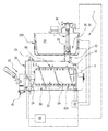
- FIG. 1 is a schematic view of a first embodiment of a machine according to this invention
- FIGS. 2 and 3 are respective schematic views of a detail of the machine of FIG. 1 , forming the object of this invention
- FIGS. 4 to 8 are respective schematic views of another detail of the machine of FIG. 1 , forming the object of this invention.
- FIG. 9 shows a detail of a machine forming the object of this invention as shown in FIG. 1 , according to a first embodiment
- FIG. 10 shows a detail of a machine forming the object of this invention as shown in FIG. 1 , according to a second embodiment.
- the numeral 1 denotes a machine forming the object of this invention, for making liquid or semi-liquid products.
- the machine is preferably adapted to make ice cream (artisan gelato or soft ice cream) or products for the ice cream trade (granitas, sorbets, etc.).
- ice cream is used to mean a food preparation which is based on milk or milk-derived products and to which fruit, aromatics or other ingredients are added to obtain different flavors.
- the machine 1 for making liquid or semi-liquid products comprises:
- a first processing container 2 for processing a basic liquid or semi-liquid product and defining a processing chamber 3 ; a cooling cylinder 20 mounted inside the first container 2 ; a second processing container 21 ; a connecting duct 52 between the first container 2 and the second container 21 ; a dispensing device 23 associated with the first processing container 2 and configured, in a dispensing configuration, to deliver the liquid or semi-liquid product to the outside or, in an inhibiting configuration, to prevent the liquid or semi-liquid product from being dispensed; a shutoff valve 26 configured, in a closed configuration, to close the connecting duct 52 between the first container 2 and the second container 21 or, in an open configuration, to open the connecting duct 52 between the first container 2 and the second container 21 ; a control unit 60 operatively connected to the dispensing device 23 to detect the dispensing or inhibiting configuration thereof, and to the shutoff valve 26 in order to drive it between the closed configuration and the open configuration, the control unit 60 being configured to drive the shutoff valve 26 in such a way as to
- the machine comprises a rotary stirrer 5 mounted inside the chamber 3 (that is, inside the first processing container 2 ) and outside the cooling cylinder 20 .
- the machine comprises a thermal treatment system 22 provided with at least a first exchanger associated with the cooling cylinder 20 (mounted inside the cooling cylinder 20 to cool and/or heat an outside surface of the cooling cylinder 20 ).
- the first processing container 2 for processing a basic liquid or semi-liquid product comprises a radially protruding longitudinal portion 2 A defining a zone (between the front section and the rear section) for recirculating the basic liquid or semi-liquid product when the rotary stirrer 5 is set in rotation.
- the portion 2 A defines, along the main direction of extension of the processing container 2 , a radial protrusion which also extends radially and along the main direction of extension of the processing container 2 .
- the radially protruding longitudinal portion 2 A allows the food product inside the first container 2 to be recirculated by pushing it axially, that is, longitudinally, by effect of the rotational motion of the rotary stirrer 5 (thanks to at least one helical portion of the rotary stirrer 5 ).
- the longitudinal portion 2 A defines a compartment within which the product can move (longitudinally, that is, along the axis of the rotary stirrer 5 , from the front section to the rear section) under the pushing action of the rotary stirrer 5 .
- This recirculating action allows optimum, uniform processing of the product, preventing the product from accumulating in the front zone (which would result in non-uniform temperature).
- heat exchanger 22 A is mounted inside the cooling cylinder 20 .
- the cooling cylinder 20 is made of metallic material.
- the first processing container 2 has, in transverse cross section, a first portion 2 B which is substantially circular and a second portion 2 A, connected thereto, which is irregular in shape (that is, the aforementioned radially protruding, longitudinal portion 2 A) and which defines an external extension of the first portion 2 B.
- the rotary stirrer 5 has a helically extending portion 5 A.
- the stirrer 5 preferably also comprises a pair of stiffening elements 5 B, 5 B extending longitudinally and coupled to the helical portion 5 A in order to stiffen the helical portion 5 A.
- the second container 21 is a tub-like container.
- the second container 21 is openable at the top.
- the second container 21 too, has a stirrer mounted in it to stir the liquid or semi-liquid product present in the second container 21 .
- the machine 1 comprises a second heat exchanger 22 B associated with the second container 21 .
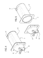
- shutoff valve 26 Described below is the shutoff valve 26 according to the embodiment illustrated in the accompanying drawings.
- the machine 1 comprises a transfer device 30 for transferring the basic liquid or semi-liquid product from the second container 21 to the first container 2 .
- the transfer device 30 comprises the duct 52 connecting the second container 21 to the first container 2 .
- the first container 2 has a first opening 32 made in it (the first opening 32 being preferably, but not necessarily, made in the radially protruding, longitudinal portion 2 A).
- the second container 21 has a second opening 33 made in it (the second opening 33 being preferably, but not necessarily, made on the bottom of the second container 21 ).
- the connecting duct 52 connects the first opening 32 to the second opening 33 .
- the further duct 34 terminates at the second opening 33 .
- the further duct 34 is internally hollow, that is to say, it has an internal cavity passing longitudinally through it.
- the further duct 34 is movable vertically between a shutoff position, where the connection between the second container 21 and the first container 2 is closed, and an open position, where the connection between the second container 21 and the first container 2 is open.
- the further duct 34 has, at the bottom of it, a radially external sealing zone (this sealing zone being preferably defined by a gasket 37 ).
- gasket 37 is preferably internally hollow so that it can establish fluid communication, through its internal cavity, with the internal cavity of the duct 34 .
- the duct 34 is movable and defines the aforementioned shutoff valve 26 (the gasket 37 inhibits or establishes the connection between the second container 21 and the first container 2 ).
- air is made to pass through the internal cavity of the duct 34 .
- the duct 34 has an opening 38 which allows air into the cavity of the duct 34 itself.
- the machine 1 comprises a one-way (non-return) valve associated with the duct 34 , specifically with the opening 38 (at the top) to allow air to flow into the internal cavity of the duct 34 in one direction only.
- the machine 1 also comprises an actuator 48 adapted to open and close the shutoff valve 26 .
- the actuator 48 operates on the further duct 34 to allow movement (vertical) between the shutoff position for closing the passage of the basic liquid from the second container 21 to the first container 2 (through the connecting duct 52 ) and the open position for opening the passage of the basic liquid from the second container 21 to the first container 2 (through the connecting duct 52 ).
- the actuator 48 comprises a motor.
- the actuator 48 also comprises a guide 39 , more specifically, a pair of guides 39 , and a slide 40 movably coupled to the guide 39 .
- the guides 39 extend vertically.
- the guides 39 are preferably connected integrally to the frame of the machine 1 .
- the motor is kinematically connected to the slide 40 to allow it to move relative to the guides 39 .
- the dispensing device 23 comprises an outlet duct 24 and a shutter 42 , mounted movably in the outlet duct 24 to close it or leave it open.
- the shutter 42 can be actuated manually or automatically.
- the shutter 42 In order to dispense the product, the shutter 42 is moved to the open position and, preferably, the rotary stirrer 5 is set in rotation.
- the processing container 2 comprises a front portion 25 which is removable to allow the container 2 to be cleaned.
- the container 2 comprises a longitudinal portion 42 , to the front of which the removable portion 25 is coupled.
- the front portion 25 is therefore uncoupled from the longitudinal portion 42 only to allow the inside of the container 2 to be cleaned when the container 2 is empty.
- the liquid or semi-liquid product is dispensed through the outlet duct 24 .
- control unit 60 is configured to drive the shutoff valve 26 in such a way as to set it to the open configuration if the dispensing device 23 is in the inhibiting configuration.
- control unit 60 is configured to drive the shutoff valve 26 in such a way as to set it to the open configuration/position when the dispensing device 23 switches from the dispensing configuration to the inhibiting configuration.
- control unit 60 when the dispensing device 23 is set to the inhibiting configuration, the control unit 60 is configured to drive the shutoff valve 26 in such a way as to set it to the open configuration/position.
- control unit 60 is configured to keep the shutoff valve 26 in the open configuration/position for long enough to top up the first container 2 with the amount of liquid or semi-liquid product which has been dispensed from the first container 2 .
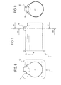
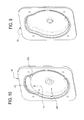
- FIG. 9 shows a first embodiment of the front portion 25 (door) which is removable to allow cleaning the processing container 2 .
- the front portion 25 (door) has a cavity made in it whose shape, in cross section, is substantially mirror symmetrical to that of the container 2 , in cross section.
- the cavity comprises a circular edge portion having a radially protruding region.
- FIG. 10 shows a second embodiment of the front portion 25 (door) which is removable to allow cleaning the processing container 2 .
- the front portion 25 has a first cavity 25 A made in it whose shape, in cross section, is circular.
- the front portion 25 (door) comprises a second cavity 25 B, less deep than, and separate from, the first cavity 25 A.
- the second cavity 25 B is separated from the first cavity 25 A by a pair of walls P 1 , P 2 .
- defined according to the invention is a method for making liquid or semi-liquid products, comprising the following steps:
- a cooling cylinder 20 mounted inside the first container 2 ;
- a dispensing device 23 associated with the first processing container 2 and configured, in a dispensing configuration, to deliver the liquid or semi-liquid product to the outside or, in an inhibiting configuration, to prevent the liquid or semi-liquid product from being dispensed;
- the machine 1 comprises a shutoff valve 26 configured to close a connecting duct 52 between the first container 2 and the second container 21 and the step of inhibiting transfer of the basic liquid or semi-liquid product from the second processing container 21 to the first processing container 2 comprises a step of closing the valve 26 and the step of transferring the basic liquid or semi-liquid product from the second processing container 21 to the first processing container 2 , after stirring and thermal treatment, comprises a step of opening the valve
- the shutoff valve 26 is defined by a duct 34 provided with an internal longitudinal through cavity, the further duct 34 being movable vertically between a closed position where the connecting duct 52 is closed and an open position where the connecting duct 52 is open, and the step of closing the valve 26 comprises a step of setting the duct 34 to the closed position and the step of opening the valve 26 comprises a step of setting the duct 34 to the open position.
- the step of transferring the basic liquid or semi-liquid product from the second processing container 21 to the first processing container 2 comprises a step of letting air into the internal cavity of the duct 34 in order to allow the air to be mixed into the liquid or semi-liquid product being transferred from the second processing container 21 to the first processing container 2 .
- the step of letting air into the internal cavity of the duct 34 comprises a step of causing the air to pass through a one-way valve 61 associated with the duct 34 .
- the step of setting the dispensing device 23 to the dispensing configuration to allow dispensing the liquid or semi-liquid product from the first processing container 2 while inhibiting transfer of the basic liquid or semi-liquid product from the second processing container 21 to the first container 2 comprises a step of dispensing a desired quantity of liquid or semi-liquid product, followed, at the end of the step of dispensing a desired quantity of liquid or semi-liquid product, by a step of setting the dispensing device 23 to the inhibiting configuration and then transferring from the second processing container 21 to the first processing container 2 a quantity of liquid or semi-liquid product substantially equal to the desired quantity of liquid or semi-liquid product dispensed so as to top up the first container 2 with the same amount of liquid or semi-liquid product as that dispensed.
- the first container 2 is topped up with the same amount of product as that dispensed (by transferring it from the second container 21 to the first container 2 ).
- the duct 34 is moved from the closed position to the open position for long enough to transfer to the first container 2 a quantity of basic liquid or semi-liquid product sufficient to replace the liquid or semi-liquid product which has been dispensed.
- the amount of liquid or semi-liquid product inside the first container 2 is kept substantially constant.
- the method comprises a step of stopping the transfer of basic liquid or semi-liquid product from the second processing container 21 to the first container 2 , this step being carried out after the steps of setting the dispensing device 23 to the inhibiting configuration and then transferring from the second processing container 21 to the first processing container 2 a quantity of liquid or semi-liquid product substantially equal to the desired quantity of liquid or semi-liquid product dispensed so as to top up the first container 2 with the same amount of liquid or semi-liquid product as that dispensed.
- the invention provides a machine 1 and a method which guarantee quality/repeatability of the finished product while at the same time reducing overall serving times (bearing in mind that the amount of liquid topped up must be frozen before being served).
- this type of machine is capable of making ice cream products (traditional and/or soft ice cream) as well as frozen products for the ice cream trade (e.g. granitas).
Landscapes
- Engineering & Computer Science (AREA)
- Life Sciences & Earth Sciences (AREA)
- Chemical & Material Sciences (AREA)
- Food Science & Technology (AREA)
- Polymers & Plastics (AREA)
- Manufacturing & Machinery (AREA)
- Confectionery (AREA)
- Crystals, And After-Treatments Of Crystals (AREA)
Abstract
Description
- This application claims priority to Italian Patent Application 102016000100959 filed Oct. 7, 2016, the entirety of which is incorporated by reference herein.
- This invention relates to a method for making liquid or semi-liquid products and a machine configured to implement this method.
- In the sector concerned there is a strongly felt need for production methods and machines which allow making high-quality liquid or semi-liquid food products with a high level of repeatability.
- Another strongly felt need in the sector is that for production methods and machines which allow making liquid or semi-liquid food products in a particularly quick and easy manner.
- The aim of this invention is to provide a method and a machine for making a liquid or semi-liquid product, specifically ice cream, and which allow the above mentioned needs to be met.
- More precisely, the aim of this invention is therefore to provide a method and a machine for making a liquid or semi-liquid product, specifically ice cream, and which allow obtaining a liquid or semi-liquid product of high quality (with a good level of repeatability).
- More precisely, the aim of this invention is therefore to provide a method and a machine for making a liquid or semi-liquid product, specifically ice cream, and which allow obtaining a liquid or semi-liquid product particularly rapidly.
- Yet another aim of this invention is to provide a method and a machine for making a liquid or semi-liquid product, specifically ice cream, and whose operation is particularly simple and effective.
- According to the invention, this aim is achieved by a method and a machine for making liquid or semi-liquid products and comprising the technical features set out in one or more of the appended claims.
- The technical features of the invention, with reference to the above aims, are clearly described in the annexed claims and its advantages are more apparent from the detailed description which follows, with reference to the accompanying drawings which illustrate a preferred, non-limiting embodiment of the invention and in which:
-
FIG. 1 is a schematic view of a first embodiment of a machine according to this invention; -
FIGS. 2 and 3 are respective schematic views of a detail of the machine ofFIG. 1 , forming the object of this invention; -
FIGS. 4 to 8 are respective schematic views of another detail of the machine ofFIG. 1 , forming the object of this invention; -
FIG. 9 shows a detail of a machine forming the object of this invention as shown inFIG. 1 , according to a first embodiment; -
FIG. 10 shows a detail of a machine forming the object of this invention as shown inFIG. 1 , according to a second embodiment. - With reference to the accompanying drawings, the
numeral 1 denotes a machine forming the object of this invention, for making liquid or semi-liquid products. - The machine is preferably adapted to make ice cream (artisan gelato or soft ice cream) or products for the ice cream trade (granitas, sorbets, etc.).
- In the context of the invention, the term “ice cream” is used to mean a food preparation which is based on milk or milk-derived products and to which fruit, aromatics or other ingredients are added to obtain different flavors.
- The
machine 1 for making liquid or semi-liquid products comprises: - a
first processing container 2 for processing a basic liquid or semi-liquid product and defining a processing chamber 3;
acooling cylinder 20 mounted inside thefirst container 2;
asecond processing container 21;
a connectingduct 52 between thefirst container 2 and thesecond container 21;
adispensing device 23 associated with thefirst processing container 2 and configured, in a dispensing configuration, to deliver the liquid or semi-liquid product to the outside or, in an inhibiting configuration, to prevent the liquid or semi-liquid product from being dispensed;
a shutoff valve 26 configured, in a closed configuration, to close the connectingduct 52 between thefirst container 2 and thesecond container 21 or, in an open configuration, to open the connectingduct 52 between thefirst container 2 and thesecond container 21;
acontrol unit 60 operatively connected to thedispensing device 23 to detect the dispensing or inhibiting configuration thereof, and to the shutoff valve 26 in order to drive it between the closed configuration and the open configuration, thecontrol unit 60 being configured to drive the shutoff valve 26 in such a way as to set it to the closed configuration if thedispensing device 23 is in the dispensing configuration. - According to another aspect, the machine comprises a
rotary stirrer 5 mounted inside the chamber 3 (that is, inside the first processing container 2) and outside thecooling cylinder 20. - According to yet another aspect, the machine comprises a
thermal treatment system 22 provided with at least a first exchanger associated with the cooling cylinder 20 (mounted inside thecooling cylinder 20 to cool and/or heat an outside surface of the cooling cylinder 20). - According to one aspect, the
first processing container 2 for processing a basic liquid or semi-liquid product comprises a radially protrudinglongitudinal portion 2A defining a zone (between the front section and the rear section) for recirculating the basic liquid or semi-liquid product when therotary stirrer 5 is set in rotation. - In other words, the
portion 2A defines, along the main direction of extension of theprocessing container 2, a radial protrusion which also extends radially and along the main direction of extension of theprocessing container 2. - It should be noted that the radially protruding
longitudinal portion 2A allows the food product inside thefirst container 2 to be recirculated by pushing it axially, that is, longitudinally, by effect of the rotational motion of the rotary stirrer 5 (thanks to at least one helical portion of the rotary stirrer 5). - In effect, the
longitudinal portion 2A defines a compartment within which the product can move (longitudinally, that is, along the axis of therotary stirrer 5, from the front section to the rear section) under the pushing action of therotary stirrer 5. - This recirculating action allows optimum, uniform processing of the product, preventing the product from accumulating in the front zone (which would result in non-uniform temperature).
- It should be noted that the
heat exchanger 22A is mounted inside thecooling cylinder 20. - Preferably, the
cooling cylinder 20 is made of metallic material. - According to another aspect, the
first processing container 2 has, in transverse cross section, afirst portion 2B which is substantially circular and asecond portion 2A, connected thereto, which is irregular in shape (that is, the aforementioned radially protruding,longitudinal portion 2A) and which defines an external extension of thefirst portion 2B. - According to another aspect, the
rotary stirrer 5 has a helically extendingportion 5A. - The
stirrer 5 preferably also comprises a pair ofstiffening elements helical portion 5A in order to stiffen thehelical portion 5A. - According to another aspect, the
second container 21 is a tub-like container. - Preferably, the
second container 21 is openable at the top. - It should be noted that the
second container 21, too, has a stirrer mounted in it to stir the liquid or semi-liquid product present in thesecond container 21. - According to yet another aspect, the
machine 1 comprises asecond heat exchanger 22B associated with thesecond container 21. - Described below is the shutoff valve 26 according to the embodiment illustrated in the accompanying drawings.
- The
machine 1 comprises a transfer device 30 for transferring the basic liquid or semi-liquid product from thesecond container 21 to thefirst container 2. - The transfer device 30 comprises the
duct 52 connecting thesecond container 21 to thefirst container 2. - The
first container 2 has afirst opening 32 made in it (thefirst opening 32 being preferably, but not necessarily, made in the radially protruding,longitudinal portion 2A). - The
second container 21 has asecond opening 33 made in it (thesecond opening 33 being preferably, but not necessarily, made on the bottom of the second container 21). - The connecting
duct 52 connects the first opening 32 to the second opening 33. - It should be noted that there is a
further duct 34 located inside thesecond container 21. - At the bottom of it, the
further duct 34 terminates at the second opening 33. - The
further duct 34 is internally hollow, that is to say, it has an internal cavity passing longitudinally through it. - The
further duct 34 is movable vertically between a shutoff position, where the connection between thesecond container 21 and thefirst container 2 is closed, and an open position, where the connection between thesecond container 21 and thefirst container 2 is open. - It should also be noted that the
further duct 34 has, at the bottom of it, a radially external sealing zone (this sealing zone being preferably defined by a gasket 37). - It should be noted that the
gasket 37 is preferably internally hollow so that it can establish fluid communication, through its internal cavity, with the internal cavity of theduct 34. - It should be noted that the
duct 34 is movable and defines the aforementioned shutoff valve 26 (thegasket 37 inhibits or establishes the connection between thesecond container 21 and the first container 2). - It should be noted that air is made to pass through the internal cavity of the
duct 34. - In effect, at the top of it, the
duct 34 has anopening 38 which allows air into the cavity of theduct 34 itself. - According to yet another aspect, the
machine 1 comprises a one-way (non-return) valve associated with theduct 34, specifically with the opening 38 (at the top) to allow air to flow into the internal cavity of theduct 34 in one direction only. - The
machine 1 also comprises anactuator 48 adapted to open and close the shutoff valve 26. - More specifically, in the embodiment illustrated in the accompanying drawings, the
actuator 48 operates on thefurther duct 34 to allow movement (vertical) between the shutoff position for closing the passage of the basic liquid from thesecond container 21 to the first container 2 (through the connecting duct 52) and the open position for opening the passage of the basic liquid from thesecond container 21 to the first container 2 (through the connecting duct 52). - More precisely, the
actuator 48 comprises a motor. - It should be noted that the
actuator 48 also comprises aguide 39, more specifically, a pair ofguides 39, and aslide 40 movably coupled to theguide 39. - It should be noted that the
further duct 34 is connected (integrally) to theslide 40. - The
guides 39 extend vertically. - The
guides 39 are preferably connected integrally to the frame of themachine 1. - The motor is kinematically connected to the
slide 40 to allow it to move relative to theguides 39. - According to another aspect, the dispensing
device 23 comprises anoutlet duct 24 and ashutter 42, mounted movably in theoutlet duct 24 to close it or leave it open. - It should be noted that the
shutter 42 can be actuated manually or automatically. - In order to dispense the product, the
shutter 42 is moved to the open position and, preferably, therotary stirrer 5 is set in rotation. - It should be noted that according to another aspect, the
processing container 2 comprises afront portion 25 which is removable to allow thecontainer 2 to be cleaned. - According to this aspect, the
container 2 comprises alongitudinal portion 42, to the front of which theremovable portion 25 is coupled. - The
front portion 25 is therefore uncoupled from thelongitudinal portion 42 only to allow the inside of thecontainer 2 to be cleaned when thecontainer 2 is empty. - During normal use, the liquid or semi-liquid product is dispensed through the
outlet duct 24. - According to another aspect, the
control unit 60 is configured to drive the shutoff valve 26 in such a way as to set it to the open configuration if the dispensingdevice 23 is in the inhibiting configuration. - In other words, advantageously, transfer of the liquid product from the
second container 21 to thefirst container 2 is made possible when the dispensingdevice 23 is in the inhibiting configuration. - More precisely, the
control unit 60 is configured to drive the shutoff valve 26 in such a way as to set it to the open configuration/position when the dispensingdevice 23 switches from the dispensing configuration to the inhibiting configuration. - In other words, when the dispensing
device 23 is set to the inhibiting configuration, thecontrol unit 60 is configured to drive the shutoff valve 26 in such a way as to set it to the open configuration/position. - Further, the
control unit 60 is configured to keep the shutoff valve 26 in the open configuration/position for long enough to top up thefirst container 2 with the amount of liquid or semi-liquid product which has been dispensed from thefirst container 2. - It should be noted that the basic liquid or semi-liquid product is transferred together with air, which is allowed in through the
opening 38 of theduct 34. -
FIG. 9 shows a first embodiment of the front portion 25 (door) which is removable to allow cleaning theprocessing container 2. - It should be noted that according to this embodiment, the front portion 25 (door) has a cavity made in it whose shape, in cross section, is substantially mirror symmetrical to that of the
container 2, in cross section. - In other words, the cavity comprises a circular edge portion having a radially protruding region.
-
FIG. 10 shows a second embodiment of the front portion 25 (door) which is removable to allow cleaning theprocessing container 2. - It should be noted that according to this embodiment, the front portion 25 (door) has a
first cavity 25A made in it whose shape, in cross section, is circular. The front portion 25 (door) comprises asecond cavity 25B, less deep than, and separate from, thefirst cavity 25A. - The
second cavity 25B is separated from thefirst cavity 25A by a pair of walls P1, P2. - Advantageously, defined according to the invention is a method for making liquid or semi-liquid products, comprising the following steps:
- preparing a
machine 1 comprising: - a
first processing container 2 for processing a basic liquid or semi-liquid product and defining a processing chamber 3; - a
cooling cylinder 20 mounted inside thefirst container 2; - a
second processing container 21; - a dispensing
device 23 associated with thefirst processing container 2 and configured, in a dispensing configuration, to deliver the liquid or semi-liquid product to the outside or, in an inhibiting configuration, to prevent the liquid or semi-liquid product from being dispensed; - placing a basic liquid or semi-liquid product inside the
second processing container 21; - stirring and thermally treating the basic liquid or semi-liquid product inside the
second processing container 21; - after stirring and thermally treating it, transferring the basic liquid or semi-liquid product from the
second processing container 21 to thefirst processing container 2 when the dispensingdevice 23 is in the inhibiting configuration; - stirring and thermally treating the basic liquid or semi-liquid product inside the
first processing container 2; - setting the
dispensing device 23 to the dispensing configuration to allow dispensing the liquid or semi-liquid product from thefirst processing container 2 while inhibiting transfer of the basic liquid or semi-liquid product from thesecond processing container 21 to thefirst container 2; - dispensing the liquid or semi-liquid product through the dispensing
device 23. - According to another aspect of the method, the
machine 1 comprises a shutoff valve 26 configured to close a connectingduct 52 between thefirst container 2 and thesecond container 21 and the step of inhibiting transfer of the basic liquid or semi-liquid product from thesecond processing container 21 to thefirst processing container 2 comprises a step of closing the valve 26 and the step of transferring the basic liquid or semi-liquid product from thesecond processing container 21 to thefirst processing container 2, after stirring and thermal treatment, comprises a step of opening the valve - According to another aspect, the shutoff valve 26 is defined by a
duct 34 provided with an internal longitudinal through cavity, thefurther duct 34 being movable vertically between a closed position where the connectingduct 52 is closed and an open position where the connectingduct 52 is open, and the step of closing the valve 26 comprises a step of setting theduct 34 to the closed position and the step of opening the valve 26 comprises a step of setting theduct 34 to the open position. - According to another aspect, the step of transferring the basic liquid or semi-liquid product from the
second processing container 21 to thefirst processing container 2, after stirring and thermal treatment, comprises a step of letting air into the internal cavity of theduct 34 in order to allow the air to be mixed into the liquid or semi-liquid product being transferred from thesecond processing container 21 to thefirst processing container 2. - According to another aspect, the step of letting air into the internal cavity of the
duct 34 comprises a step of causing the air to pass through a one-way valve 61 associated with theduct 34. - According to yet another aspect, the step of setting the
dispensing device 23 to the dispensing configuration to allow dispensing the liquid or semi-liquid product from thefirst processing container 2 while inhibiting transfer of the basic liquid or semi-liquid product from thesecond processing container 21 to thefirst container 2, comprises a step of dispensing a desired quantity of liquid or semi-liquid product, followed, at the end of the step of dispensing a desired quantity of liquid or semi-liquid product, by a step of setting thedispensing device 23 to the inhibiting configuration and then transferring from thesecond processing container 21 to the first processing container 2 a quantity of liquid or semi-liquid product substantially equal to the desired quantity of liquid or semi-liquid product dispensed so as to top up thefirst container 2 with the same amount of liquid or semi-liquid product as that dispensed. - It should be noted therefore that each time the product is dispensed, the
first container 2 is topped up with the same amount of product as that dispensed (by transferring it from thesecond container 21 to the first container 2). - More specifically, therefore, the
duct 34 is moved from the closed position to the open position for long enough to transfer to the first container 2 a quantity of basic liquid or semi-liquid product sufficient to replace the liquid or semi-liquid product which has been dispensed. - That way, the amount of liquid or semi-liquid product inside the
first container 2 is kept substantially constant. - According to another aspect, the following of the aforementioned steps are carried out cyclically and in sequence:
- setting the
dispensing device 23 to the dispensing configuration to allow dispensing the liquid or semi-liquid product from thefirst processing container 2 while inhibiting transfer of the basic liquid or semi-liquid product from thesecond processing container 21 to thefirst container 2;
and setting thedispensing device 23 to the inhibiting configuration and then transferring from thesecond processing container 21 to the first processing container 2 a quantity of liquid or semi-liquid product substantially equal to the desired quantity of liquid or semi-liquid product dispensed so as to top up thefirst container 2 with the same amount of liquid or semi-liquid product as that dispensed. - According to another aspect, the method comprises a step of stopping the transfer of basic liquid or semi-liquid product from the
second processing container 21 to thefirst container 2, this step being carried out after the steps of setting thedispensing device 23 to the inhibiting configuration and then transferring from thesecond processing container 21 to the first processing container 2 a quantity of liquid or semi-liquid product substantially equal to the desired quantity of liquid or semi-liquid product dispensed so as to top up thefirst container 2 with the same amount of liquid or semi-liquid product as that dispensed. - Advantageously, the invention provides a
machine 1 and a method which guarantee quality/repeatability of the finished product while at the same time reducing overall serving times (bearing in mind that the amount of liquid topped up must be frozen before being served). - Advantageously, this type of machine is capable of making ice cream products (traditional and/or soft ice cream) as well as frozen products for the ice cream trade (e.g. granitas).
Claims (15)
Applications Claiming Priority (2)
| Application Number | Priority Date | Filing Date | Title |
|---|---|---|---|
| IT102016000100959 | 2016-10-07 | ||
| IT102016000100959A IT201600100959A1 (en) | 2016-10-07 | 2016-10-07 | METHOD FOR THE REALIZATION OF LIQUID OR SEMILEQUID PRODUCTS AND MACHINE TO IMPLEMENT THAT METHOD. |
Publications (2)
| Publication Number | Publication Date |
|---|---|
| US20180098554A1 true US20180098554A1 (en) | 2018-04-12 |
| US10477878B2 US10477878B2 (en) | 2019-11-19 |
Family
ID=57960698
Family Applications (1)
| Application Number | Title | Priority Date | Filing Date |
|---|---|---|---|
| US15/720,846 Active US10477878B2 (en) | 2016-10-07 | 2017-09-29 | Method for making liquid or semi-liquid products and machine to implement the method |
Country Status (6)
| Country | Link |
|---|---|
| US (1) | US10477878B2 (en) |
| EP (1) | EP3305089B1 (en) |
| JP (1) | JP6873872B2 (en) |
| KR (1) | KR102473367B1 (en) |
| CN (1) | CN107912597A (en) |
| IT (1) | IT201600100959A1 (en) |
Cited By (3)
| Publication number | Priority date | Publication date | Assignee | Title |
|---|---|---|---|---|
| WO2019213052A1 (en) * | 2018-05-02 | 2019-11-07 | Taylor Commercial Foodservice Inc. | Door and baffle interface assembly for frozen dessert machines |
| US20200352193A1 (en) * | 2019-05-09 | 2020-11-12 | Ali Group S.R.L. - Carpigiani | Stirring unit, machine comprising the stirring unit and method for making liquid or semi-liquid food products |
| US20230107530A1 (en) * | 2021-09-30 | 2023-04-06 | Bunn-O-Matic Corporation | Heating system for cold drink apparatus and methods of use |
Families Citing this family (29)
| Publication number | Priority date | Publication date | Assignee | Title |
|---|---|---|---|---|
| IT201600100948A1 (en) * | 2016-10-07 | 2018-04-07 | Ali Group Srl Carpigiani | MACHINE FOR THE REALIZATION OF LIQUID OR SEMILEQUID PRODUCTS. |
| IT201800009648A1 (en) * | 2018-10-22 | 2020-04-22 | Ali Group Srl - Carpigiani | MACHINE FOR THE PRODUCTION OF LIQUID OR SEMI-LIQUID FOOD PRODUCTS |
| IT201900000511A1 (en) * | 2019-01-11 | 2020-07-11 | Ali Group Srl Carpigiani | STIRRING DEVICE OF A MACHINE FOR THE PRODUCTION OF LIQUID OR SEMI-LIQUID FOOD PRODUCTS. |
| IT202000009268A1 (en) * | 2020-04-28 | 2021-10-28 | Ali Group Srl Carpigiani | STIRRER OF A MACHINE FOR THE PRODUCTION AND DISPENSING OF LIQUID OR SEMILIQUID FOOD PRODUCTS AND MACHINE INCLUDING SAID STIRRER. |
| US11925298B2 (en) | 2020-12-31 | 2024-03-12 | Sharkninja Operating Llc | Micro puree machine |
| US12064056B2 (en) | 2020-12-31 | 2024-08-20 | Sharkninja (Hong Kong) Company Limited | Micro puree machine |
| US12016496B2 (en) | 2020-12-31 | 2024-06-25 | Sharkninja Operating Llc | Micro puree machine |
| US11641978B2 (en) | 2020-12-31 | 2023-05-09 | Sharkninja Operating Llc | Micro puree machine |
| USD985334S1 (en) | 2020-12-31 | 2023-05-09 | Sharkninja Operating Llc | Nested bowl for a micro puree machine |
| USD985331S1 (en) | 2020-12-31 | 2023-05-09 | Sharkninja Operating Llc | Housing for a micro puree machine |
| USD983603S1 (en) | 2020-12-31 | 2023-04-18 | Sharkninja Operating Llc | Blade for a micro puree machine |
| US11871765B2 (en) | 2020-12-31 | 2024-01-16 | Sharkninja Operating Llc | Micro puree machine |
| US12016493B2 (en) | 2020-12-31 | 2024-06-25 | Sharkninja Operating Llc | Micro puree machine |
| US11154163B1 (en) | 2020-12-31 | 2021-10-26 | Sharkninja Operating Llc | Micro puree machine |
| US12575698B2 (en) | 2021-07-12 | 2026-03-17 | Sharkninja Operating Llc | Micro puree machine with selectable food processing routines and automated motor control |
| USD1021520S1 (en) | 2022-05-09 | 2024-04-09 | Sharkninja Operating Llc | Housing for a micro puree machine |
| USD1052340S1 (en) | 2022-05-09 | 2024-11-26 | Sharkninja Operating Llc | Container for a micro puree machine |
| USD1021533S1 (en) | 2022-05-09 | 2024-04-09 | Sharkninja Operating Llc | User interface for a micro puree machine |
| USD1052339S1 (en) | 2022-05-09 | 2024-11-26 | Sharkninja Operating Llc | Beaker for a micro puree machine |
| US12064059B2 (en) | 2022-05-18 | 2024-08-20 | Sharkninja Operating Llc | Lid and blade assembly for a micro puree machine |
| US12593941B2 (en) | 2022-05-18 | 2026-04-07 | Sharkninja Operating Llc | Micro puree machine with partial depth processing |
| USD1033134S1 (en) | 2022-07-05 | 2024-07-02 | Sharkninja Operating Llc | Blade for a micro puree machine |
| US12593855B2 (en) | 2024-01-18 | 2026-04-07 | Sharkninja Operating Llc | Drink maker with detachably connectable mixing vessel |
| US20250234886A1 (en) | 2024-01-18 | 2025-07-24 | Sharkninja Operating Llc | Removeable collection tray for a drink maker |
| US12279629B1 (en) | 2024-01-18 | 2025-04-22 | Sharkninja Operating Llc | Mixing vessel baffles for a drink maker |
| USD1076580S1 (en) | 2024-01-18 | 2025-05-27 | Sharkninja Operating Llc | Drink maker dasher |
| US12520857B1 (en) | 2025-01-09 | 2026-01-13 | Sharkninja Operating Llc | Multi-stage dispenser assembly |
| US12514262B1 (en) | 2025-01-10 | 2026-01-06 | Sharkninja Operating Llc | Feature for preventing material buildup in a mixing vessel of a drink maker |
| US12414578B1 (en) | 2025-03-14 | 2025-09-16 | Sharkninja Operating Llc | Shared output connector assembly for two drink maker dispenser assemblies |
Family Cites Families (43)
| Publication number | Priority date | Publication date | Assignee | Title |
|---|---|---|---|---|
| US1861082A (en) * | 1928-12-14 | 1932-05-31 | Gardner Freezer Corp | Ice cream freezer |
| US2608833A (en) * | 1949-07-29 | 1952-09-02 | Ben H Woodruff | Frozen custard machine |
| US2746640A (en) * | 1951-03-31 | 1956-05-22 | Harvey F Swenson | Batch feeders |
| US2767553A (en) * | 1953-04-23 | 1956-10-23 | Henry V Lewis | Automatic machine for preparing and serving multiflavored refrigerated mixtures |
| US3045441A (en) * | 1960-11-14 | 1962-07-24 | Sweden Freezer Mfg Co | Process and apparatus for making and dispensing partially congealed products |
| US3477244A (en) * | 1967-12-01 | 1969-11-11 | Cecil W Scoggins | Slush ice carbonation machine |
| US3479835A (en) * | 1968-01-17 | 1969-11-25 | Lanex Importing Co | Machine for dispensing a semi-solid,chilled,edible product |
| US3517524A (en) | 1968-04-22 | 1970-06-30 | Tastee Freez Ind Inc | Apparatus for producing and dispensing frozen and semiliquid products |
| AT323207B (en) | 1972-07-04 | 1975-06-25 | Apaw Sa | METHOD AND DEVICE FOR THE FEEDING OF ICE CREAM OR. SOFT ICE MACHINES |
| US3858498A (en) * | 1973-05-22 | 1975-01-07 | Sweden Freezer Mfg Co | Dispensing freezer |
| US3866801A (en) * | 1973-08-28 | 1975-02-18 | Johnny R Stapleton | Dispenser with metering tube having outlet valve |
| IT1033977B (en) * | 1975-08-27 | 1979-08-10 | Carpigiani Bruto Mach | MACHINE FOR THE MANUFACTURE OF ICE CREAM GRENATIN |
| IT1145914B (en) * | 1981-02-27 | 1986-11-12 | Carpigiani Bruto Mach | MACHINE WITH LOAD OPERATION FOR THE PRODUCTION OF ICE CREAM WITH A PASTEURIZATION TANK FOR THE LOAD OF LIQUID MIXTURE |
| US4412428A (en) * | 1981-06-03 | 1983-11-01 | Coldelite Corporation Of America | Apparatus for producing and dispensing an aerated frozen confection |
| US4653281A (en) | 1985-07-19 | 1987-03-31 | Veer Richard F V D | Drink making method and apparatus |
| DE3707779A1 (en) * | 1987-03-11 | 1988-09-22 | Lumen Gmbh | DEVICE FOR PRODUCING ICE CREAM, MILK SHAKE OR FROZEN SAUCE FOOD FROM A FLOWABLE APPROACH |
| DE3837604A1 (en) | 1988-11-05 | 1990-05-10 | Lumen Gmbh | DEVICE FOR PRODUCING ICE CREAM, MILK SHAKE, SORBET, FROZEN SWEET FOOD AND THE LIKE EACH FROM A PUMPABLE APPROACH |
| IT1244518B (en) * | 1991-01-18 | 1994-07-15 | Transtyle Ltd | MOTOR UNIT FOR THE CONTROL OF A MACHINE SUITABLE FOR THE PRODUCTION OF PASTY FOOD PRODUCTS AND / OR FLUID BEHAVIOR |
| IT1283417B1 (en) * | 1996-07-10 | 1998-04-21 | Bravo Spa | PROCEDURE FOR FEEDING A LIQUID MIXTURE TO THE BATCH FREEZER CYLINDER OF A MACHINE FOR THE PRODUCTION OF SOFT AND GELATO |
| US6349852B1 (en) * | 1999-05-04 | 2002-02-26 | Bunn-O-Matic Corporation | Cold beverage refill system |
| US6149035A (en) * | 1999-08-12 | 2000-11-21 | Karma, Inc. | Food and beverage dispensing system |
| JP4099691B2 (en) * | 2000-09-27 | 2008-06-11 | 日世冷機株式会社 | Frozen confectionery manufacturing equipment |
| US7712321B2 (en) | 2002-03-25 | 2010-05-11 | Bunn-O-Matic Corporation | Reversing auger system |
| US8123075B2 (en) * | 2006-07-25 | 2012-02-28 | Bunn-O-Matic Corporation | Automatic fill system for beverage machine |
| ITBO20080078U1 (en) * | 2008-10-29 | 2010-04-30 | Carpigiani Group Ali Spa | MACHINE FOR THE PRODUCTION OF LIQUID AND SEMILIQUID FOOD PRODUCTS WITH CONTINUOUS CYCLE. |
| IT1395023B1 (en) | 2009-07-24 | 2012-09-05 | Carpigiani Group Ali Spa | MACHINE FOR THE PRODUCTION AND DISTRIBUTION OF FROZEN FOOD PRODUCTS AS GRANITE; SORBETS AND THE LIKE. |
| US8485393B2 (en) * | 2009-12-17 | 2013-07-16 | Gregory Russell van Zeeland | Beverage dispenser |
| KR101007337B1 (en) * | 2009-12-31 | 2011-01-13 | 씨에스 스틸(주) | Ice cream maker |
| US9060527B2 (en) * | 2010-09-03 | 2015-06-23 | Grindmaster Corporation | Beverage dispenser for partially frozen beverages with an improved drive and sealing system |
| CN103188945A (en) | 2010-09-03 | 2013-07-03 | 磨王公司 | Beverage dispenser for partially frozen beverages with an improved drive and sealing system |
| IT1403639B1 (en) | 2011-01-21 | 2013-10-31 | Ugolini Spa | IMPROVED MACHINE FOR PRODUCTS SUCH AS ICE CREAM, GRANITE, OR ICED DRINKS. |
| US20120223094A1 (en) | 2011-03-03 | 2012-09-06 | Soft Serve Parts Llc | Intelligent monitoring and control system for dispensed chilled food product devices |
| DK177344B1 (en) * | 2011-08-12 | 2013-01-28 | Tetra Laval Holdings & Finance | A through-flow freezer and a method for starting up the same |
| ITBO20120195A1 (en) * | 2012-04-12 | 2013-10-13 | Carpigiani Group Ali Spa | YOGURT MACHINE FOR PRODUCTION, PRESERVATION AND DISTRIBUTION |
| CN104411178A (en) * | 2012-06-28 | 2015-03-11 | 开利公司 | Frozen food dispenser and method of operation |
| WO2014067913A2 (en) * | 2012-10-30 | 2014-05-08 | Nestec S.A. | Beverage machine for preparing and dispensing iced beverages |
| ITMI20130837A1 (en) * | 2013-05-22 | 2014-11-23 | Emanuela Cipelletti | MACHINE FOR THE PRODUCTION OF FOOD BLENDS IN GENERAL, IN PARTICULAR OF A "SOFT" ICE CREAM. |
| ITBO20130275A1 (en) * | 2013-05-30 | 2014-12-01 | Carpigiani Group Ali Spa | PRODUCTION MACHINE AND METHOD OF PRODUCTION OF LIQUID AND / OR SEMILIQUID FOOD PRODUCTS. |
| CN104996562A (en) | 2014-04-17 | 2015-10-28 | 艾力股份公司-卡皮贾尼集团 | Method for making liquid or semi-liquid fermented milk poroducts |
| CN105685362B (en) * | 2014-12-03 | 2021-07-13 | 艾力集团有限责任公司-卡皮贾尼 | Apparatus and method for preparing and dispensing liquid food |
| US9326531B1 (en) * | 2015-01-13 | 2016-05-03 | Daniel Reich | Multi-outlet soft frozen dessert apparatus for a self-service restaurant |
| US10123553B2 (en) * | 2015-01-16 | 2018-11-13 | Ali S.p.A.—Carpigiani Group | Machine and method for making liquid or semi-liquid products |
| IT201600100948A1 (en) * | 2016-10-07 | 2018-04-07 | Ali Group Srl Carpigiani | MACHINE FOR THE REALIZATION OF LIQUID OR SEMILEQUID PRODUCTS. |
-
2016
- 2016-10-07 IT IT102016000100959A patent/IT201600100959A1/en unknown
-
2017
- 2017-09-01 EP EP17188977.7A patent/EP3305089B1/en active Active
- 2017-09-07 KR KR1020170114384A patent/KR102473367B1/en active Active
- 2017-09-08 JP JP2017172955A patent/JP6873872B2/en active Active
- 2017-09-26 CN CN201710883051.7A patent/CN107912597A/en active Pending
- 2017-09-29 US US15/720,846 patent/US10477878B2/en active Active
Cited By (8)
| Publication number | Priority date | Publication date | Assignee | Title |
|---|---|---|---|---|
| WO2019213052A1 (en) * | 2018-05-02 | 2019-11-07 | Taylor Commercial Foodservice Inc. | Door and baffle interface assembly for frozen dessert machines |
| US10894708B2 (en) | 2018-05-02 | 2021-01-19 | Taylor Commercial Foodservice, Llc | Door and baffle interface assembly for frozen dessert machines |
| US11286152B2 (en) | 2018-05-02 | 2022-03-29 | Taylor Commercial Foodservice, Llc | Door and baffle interface assembly for frozen dessert machines |
| US11643321B2 (en) | 2018-05-02 | 2023-05-09 | Taylor Commercial Foodservice, Llc | Door and baffle interface assembly for frozen dessert machines |
| US20200352193A1 (en) * | 2019-05-09 | 2020-11-12 | Ali Group S.R.L. - Carpigiani | Stirring unit, machine comprising the stirring unit and method for making liquid or semi-liquid food products |
| US11617377B2 (en) * | 2019-05-09 | 2023-04-04 | Ali Group S.R.L.—Carpigiani | Stirring unit, machine comprising the stirring unit and method for making liquid or semi-liquid food products |
| US20230107530A1 (en) * | 2021-09-30 | 2023-04-06 | Bunn-O-Matic Corporation | Heating system for cold drink apparatus and methods of use |
| US12089612B2 (en) * | 2021-09-30 | 2024-09-17 | Bunn-O-Matic Corporation | Heating system for cold drink apparatus and methods of use |
Also Published As
| Publication number | Publication date |
|---|---|
| US10477878B2 (en) | 2019-11-19 |
| JP2018057365A (en) | 2018-04-12 |
| EP3305089A1 (en) | 2018-04-11 |
| KR102473367B1 (en) | 2022-12-01 |
| JP6873872B2 (en) | 2021-05-19 |
| IT201600100959A1 (en) | 2018-04-07 |
| CN107912597A (en) | 2018-04-17 |
| KR20180038962A (en) | 2018-04-17 |
| EP3305089B1 (en) | 2020-01-29 |
Similar Documents
| Publication | Publication Date | Title |
|---|---|---|
| US10477878B2 (en) | Method for making liquid or semi-liquid products and machine to implement the method | |
| US10321700B2 (en) | Machine for making liquid or semi-liquid products | |
| US11134703B2 (en) | Machine for making liquid and semi-liquid food products | |
| EP2936992B1 (en) | Method for cleaning a machine for liquid or semi-liquid food products | |
| US9961919B2 (en) | Machine for making variegated ice cream or ice cream shake | |
| EP3045048B1 (en) | Machine and method for making liquid or semi-liquid products | |
| JP7733983B2 (en) | Machines for producing liquid or semi-liquid products | |
| EP2936993B1 (en) | Method for cleaning a machine for liquid or semi-liquid food products | |
| US11291218B2 (en) | Machine for the production of liquid, semi-liquid or pasty solid food products equipped with automatic washing system and method for cleaning such a machine | |
| US20140348999A1 (en) | Machine and method for making chocolate | |
| CN113558133A (en) | Blender for a machine for making and dispensing liquid or semi-liquid food products and machine comprising such a blender | |
| KR101020565B1 (en) | Sugar Production Equipment | |
| EP3453263B1 (en) | Connecting kit and product feed unit comprising the kit | |
| HK40081100B (en) | Method and device for the extemporaneous preparation of a slush, a sorbet or a fruit and / or vegetable based drink |
Legal Events
| Date | Code | Title | Description |
|---|---|---|---|
| AS | Assignment |
Owner name: ALI S.P.A. - CARPIGIANI GROUP, ITALY Free format text: ASSIGNMENT OF ASSIGNORS INTEREST;ASSIGNORS:COCCHI, ANDREA;LAZZARINI, ROBERTO;REEL/FRAME:043743/0827 Effective date: 20170901 |
|
| FEPP | Fee payment procedure |
Free format text: ENTITY STATUS SET TO UNDISCOUNTED (ORIGINAL EVENT CODE: BIG.); ENTITY STATUS OF PATENT OWNER: LARGE ENTITY |
|
| STPP | Information on status: patent application and granting procedure in general |
Free format text: NON FINAL ACTION MAILED |
|
| AS | Assignment |
Owner name: ALI GROUP S.R.L. - CARPIGIANI, ITALY Free format text: ASSIGNMENT OF ASSIGNORS INTEREST;ASSIGNOR:ALI S.P.A. - CARPIGIANI GROUP;REEL/FRAME:048288/0459 Effective date: 20180219 |
|
| STPP | Information on status: patent application and granting procedure in general |
Free format text: NOTICE OF ALLOWANCE MAILED -- APPLICATION RECEIVED IN OFFICE OF PUBLICATIONS |
|
| STCF | Information on status: patent grant |
Free format text: PATENTED CASE |
|
| MAFP | Maintenance fee payment |
Free format text: PAYMENT OF MAINTENANCE FEE, 4TH YEAR, LARGE ENTITY (ORIGINAL EVENT CODE: M1551); ENTITY STATUS OF PATENT OWNER: LARGE ENTITY Year of fee payment: 4 |