US20180098508A1 - Baler with rotatable compression surface - Google Patents
Baler with rotatable compression surface Download PDFInfo
- Publication number
- US20180098508A1 US20180098508A1 US15/292,008 US201615292008A US2018098508A1 US 20180098508 A1 US20180098508 A1 US 20180098508A1 US 201615292008 A US201615292008 A US 201615292008A US 2018098508 A1 US2018098508 A1 US 2018098508A1
- Authority
- US
- United States
- Prior art keywords
- compression
- plunger
- baler
- respect
- length
- Prior art date
- Legal status (The legal status is an assumption and is not a legal conclusion. Google has not performed a legal analysis and makes no representation as to the accuracy of the status listed.)
- Granted
Links
- 238000007906 compression Methods 0.000 title claims abstract description 176
- 230000006835 compression Effects 0.000 title claims abstract description 173
- 239000012530 fluid Substances 0.000 claims description 66
- 238000004891 communication Methods 0.000 claims description 14
- 239000000463 material Substances 0.000 description 24
- 230000033001 locomotion Effects 0.000 description 21
- 230000007423 decrease Effects 0.000 description 20
- 238000000034 method Methods 0.000 description 9
- 230000008602 contraction Effects 0.000 description 5
- 230000003247 decreasing effect Effects 0.000 description 3
- 230000003287 optical effect Effects 0.000 description 3
- 230000005355 Hall effect Effects 0.000 description 2
- 230000001419 dependent effect Effects 0.000 description 2
- NCGICGYLBXGBGN-UHFFFAOYSA-N 3-morpholin-4-yl-1-oxa-3-azonia-2-azanidacyclopent-3-en-5-imine;hydrochloride Chemical compound Cl.[N-]1OC(=N)C=[N+]1N1CCOCC1 NCGICGYLBXGBGN-UHFFFAOYSA-N 0.000 description 1
- 238000013459 approach Methods 0.000 description 1
- 230000015572 biosynthetic process Effects 0.000 description 1
- 238000002485 combustion reaction Methods 0.000 description 1
- 238000006073 displacement reaction Methods 0.000 description 1
- 239000000446 fuel Substances 0.000 description 1
- 230000006870 function Effects 0.000 description 1
- 238000003306 harvesting Methods 0.000 description 1
- 239000010902 straw Substances 0.000 description 1
Images

Classifications
-
- A—HUMAN NECESSITIES
- A01—AGRICULTURE; FORESTRY; ANIMAL HUSBANDRY; HUNTING; TRAPPING; FISHING
- A01F—PROCESSING OF HARVESTED PRODUCE; HAY OR STRAW PRESSES; DEVICES FOR STORING AGRICULTURAL OR HORTICULTURAL PRODUCE
- A01F15/00—Baling presses for straw, hay or the like
- A01F15/04—Plunger presses
- A01F15/046—Plunger presses with press-boxes
-
- A—HUMAN NECESSITIES
- A01—AGRICULTURE; FORESTRY; ANIMAL HUSBANDRY; HUNTING; TRAPPING; FISHING
- A01F—PROCESSING OF HARVESTED PRODUCE; HAY OR STRAW PRESSES; DEVICES FOR STORING AGRICULTURAL OR HORTICULTURAL PRODUCE
- A01F15/00—Baling presses for straw, hay or the like
- A01F15/08—Details
- A01F15/10—Feeding devices for the crop material e.g. precompression devices
-
- A—HUMAN NECESSITIES
- A01—AGRICULTURE; FORESTRY; ANIMAL HUSBANDRY; HUNTING; TRAPPING; FISHING
- A01F—PROCESSING OF HARVESTED PRODUCE; HAY OR STRAW PRESSES; DEVICES FOR STORING AGRICULTURAL OR HORTICULTURAL PRODUCE
- A01F15/00—Baling presses for straw, hay or the like
- A01F15/04—Plunger presses
- A01F15/042—Plungers
Definitions
- the present disclosure relates to an agricultural baler having a compression system for forming bales of crop.
- balers have been used for harvesting hay for many years. Their primary advantage over other types of balers is that they densify the crop into large rectangular-shaped bales, which minimizes both shipping and storage costs.
- a baler including a frame, a feed system coupled to the frame, a baling chamber defining an axis therethrough, a crank arm, and a plunger being at least partially positioned within and movable with respect to the baling chamber.
- the plunger includes a compression surface and defines a compression plane fixed with respect to the compression surface, where the compression plane defines a compression angle with respect to the axis of the baling chamber, and wherein the compression angle is adjustable independently of the rotation of the crank arm.
- a baler including a frame, a feed system coupled to the frame, a baling chamber defining an axis therethrough, a crank arm defining a crank throw length, and a plunger positioned within and moveable with respect to the baling chamber.
- the plunger includes a compression surface and defines a compression plane fixed with respect to the compression surface, where the compression plane defines a compression angle with respect to the axis of the baling chamber, where the compression angle is adjustable, where the plunger defines a plunger stroke length, and wherein the plunger stroke length is greater than the crank throw length.
- a baler including a frame, a feed system coupled to the frame, a baling chamber defining an axis therethrough, a crank arm having a first crank mounting point, a plunger positioned within and moveable with respect to the baling chamber, the plunger having a compression surface and defining a compression plane fixed with respect to the compression surface, where the compression plane defines a compression angle with respect to the axis of the baling chamber, and wherein the compression angle is adjustable.
- the baler also including a first connecting arm extending between and coupled to the plunger closer to a top edge of the compression surface than a bottom edge of the compression surface and the crank arm at the first crank mounting point, and a second connecting arm extending between and coupled to the plunger closer to the bottom edge of the compression surface than the top edge of the compression surface and the crank arm at the first crank mounting point.
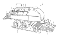
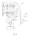
- FIG. 1 is a perspective view of a baler, having a rotatable plunger in accordance with one implementation of the present disclosure.
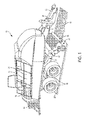
- FIG. 2 is a schematic view of the baler of FIG. 1 illustrating a compression assembly, a pickup assembly, and a controller.
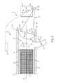
- FIG. 3 is a perspective view of the compression assembly of the baler of FIG. 1 .
- FIG. 4 is a side view of the compression assembly of the baler of FIG. 1 .
- FIG. 5 is a schematic view of the hydraulic assembly of the baler of FIG. 1 .
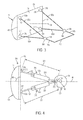
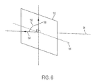
- FIG. 6 is a perspective view of the compression plane of the baler of FIG. 1 .
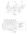
- FIG. 7 illustrates various stages of a first stroke profile of the baler of FIG. 1 .
- FIG. 8 illustrates the compression surface of the baler of FIG. 1 in different vertical compression angles.
- FIG. 9 is a chart correlating the connecting rod lengths for a given crank position with respect to the first stroke profile.
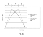
- FIG. 9A is a chart correlating the connecting rod lengths for a given crank position with respect to a second stroke profile.
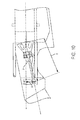
- FIG. 10 illustrates a baler with a fixed-length connecting arm.
- the disclosure relates to a baler, and more particularly to baler having a plunger with a compression surface whose angle with respect to the baler chamber can be altered during the compression process.
- the baler includes a plurality of variable-length connecting rods that permit the angular orientation of the compression surface to be adjusted. By doing so, the baler can achieve larger bale densities while limiting the forces experienced by the gearbox of the baler.
- the variable-length connecting rods permit the baler to achieve greater compression surface angle deviations than that possible with a fixed length connector arm. Still further, the variable-length connecting rods permit the baler to finely tune the reciprocating motion of the plunger, or plunger stroke, with respect to the baling chamber.
- a baler 10 includes a frame 14 , a set of wheels 18 mounted on the frame 14 , a feed system 22 coupled to the frame 14 , a compression system 26 having a plunger assembly 82 ( FIG. 2 ) to receive and compress crop material 54 provided by the feed system 22 , and a controller 38 to monitor and direct the baling operation.
- the baler 10 is a square baler for forming bales 42 of a crop, such as hay, straw, or other biomasses.
- the frame 14 of the baler 10 includes a tow bar 46 extending from the frame 14 and connectable to a towing vehicle (not shown), such as an agricultural tractor or other vehicle.
- the baler 10 also includes a power takeoff shaft 50 connectable to the towing vehicle to transmit a rotating drive force from the towing vehicle to various components of the baler 10 .
- the baler 10 may have a dedicated power supply and/or prime mover (not shown), such as an engine, motor, battery, fuel cell, etc., for driving the wheels 18 and for driving and/or powering the various components of the baler 10 .
- the feed system 22 of the baler 10 is configured to pick up crop material 54 from a support surface 58 and convey it to the compression system 26 .
- the feed system 22 includes a pickup assembly 62 for receiving the crop material 54 from the support surface 58 , and a delivery assembly 64 for directing the collected crop material 54 to the compression system 26 .
- the pickup assembly 62 includes a roller baffle 66 oriented generally perpendicular to the direction of travel for picking up the crop material 54 and placing it in the baler 10 .
- the delivery assembly 64 of the feed system 22 directs the crop material 54 collected by the pickup assembly 62 to the compression system 26 .
- the delivery assembly 64 is configured to direct a metered amount of crop material 54 into the baling chamber 70 during every stroke of the plunger 74 (described below).
- the delivery assembly 64 is adjustable, permitting different amounts of crop material 54 to be fed into the compression system 26 at a given time (i.e., the “feed rate”).
- the feed system 22 is configured to receive one or more signals from the controller 38 causing it to increase or decrease the amount of crop material 54 being delivered to the compression system 26 on a particular stroke.
- the compression system 26 of the baler 10 includes the baling chamber 70 in communication with the feed system 22 , a bale case 78 at least partially defining the baling chamber 70 , and the plunger assembly 82 positioned at least partially within the baling chamber 70 .
- a metered amount of crop material or flake 54 is positioned within the baling chamber 70 by the feed system 22 whereby the plunger assembly 82 compresses the crop material 54 against already compacted crop material positioned in the bale case 78 , herein referred to as the forming bale 86 .
- the plunger assembly 82 then retracts through the baling chamber 70 as another metered amount of crop material 54 is positioned within the baling chamber 70 by the feed system 22 and the stroke begins again.
- the compression system 26 compresses the newly introduced crop material 54 against the face of the forming bale 86 , causing the forming bale 86 to grow into a densely packed cuboid shape within the bale case 78 .
- the forming bale 86 achieves the desired size and density, it is bound (e.g., by wire) to form the bale 42 .
- the freshly created bale 42 subsequently becomes a support surface against which the next forming bale 86 may begin to form and the process is repeated.
- the bale 42 is ejected from the rear of the baler 10 for subsequent collection.
- the bale case 78 is substantially rectangular in shape having a first open end 90 to receive the plunger 74 therein, and a second open end 94 , opposite the first open end 90 positioned proximate the rear of the baler 10 .
- the bale case 78 also defines an axis 96 extending along the length of the bale case 78 proximate its center.
- the bale case 78 acts as a container, holding the forming bale 86 and one or more completed bales 42 against which the compression system 26 compresses the newly introduced crop material 54 from the feed system 22 .
- the bale case 78 applies a compressive or otherwise resistive force against the forming bale 86 and any completed bales 42 to resist motion within the bale case 78 toward the second open end 94 .
- this resistive force permits the compressive force of the compression system 26 to compact the crop material 54 within the baling chamber 70 .
- the bale case 78 includes a top wall 100 , a bottom wall 104 opposite the top wall 100 , and a pair of side walls (not shown) extending between the top wall 100 and the bottom wall 104 . Together, the walls 100 , 104 of the bale case 78 produce a substantially square interior cross-section when taken perpendicular to the axis 96 .
- the walls 100 , 104 of the bale case 78 are adjustable with respect to one another to vary the amount of resistive force applied to the forming bale 86 and bales 42 .
- the walls 100 , 104 of the bale case 78 may move inwardly to apply more pressure to the outside of the forming bale 86 or bale 42 and therefore create a greater resistive force.
- the walls 100 , 104 of the bale case 78 may also move outwardly, away from one another, to reduce the pressure on the outside of the forming bale 86 or bale 42 and therefore create less resistive force.
- the greater the resistive force applied to the forming bale 86 and bales 42 the greater the amount of compression that occurs with each stroke of the compression system 26 and the denser the resulting bale 42 .
- the plunger assembly 82 of the compression system 26 includes a gearbox 108 having an output shaft 112 , a pair of crank arms 116 a , 116 b coupled to and rotatable with the output shaft 112 , the plunger 74 movable with respect to the baling chamber 70 , and a plurality of variable-length connecting rods 120 ( 120 a - d ) each extending between and coupled to both a respective crank arm 116 a ,b and the plunger 74 .
- the plunger assembly 82 also includes a hydraulic system 126 ( FIG. 5 ) to at least partially control the length of the connecting rods 120 a - d (i.e., the connector length 220 , described below).
- the gearbox 108 of the plunger assembly 82 receives input from the power takeoff shaft 50 , which in turn is driven by an exterior source, such as a tractor and the like (described above).
- the gearbox 108 may be driven by a stand-alone power system, such as an internal combustion engine.
- the gearbox 108 typically includes a number of gear sets (not shown) to transmit the torque provided by the power takeoff shaft 50 to the output shaft 112 at a given gear ratio.
- the gearbox 108 may have multiple, interchangeable gear sets to permit the gear ratio provided by the gearbox 108 to be changed according to current operating conditions.
- the plunger 74 of the plunger assembly 82 includes a compression surface 128 configured to engage flake 54 positioned within the baling chamber 70 , and a plurality of plunger mounting points 132 a , 132 b , 132 c , 132 d each coupled to a corresponding connecting rod 120 .
- the compression surface 128 of the plunger 74 includes an upper edge 136 positioned proximate the upper wall 100 of the baling chamber 70 , a lower edge 140 opposite the upper edge 136 and positioned proximate the bottom wall 104 of the baling chamber 70 , a right edge 144 extending between the upper edge 136 and the lower edge 140 , and a left edge 148 opposite the right edge 144 . ( FIG. 3 ).
- the compression surface 128 of the plunger 74 is arcuate or convex in contour having a substantially similar cross-sectional shape along its entire horizontal width (i.e., semi-cylindrical).
- the compression surface 128 may include any planar or curvilinear shape (not shown).
- the compression surface 128 may change in cross-sectional shape along its width as well as along its height (i.e., hemispherical in shape, and the like).
- the plunger 74 also defines a compression plane 152 extending substantially parallel to a rear face of the plunger 74 and fixed with respect to the compression surface 128 .
- the rear face of the plunger 74 may be defined by the plunger mounting points 132 or rod mounting points 212 .
- rotational movement of the compression plate 152 about an axis of rotation 160 forms a compression angle 156 with the axis 96 of the baling chamber 70 .
- the compression angle 156 is defined as the angle formed between a first ray 164 , originating at the intersection of the compression plane 152 and the axis 96 and extending along the axis 96 in a direction opposite the output shaft 112 , and a second ray 168 , originating at the intersection of the compression plane 152 and the axis 96 and extending along the compression plane 152 substantially perpendicular to the axis of rotation 160 (see FIG. 6 ).
- any angular movement of the compression plane 152 with respect to the axis 96 causes the compression angle 152 to change.
- the four plunger mounting points 132 a , 132 b , 132 c , 132 d are generally positioned proximate the corners of the compression surface 128 and co-planar the compression plane 152 . More specifically, the plunger 74 includes the first plunger mounting point 132 a positioned proximate the upper and left edges 136 , 148 of the compression surface 128 , a second plunger mounting point 132 b positioned proximate the upper and right edges 136 , 144 of the compression surface 128 , a third plunger mounting point 132 c positioned proximate the lower and left edges 140 , 148 of the compression surface 128 , and a fourth plunger mounting point 132 d positioned proximate the lower and right edges 140 , 144 of the compression surface 128 . ( FIG. 3 ). While the illustrated implementation includes four plunger mounting points, it is understood that more or fewer plunger mounting points may be present as necessary to compensate for the number of connecting rods 120 present in the
- the plunger 74 is positioned within and movable with respect to the baling chamber 70 both linearly along the axis 96 of the baling chamber 70 and angularly with respect to the axis 96 .
- the angular motion of the plunger 74 may be independently controlled with respect to the linear motion of the plunger 74 .
- the plunger 74 translates or moves linearly along the axis 96 of the baling chamber 70 between an extended position (see Position C of FIG. 7 ), where the plunger 74 is its furthest distance from the output shaft 112 , and a retracted position (see Position A of FIG. 7 ), where the plunger 74 is positioned its closest distance to the output shaft 112 .
- the distance between the retracted position and the extended position is defined as the “plunger stroke length 172 .”
- the plunger stroke length 172 is at least partially determined by the crank throw length 176 (described below) and the connector throw length (described below). During the baling process, the plunger stroke length 172 at least partially determines the density of the resulting bale 42 . In the illustrated implementation, the plunger stroke length 172 is greater than the crank throw length 176 and greater than the connector throw length.
- the plunger 74 In addition to moving linearly along the axis 96 of the baling chamber 70 , the plunger 74 also moves angularly with respect to the axis 96 of the baling chamber 70 during the baling process. In the illustrated implementation, the plunger 74 rotates about an axis of rotation 168 between a first position (see Position B of FIG. 7 ), where the compression plane 152 creates a first compression angle 156 a , and a second position (see Position D of FIG. 7 ), where the compression plane 152 creates a second compression angle 156 b that is larger than the first compression angle 156 a . In the illustrated implementation, the angular difference between the first compression angle 156 a and the second compression angle 156 b is referred to as the “compression arc range.”
- While the illustrated implementation includes a convex compression surface 128 being pivoted about a substantially horizontal axis of rotation 160 , it is understood that in alternative implementations different shaped compression surfaces may be pivoted about one or more axes of rotation 160 , each of which may be in a different relative orientation.
- Each crank arm 116 of the plunger assembly 82 is substantially elongated in shape and transfers torque between the output shaft 112 and one or more connecting rods 120 .
- each crank arm 116 defines a first crank mounting point 192 and a second crank mounting point 196 spaced a crank length 200 from the first crank mounting point 192 .
- the first crank mounting point 192 is coupled to and rotates together with the output shaft 112 of the gearbox 108 while the second crank mounting point 196 is coupled to a respective connecting rod 120 and travels around the first crank mounting point 192 in a substantially circular path.
- the first crank mounting point 192 includes an aperture formed into the crank arm 116 and sized to at least partially receive a portion of the output shaft 112 therein.
- each crank arm 116 defines a crank throw length 176 equal to twice the respective crank length 200 .
- the plunger assembly 82 includes four variable-length connecting rods 120 a , 120 b , 120 c , 120 d , each extending between and coupled to a corresponding crank arm 116 and the plunger 74 .
- the plunger assembly 82 includes a first connecting rod 120 a extending between the first crank arm 116 a and the first plunger mounting point 132 a , a second connecting rod 120 b extending between the second crank arm 116 b and the second plunger mounting point 132 b , a third connecting rod 120 c extending between the first crank arm 116 a and the third plunger mounting point 132 c , and a fourth connecting rod 120 d extending between the second crank arm 116 b and the fourth plunger mounting point 132 d .
- altering the connector length 220 of the first and third connecting rods 120 a , 120 c with respect to the connector length 220 of the second and fourth connecting rods 120 b , 120 d forces the compression plane 152 to rotate about a substantially vertical axis of rotation 160 .
- a combination of the above described motions forces the compression plane 152 to rotate about an axis of rotation 160 that is neither horizontally or vertically oriented.
- altering the relative speed of the different extensions and contractions may cause the axis of rotation 160 to change orientation during operation of the device 10 .
- each variable-length connecting rod 120 of the plunger assembly 82 is substantially elongated in shape having a first rod mounting point 208 , and a second rod mounting point 212 spaced a connector length 220 from the first rod mounting point 208 and movable with respect thereto. More specifically, the first rod mounting point 208 is movable with respect to the second rod mounting point 212 between an extended position (see Position B of FIG. 7 ), where the connector length 220 is a first length, and a retracted position (see Position A of FIG. 7 ), where the connector length 220 is a second length, less than the first length.
- the difference between the first length (i.e., fully extended) and the second length (i.e., fully retracted) is defined as the connector throw length.
- each connecting rod 120 includes an actuator 224 in the form of a hydraulic cylinder coupled to and extending between the second crank mounting point 196 of the respective crank arm 116 and a respective plunger mounting point 132 of the plunger 74 (described above).
- Each actuator 224 includes a cylinder portion 228 and a piston portion 232 moveable with respect to the cylinder portion 228 . ( FIG. 5 ). While the illustrated actuator 224 is a hydraulic cylinder, in alternative implementations the actuator 224 may include a mechanical or pneumatic actuator (not shown).
- the cylinder portion 228 of each actuator 224 is substantially cylindrical in shape including an annular outer wall 234 that at least partially defines an elongated cavity 236 therein.
- the cavity 236 includes a first end 240 proximate the first rod mounting point 208 , and a second end 244 opposite the first end 240 .
- the cylinder portion 228 also includes a first fluid port 248 in fluid communication with the cavity 236 and positioned proximate the first end 240 thereof.
- the cylinder portion 228 also includes a second fluid port 252 in fluid communication with the cavity 236 and positioned proximate the second end 244 thereof.
- the piston portion 232 of the actuator 224 includes a piston 256 sized to be positioned within and movable axially along the length of the cavity 236 of the cylinder portion 228 between the first end 240 and the second end 244 .
- the piston portion 232 also includes a rod 260 extending axially from the piston 256 , beyond the second end 244 of the cavity 236 , to produce the second rod mounting point 212 .
- the piston 256 of the piston portion 232 contacts and forms a seal with the annular outer wall 234 of the cavity 236 thereby dividing the cavity 236 into a first volume 264 in fluid communication with the first fluid port 248 , and a second volume 268 in fluid communication with the second fluid port 252 .
- each actuator 224 receives hydraulic fluid from the hydraulic system 126 causing the piston portion 232 and the second rod mounting point 212 to move with respect to the cylinder portion 228 and the first rod mounting point 208 . More specifically, when the actuator 224 receives hydraulic fluid via the first fluid port 248 , fluid flows into the first volume 264 of the cavity 236 causing the first volume 264 to increase in size while fluid is forced out of the second volume 268 causing the second volume 268 to decrease in size. The resulting fluid flow forces the piston 256 toward the second end 244 of the cavity 236 (see Positions A-C of FIG. 7 ) causing the connector length 220 to increase.
- each connecting rod 120 may include linkages, tracks, pulleys, cables, and gearsets, in addition to the actuator 224 (not shown).
- the hydraulic system 126 of the plunger assembly 82 includes a pump 272 and a reservoir 276 in fluid communication with the pump 272 .
- the hydraulic system 126 also includes a manifold 280 in fluid communication with the pump 272 and configured to direct fluid flow. More specifically, the manifold 280 includes a plurality of valves (not shown) able to direct fluid discharged by the pump 272 to one or more of the connecting rods 120 .
- the pump 272 is a variable displacement pump able to adjust the rate and pressure at which fluid is discharged.
- the hydraulic system 126 may also include one or more safety valves (not shown) to direct excess fluid to the reservoir 276 .
- the hydraulic system 126 includes a single pump configured to selectively provide hydraulic fluid to each of the individual connecting rods 120
- the hydraulic system may include a plurality of pumps, each configured to provide hydraulic fluid to a select group of one or more connecting rods 120 .
- the hydraulic system 126 For each connecting rod 120 , the hydraulic system 126 includes a first feed line 284 extending between and in fluid communication with the manifold 280 and the first fluid port 248 of a respective connecting rod 120 , and a second feed line 288 extending between and in fluid communication with the manifold 280 and the second fluid port 252 of the same connecting rod 120 .
- the manifold 280 also includes one or more valves (not shown) to direct the output of the pump 272 through either the first feed line 284 and/or the second feed line 288 .
- the hydraulic system 126 is able to independently extend and contract any combination of connecting rods 120 during the baling process.
- the controller 38 of the baler 10 includes a processor 292 , a memory unit 296 in operable communication with the processor 292 , one or more sensors 300 , 304 , 308 sending and receiving signals from the processor 292 , and a user input 312 in operable communication with the processor 292 .
- the processor 292 is also in operable communication with various elements of the hydraulic system 126 including, but not limited to, the pump 272 and the manifold 280 , or more precisely the valves associated with the manifold 280 .
- the processor 292 receives signals from the one or more sensors 300 , 304 , 308 , combines that information with one or more predetermined control algorithms, and outputs signals to control the motion and compression angles 156 , 164 of the plunger 74 through the actuators 224 .
- the baler 10 includes a crank arm position sensor 300 , a plunger position sensor 304 , and a plurality of connector length sensors 308 .
- the sensors 300 , 304 , 308 may be present individually, in plurality, or in combination.
- the controller 38 may also include additional sensors such as, but not limited to, a connector length sensor (not shown).
- the crank arm position sensor 300 includes a position sensor mounted to a respective crank arm 116 of the plunger assembly 82 and configured to measure the relative rotational position of the crank arm 116 with respect to the gearbox 108 or “crank position.”
- the crank arm position sensor 300 may include a sensor mounted directly to the crank arm 116 , or a sensor mounted on the output shaft 112 . Such sensors may include Hall Effect sensors, variable resistance sensors, optical sensors, and the like.
- the crank position is defined as an axis extending radially outwardly from the first crank mounting point 192 through the second crank mounting point 196 .
- the 3 o'clock crank position (Position A of FIG. 7 ) generally corresponds with the retracted position of the plunger 74 while the 9 o'clock crank position (Position C of FIG. 7 ) generally corresponds with the extended position of the plunger 74 .
- the plunger position sensor 304 determines the relative position of the plunger 74 with respect to the baling chamber 70 .
- the plunger position sensor 304 may include a sensor mounted directly on the plunger 74 , a sensor mounted to the baling chamber 70 , or a sensor mounted to the output shaft 112 of the gearbox 108 .
- Such sensors may include Hall Effect sensors, variable resistance sensors, optical sensors, and the like.
- Each one of the plurality of connector length sensors 308 determines the connector length 220 of a respective connecting rod 120 .
- Each connector length sensor 308 may include a sensor mounted directly on the respective connecting rod 120 .
- Such sensors may include an optical sensor, a variable resistance sensor, and the like.
- the plunger 74 is configured to compress crop material 54 located within the baling chamber 70 and positioned between the compression surface 128 and the forming bale 86 .
- the plunger 74 begins each stroke from the retracted position (see Position A of FIG. 7 ), with the compression plane 152 substantially normal to the axis 96 of the baling chamber 70 , and with a metered amount of crop material or flake 54 positioned within the baling chamber 70 .
- the plunger 74 then begins moving along the axis 96 toward the extended position while simultaneously rotating in a counter-clockwise direction (with respect to FIG.
- the angled compression surface 128 captures the newly introduced crop material 54 between itself and the forming bale 86 creating a “perpendicular contact point 188 ” on the compression surface 128 (see Position A of FIG. 8 ).
- the perpendicular contact point 188 is the area or region of the compression surface 128 that is both in contact with the forming bale 86 and perpendicular to the axis 96 of the baling chamber 70 .
- the perpendicular contact point 188 is a narrow band extending horizontally across the compression surface 128 .
- the plunger 74 continues to move toward the extended position thereby compressing the crop material 54 into the forming bale 86 .
- the plunger 74 (and compression plane 152 ) beings to rotate about the axis of rotation 160 in a clockwise direction from the first position (see Position B of FIG. 7 ) towards the second position (see Position D of FIG. 7 ). While doing so, the perpendicular contact point 188 begins to travel down the compression surface 128 from a position closer to the upper edge 136 (i.e., when the compression plane 152 is proximate the first position; see Position A of FIG.
- the plunger 74 After undergoing the compression process, the plunger 74 returns back to the retracted position (see Position A of FIG. 7 ) eventually disengaging from the forming bale 86 and moving away from the bale case 78 . Once the plunger 74 has returned to its initial retracted position, the feed system 22 may position a second metered amount of crop material 54 within the baling chamber 70 and the stroke begins anew.
- the processor 292 of the baler 10 monitors the motion of the plunger 74 and the crank arm 116 and outputs signals to the hydraulic system 126 to control the extension and contraction of the connecting rods 120 to produce the desired plunger motion or “stroke profile.” More specifically, the processor 292 outputs signals to the pump 272 and manifold 280 of the hydraulic system 126 to direct the flow of hydraulic fluid toward either the first fluid port 248 or the second fluid port 252 of each individual connecting rod 120 . As the plunger 74 moves along its stroke path, the processor 292 receives a stream of information in the form of signals from the sensors 300 , 304 , 308 positioned throughout the baler 10 .
- the processor 292 may receive data including, but not limited to, the position of the plunger 74 , the rotational position of the crank arm 116 (i.e., the crank position), the connector length 220 of each individual connecting rod 120 , the pressure of the hydraulic fluid within the hydraulic system 126 , the compression angles 156 , 164 of the compression plane 152 , and the like.
- the processor 292 then compiles the raw information received from the sensors 300 , 304 , 308 and processes it to determine the desired connector length 220 for each individual connecting arm 120 as the stroke progresses.
- Each stroke profile may include various quantities and combinations of different stages or steps to produce the desired plunger 74 movement.
- each stroke profile may include an extension stage 322 , a first rotation stage 326 , a second rotation stage 330 , a third rotation stage 334 , a fourth rotation stage 338 , and a retraction stage 342 .
- the timing, frequency, and duration of the various stages are generally dependent upon the relative location of the crank arm 116 or “crank position.” However, in alternative implementations, the timing, frequency, and duration of the various stages may also be dependent upon the position of the plunger 74 , the forces exerted on the plunger 74 , the connector length 220 , the hydraulic fluid pressure levels, and the like.
- a first stroke profile begins with the crank arm 116 in the 3 o'clock crank position, the plunger 74 in the retracted position, and the compression plane 152 substantially normal to the axis 96 .
- both crank arms 116 a ,b travel in a counter-clockwise direction at a relatively constant rotational speed.
- the rotational speed and direction of an individual crank arm 116 a,b may be adjusted as necessary.
- the stroke begins with the extension stage 322 and with the crank arm 116 in the 3 o'clock position.
- the processor 292 sends signals to the hydraulic system 126 instructing the manifold 280 and pump 272 to direct hydraulic fluid via the first feed lines 284 to the first fluid ports 248 of all four connecting rods 120 a , 120 b . 120 c , 120 d .
- this causes the connector length 220 of each connecting rod 120 a , 120 b . 120 c , 120 d to increase.
- the resulting change in connector lengths 220 causes the distance between the second crank mounting point 196 and the plunger 74 to increase but does not contribute to any rotation of the compression plane 152 with respect to the axis 96 of the baling chamber 70 .
- the connector lengths 220 of all four connecting rods 120 a , 120 b . 120 c , 120 d continue to increase throughout the duration of the extension stage 322 ( FIG. 9 ) at a speed generally dictated by the rate at which the pump 272 and manifold 280 provide fluid to the first volumes 264 .
- crank arm 116 is traveling from the 3 o'clock position toward the 2 o'clock position, the rotation of the crank arm 116 causes the plunger 74 to translate toward the extended position while also contributing to the decrease in the vertical compression angle 156 of the compression plane 152 .
- the extension stage 322 continues until the crank arm 116 reaches the 2 o'clock position ( FIG. 9 ). In alternative implementations, the extension stage 322 lasts until the crank arm 116 reaches between approximately the 2 o'clock position and approximately the 12 o'clock position. In still other implementations, the processor 292 may remain in the extension stage 322 until the connector length 220 of each connecting rod 120 a , 120 b . 120 c , 120 d reaches a predetermined value. In still other implementations, the processor 292 may remain in the extension stage until the plunger 74 reaches a predetermined location. In still other implementations, the processor 292 may remain in the extension stage 322 until the plunger 74 reaches a predetermined vertical compression angle 156 . In still other implementations, the duration of the extension stage 322 may take into consideration a combination of the factors listed above.
- the processor 292 After the extension stage 322 , the processor 292 enters the first rotation stage 326 ( FIG. 9 ). During the first rotation stage 326 , the processor 292 sends signals to the hydraulic system 126 instructing the manifold 280 to direct hydraulic fluid via the first feed lines 284 to the first fluid ports 248 of only the first and second connecting rods 120 a , 120 b . The processor 292 also sends signals to the manifold 280 stopping the flow of fluid to the third and fourth connecting rods 120 c , 120 d . The resulting distribution of hydraulic fluid causes the connector lengths 220 of the first and second connecting rods 120 a , 120 b to increase while the connector lengths 220 of the third and fourth connecting rods 120 c , 120 d remains constant.
- the resulting change in connector length 220 causes the vertical compression angle 156 of the compression plane 152 to decrease.
- the connector lengths 220 of the first and second connecting rods 120 a , 120 b continue to increase throughout the duration of the first rotation stage 326 ( FIG. 9 ) at a speed generally dictated by the rate at which the pump 272 is providing fluid to the first volumes 264 .
- the vertical compression angle 156 continues to decrease. Because the crank arm 116 is traveling from the 2 o'clock position toward the 12 o'clock position, the rotation of the crank arm 116 causes the plunger 74 to translate toward the extended position while also contributing to the increase in the vertical compression angle 156 of the compression plane 152 .
- the first rotation stage 326 continues until the crank arm 116 reaches the 12 o'clock position.
- the duration of the first rotation stage 326 may take into consideration a combination of the factors such as those described above (i.e., with respect to the extension stage 322 ).
- the processor 292 After the first rotation stage 326 , the processor 292 enters the second rotation stage 330 ( FIG. 9 ). During the second rotation stage 330 , the processor 292 sends signals to the hydraulic system 126 instructing the manifold 280 and pump 272 to direct hydraulic fluid via the first feed lines 284 to the first fluid ports 248 of only the third and fourth connecting rods 120 c , 120 d . The processor 292 also sends signals to the hydraulic system 126 instructing the manifold 280 to stop fluid flow to the first and second connecting rods 120 a , 120 b .
- the resulting fluid flow causes the connector lengths 220 of the third and fourth connecting rods 120 c , 120 d to increase while the connector lengths 220 of the first and second connecting rods 120 a , 120 b remain constant.
- the resulting changes in connector lengths 220 cause the vertical compression angle 156 of the compression plane 152 to increase.
- the connector lengths 220 of the third and fourth connecting rods 120 c , 120 d continue to increase throughout the duration of the second rotation stage 338 ( FIG. 9 ) at a speed generally dictated by the rate at which the pump 272 and manifold 280 provides fluid to the first volumes 264 . As such, the vertical compression angle 156 continues to increase.
- crank arm 116 Because the crank arm 116 is traveling from the 12 o'clock position toward the 9 o'clock position, the rotation of the crank arm 116 causes the plunger 74 to travel toward the extended position while also contributing to the increase in the vertical compression angle 156 of the compression plane 152 .
- the second rotation stage 330 continues until the crank arm 116 reaches the 9 o'clock position (see Position C of FIG. 7 ).
- the second rotation stage 330 may take into consideration a combination of factors such as those described above (i.e., with respect to the extension stage 322 ).
- the processor 292 After the second rotation stage 330 , the processor 292 enters the third rotation stage 334 ( FIG. 9 ). During the third rotation stage 334 , the processor 292 sends signals to the hydraulic system 126 instructing the manifold 280 and pump 272 to direct hydraulic fluid via the second feed lines 288 to the second fluid ports 252 of only the first and second connecting rods 120 a , 120 b . The processor 292 also sends signals to the hydraulic system 126 instructing the manifold 280 to stop fluid flow to the third and fourth connecting rods 120 c , 120 d .
- the resulting fluid flow causes the connector lengths 220 of the first and second connecting rods 120 a , 120 b to decrease while the connector lengths 220 of the third and fourth connecting rods 120 c , 120 d remain constant.
- the resulting change in connector lengths cause the vertical compression angle 156 to increase.
- the connector lengths 220 of the first and second connecting rods 120 a , 120 b continue to decrease throughout the duration of the third rotation stage 334 ( FIG. 9 ) at a speed generally dictated by the rate at which the pump 272 provides fluid to the second volumes 268 of the first and second connecting rods 120 a , 120 b .
- the vertical compression angle 156 continues to increase.
- crank arm 116 Because the crank arm 116 travels from 9 o'clock position toward the 6 o'clock position, the rotation of the crank arm 116 causes the plunger 74 to travel away from the extended position (i.e., toward the retracted position) and contributes to the increase in the vertical compression angle 156 of the compression plane 152 .
- the third rotation stage 334 continues until the crank arm 116 reaches the 6 o'clock position.
- the duration of the third rotation stage 334 may take into consideration a combination of different factors such as those described above (i.e., with respect to the extension stage 322 ).
- the processor 292 After the third rotation stage 334 , the processor 292 enters the fourth rotation stage 338 ( FIG. 9 ). During the fourth rotation stage 338 , the processor 292 sends signals to the hydraulic system 126 instructing the manifold 280 and the pump 272 to direct hydraulic fluid via the second feed lines 288 to the second fluid ports 252 of only the third and fourth connecting rods 120 c , 120 d . The processor 292 also sends signals to the hydraulic system 126 instructing the manifold 280 to stop fluid flow to the first and second connecting rods 120 a , 120 b .
- the resulting fluid flow causes the connector lengths 220 of the third and fourth connecting rods 120 c , 120 d to decrease while the connector length 220 of the first and second connecting rods 120 a , 120 b remain constant.
- the resulting change in connector lengths 220 causes the vertical compression angle 156 to decrease.
- the connector lengths 220 of the third and fourth connecting rods 120 c , 120 d continue to decrease throughout the duration of the fourth rotation stage 338 ( FIG. 9 ) at a speed generally dictated by the rate at which the pump 272 is providing fluid to the second volumes 268 . As such, the compression angle 156 continues to decrease.
- crank arm 116 Because the crank arm 116 is traveling from the 6 o'clock position toward the 4 o'clock position, the rotation of the crank arm 116 causes the plunger 74 to travel toward the retracted position while also contributes to the decrease in the vertical compression angle 156 of the compression plane 152 .
- the fourth rotation stage 338 continues until the crank arm 116 reaches the 4 o'clock position (Position A of FIG. 7 ).
- the duration of the fourth rotation stage 338 may take into consideration a combination of the factors such as those described above (i.e., with respect to the extension stage 322 ).
- the processor 292 After the fourth rotation stage 338 , the processor 292 enters the retraction stage 342 . During the retraction stage 342 , the processor 292 sends signals to the hydraulic system 126 instructing the manifold 280 and pump 272 to direct hydraulic fluid via the second feed lines 288 to the second fluid ports 252 of all four connecting rods 120 a , 120 b . 120 c , 120 d . As described above, the resulting fluid flow causes the connector lengths 220 of each connecting rod 120 a , 120 b . 120 c , 120 d to decrease.
- the resulting change in connector lengths 220 causes the distance between the second crank mounting point 196 and the plunger 74 to decrease but does not contribute to any rotation of the compression plane 152 with respect to the axis 96 of the baling chamber 70 .
- the connector lengths 220 of all four connecting rods 120 a , 120 b . 120 c , 120 d continue to decrease throughout the duration of the retraction stage 342 ( FIG. 9 ) at a speed generally dictated by the rate at which the pump 272 is providing fluid to the second volumes 268 .
- crank arm 116 is traveling from the 6 o'clock position toward the 3 o'clock position, the rotation of the crank arm 116 causes the plunger 74 to translate toward the retracted position while also contributing to the increase in the vertical compression angle 156 of the compression plane 152 .
- the processor 292 may enter the extension stage 322 and the cycle begins anew.
- the processor 292 may combine the extension stage 322 with the first rotation stage 326 to create a first combined stage 400 .
- the processor 292 causes the connector lengths 220 of the first and second connecting rods 120 a , 120 b to increasing at a first rate while the connector lengths 220 of the third and fourth connecting rods 120 c , 120 d increase at a second rate slower than the first rate.
- the resulting stage 400 permits both the translational movement of the plunger 74 due to the overall increase of connector lengths 220 of all four connecting rods 120 a , 120 b , 120 c , 120 d while also contributing to the decrease in vertical compression angle 156 by causing the first and second connecting rods 120 a , 120 b to extend longer than the third and fourth connecting rods 120 c , 120 d.
- the processor 292 may then combine the second and third rotation stages 330 , 334 into a second combined stage 404 . ( FIG. 9 a ).
- the processor 292 increases the connector lengths 220 of the third and fourth connecting rods 120 c , 120 d at a first rate while simultaneously decreasing the connector lengths 220 of the first and second connecting rods 120 a , 120 b at the same first rate.
- the above described extensions and contractions result in the compression plane 152 rotating in a clockwise direction from the first position to the second position (described above).
- the processor 292 may also combine the fourth rotation stage 338 and the retraction stage 342 into a third combined stage 408 . ( FIG. 9 a ).
- the processor 292 decreases the connector lengths 220 of the first and second connecting rods 120 a , 120 b at a first rate while decreasing the connector lengths 220 of the third and fourth connecting rods 120 c , 120 d at a second rate that is greater than the first rate.
- the resulting third combined stage 408 permits both the translational movement of the plunger 74 due to the overall decrease in connector lengths 220 of all four connecting rods 120 a , 120 b , 120 c , 120 d while also contributing to the increase in vertical compression angle 156 by allowing the third and fourth connecting rods 120 c , 120 d to shorten by a larger distance than the first and second connecting rods 120 a , 120 b.
- the processor 292 may only utilize the connecting rods 120 a , 120 b , 120 c , 120 d for purely translational motion, relying on the rotation of the crank arm 116 to create the necessary angular movement of the compression plane 152 .
- the layout of the connecting rods 120 a , 120 b , 120 c , 120 d allow the distance between the plunger 74 and the second crank mounting point 196 to be altered while simultaneously fixing the rotational movement of the plunger 74 to the crank arm 116 .
- any changes to the compression angle 156 will be purely the result of the crank arm's rotation during the baling process.
Landscapes
- Life Sciences & Earth Sciences (AREA)
- Environmental Sciences (AREA)
- Transmission Devices (AREA)
- Reciprocating Pumps (AREA)
Abstract
Description
- The present disclosure relates to an agricultural baler having a compression system for forming bales of crop.
- Large square balers have been used for harvesting hay for many years. Their primary advantage over other types of balers is that they densify the crop into large rectangular-shaped bales, which minimizes both shipping and storage costs. Currently, there is a desire to create bales with higher density, which requires higher plunger forces and thus higher loads on the elements of the drive train (i.e., the connecting rod, gearbox, crank arm, and the like). As such, current baler designs require increasingly more expensive components in the drive train to allow for such large plunger forces.
- In one aspect, a baler including a frame, a feed system coupled to the frame, a baling chamber defining an axis therethrough, a crank arm, and a plunger being at least partially positioned within and movable with respect to the baling chamber. Where the plunger includes a compression surface and defines a compression plane fixed with respect to the compression surface, where the compression plane defines a compression angle with respect to the axis of the baling chamber, and wherein the compression angle is adjustable independently of the rotation of the crank arm.
- In another aspect, a baler including a frame, a feed system coupled to the frame, a baling chamber defining an axis therethrough, a crank arm defining a crank throw length, and a plunger positioned within and moveable with respect to the baling chamber. Where the plunger includes a compression surface and defines a compression plane fixed with respect to the compression surface, where the compression plane defines a compression angle with respect to the axis of the baling chamber, where the compression angle is adjustable, where the plunger defines a plunger stroke length, and wherein the plunger stroke length is greater than the crank throw length.
- In still another aspect, a baler including a frame, a feed system coupled to the frame, a baling chamber defining an axis therethrough, a crank arm having a first crank mounting point, a plunger positioned within and moveable with respect to the baling chamber, the plunger having a compression surface and defining a compression plane fixed with respect to the compression surface, where the compression plane defines a compression angle with respect to the axis of the baling chamber, and wherein the compression angle is adjustable. The baler also including a first connecting arm extending between and coupled to the plunger closer to a top edge of the compression surface than a bottom edge of the compression surface and the crank arm at the first crank mounting point, and a second connecting arm extending between and coupled to the plunger closer to the bottom edge of the compression surface than the top edge of the compression surface and the crank arm at the first crank mounting point.
- Other aspects of the disclosure will become apparent by consideration of the detailed description and accompanying drawings.
-
FIG. 1 is a perspective view of a baler, having a rotatable plunger in accordance with one implementation of the present disclosure. -
FIG. 2 is a schematic view of the baler ofFIG. 1 illustrating a compression assembly, a pickup assembly, and a controller. -
FIG. 3 is a perspective view of the compression assembly of the baler ofFIG. 1 . -
FIG. 4 is a side view of the compression assembly of the baler ofFIG. 1 . -
FIG. 5 is a schematic view of the hydraulic assembly of the baler ofFIG. 1 . -
FIG. 6 is a perspective view of the compression plane of the baler ofFIG. 1 . -
FIG. 7 illustrates various stages of a first stroke profile of the baler ofFIG. 1 . -
FIG. 8 illustrates the compression surface of the baler ofFIG. 1 in different vertical compression angles. -
FIG. 9 is a chart correlating the connecting rod lengths for a given crank position with respect to the first stroke profile. -
FIG. 9A is a chart correlating the connecting rod lengths for a given crank position with respect to a second stroke profile. -
FIG. 10 illustrates a baler with a fixed-length connecting arm. - Before any embodiments of the disclosure are explained in detail, it is to be understood that the disclosure is not limited in its application to the details of the formation and arrangement of components set forth in the following description or illustrated in the accompanying drawings. The disclosure is capable of supporting other implementations and of being practiced or of being carried out in various ways.
- The disclosure relates to a baler, and more particularly to baler having a plunger with a compression surface whose angle with respect to the baler chamber can be altered during the compression process. More specifically, the baler includes a plurality of variable-length connecting rods that permit the angular orientation of the compression surface to be adjusted. By doing so, the baler can achieve larger bale densities while limiting the forces experienced by the gearbox of the baler. Furthermore, the variable-length connecting rods permit the baler to achieve greater compression surface angle deviations than that possible with a fixed length connector arm. Still further, the variable-length connecting rods permit the baler to finely tune the reciprocating motion of the plunger, or plunger stroke, with respect to the baling chamber.
- Referring to
FIG. 1 , abaler 10 includes aframe 14, a set ofwheels 18 mounted on theframe 14, afeed system 22 coupled to theframe 14, acompression system 26 having a plunger assembly 82 (FIG. 2 ) to receive and compresscrop material 54 provided by thefeed system 22, and acontroller 38 to monitor and direct the baling operation. In the illustrated implementation, thebaler 10 is a square baler for formingbales 42 of a crop, such as hay, straw, or other biomasses. - In the illustrated embodiment, the
frame 14 of thebaler 10 includes atow bar 46 extending from theframe 14 and connectable to a towing vehicle (not shown), such as an agricultural tractor or other vehicle. Thebaler 10 also includes apower takeoff shaft 50 connectable to the towing vehicle to transmit a rotating drive force from the towing vehicle to various components of thebaler 10. In other implementations, thebaler 10 may have a dedicated power supply and/or prime mover (not shown), such as an engine, motor, battery, fuel cell, etc., for driving thewheels 18 and for driving and/or powering the various components of thebaler 10. - As shown in
FIGS. 1 and 2 , thefeed system 22 of thebaler 10 is configured to pick upcrop material 54 from asupport surface 58 and convey it to thecompression system 26. In the illustrated implementation, thefeed system 22 includes apickup assembly 62 for receiving thecrop material 54 from thesupport surface 58, and adelivery assembly 64 for directing the collectedcrop material 54 to thecompression system 26. Thepickup assembly 62 includes aroller baffle 66 oriented generally perpendicular to the direction of travel for picking up thecrop material 54 and placing it in thebaler 10. - The
delivery assembly 64 of thefeed system 22 directs thecrop material 54 collected by thepickup assembly 62 to thecompression system 26. In particular, thedelivery assembly 64 is configured to direct a metered amount ofcrop material 54 into thebaling chamber 70 during every stroke of the plunger 74 (described below). In the illustrated implementation, thedelivery assembly 64 is adjustable, permitting different amounts ofcrop material 54 to be fed into thecompression system 26 at a given time (i.e., the “feed rate”). In particular, thefeed system 22 is configured to receive one or more signals from thecontroller 38 causing it to increase or decrease the amount ofcrop material 54 being delivered to thecompression system 26 on a particular stroke. - Illustrated in
FIG. 2 , thecompression system 26 of thebaler 10 includes thebaling chamber 70 in communication with thefeed system 22, abale case 78 at least partially defining thebaling chamber 70, and theplunger assembly 82 positioned at least partially within thebaling chamber 70. During operation, a metered amount of crop material orflake 54 is positioned within thebaling chamber 70 by thefeed system 22 whereby theplunger assembly 82 compresses thecrop material 54 against already compacted crop material positioned in thebale case 78, herein referred to as the formingbale 86. Theplunger assembly 82 then retracts through thebaling chamber 70 as another metered amount ofcrop material 54 is positioned within thebaling chamber 70 by thefeed system 22 and the stroke begins again. With each passing stroke, thecompression system 26 compresses the newly introducedcrop material 54 against the face of the formingbale 86, causing the formingbale 86 to grow into a densely packed cuboid shape within thebale case 78. Once the formingbale 86 achieves the desired size and density, it is bound (e.g., by wire) to form thebale 42. The freshly createdbale 42 subsequently becomes a support surface against which the next formingbale 86 may begin to form and the process is repeated. Once abale 42 is completely formed, thebale 42 is ejected from the rear of thebaler 10 for subsequent collection. - The
bale case 78 is substantially rectangular in shape having a firstopen end 90 to receive theplunger 74 therein, and a secondopen end 94, opposite the firstopen end 90 positioned proximate the rear of thebaler 10. Thebale case 78 also defines anaxis 96 extending along the length of thebale case 78 proximate its center. During use, thebale case 78 acts as a container, holding the formingbale 86 and one or more completedbales 42 against which thecompression system 26 compresses the newly introducedcrop material 54 from thefeed system 22. While doing so, thebale case 78 applies a compressive or otherwise resistive force against the formingbale 86 and any completedbales 42 to resist motion within thebale case 78 toward the secondopen end 94. In particular, it is this resistive force that permits the compressive force of thecompression system 26 to compact thecrop material 54 within thebaling chamber 70. - In the illustrated implementation, the
bale case 78 includes atop wall 100, abottom wall 104 opposite thetop wall 100, and a pair of side walls (not shown) extending between thetop wall 100 and thebottom wall 104. Together, thewalls bale case 78 produce a substantially square interior cross-section when taken perpendicular to theaxis 96. - The
walls bale case 78 are adjustable with respect to one another to vary the amount of resistive force applied to the formingbale 86 andbales 42. Specifically, thewalls bale case 78 may move inwardly to apply more pressure to the outside of the formingbale 86 orbale 42 and therefore create a greater resistive force. Thewalls bale case 78 may also move outwardly, away from one another, to reduce the pressure on the outside of the formingbale 86 orbale 42 and therefore create less resistive force. Generally speaking, the greater the resistive force applied to the formingbale 86 andbales 42, the greater the amount of compression that occurs with each stroke of thecompression system 26 and the denser the resultingbale 42. - Referring now to
FIGS. 2-4 , theplunger assembly 82 of thecompression system 26 includes agearbox 108 having anoutput shaft 112, a pair of crankarms output shaft 112, theplunger 74 movable with respect to the balingchamber 70, and a plurality of variable-length connecting rods 120 (120 a-d) each extending between and coupled to both arespective crank arm 116 a,b and theplunger 74. Theplunger assembly 82 also includes a hydraulic system 126 (FIG. 5 ) to at least partially control the length of the connecting rods 120 a-d (i.e., theconnector length 220, described below). In the illustrated embodiment, thegearbox 108 of theplunger assembly 82 receives input from thepower takeoff shaft 50, which in turn is driven by an exterior source, such as a tractor and the like (described above). In alternative implementations, thegearbox 108 may be driven by a stand-alone power system, such as an internal combustion engine. Thegearbox 108 typically includes a number of gear sets (not shown) to transmit the torque provided by thepower takeoff shaft 50 to theoutput shaft 112 at a given gear ratio. In some implementations, thegearbox 108 may have multiple, interchangeable gear sets to permit the gear ratio provided by thegearbox 108 to be changed according to current operating conditions. - The
plunger 74 of theplunger assembly 82 includes acompression surface 128 configured to engageflake 54 positioned within the balingchamber 70, and a plurality ofplunger mounting points compression surface 128 of theplunger 74 includes anupper edge 136 positioned proximate theupper wall 100 of the balingchamber 70, alower edge 140 opposite theupper edge 136 and positioned proximate thebottom wall 104 of the balingchamber 70, aright edge 144 extending between theupper edge 136 and thelower edge 140, and aleft edge 148 opposite theright edge 144. (FIG. 3 ). In the illustrated implementation, thecompression surface 128 of theplunger 74 is arcuate or convex in contour having a substantially similar cross-sectional shape along its entire horizontal width (i.e., semi-cylindrical). However, in alternative implementations, thecompression surface 128 may include any planar or curvilinear shape (not shown). In still other implementations, thecompression surface 128 may change in cross-sectional shape along its width as well as along its height (i.e., hemispherical in shape, and the like). - The
plunger 74 also defines acompression plane 152 extending substantially parallel to a rear face of theplunger 74 and fixed with respect to thecompression surface 128. The rear face of theplunger 74 may be defined by the plunger mounting points 132 or rod mounting points 212. During operation, rotational movement of thecompression plate 152 about an axis ofrotation 160 forms acompression angle 156 with theaxis 96 of the baling chamber70. For the purposes of this application, thecompression angle 156 is defined as the angle formed between afirst ray 164, originating at the intersection of thecompression plane 152 and theaxis 96 and extending along theaxis 96 in a direction opposite theoutput shaft 112, and asecond ray 168, originating at the intersection of thecompression plane 152 and theaxis 96 and extending along thecompression plane 152 substantially perpendicular to the axis of rotation 160 (seeFIG. 6 ). As such, any angular movement of thecompression plane 152 with respect to theaxis 96 causes thecompression angle 152 to change. - The four
plunger mounting points compression surface 128 and co-planar thecompression plane 152. More specifically, theplunger 74 includes the firstplunger mounting point 132 a positioned proximate the upper and leftedges compression surface 128, a secondplunger mounting point 132 b positioned proximate the upper andright edges compression surface 128, a thirdplunger mounting point 132 c positioned proximate the lower and leftedges compression surface 128, and a fourthplunger mounting point 132 d positioned proximate the lower andright edges compression surface 128. (FIG. 3 ). While the illustrated implementation includes four plunger mounting points, it is understood that more or fewer plunger mounting points may be present as necessary to compensate for the number of connecting rods 120 present in the device. - During use, the
plunger 74 is positioned within and movable with respect to the balingchamber 70 both linearly along theaxis 96 of the balingchamber 70 and angularly with respect to theaxis 96. In the present implementation, the angular motion of theplunger 74 may be independently controlled with respect to the linear motion of theplunger 74. - With regards to the linear motion, the
plunger 74 translates or moves linearly along theaxis 96 of the balingchamber 70 between an extended position (see Position C ofFIG. 7 ), where theplunger 74 is its furthest distance from theoutput shaft 112, and a retracted position (see Position A ofFIG. 7 ), where theplunger 74 is positioned its closest distance to theoutput shaft 112. For the purposes of this application, the distance between the retracted position and the extended position is defined as the “plunger stroke length 172.” Theplunger stroke length 172 is at least partially determined by the crank throw length 176 (described below) and the connector throw length (described below). During the baling process, theplunger stroke length 172 at least partially determines the density of the resultingbale 42. In the illustrated implementation, theplunger stroke length 172 is greater than thecrank throw length 176 and greater than the connector throw length. - In addition to moving linearly along the
axis 96 of the balingchamber 70, theplunger 74 also moves angularly with respect to theaxis 96 of the balingchamber 70 during the baling process. In the illustrated implementation, theplunger 74 rotates about an axis ofrotation 168 between a first position (see Position B ofFIG. 7 ), where thecompression plane 152 creates afirst compression angle 156 a, and a second position (see Position D ofFIG. 7 ), where thecompression plane 152 creates asecond compression angle 156 b that is larger than thefirst compression angle 156 a. In the illustrated implementation, the angular difference between thefirst compression angle 156 a and thesecond compression angle 156 b is referred to as the “compression arc range.” - While the illustrated implementation includes a
convex compression surface 128 being pivoted about a substantially horizontal axis ofrotation 160, it is understood that in alternative implementations different shaped compression surfaces may be pivoted about one or more axes ofrotation 160, each of which may be in a different relative orientation. - Each crank
arm 116 of theplunger assembly 82 is substantially elongated in shape and transfers torque between theoutput shaft 112 and one or more connecting rods 120. Referring toFIG. 7 , each crankarm 116 defines a firstcrank mounting point 192 and a secondcrank mounting point 196 spaced acrank length 200 from the firstcrank mounting point 192. When assembled, the firstcrank mounting point 192 is coupled to and rotates together with theoutput shaft 112 of thegearbox 108 while the secondcrank mounting point 196 is coupled to a respective connecting rod 120 and travels around the firstcrank mounting point 192 in a substantially circular path. In the illustrated implementation, the firstcrank mounting point 192 includes an aperture formed into thecrank arm 116 and sized to at least partially receive a portion of theoutput shaft 112 therein. In the present application, each crankarm 116 defines acrank throw length 176 equal to twice the respective cranklength 200. - Illustrated in
FIG. 3 , theplunger assembly 82 includes four variable-length connecting rods corresponding crank arm 116 and theplunger 74. More specifically, theplunger assembly 82 includes a first connectingrod 120 a extending between thefirst crank arm 116 a and the firstplunger mounting point 132 a, a second connectingrod 120 b extending between thesecond crank arm 116 b and the secondplunger mounting point 132 b, a third connectingrod 120 c extending between thefirst crank arm 116 a and the thirdplunger mounting point 132 c, and a fourth connectingrod 120 d extending between thesecond crank arm 116 b and the fourthplunger mounting point 132 d. During use, the extension and contraction of various combinations of the connecting rods 120, combined with the rotational motion of thecrank arms 116 causes the compression surface 128 (and the corresponding compression plane 152) to move angularly with respect to theaxis 96 of the balingchamber 70. - For example, increasing the
connector length 220 of the first and second connectingrods connector length 220 of the third and fourth connectingrods compression plane 152 to rotate about a substantially horizontal axis ofrotation 160 in a substantially counter-clockwise direction (as viewed inFIG. 7 ).. In contrast, reducing theconnector length 220 of the first and second connectingrods connector length 220 of the third and fourth connectingrods compression plane 152 to rotate about a substantially horizontal axis ofrotation 160 in a clockwise direction (as viewed inFIG. 7 ). In another example, altering theconnector length 220 of the first and third connectingrods connector length 220 of the second and fourth connectingrods compression plane 152 to rotate about a substantially vertical axis ofrotation 160. Still further, a combination of the above described motions forces thecompression plane 152 to rotate about an axis ofrotation 160 that is neither horizontally or vertically oriented. Further still, altering the relative speed of the different extensions and contractions may cause the axis ofrotation 160 to change orientation during operation of thedevice 10. - Still further, increasing or decreasing the
connector lengths 220 of all fourconnecting rods compression plane 152 and, when viewed independent of the crank rotation, does not change thecompression angle 156. - As described above, the extension and contraction of the connecting
rods FIG. 10 ). For a baler with a fixed-length connecting rod of length B and crank length A, the maximum “fixed arc range” is ±θ degrees when θ=sin−1(A/B). - As illustrated in
FIG. 4 , each variable-length connecting rod 120 of theplunger assembly 82 is substantially elongated in shape having a firstrod mounting point 208, and a secondrod mounting point 212 spaced aconnector length 220 from the firstrod mounting point 208 and movable with respect thereto. More specifically, the firstrod mounting point 208 is movable with respect to the secondrod mounting point 212 between an extended position (see Position B ofFIG. 7 ), where theconnector length 220 is a first length, and a retracted position (see Position A ofFIG. 7 ), where theconnector length 220 is a second length, less than the first length. For the purposes of this application, the difference between the first length (i.e., fully extended) and the second length (i.e., fully retracted) is defined as the connector throw length. - In the illustrated implementation, each connecting rod 120 includes an actuator 224 in the form of a hydraulic cylinder coupled to and extending between the second
crank mounting point 196 of the respective crankarm 116 and a respective plunger mounting point 132 of the plunger 74 (described above). Each actuator 224 includes acylinder portion 228 and apiston portion 232 moveable with respect to thecylinder portion 228. (FIG. 5 ). While the illustrated actuator 224 is a hydraulic cylinder, in alternative implementations the actuator 224 may include a mechanical or pneumatic actuator (not shown). - With reference to
FIG. 5 , thecylinder portion 228 of each actuator 224 is substantially cylindrical in shape including an annularouter wall 234 that at least partially defines anelongated cavity 236 therein. Thecavity 236, in turn, includes afirst end 240 proximate the firstrod mounting point 208, and asecond end 244 opposite thefirst end 240. Thecylinder portion 228 also includes a firstfluid port 248 in fluid communication with thecavity 236 and positioned proximate thefirst end 240 thereof. Thecylinder portion 228 also includes a secondfluid port 252 in fluid communication with thecavity 236 and positioned proximate thesecond end 244 thereof. - As shown in
FIG. 5 , thepiston portion 232 of the actuator 224 includes apiston 256 sized to be positioned within and movable axially along the length of thecavity 236 of thecylinder portion 228 between thefirst end 240 and thesecond end 244. Thepiston portion 232 also includes arod 260 extending axially from thepiston 256, beyond thesecond end 244 of thecavity 236, to produce the secondrod mounting point 212. When the actuator 224 is assembled, thepiston 256 of thepiston portion 232 contacts and forms a seal with the annularouter wall 234 of thecavity 236 thereby dividing thecavity 236 into afirst volume 264 in fluid communication with the firstfluid port 248, and asecond volume 268 in fluid communication with the secondfluid port 252. - During use, each actuator 224 receives hydraulic fluid from the
hydraulic system 126 causing thepiston portion 232 and the secondrod mounting point 212 to move with respect to thecylinder portion 228 and the firstrod mounting point 208. More specifically, when the actuator 224 receives hydraulic fluid via the firstfluid port 248, fluid flows into thefirst volume 264 of thecavity 236 causing thefirst volume 264 to increase in size while fluid is forced out of thesecond volume 268 causing thesecond volume 268 to decrease in size. The resulting fluid flow forces thepiston 256 toward thesecond end 244 of the cavity 236 (see Positions A-C ofFIG. 7 ) causing theconnector length 220 to increase. In contrast, when the actuator 224 receives hydraulic fluid via the secondfluid port 252, fluid flows into thesecond volume 268 of thecavity 236 causing thesecond volume 268 to increase in size while fluid is forced out of thefirst volume 264 causing thefirst volume 264 to decrease in size. The resulting fluid flow forces thepiston 256 toward thefirst end 240 of thecavity 236 and causes theconnector length 220 to decrease. - While the present implementation illustrates the actuator 224 having the
cylinder portion 228 coupled to arespective crank arm 116 and thepiston portion 232 coupled to theplunger 74, it is understood that the actuator 224 may be installed in the opposite orientation (i.e., with thecylinder portion 228 coupled to theplunger 74 and thepiston portion 232 coupled to the crank arm 116). In still other implementations, each connecting rod 120 may include linkages, tracks, pulleys, cables, and gearsets, in addition to the actuator 224 (not shown). - With continued reference to
FIG. 5 , thehydraulic system 126 of theplunger assembly 82 includes apump 272 and areservoir 276 in fluid communication with thepump 272. Thehydraulic system 126 also includes a manifold 280 in fluid communication with thepump 272 and configured to direct fluid flow. More specifically, the manifold 280 includes a plurality of valves (not shown) able to direct fluid discharged by thepump 272 to one or more of the connecting rods 120. In the illustrated implementation, thepump 272 is a variable displacement pump able to adjust the rate and pressure at which fluid is discharged. Although not shown, thehydraulic system 126 may also include one or more safety valves (not shown) to direct excess fluid to thereservoir 276. Furthermore, while the presenthydraulic system 126 includes a single pump configured to selectively provide hydraulic fluid to each of the individual connecting rods 120, in alternative implementations, the hydraulic system may include a plurality of pumps, each configured to provide hydraulic fluid to a select group of one or more connecting rods 120. - For each connecting rod 120, the
hydraulic system 126 includes afirst feed line 284 extending between and in fluid communication with the manifold 280 and the firstfluid port 248 of a respective connecting rod 120, and asecond feed line 288 extending between and in fluid communication with the manifold 280 and the secondfluid port 252 of the same connecting rod 120. The manifold 280 also includes one or more valves (not shown) to direct the output of thepump 272 through either thefirst feed line 284 and/or thesecond feed line 288. As such, thehydraulic system 126 is able to independently extend and contract any combination of connecting rods 120 during the baling process. - Illustrated in
FIGS. 2 and 5 , thecontroller 38 of thebaler 10 includes aprocessor 292, a memory unit 296 in operable communication with theprocessor 292, one ormore sensors processor 292, and auser input 312 in operable communication with theprocessor 292. Theprocessor 292 is also in operable communication with various elements of thehydraulic system 126 including, but not limited to, thepump 272 and the manifold 280, or more precisely the valves associated with themanifold 280. During use, theprocessor 292 receives signals from the one ormore sensors plunger 74 through the actuators 224. - In particular, the
baler 10 includes a crankarm position sensor 300, aplunger position sensor 304, and a plurality ofconnector length sensors 308. Thesensors controller 38 may also include additional sensors such as, but not limited to, a connector length sensor (not shown). - The crank
arm position sensor 300 includes a position sensor mounted to arespective crank arm 116 of theplunger assembly 82 and configured to measure the relative rotational position of thecrank arm 116 with respect to thegearbox 108 or “crank position.” The crankarm position sensor 300 may include a sensor mounted directly to thecrank arm 116, or a sensor mounted on theoutput shaft 112. Such sensors may include Hall Effect sensors, variable resistance sensors, optical sensors, and the like. For the purposes of this application, the crank position is defined as an axis extending radially outwardly from the firstcrank mounting point 192 through the secondcrank mounting point 196. As such, the 3 o'clock crank position (Position A ofFIG. 7 ) generally corresponds with the retracted position of theplunger 74 while the 9 o'clock crank position (Position C ofFIG. 7 ) generally corresponds with the extended position of theplunger 74. - The
plunger position sensor 304 determines the relative position of theplunger 74 with respect to the balingchamber 70. Theplunger position sensor 304 may include a sensor mounted directly on theplunger 74, a sensor mounted to the balingchamber 70, or a sensor mounted to theoutput shaft 112 of thegearbox 108. Such sensors may include Hall Effect sensors, variable resistance sensors, optical sensors, and the like. - Each one of the plurality of
connector length sensors 308 determines theconnector length 220 of a respective connecting rod 120. Eachconnector length sensor 308 may include a sensor mounted directly on the respective connecting rod 120. Such sensors may include an optical sensor, a variable resistance sensor, and the like. - During the baling process, the
plunger 74 is configured to compresscrop material 54 located within the balingchamber 70 and positioned between thecompression surface 128 and the formingbale 86. In particular, theplunger 74 begins each stroke from the retracted position (see Position A ofFIG. 7 ), with thecompression plane 152 substantially normal to theaxis 96 of the balingchamber 70, and with a metered amount of crop material orflake 54 positioned within the balingchamber 70. Theplunger 74 then begins moving along theaxis 96 toward the extended position while simultaneously rotating in a counter-clockwise direction (with respect toFIG. 7 ) toward the first position (i.e., rotating about a substantially horizontal axis of rotation 1 and reducing thecompression angle 156; seeFIG. 7 ). As theplunger 74 approaches the first position (Position B ofFIG. 7 ), theangled compression surface 128 captures the newly introducedcrop material 54 between itself and the formingbale 86 creating a “perpendicular contact point 188” on the compression surface 128 (see Position A ofFIG. 8 ). In the present application, theperpendicular contact point 188 is the area or region of thecompression surface 128 that is both in contact with the formingbale 86 and perpendicular to theaxis 96 of the balingchamber 70. In the present implementation, theperpendicular contact point 188 is a narrow band extending horizontally across thecompression surface 128. - After the
crop material 54 has been captured, theplunger 74 continues to move toward the extended position thereby compressing thecrop material 54 into the formingbale 86. During the compression process, the plunger 74 (and compression plane 152) beings to rotate about the axis ofrotation 160 in a clockwise direction from the first position (see Position B ofFIG. 7 ) towards the second position (see Position D ofFIG. 7 ). While doing so, theperpendicular contact point 188 begins to travel down thecompression surface 128 from a position closer to the upper edge 136 (i.e., when thecompression plane 152 is proximate the first position; see Position A ofFIG. 8 ) to a position closer to the lower edge 140 (i.e., when thecompression plane 152 is proximate the second position; see Positions C ofFIG. 8 ). This rotational movement causes thecompression surface 128 to progressively compress the capturedcrop material 54 from the top down (i.e., from proximate theupper edge 136 to proximate the lower edge 140). More specifically, thecompression surface 128 only compresses thecrop material 54 positioned proximate theperpendicular contact point 188 at any one time. As such, the compressive force required to produce a desired bale density is reduced when compared to a similarly sized non-rotational compressive surface. Stated differently, while planar or non-rotating plungers must compress the entire surface area of the compression surface at once (requiring the ability to create a large, singular force), the present invention applies a smaller compressive force over a larger range of motion. - After undergoing the compression process, the
plunger 74 returns back to the retracted position (see Position A ofFIG. 7 ) eventually disengaging from the formingbale 86 and moving away from thebale case 78. Once theplunger 74 has returned to its initial retracted position, thefeed system 22 may position a second metered amount ofcrop material 54 within the balingchamber 70 and the stroke begins anew. - While undergoing the general baling process described above, the
processor 292 of thebaler 10 monitors the motion of theplunger 74 and thecrank arm 116 and outputs signals to thehydraulic system 126 to control the extension and contraction of the connecting rods 120 to produce the desired plunger motion or “stroke profile.” More specifically, theprocessor 292 outputs signals to thepump 272 andmanifold 280 of thehydraulic system 126 to direct the flow of hydraulic fluid toward either the firstfluid port 248 or the secondfluid port 252 of each individual connecting rod 120. As theplunger 74 moves along its stroke path, theprocessor 292 receives a stream of information in the form of signals from thesensors baler 10. In particular, theprocessor 292 may receive data including, but not limited to, the position of theplunger 74, the rotational position of the crank arm 116 (i.e., the crank position), theconnector length 220 of each individual connecting rod 120, the pressure of the hydraulic fluid within thehydraulic system 126, the compression angles 156, 164 of thecompression plane 152, and the like. Theprocessor 292 then compiles the raw information received from thesensors connector length 220 for each individual connecting arm 120 as the stroke progresses. - Each stroke profile may include various quantities and combinations of different stages or steps to produce the desired
plunger 74 movement. For example, and referring toFIG. 8 , each stroke profile may include anextension stage 322, afirst rotation stage 326, asecond rotation stage 330, athird rotation stage 334, afourth rotation stage 338, and aretraction stage 342. In the illustrated implementation, the timing, frequency, and duration of the various stages are generally dependent upon the relative location of thecrank arm 116 or “crank position.” However, in alternative implementations, the timing, frequency, and duration of the various stages may also be dependent upon the position of theplunger 74, the forces exerted on theplunger 74, theconnector length 220, the hydraulic fluid pressure levels, and the like. - As illustrated in
FIGS. 7 and 9 , a first stroke profile begins with thecrank arm 116 in the 3 o'clock crank position, theplunger 74 in the retracted position, and thecompression plane 152 substantially normal to theaxis 96. During the duration of the stroke, both crankarms 116 a,b travel in a counter-clockwise direction at a relatively constant rotational speed. In alternative implementations, the rotational speed and direction of anindividual crank arm 116 a,b may be adjusted as necessary. - During the first stroke profile, the stroke begins with the
extension stage 322 and with thecrank arm 116 in the 3 o'clock position. During theextension stage 322, theprocessor 292 sends signals to thehydraulic system 126 instructing the manifold 280 and pump 272 to direct hydraulic fluid via thefirst feed lines 284 to thefirst fluid ports 248 of all fourconnecting rods connector length 220 of each connectingrod connector lengths 220 causes the distance between the secondcrank mounting point 196 and theplunger 74 to increase but does not contribute to any rotation of thecompression plane 152 with respect to theaxis 96 of the balingchamber 70. Theconnector lengths 220 of all fourconnecting rods FIG. 9 ) at a speed generally dictated by the rate at which thepump 272 andmanifold 280 provide fluid to thefirst volumes 264. Furthermore, because thecrank arm 116 is traveling from the 3 o'clock position toward the 2 o'clock position, the rotation of thecrank arm 116 causes theplunger 74 to translate toward the extended position while also contributing to the decrease in thevertical compression angle 156 of thecompression plane 152 . - In the illustrated implementation, the
extension stage 322 continues until thecrank arm 116 reaches the 2 o'clock position (FIG. 9 ). In alternative implementations, theextension stage 322 lasts until thecrank arm 116 reaches between approximately the 2 o'clock position and approximately the 12 o'clock position. In still other implementations, theprocessor 292 may remain in theextension stage 322 until theconnector length 220 of each connectingrod processor 292 may remain in the extension stage until theplunger 74 reaches a predetermined location. In still other implementations, theprocessor 292 may remain in theextension stage 322 until theplunger 74 reaches a predeterminedvertical compression angle 156. In still other implementations, the duration of theextension stage 322 may take into consideration a combination of the factors listed above. - After the
extension stage 322, theprocessor 292 enters the first rotation stage 326 (FIG. 9 ). During thefirst rotation stage 326, theprocessor 292 sends signals to thehydraulic system 126 instructing the manifold 280 to direct hydraulic fluid via thefirst feed lines 284 to thefirst fluid ports 248 of only the first and second connectingrods processor 292 also sends signals to the manifold 280 stopping the flow of fluid to the third and fourth connectingrods connector lengths 220 of the first and second connectingrods connector lengths 220 of the third and fourth connectingrods connector length 220 causes thevertical compression angle 156 of thecompression plane 152 to decrease. Theconnector lengths 220 of the first and second connectingrods FIG. 9 ) at a speed generally dictated by the rate at which thepump 272 is providing fluid to thefirst volumes 264. As such, thevertical compression angle 156 continues to decrease. Because thecrank arm 116 is traveling from the 2 o'clock position toward the 12 o'clock position, the rotation of thecrank arm 116 causes theplunger 74 to translate toward the extended position while also contributing to the increase in thevertical compression angle 156 of thecompression plane 152. - In the illustrated implementation, the
first rotation stage 326 continues until thecrank arm 116 reaches the 12 o'clock position. In alternative implementations, the duration of thefirst rotation stage 326 may take into consideration a combination of the factors such as those described above (i.e., with respect to the extension stage 322). - After the
first rotation stage 326, theprocessor 292 enters the second rotation stage 330 (FIG. 9 ). During thesecond rotation stage 330, theprocessor 292 sends signals to thehydraulic system 126 instructing the manifold 280 and pump 272 to direct hydraulic fluid via thefirst feed lines 284 to thefirst fluid ports 248 of only the third and fourth connectingrods processor 292 also sends signals to thehydraulic system 126 instructing the manifold 280 to stop fluid flow to the first and second connectingrods connector lengths 220 of the third and fourth connectingrods connector lengths 220 of the first and second connectingrods connector lengths 220 cause thevertical compression angle 156 of thecompression plane 152 to increase. Theconnector lengths 220 of the third and fourth connectingrods FIG. 9 ) at a speed generally dictated by the rate at which thepump 272 andmanifold 280 provides fluid to thefirst volumes 264. As such, thevertical compression angle 156 continues to increase. Because thecrank arm 116 is traveling from the 12 o'clock position toward the 9 o'clock position, the rotation of thecrank arm 116 causes theplunger 74 to travel toward the extended position while also contributing to the increase in thevertical compression angle 156 of thecompression plane 152. - In the illustrated implementation, the
second rotation stage 330 continues until thecrank arm 116 reaches the 9 o'clock position (see Position C ofFIG. 7 ). In alternative implementations, thesecond rotation stage 330 may take into consideration a combination of factors such as those described above (i.e., with respect to the extension stage 322). - After the
second rotation stage 330, theprocessor 292 enters the third rotation stage 334 (FIG. 9 ). During thethird rotation stage 334, theprocessor 292 sends signals to thehydraulic system 126 instructing the manifold 280 and pump 272 to direct hydraulic fluid via thesecond feed lines 288 to thesecond fluid ports 252 of only the first and second connectingrods processor 292 also sends signals to thehydraulic system 126 instructing the manifold 280 to stop fluid flow to the third and fourth connectingrods connector lengths 220 of the first and second connectingrods connector lengths 220 of the third and fourth connectingrods vertical compression angle 156 to increase. Theconnector lengths 220 of the first and second connectingrods FIG. 9 ) at a speed generally dictated by the rate at which thepump 272 provides fluid to thesecond volumes 268 of the first and second connectingrods vertical compression angle 156 continues to increase. Because thecrank arm 116 travels from 9 o'clock position toward the 6 o'clock position, the rotation of thecrank arm 116 causes theplunger 74 to travel away from the extended position (i.e., toward the retracted position) and contributes to the increase in thevertical compression angle 156 of thecompression plane 152. - In the illustrated implementation, the
third rotation stage 334 continues until thecrank arm 116 reaches the 6 o'clock position. In other implementations, the duration of thethird rotation stage 334 may take into consideration a combination of different factors such as those described above (i.e., with respect to the extension stage 322). - After the
third rotation stage 334, theprocessor 292 enters the fourth rotation stage 338 (FIG. 9 ). During thefourth rotation stage 338, theprocessor 292 sends signals to thehydraulic system 126 instructing the manifold 280 and thepump 272 to direct hydraulic fluid via thesecond feed lines 288 to thesecond fluid ports 252 of only the third and fourth connectingrods processor 292 also sends signals to thehydraulic system 126 instructing the manifold 280 to stop fluid flow to the first and second connectingrods connector lengths 220 of the third and fourth connectingrods connector length 220 of the first and second connectingrods connector lengths 220 causes thevertical compression angle 156 to decrease. Theconnector lengths 220 of the third and fourth connectingrods FIG. 9 ) at a speed generally dictated by the rate at which thepump 272 is providing fluid to thesecond volumes 268. As such, thecompression angle 156 continues to decrease. Because thecrank arm 116 is traveling from the 6 o'clock position toward the 4 o'clock position, the rotation of thecrank arm 116 causes theplunger 74 to travel toward the retracted position while also contributes to the decrease in thevertical compression angle 156 of thecompression plane 152. - In the illustrated implementation, the
fourth rotation stage 338 continues until thecrank arm 116 reaches the 4 o'clock position (Position A ofFIG. 7 ). In alternative implementations, the duration of thefourth rotation stage 338 may take into consideration a combination of the factors such as those described above (i.e., with respect to the extension stage 322). - After the
fourth rotation stage 338, theprocessor 292 enters theretraction stage 342. During theretraction stage 342, theprocessor 292 sends signals to thehydraulic system 126 instructing the manifold 280 and pump 272 to direct hydraulic fluid via thesecond feed lines 288 to thesecond fluid ports 252 of all fourconnecting rods connector lengths 220 of each connectingrod connector lengths 220 causes the distance between the secondcrank mounting point 196 and theplunger 74 to decrease but does not contribute to any rotation of thecompression plane 152 with respect to theaxis 96 of the balingchamber 70. Theconnector lengths 220 of all fourconnecting rods FIG. 9 ) at a speed generally dictated by the rate at which thepump 272 is providing fluid to thesecond volumes 268. Furthermore, because thecrank arm 116 is traveling from the 6 o'clock position toward the 3 o'clock position, the rotation of thecrank arm 116 causes theplunger 74 to translate toward the retracted position while also contributing to the increase in thevertical compression angle 156 of thecompression plane 152. - Once the
crank arm 116 has returned to the 3 o'clock position, theprocessor 292 may enter theextension stage 322 and the cycle begins anew. - While the first stroke profile teaches the use of the above described stages, it is understood that more or fewer stages may be included during the baling process. For example, in a second stroke profile (
FIG. 9a ), theprocessor 292 may combine theextension stage 322 with thefirst rotation stage 326 to create a first combinedstage 400. During the first combinedstage 400, theprocessor 292 causes theconnector lengths 220 of the first and second connectingrods connector lengths 220 of the third and fourth connectingrods stage 400 permits both the translational movement of theplunger 74 due to the overall increase ofconnector lengths 220 of all fourconnecting rods vertical compression angle 156 by causing the first and second connectingrods rods - After the first combined
stage 400, theprocessor 292 may then combine the second and third rotation stages 330, 334 into a second combinedstage 404. (FIG. 9a ). During the second combinedstage 404 theprocessor 292 increases theconnector lengths 220 of the third and fourth connectingrods connector lengths 220 of the first and second connectingrods compression plane 152 rotating in a clockwise direction from the first position to the second position (described above). - After the second combined
stage 404, theprocessor 292 may also combine thefourth rotation stage 338 and theretraction stage 342 into a thirdcombined stage 408. (FIG. 9a ). During the thirdcombined stage 408 theprocessor 292 decreases theconnector lengths 220 of the first and second connectingrods connector lengths 220 of the third and fourth connectingrods stage 400, the resulting thirdcombined stage 408 permits both the translational movement of theplunger 74 due to the overall decrease inconnector lengths 220 of all fourconnecting rods vertical compression angle 156 by allowing the third and fourth connectingrods rods - In still another alternative implementation, the
processor 292 may only utilize the connectingrods crank arm 116 to create the necessary angular movement of thecompression plane 152. In such implementations, the layout of the connectingrods plunger 74 and the secondcrank mounting point 196 to be altered while simultaneously fixing the rotational movement of theplunger 74 to thecrank arm 116. As such, any changes to thecompression angle 156 will be purely the result of the crank arm's rotation during the baling process. - Various features of the disclosure are set forth in the following claims.
Claims (20)
Priority Applications (3)
| Application Number | Priority Date | Filing Date | Title |
|---|---|---|---|
| US15/292,008 US10588269B2 (en) | 2016-10-12 | 2016-10-12 | Baler with rotatable compression surface |
| BR102017018529-0A BR102017018529A2 (en) | 2016-10-12 | 2017-08-29 | BALANCING. |
| EP17195770.7A EP3308629B1 (en) | 2016-10-12 | 2017-10-10 | Baler |
Applications Claiming Priority (1)
| Application Number | Priority Date | Filing Date | Title |
|---|---|---|---|
| US15/292,008 US10588269B2 (en) | 2016-10-12 | 2016-10-12 | Baler with rotatable compression surface |
Publications (2)
| Publication Number | Publication Date |
|---|---|
| US20180098508A1 true US20180098508A1 (en) | 2018-04-12 |
| US10588269B2 US10588269B2 (en) | 2020-03-17 |
Family
ID=60080656
Family Applications (1)
| Application Number | Title | Priority Date | Filing Date |
|---|---|---|---|
| US15/292,008 Active 2038-07-10 US10588269B2 (en) | 2016-10-12 | 2016-10-12 | Baler with rotatable compression surface |
Country Status (3)
| Country | Link |
|---|---|
| US (1) | US10588269B2 (en) |
| EP (1) | EP3308629B1 (en) |
| BR (1) | BR102017018529A2 (en) |
Cited By (3)
| Publication number | Priority date | Publication date | Assignee | Title |
|---|---|---|---|---|
| EP3646712A1 (en) * | 2018-11-02 | 2020-05-06 | CNH Industrial Belgium NV | Improvements in or relating to agricultural baling machines |
| US11064657B2 (en) | 2018-04-06 | 2021-07-20 | Deere & Company | Feed system cap for agricultural baler |
| US11369061B2 (en) | 2018-06-26 | 2022-06-28 | Deere & Company | Agricultural baler with mechanisms for producing crop bales |
Families Citing this family (1)
| Publication number | Priority date | Publication date | Assignee | Title |
|---|---|---|---|---|
| US11013186B2 (en) * | 2018-09-11 | 2021-05-25 | Deere & Company | Baler with adjustable pre-compression chamber |
Family Cites Families (22)
| Publication number | Priority date | Publication date | Assignee | Title |
|---|---|---|---|---|
| GB187393A (en) | 1921-08-25 | 1922-10-26 | Luigi Meazza | Improvements in fodder presses, straw presses and the like |
| US4168659A (en) | 1978-02-28 | 1979-09-25 | Hesston Corporation | Bale density control system |
| US4280403A (en) | 1979-08-13 | 1981-07-28 | The Cessna Aircraft Company | Bale density control system |
| US4627341A (en) | 1985-09-06 | 1986-12-09 | New Holland, Inc. | Bale density control sensing apparatus and method |
| US4624180A (en) | 1985-09-06 | 1986-11-25 | New Holland, Inc. | Electronic bale density controller |
| US4756244A (en) | 1987-06-01 | 1988-07-12 | Ford New Holland, Inc. | Rectangular baler with dynamic testing of load cells |
| DE3941092C1 (en) | 1989-12-13 | 1990-12-13 | Karl Mengele & Soehne Maschinenfabrik Und Eisengiesserei Gmbh & Co, 8870 Guenzburg, De | Large cubic baling press for straw - allows packing density to be controlled by adjustment of return speed of pressure piston |
| DE19644574C2 (en) * | 1996-10-26 | 2000-06-15 | Lely Welger Maschinenfabrik Gm | Baler |
| DE19818127C1 (en) | 1998-04-23 | 1999-11-18 | Welger Geb | Channel baling press |
| US6701832B1 (en) * | 2001-10-30 | 2004-03-09 | Ampro | Top loading, automatically compacting trash can for high-traffic public venues |
| US6651416B2 (en) | 2002-02-28 | 2003-11-25 | Deere & Company | Large rectangular baler having hydraulically powered functions, and control system therefor |
| DE10343386A1 (en) | 2003-09-19 | 2005-05-12 | Deere & Co | Baler and procedure |
| US8069781B2 (en) | 2008-10-31 | 2011-12-06 | Deere & Company | Agricultural baler |
| US8578846B2 (en) * | 2008-11-03 | 2013-11-12 | Got Green?, LLC | Trash receptacle for collecting and compacting waste and related method of use |
| ES2664168T3 (en) | 2010-04-14 | 2018-04-18 | Kuhn-Geldrop B.V. | Piston press and procedure for producing compressed bales |
| GB201117844D0 (en) | 2011-10-14 | 2011-11-30 | Kuhn Geldrop Bv | Method and apparatus for baling parallelepiped bales with reduced drive torque |
| BE1020370A3 (en) * | 2012-01-16 | 2013-08-06 | Cnh Belgium Nv | CROP PARAMETER DEPENDENT ADJUSTMENT OF A BALEN ROOM CONFIGURATION. |
| BE1021115B1 (en) | 2012-10-01 | 2015-12-18 | Cnh Industrial Belgium Nv | SENSOR DEVICE |
| WO2014099909A1 (en) | 2012-12-17 | 2014-06-26 | Agco Corporation | Square baler with plunger providing increased impact force |
| US10137490B2 (en) * | 2013-08-28 | 2018-11-27 | Stolle Machinery Company, Llc | Outboard hydrostatic bearing assembly for can bodymaker |
| BE1021880B1 (en) | 2014-07-03 | 2016-01-25 | Cnh Industrial Belgium Nv | PLUNJER FOR SQUARE BALL PRESS. . |
| US10058037B2 (en) | 2014-10-28 | 2018-08-28 | Deere & Company | Baler and method for improved bale handling |
-
2016
- 2016-10-12 US US15/292,008 patent/US10588269B2/en active Active
-
2017
- 2017-08-29 BR BR102017018529-0A patent/BR102017018529A2/en active Search and Examination
- 2017-10-10 EP EP17195770.7A patent/EP3308629B1/en active Active
Cited By (6)
| Publication number | Priority date | Publication date | Assignee | Title |
|---|---|---|---|---|
| US11064657B2 (en) | 2018-04-06 | 2021-07-20 | Deere & Company | Feed system cap for agricultural baler |
| US11369061B2 (en) | 2018-06-26 | 2022-06-28 | Deere & Company | Agricultural baler with mechanisms for producing crop bales |
| EP3646712A1 (en) * | 2018-11-02 | 2020-05-06 | CNH Industrial Belgium NV | Improvements in or relating to agricultural baling machines |
| WO2020089309A1 (en) * | 2018-11-02 | 2020-05-07 | Cnh Industrial Belgium Nv | Improvements in or relating to agricultural baling machines |
| EP3646712B1 (en) | 2018-11-02 | 2024-01-10 | CNH Industrial Belgium NV | Improvements in or relating to agricultural baling machines |
| US12041884B2 (en) | 2018-11-02 | 2024-07-23 | Cnh Industrial America Llc | Agricultural baling machines |
Also Published As
| Publication number | Publication date |
|---|---|
| EP3308629A1 (en) | 2018-04-18 |
| BR102017018529A2 (en) | 2018-05-02 |
| US10588269B2 (en) | 2020-03-17 |
| EP3308629B1 (en) | 2019-10-09 |
Similar Documents
| Publication | Publication Date | Title |
|---|---|---|
| EP3308629B1 (en) | Baler | |
| US11013184B2 (en) | Baler with pressure transducer | |
| US20140137757A1 (en) | Agricultural implement with power input having continuously variable transmission | |
| EP3320769B1 (en) | Rectangular bale press with counterweight which compensates for the movement of the stamp | |
| US11140832B2 (en) | Agricultural baler | |
| US11013185B2 (en) | Baler with adjustable pre-compression chamber | |
| US20120073457A1 (en) | Agricultural ram press | |
| EP3308635B1 (en) | Agricultural harvesting machine | |
| US11013186B2 (en) | Baler with adjustable pre-compression chamber | |
| WO2013178632A1 (en) | Square baler | |
| EP2644018A1 (en) | Movable friction blocks for a rectangular baler | |
| CN109548498A (en) | Square bale baler with the side wall that can be placed in vibration | |
| US11602100B2 (en) | Agricultural baler | |
| EP3308632B1 (en) | Baler | |
| US6698343B2 (en) | Baling chamber having adjustable cross section | |
| US10674674B2 (en) | Baler with lockout valve | |
| EP3560321B1 (en) | Feed system cap for agricultural baler | |
| US6698339B2 (en) | Baling chamber having adjustable cross section | |
| EP4445719B1 (en) | Panel compression system for baler implement | |
| RU195363U1 (en) | A device for pressing plant material | |
| CN118923358A (en) | Variable-diameter bionic dog toe-variable-pitch spiral combined type spin-casting device and method | |
| AU2023380257A1 (en) | Double baler chamber divider | |
| EP3541166A1 (en) | Variable width twine disc assembly |
Legal Events
| Date | Code | Title | Description |
|---|---|---|---|
| AS | Assignment |
Owner name: DEERE & COMPANY, ILLINOIS Free format text: ASSIGNMENT OF ASSIGNORS INTEREST;ASSIGNOR:KRAUS, TIMOTHY J.;REEL/FRAME:040102/0504 Effective date: 20161011 |
|
| STPP | Information on status: patent application and granting procedure in general |
Free format text: DOCKETED NEW CASE - READY FOR EXAMINATION |
|
| STPP | Information on status: patent application and granting procedure in general |
Free format text: NON FINAL ACTION MAILED |
|
| STPP | Information on status: patent application and granting procedure in general |
Free format text: RESPONSE TO NON-FINAL OFFICE ACTION ENTERED AND FORWARDED TO EXAMINER |
|
| STPP | Information on status: patent application and granting procedure in general |
Free format text: NOTICE OF ALLOWANCE MAILED -- APPLICATION RECEIVED IN OFFICE OF PUBLICATIONS |
|
| STPP | Information on status: patent application and granting procedure in general |
Free format text: PUBLICATIONS -- ISSUE FEE PAYMENT RECEIVED |
|
| STPP | Information on status: patent application and granting procedure in general |
Free format text: PUBLICATIONS -- ISSUE FEE PAYMENT VERIFIED |
|
| STPP | Information on status: patent application and granting procedure in general |
Free format text: PUBLICATIONS -- ISSUE FEE PAYMENT VERIFIED |
|
| STCF | Information on status: patent grant |
Free format text: PATENTED CASE |
|
| MAFP | Maintenance fee payment |
Free format text: PAYMENT OF MAINTENANCE FEE, 4TH YEAR, LARGE ENTITY (ORIGINAL EVENT CODE: M1551); ENTITY STATUS OF PATENT OWNER: LARGE ENTITY Year of fee payment: 4 |