US20180098488A1 - Potato seed planting apparatus and method of planting potato seed using the apparatus - Google Patents
Potato seed planting apparatus and method of planting potato seed using the apparatus Download PDFInfo
- Publication number
- US20180098488A1 US20180098488A1 US15/360,099 US201615360099A US2018098488A1 US 20180098488 A1 US20180098488 A1 US 20180098488A1 US 201615360099 A US201615360099 A US 201615360099A US 2018098488 A1 US2018098488 A1 US 2018098488A1
- Authority
- US
- United States
- Prior art keywords
- planting
- potato seed
- potato
- movable component
- units
- Prior art date
- Legal status (The legal status is an assumption and is not a legal conclusion. Google has not performed a legal analysis and makes no representation as to the accuracy of the status listed.)
- Granted
Links
Images

Classifications
-
- A—HUMAN NECESSITIES
- A01—AGRICULTURE; FORESTRY; ANIMAL HUSBANDRY; HUNTING; TRAPPING; FISHING
- A01C—PLANTING; SOWING; FERTILISING
- A01C7/00—Sowing
- A01C7/08—Broadcast seeders; Seeders depositing seeds in rows
- A01C7/10—Devices for adjusting the seed-box ; Regulation of machines for depositing quantities at intervals
- A01C7/102—Regulating or controlling the seed rate
-
- A—HUMAN NECESSITIES
- A01—AGRICULTURE; FORESTRY; ANIMAL HUSBANDRY; HUNTING; TRAPPING; FISHING
- A01C—PLANTING; SOWING; FERTILISING
- A01C19/00—Arrangements for driving working parts of fertilisers or seeders
- A01C19/02—Arrangements for driving working parts of fertilisers or seeders by a motor
-
- A—HUMAN NECESSITIES
- A01—AGRICULTURE; FORESTRY; ANIMAL HUSBANDRY; HUNTING; TRAPPING; FISHING
- A01C—PLANTING; SOWING; FERTILISING
- A01C21/00—Methods of fertilising, sowing or planting
- A01C21/005—Following a specific plan, e.g. pattern
-
- A—HUMAN NECESSITIES
- A01—AGRICULTURE; FORESTRY; ANIMAL HUSBANDRY; HUNTING; TRAPPING; FISHING
- A01C—PLANTING; SOWING; FERTILISING
- A01C5/00—Making or covering furrows or holes for sowing, planting or manuring
- A01C5/06—Machines for making or covering drills or furrows for sowing or planting
- A01C5/062—Devices for making drills or furrows
-
- A—HUMAN NECESSITIES
- A01—AGRICULTURE; FORESTRY; ANIMAL HUSBANDRY; HUNTING; TRAPPING; FISHING
- A01C—PLANTING; SOWING; FERTILISING
- A01C5/00—Making or covering furrows or holes for sowing, planting or manuring
- A01C5/06—Machines for making or covering drills or furrows for sowing or planting
- A01C5/066—Devices for covering drills or furrows
-
- A—HUMAN NECESSITIES
- A01—AGRICULTURE; FORESTRY; ANIMAL HUSBANDRY; HUNTING; TRAPPING; FISHING
- A01C—PLANTING; SOWING; FERTILISING
- A01C7/00—Sowing
- A01C7/04—Single-grain seeders with or without suction devices
- A01C7/042—Single-grain seeders with or without suction devices using pneumatic means
-
- A—HUMAN NECESSITIES
- A01—AGRICULTURE; FORESTRY; ANIMAL HUSBANDRY; HUNTING; TRAPPING; FISHING
- A01C—PLANTING; SOWING; FERTILISING
- A01C9/00—Potato planters
- A01C9/02—Potato planters with conveyor belts
-
- A—HUMAN NECESSITIES
- A01—AGRICULTURE; FORESTRY; ANIMAL HUSBANDRY; HUNTING; TRAPPING; FISHING
- A01C—PLANTING; SOWING; FERTILISING
- A01C9/00—Potato planters
- A01C9/08—Potato planters with other distributing devices, e.g. flaps, screws, horizontal turning plates
Definitions
- This invention relates to potato seed planting apparatus and, more particularly, to an apparatus having multiple row/planting units that simultaneously create furrows in subjacent soil, discharge potato seed from a supply thereof at controlled time intervals into the furrows, and cover the discharged seed continuously as the apparatus is advanced in a travel path.
- the invention is also directed to a method of using the apparatus.
- the potato seed planting apparatus 10 consists of a frame 12 carried upon a support 14 , that typically has a wheeled construction.
- the frame 12 is connected to a towing vehicle 16 that is operated to advance the apparatus 10 in a travel path.
- the apparatus 10 incorporates a plurality of row/planting units 18 , of like construction, supported upon the frame 12 in laterally spaced relationship.
- Each row/planting unit 18 is designed to plant individual potato seeds, from a supply 20 thereof, into a single furrow/planting row.
- the seeds from the supply 20 are accumulated in one or more containers 22 from which the seeds are delivered to the row/planting units 18 .
- Each row/planting unit 18 has a soil handling assembly 24 that creates a furrow for potato seed in the subjacent soil and redistributes the soil to cover the potato seed after it is discharged into the furrow.
- a discharge assembly 26 causes individual potato seeds to be serially discharged into the furrows as the apparatus 10 is advanced.
- the seed discharge assembly 26 is continuously supplied through a seed feeding assembly 28 that controllably delivers potato seed from the container(s) 22 thereto.
- the seed discharge assembly 26 and seed feeding assembly 28 are operated by one or more drives 30 , operated as by a power take-off 32 on the towing vehicle 16 .
- one or more sensors 34 identify the speed of the towing vehicle 16 and generate a representative signal that controls operation of the drive(s) 30 so that the potato seed is discharged at controlled time intervals correlated to the speed of the towing vehicle 16 , thereby to cause the potato seed to be planted at regular predetermined distance intervals.
- the row/planting units 18 are interconnected so that they function in the same manner with uniform time interval seed discharge to effect the same distance interval planting of potato seeds in as many rows as there are row/planting units 18 as the row/planting units 18 advance in straight paths.
- This basic construction has been used to date since it performs adequately in planting over the majority of an area of most field layouts. That is because the apparatus will perform most of the planting over extended straight travel paths such that no changing of the discharge time intervals from one row to the next is critical.
- Another limitation that this conventional construction has is that it does not permit prescription planting based upon variations in potato seed placement, from one row to the next, as dictated by uneven yields determined from one or more prior planting seasons.
- the first problem is often dealt with by interrupting operation of the row/planting units when sharp turns or turn-arounds are performed. In certain field configurations, this could lead to a significant loss in yield.
- the alternative is to continue with the uneven planting which may, again depending upon the configuration of the field, lead to a significant waste of potato seed.
- the invention is directed to a potato seed planting apparatus having: a frame configured to be advanced over a subjacent field to which potato seed is to be planted; at least one container on the frame for a supply of potato seed; and a plurality of laterally spaced planting units on the frame.
- Each of the planting units is configured to cause potato seed from the at least one container to be discharged to the subjacent field at controlled time intervals as the potato seed planting apparatus is advanced in a travel path.
- First and second of the planting units are configured so that the discharge time intervals for potato seeds from the first planting unit are different than the discharge time intervals for potato seeds from the second planting unit with the potato seed planting apparatus advanced at a first speed in the travel path.
- the first and second planting units each has at least one movable component that is configured to engage potato seeds and advance the engaged potato seeds in a predetermined path to cause individual engaged potato seeds to be picked up with the at least one movable component at a first path location and discharged to the subjacent field with the at least one movable component advanced in the predetermined path to a second path location.
- the first planting unit has a first drive for advancing the at least one movable component on the first planting unit.
- the second planting unit has a second drive for advancing the at least one movable component on the second planting unit.
- the potato seed planting apparatus further includes a control system that is configured to operate the drives to selectively advance the at least one movable component on the first and second planting units at different speeds.
- the first and second drives each is one of an electric and an hydraulic motor.
- control system and first and second drives are configured so that through the control system the first and second drives can be selectively changed between: a) a first state wherein the at least one movable component on the first and second planting units are driven at the same speed; b) a second state wherein the at least one movable component on the first and second planting units are driven at different speeds; c) a third state wherein the at least one movable component on the first and second planting units are not driven; and d) a fourth state wherein the at least one movable component on only one of the first and second planting units is driven.
- the potato seed planting apparatus is provided in combination with a towing unit that is connected to the frame and operable to advance the frame over a subjacent field.
- the towing unit has an operator seat for a user of the potato seed planting apparatus.
- the control system has at least one actuator that is accessible to a user in the operator seat and operable to control operation of the first and second drives.
- control unit is configured to receive a programmed input through which at least one of: a) the drive units are changed between different states in a manner customized to a particular planting field; and b) with the first and second drives in the second state a relative speed of the at least one movable component on the first and second planting units is changed in a manner customized to a particular planting field.
- each of the planting units is configured to discharge potato seeds to a single planting row.
- the potato seed planting apparatus is provided in combination with a supply of potato seeds in the container.
- each of the planting units is configured to create a continuous furrow for receiving potato seeds as the potato seed planting apparatus is advanced in the travel path.
- each of the planting units is configured to continuously close a furrow after potato seeds are received in the furrow as the potato seed planting apparatus is advanced in the travel path.
- first and second planting units and frame are configured so that the first and second planting units are movable together vertically in a guided manner relative to the frame.
- the at least one movable component on at least one of the planting units is moved around an axis to advance potato seed in the predetermined path.
- the at least one movable component on at least one of the planting units is moved in an endless path to advance potato seed in the predetermined path.
- At least one of the planting units is configured to generate a negative pressure to hold the potato seed on its respective, advancing, at least one movable component.
- control system is configured to automatically set an advancing speed of the at least one movable component on at least one of the planting units based upon a speed of the potato seed planting apparatus in the travel path.
- the potato seed planting apparatus further includes at least one feeding assembly configured to deliver potato seed from the at least one container to at least one location at which potato seed is picked up by the at least one movable component on the first and second planting units.
- the invention is directed to a method of planting potato seed.
- the method includes the steps of: obtaining the potato seed planting apparatus described above; placing a supply of potato seeds in the container; advancing the potato seed planting apparatus in the travel path; and with the potato seed planting apparatus advancing in the travel path, operating the planting units to continuously plant the potato seed in the subjacent field.
- the potato seed planting apparatus further includes a control system configured to control operation of the drives.
- the method of planting potato seeds further includes the step of manually operating the drives through the control unit.
- the potato seed planting apparatus further includes a control system configured to control operation of the drives.
- the method of planting potato seeds further includes the step of obtaining a programmed input to the control unit that automatically controls operation of the drives based upon predetermined conditions of a particular field.
- FIG. 1 is a schematic representation of an exemplary prior art system into which the present invention can be incorporated;
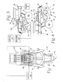
- FIG. 2 is a perspective view of a part of a potato seed planting apparatus, according to the present invention, including six laterally spaced row/planting units, each shown in schematic form;
- FIG. 3 is a partial cross-sectional, partial schematic, view of the potato seed planting apparatus in FIG. 2 and with a wheeled support incorporated;
- FIG. 4 is a bottom view of one of the row/planting units on the potato seed planting apparatus in FIGS. 2 and 3 ;
- FIG. 5 is an elevation view of the row/planting unit in FIG. 4 from one side thereof;
- FIG. 6 is a view as in FIG. 5 from the opposite side;
- FIG. 7 is a perspective view of a portion of the row/planting unit in FIGS. 4-6 ;
- FIG. 8 is a view as in FIG. 7 from a different perspective
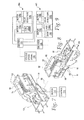
- FIG. 9 is a schematic representation of two representative row/planting units and a control for components thereof.
- FIG. 10 is a schematic representation of a towing vehicle and the control in FIG. 9 ;
- FIG. 11 is a schematic representation of the control in FIG. 9 and potential inputs thereto;
- FIG. 12 is a fragmentary, side elevation, view of a conventional row/planting unit into which the invention can be incorporated;
- FIG. 13 is a schematic representation of another conventional form of row/planting unit into which the invention can be incorporated.
- FIG. 14 is a flow diagram representation of a method of planting potato seed, according to the invention.
- the invention will be described initially as incorporated into one specific form of seed planting apparatus 10 , of the type shown schematically in FIG. 1 .
- the invention can be incorporated into virtually an unlimited number of different apparatus designs within the generic showing of FIG. 1 .
- Exemplary details of the apparatus 10 described below should not be viewed as limiting.
- the exemplary inventive seed planting apparatus 10 in FIGS. 2-11 , has a frame 12 on a support 14 .
- the support 14 has a plurality of wheels 36 that support the frame 12 on the subjacent field surface 38 between adjacent planting rows 39 .
- the frame 12 has a forwardly projecting bar 40 that is hitched to the towing vehicle 16 that is operated to advance the seed planting apparatus 10 in a forward travel path, as indicated by the arrow 42 .
- the frame 12 is configured to support six laterally spaced row/planting units 46 .
- the row/planting units 46 (hereinafter, “planting units”) are shown in schematic form in FIG. 2 and in detail in FIGS. 3-8 .
- a container 22 extends substantially the full width of the frame 12 and defines a receptacle 48 for a supply 20 of individual potato seeds 50 .
- the receptacle 48 converges downwardly so that the potato seeds 50 feed by gravitational force towards the planting units 46 .
- a series of laterally spaced dividers 52 cause a widthwise displacement of the potato seed 50 for even distribution to the planting units 46 .
- planting units 46 Before the details of the planting units 46 , and the remainder of the inventive seed planting apparatus 10 , are described, the basic structure and operation of the seed planting units 46 will be described. It should be understood that while the planting units 46 are shown to be the same, they might have different constructions on a single planting apparatus.
- Each planting unit 46 has a shoe 54 at a leading end.
- the shoe 54 is supported on a subframe 56 through a linkage at 58 and is biased, as through one or more springs 60 , downwardly relative to the subframe 56 against the field surface 38 .
- the subframe 56 is fixed to the remainder of the frame 12 through appropriate mounting structure at 62 . This biasing arrangement allows the shoe 54 to deflect upwardly relative to the frame 12 to avoid damage as upon impacting an obstruction in the field.
- a boot 64 moves as one piece with the shoe 54 in a following relationship. As the shoe 54 is advanced in the travel path, the shoe 54 creates a furrow 66 , with the boot 64 defining a funneling surface 68 to guide individual, downwardly traveling potato seeds 50 into the furrow 66 .
- a pair of spring-loaded, laterally spaced closing disks 70 follow the boot 64 and are angularly situated to accumulate soil at the sides of a furrow 66 so that the soil covers the potato seeds 50 deposited in the furrow 66 and forms a hill, generally peaked at the center of each row 39 .
- the shoe 54 , boot 64 , and closing disks 70 collectively make up the aforementioned soil handling assembly 24 ( FIG. 1 ).
- the individual potato seeds 50 are sized to approximately three ounces. Depending upon the size and type of potato, the individual potato seeds 50 might be uncut or cut to fall within the optimum size range for handling and growth.
- the seed feeding assembly at 28 is provided to intercept downwardly traveling potato seeds 50 at the bottom region of the container 22 .
- the feeding assembly 28 consists of an endless belt 76 that is trained around parallel rollers 78 a , 78 b , 78 c , 78 d , with the roller 78 d being rotated by a drive 80 around a laterally extending axis 81 .
- the drive 80 will typically be an hydraulic motor or an electric motor.
- the endless belt 76 is defined by a plurality of parallel rods 82 , with lengths extending laterally, joined to produce the endless shape, as through a connecting web 84 .
- the arrangement of the rods 82 causes potato seed 50 placed against the belt 76 to be gripped and advanced forwardly in the direction of the arrow 86 as the belt 76 is driven.
- the drive 80 shown schematically in FIG. 3 , is an hydraulic motor, or alternatively an electric motor, that turns a sprocket 88 that drives an endless chain 90 engaged with a sprocket 92 that turns with the roller 78 d.
- the seed discharge assembly at 26 that causes potato seed 50 advanced from the container 22 through the feeding assembly 28 to be discharged in controlled intervals into the furrows 66 .
- the discharge assembly 26 consists of a plurality of components 96 that are movable around a laterally extending axis 98 .
- Each of the components 96 projects generally radially from a hub 100 that turns around the axis 98 relative to the subframe 56 .
- Each of the components 96 is designed to pick up a single potato seed 50 and discharge the same into a furrow 66 for each rotation of the hub 100 .
- Each component 96 has a tube/conduit 102 with a generally “J” shape, terminating at a cup 104 .
- the cup 104 may have a flexible shape made from a material such as urethane, configured to allow nesting of an individual potato seed 50 .
- a valve structure 106 is integrated into the hub 100 and is operated through a drive/motor 108 . Operation of the motor 108 is coordinated by a central control system/control 110 (hereinafter “control 110 ”).
- the motor 108 may be an hydraulic motor or an electric motor.
- a collection location at 112 is provided to accept a discrete quantity of the potato seeds 50 delivered by the endless belt 76 .
- the component 96 identified at the location of the component 96 a in FIG. 3 is advanced through the accumulation of potato seed 50 at the collection location 112 .
- the control 110 causes the valve structure 106 to place the tube/conduit 102 on the component 96 a to be in communication with an evacuation source 114 , that creates a negative pressure/vacuum at the cup 104 .
- the J-shaped tube/conduit 102 on the component 96 a is configured so that it tends to scoop up a potato seed 50 in the accumulated potato seeds at the collection location 112 .
- the vacuum maintains the scooped potato seed 50 nested in the cup 104 .
- the vacuum is maintained as the hub 100 turns so that the component 96 with the held potato seed 50 reaches the location of the component identified at 96 b in FIG. 3 .
- the control 110 causes the valve structure 106 to place the tube/conduit 102 in communication with a pressurized fluid source 116 which generates a discharge force that assists gravitational forces, thereby causing the potato seed 50 held by the cup 104 to separate and drop/discharge into the furrow 66 .
- the components 96 function in the same manner and are spaced at regular intervals around the axis 98 . With the planting unit 18 advanced at a uniform travel speed and the hub 100 turning at a constant rotational speed, potato seed 50 is planted at regular time and distance intervals.
- the hub 100 is driven by the motor 108 or another drive/motor 118 with operation thereof coordinated through the control 110 .
- the motor 118 may be an hydraulic motor or an electric motor. The operation will be described below with the motor 118 driving the hub 100 .
- An encoder 120 ( FIG. 9 ) is provided to sense a rotational speed of a shaft 122 that rotates with the hub 100 and components 96 , together making up a seed wheel 124 that rotates as a unit.
- exemplary planter units 46 a , 46 b are independently operable in different manners through the control 110 .
- the motors 108 a , 118 a and 108 b , 118 b can all be independently operable through the control 110 .
- the motors 118 a , 118 b may be placed in a first state wherein they cause their respective seed wheels 124 and associated components 96 to turn at the same speed.
- This speed may be coordinated with the speed of the towing vehicle 16 , determined through a processed speed signal 126 to plant the potato seed 50 at a predetermined and constant time and distance interval for the two rows 39 in which the planting units 46 discharge potato seed 50 .
- the operation of the motors 108 a , 108 b is coordinated with operation of the motors 118 a , 118 b through the control 110 as appropriate.
- a second state can be selected wherein the seed wheels 124 on the planting units 46 a , 46 b are driven at different speeds by their respective motors 118 a , 118 b.
- neither of the seeds wheels 124 is driven as the towing vehicle 16 is advanced.
- the seed wheel 124 on one of the planting units 46 a , 46 b is driven, while the other seed wheel 124 is not.
- planting units 46 a , 46 b are described in FIG. 9 , any number of independently operable planting units 46 might be utilized.
- inputs to the control 110 may be made by an operator from the towing vehicle 16 , as with the user thereof in an operator seat 128 .
- One or more actuators 130 are accessible to the operator on/in the towing vehicle 16 .
- Various manual inputs might be made.
- programmed inputs 132 may be made to the control 110 .
- the inputs 132 may be predetermined based upon an earlier mapping of a particular field.
- the inputs 132 may be coordinated with GPS signals 134 to perform prescription planting. Information from yield maps, soil testing, and moisture evaluations can be used to individually control operation of the planting units 46 .
- the operator might plant using different seed spacing in different rows at one time.
- the operator may turn individual, or all, planting units 46 on and off strategically by stopping operation of the seed wheels 124 , as at the ends of fields and in other areas.
- the operator may vary the planting rate based upon particular field conditions.
- the discharge time intervals for the potato seeds can be changed.
- the actual discharge distance interval is a product of both the turning speed of the seed wheels 124 and the travel speed of their respective planting unit 46 .
- Component operation can be coordinated through the control 100 to produce the desired planting distance interval, regardless of the travel speed of the towing vehicle 16 .
- the control 110 may coordinate components so that the turning speed of the seed wheels 124 automatically changes as the rate of speed of the towing vehicle 16 in its travel path changes.
- a sensor 136 may be provided to identify a level of accumulated potato seed at the collection location 112 .
- the control 110 processes a signal from the sensor 136 to cause the drive 80 to cause turning of the roller 78 d at different speeds or stop, depending upon the detected level of potato seed 50 .
- the drives/motors 80 , 108 , 118 might be electrically and/or hydraulically operated. One or more of the drives/motors 80 , 108 , 118 may be driven by the power take-off 32 on the towing vehicle 16 .
- One skilled in the art could readily devise one or more electric/hydraulic circuits to facilitate coordinated operation, as described above, through the control(s) 110 .
- the planting units 46 are connected to the frame 12 through the aforementioned mounting structure at 62 that allows the planting units 46 to move independently in a vertically guided manner relative to the frame 12 .
- the movable components 96 do not have to have the construction as hereinabove described. Virtually an unlimited number of different movable components that operate in the same general manner are contemplated.
- an endless member 140 trained around spaced rollers 142 , 144 , may be utilized to convey the potato seed 50 from a corresponding collection location 112 ′ to a location at 146 whereat they are discharged to an underlying furrow 66 .
- a series of cup-shaped movable components 96 ′ are spaced at uniform intervals along the length of the member 140 . As the components 96 ′ move upwardly, they scoop and hold individual potato seeds 50 .
- the carried potato seeds 50 release and fall gravitationally to the immediately upstream component 96 ′.
- the seeds 50 separate.
- the movable components 96 ′′ may be in the form of picks projecting at regular intervals from a disk 150 that turns around an axis. For each rotation of the disk 150 , each pick 96 ′′ impales a seed 50 so that the seed follows the pick 96 ′′ until it falls under its own weight off of the pick 96 ′′ at a spaced location and discharges into a furrow.
- the same structure and operation, described above for planting potato seed, can be used to apply fertilizer/chemical at various stages during a planting/growing cycle.
- the frame 12 may have its own propulsion unit to advance the frame 12 in a travel path over a field.
- a method of planting potato seed can be carried out as shown in flow diagram form in FIG. 14 .
- a potato seed planting apparatus As shown at block 156 , a potato seed planting apparatus, as described above, is obtained.
- a supply of potato seed is placed in a container on the potato seed planting apparatus.
- the potato seed planting apparatus is advanced in a travel path.
- the planting units are operated to continuously plant the potato seed in a subjacent field.
Landscapes
- Life Sciences & Earth Sciences (AREA)
- Soil Sciences (AREA)
- Environmental Sciences (AREA)
- Sowing (AREA)
Abstract
A potato seed planting apparatus has: a frame configured to be advanced over a subjacent field into which potato seed is planted; at least one container on the frame for a supply of potato seed; and a plurality of laterally spaced planting units on the frame. Each of the planting units is configured to cause potato seed from the at least one container to be discharged to the subjacent field at controlled time intervals as the potato seed planting apparatus is advanced in a travel path. First and second of the planting units are configured so that the discharge time intervals for potato seeds from the first planting unit are different than the discharge time intervals for potato seeds from the second planting unit with the potato seed planting apparatus advanced at a first speed in the travel path.
Description
- This invention relates to potato seed planting apparatus and, more particularly, to an apparatus having multiple row/planting units that simultaneously create furrows in subjacent soil, discharge potato seed from a supply thereof at controlled time intervals into the furrows, and cover the discharged seed continuously as the apparatus is advanced in a travel path. The invention is also directed to a method of using the apparatus.
- A number of different row/planting unit designs currently exist for planting potato seed continuously as the row/planting units are advanced over a field. The overall construction and operation of potato seed planting apparatus incorporating these row/planting units are basically the same, as shown schematically in
FIG. 1 . - In
FIG. 1 , the potatoseed planting apparatus 10 consists of aframe 12 carried upon asupport 14, that typically has a wheeled construction. Theframe 12 is connected to atowing vehicle 16 that is operated to advance theapparatus 10 in a travel path. - The
apparatus 10 incorporates a plurality of row/planting units 18, of like construction, supported upon theframe 12 in laterally spaced relationship. Each row/planting unit 18 is designed to plant individual potato seeds, from asupply 20 thereof, into a single furrow/planting row. The seeds from thesupply 20 are accumulated in one ormore containers 22 from which the seeds are delivered to the row/planting units 18. - Each row/
planting unit 18 has asoil handling assembly 24 that creates a furrow for potato seed in the subjacent soil and redistributes the soil to cover the potato seed after it is discharged into the furrow. - A
discharge assembly 26 causes individual potato seeds to be serially discharged into the furrows as theapparatus 10 is advanced. Theseed discharge assembly 26 is continuously supplied through aseed feeding assembly 28 that controllably delivers potato seed from the container(s) 22 thereto. - The
seed discharge assembly 26 andseed feeding assembly 28 are operated by one ormore drives 30, operated as by a power take-off 32 on thetowing vehicle 16. - In the basic construction, one or
more sensors 34 identify the speed of thetowing vehicle 16 and generate a representative signal that controls operation of the drive(s) 30 so that the potato seed is discharged at controlled time intervals correlated to the speed of thetowing vehicle 16, thereby to cause the potato seed to be planted at regular predetermined distance intervals. - In this basic construction, the row/
planting units 18 are interconnected so that they function in the same manner with uniform time interval seed discharge to effect the same distance interval planting of potato seeds in as many rows as there are row/planting units 18 as the row/planting units 18 advance in straight paths. This basic construction has been used to date since it performs adequately in planting over the majority of an area of most field layouts. That is because the apparatus will perform most of the planting over extended straight travel paths such that no changing of the discharge time intervals from one row to the next is critical. - One drawback with uniform operation of row/planting units is that the distance interval between planted potato seeds from one row to the next varies undesirably as turns are navigated. As turning is carried out, the row/planting units move in arcs with different radii as a result of which the potato seeds discharging at constant time intervals are caused to be placed in furrows at different distance intervals.
- Another limitation that this conventional construction has is that it does not permit prescription planting based upon variations in potato seed placement, from one row to the next, as dictated by uneven yields determined from one or more prior planting seasons.
- The first problem is often dealt with by interrupting operation of the row/planting units when sharp turns or turn-arounds are performed. In certain field configurations, this could lead to a significant loss in yield. The alternative is to continue with the uneven planting which may, again depending upon the configuration of the field, lead to a significant waste of potato seed.
- In spite of the above-described problems that have existed for decades in the industry, those planting potato seeds have continued to use existing designs given the unavailability of alternative constructions.
- In one form, the invention is directed to a potato seed planting apparatus having: a frame configured to be advanced over a subjacent field to which potato seed is to be planted; at least one container on the frame for a supply of potato seed; and a plurality of laterally spaced planting units on the frame. Each of the planting units is configured to cause potato seed from the at least one container to be discharged to the subjacent field at controlled time intervals as the potato seed planting apparatus is advanced in a travel path. First and second of the planting units are configured so that the discharge time intervals for potato seeds from the first planting unit are different than the discharge time intervals for potato seeds from the second planting unit with the potato seed planting apparatus advanced at a first speed in the travel path.
- In one form, the first and second planting units each has at least one movable component that is configured to engage potato seeds and advance the engaged potato seeds in a predetermined path to cause individual engaged potato seeds to be picked up with the at least one movable component at a first path location and discharged to the subjacent field with the at least one movable component advanced in the predetermined path to a second path location.
- In one form, the first planting unit has a first drive for advancing the at least one movable component on the first planting unit. The second planting unit has a second drive for advancing the at least one movable component on the second planting unit. The potato seed planting apparatus further includes a control system that is configured to operate the drives to selectively advance the at least one movable component on the first and second planting units at different speeds.
- In one form, the first and second drives each is one of an electric and an hydraulic motor.
- In one form, the control system and first and second drives are configured so that through the control system the first and second drives can be selectively changed between: a) a first state wherein the at least one movable component on the first and second planting units are driven at the same speed; b) a second state wherein the at least one movable component on the first and second planting units are driven at different speeds; c) a third state wherein the at least one movable component on the first and second planting units are not driven; and d) a fourth state wherein the at least one movable component on only one of the first and second planting units is driven.
- In one form, the potato seed planting apparatus is provided in combination with a towing unit that is connected to the frame and operable to advance the frame over a subjacent field. The towing unit has an operator seat for a user of the potato seed planting apparatus. The control system has at least one actuator that is accessible to a user in the operator seat and operable to control operation of the first and second drives.
- In one form, the control unit is configured to receive a programmed input through which at least one of: a) the drive units are changed between different states in a manner customized to a particular planting field; and b) with the first and second drives in the second state a relative speed of the at least one movable component on the first and second planting units is changed in a manner customized to a particular planting field.
- In one form, each of the planting units is configured to discharge potato seeds to a single planting row.
- In one form, the potato seed planting apparatus is provided in combination with a supply of potato seeds in the container.
- In one form, each of the planting units is configured to create a continuous furrow for receiving potato seeds as the potato seed planting apparatus is advanced in the travel path.
- In one form, each of the planting units is configured to continuously close a furrow after potato seeds are received in the furrow as the potato seed planting apparatus is advanced in the travel path.
- In one form, the first and second planting units and frame are configured so that the first and second planting units are movable together vertically in a guided manner relative to the frame.
- In one form, the at least one movable component on at least one of the planting units is moved around an axis to advance potato seed in the predetermined path.
- In one form, the at least one movable component on at least one of the planting units is moved in an endless path to advance potato seed in the predetermined path.
- In one form, at least one of the planting units is configured to generate a negative pressure to hold the potato seed on its respective, advancing, at least one movable component.
- In one form, the control system is configured to automatically set an advancing speed of the at least one movable component on at least one of the planting units based upon a speed of the potato seed planting apparatus in the travel path.
- In one form, the potato seed planting apparatus further includes at least one feeding assembly configured to deliver potato seed from the at least one container to at least one location at which potato seed is picked up by the at least one movable component on the first and second planting units.
- In one form, the invention is directed to a method of planting potato seed. The method includes the steps of: obtaining the potato seed planting apparatus described above; placing a supply of potato seeds in the container; advancing the potato seed planting apparatus in the travel path; and with the potato seed planting apparatus advancing in the travel path, operating the planting units to continuously plant the potato seed in the subjacent field.
- In one form, the potato seed planting apparatus further includes a control system configured to control operation of the drives. The method of planting potato seeds further includes the step of manually operating the drives through the control unit.
- In one form, the potato seed planting apparatus further includes a control system configured to control operation of the drives. The method of planting potato seeds further includes the step of obtaining a programmed input to the control unit that automatically controls operation of the drives based upon predetermined conditions of a particular field.
-
FIG. 1 is a schematic representation of an exemplary prior art system into which the present invention can be incorporated; -
FIG. 2 is a perspective view of a part of a potato seed planting apparatus, according to the present invention, including six laterally spaced row/planting units, each shown in schematic form; -
FIG. 3 is a partial cross-sectional, partial schematic, view of the potato seed planting apparatus inFIG. 2 and with a wheeled support incorporated; -
FIG. 4 is a bottom view of one of the row/planting units on the potato seed planting apparatus inFIGS. 2 and 3 ; -
FIG. 5 is an elevation view of the row/planting unit inFIG. 4 from one side thereof; -
FIG. 6 is a view as inFIG. 5 from the opposite side; -
FIG. 7 is a perspective view of a portion of the row/planting unit inFIGS. 4-6 ; -
FIG. 8 is a view as inFIG. 7 from a different perspective; -
FIG. 9 is a schematic representation of two representative row/planting units and a control for components thereof; -
FIG. 10 is a schematic representation of a towing vehicle and the control inFIG. 9 ; -
FIG. 11 is a schematic representation of the control inFIG. 9 and potential inputs thereto; -
FIG. 12 is a fragmentary, side elevation, view of a conventional row/planting unit into which the invention can be incorporated; -
FIG. 13 is a schematic representation of another conventional form of row/planting unit into which the invention can be incorporated; and -
FIG. 14 is a flow diagram representation of a method of planting potato seed, according to the invention. - The invention will be described initially as incorporated into one specific form of
seed planting apparatus 10, of the type shown schematically inFIG. 1 . The invention can be incorporated into virtually an unlimited number of different apparatus designs within the generic showing ofFIG. 1 . Exemplary details of theapparatus 10 described below should not be viewed as limiting. - The exemplary inventive
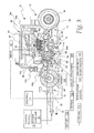
seed planting apparatus 10, inFIGS. 2-11 , has aframe 12 on asupport 14. Thesupport 14 has a plurality ofwheels 36 that support theframe 12 on thesubjacent field surface 38 betweenadjacent planting rows 39. - The
frame 12 has a forwardly projectingbar 40 that is hitched to the towingvehicle 16 that is operated to advance theseed planting apparatus 10 in a forward travel path, as indicated by thearrow 42. - As seen in
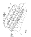
FIG. 2 , wherein part of theframe 12 is shown independently of thesupport 14 and staged on supportingfeet 44, theframe 12 is configured to support six laterally spaced row/planting units 46. The row/planting units 46 (hereinafter, “planting units”) are shown in schematic form inFIG. 2 and in detail inFIGS. 3-8 . - A
container 22 extends substantially the full width of theframe 12 and defines areceptacle 48 for asupply 20 ofindividual potato seeds 50. Thereceptacle 48 converges downwardly so that thepotato seeds 50 feed by gravitational force towards theplanting units 46. A series of laterally spaceddividers 52 cause a widthwise displacement of thepotato seed 50 for even distribution to theplanting units 46. - Before the details of the
planting units 46, and the remainder of the inventiveseed planting apparatus 10, are described, the basic structure and operation of theseed planting units 46 will be described. It should be understood that while theplanting units 46 are shown to be the same, they might have different constructions on a single planting apparatus. - Each
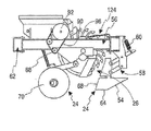
planting unit 46 has ashoe 54 at a leading end. Theshoe 54 is supported on asubframe 56 through a linkage at 58 and is biased, as through one ormore springs 60, downwardly relative to thesubframe 56 against thefield surface 38. Thesubframe 56 is fixed to the remainder of theframe 12 through appropriate mounting structure at 62. This biasing arrangement allows theshoe 54 to deflect upwardly relative to theframe 12 to avoid damage as upon impacting an obstruction in the field. - A
boot 64 moves as one piece with theshoe 54 in a following relationship. As theshoe 54 is advanced in the travel path, theshoe 54 creates afurrow 66, with theboot 64 defining a funnelingsurface 68 to guide individual, downwardly travelingpotato seeds 50 into thefurrow 66. - A pair of spring-loaded, laterally spaced
closing disks 70 follow theboot 64 and are angularly situated to accumulate soil at the sides of afurrow 66 so that the soil covers thepotato seeds 50 deposited in thefurrow 66 and forms a hill, generally peaked at the center of eachrow 39. - The
shoe 54,boot 64, andclosing disks 70 collectively make up the aforementioned soil handling assembly 24 (FIG. 1 ). - Typically, the
individual potato seeds 50 are sized to approximately three ounces. Depending upon the size and type of potato, theindividual potato seeds 50 might be uncut or cut to fall within the optimum size range for handling and growth. - The seed feeding assembly at 28 is provided to intercept downwardly traveling
potato seeds 50 at the bottom region of thecontainer 22. The feedingassembly 28 consists of anendless belt 76 that is trained aroundparallel rollers roller 78 d being rotated by adrive 80 around a laterally extendingaxis 81. Thedrive 80 will typically be an hydraulic motor or an electric motor. In this embodiment, theendless belt 76 is defined by a plurality ofparallel rods 82, with lengths extending laterally, joined to produce the endless shape, as through a connectingweb 84. The arrangement of therods 82 causespotato seed 50 placed against thebelt 76 to be gripped and advanced forwardly in the direction of the arrow 86 as thebelt 76 is driven. - In the form depicted, the
drive 80, shown schematically inFIG. 3 , is an hydraulic motor, or alternatively an electric motor, that turns asprocket 88 that drives anendless chain 90 engaged with asprocket 92 that turns with theroller 78 d. - The seed discharge assembly at 26 that causes
potato seed 50 advanced from thecontainer 22 through the feedingassembly 28 to be discharged in controlled intervals into thefurrows 66. Thedischarge assembly 26 consists of a plurality ofcomponents 96 that are movable around a laterally extendingaxis 98. Each of thecomponents 96 projects generally radially from ahub 100 that turns around theaxis 98 relative to thesubframe 56. Each of thecomponents 96 is designed to pick up asingle potato seed 50 and discharge the same into afurrow 66 for each rotation of thehub 100. - Each
component 96 has a tube/conduit 102 with a generally “J” shape, terminating at acup 104. Thecup 104 may have a flexible shape made from a material such as urethane, configured to allow nesting of anindividual potato seed 50. - A
valve structure 106 is integrated into thehub 100 and is operated through a drive/motor 108. Operation of themotor 108 is coordinated by a central control system/control 110 (hereinafter “control 110”). Themotor 108 may be an hydraulic motor or an electric motor. - To facilitate operation of the
discharge assembly 26, a collection location at 112 is provided to accept a discrete quantity of thepotato seeds 50 delivered by theendless belt 76. - At the initiation of a single turn of the
hub 100, thecomponent 96 identified at the location of thecomponent 96 a inFIG. 3 is advanced through the accumulation ofpotato seed 50 at thecollection location 112. Thecontrol 110 causes thevalve structure 106 to place the tube/conduit 102 on thecomponent 96 a to be in communication with anevacuation source 114, that creates a negative pressure/vacuum at thecup 104. The J-shaped tube/conduit 102 on thecomponent 96 a is configured so that it tends to scoop up apotato seed 50 in the accumulated potato seeds at thecollection location 112. The vacuum maintains the scoopedpotato seed 50 nested in thecup 104. - The vacuum is maintained as the
hub 100 turns so that thecomponent 96 with the heldpotato seed 50 reaches the location of the component identified at 96 b inFIG. 3 . At this point, thecontrol 110 causes thevalve structure 106 to place the tube/conduit 102 in communication with a pressurizedfluid source 116 which generates a discharge force that assists gravitational forces, thereby causing thepotato seed 50 held by thecup 104 to separate and drop/discharge into thefurrow 66. Thecomponents 96 function in the same manner and are spaced at regular intervals around theaxis 98. With theplanting unit 18 advanced at a uniform travel speed and thehub 100 turning at a constant rotational speed,potato seed 50 is planted at regular time and distance intervals. - The
hub 100 is driven by themotor 108 or another drive/motor 118 with operation thereof coordinated through thecontrol 110. Themotor 118 may be an hydraulic motor or an electric motor. The operation will be described below with themotor 118 driving thehub 100. - An encoder 120 (
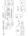
FIG. 9 ) is provided to sense a rotational speed of ashaft 122 that rotates with thehub 100 andcomponents 96, together making up aseed wheel 124 that rotates as a unit. - As shown in
FIG. 9 ,exemplary planter units control 110. For example, in eachplanting unit motors control 110. Through thecontrol 110, themotors respective seed wheels 124 and associatedcomponents 96 to turn at the same speed. This speed may be coordinated with the speed of the towingvehicle 16, determined through a processedspeed signal 126 to plant thepotato seed 50 at a predetermined and constant time and distance interval for the tworows 39 in which theplanting units 46discharge potato seed 50. The operation of themotors motors control 110 as appropriate. - A second state can be selected wherein the
seed wheels 124 on theplanting units respective motors - In a potential third state selectable through the
control 110, neither of theseeds wheels 124 is driven as the towingvehicle 16 is advanced. - In a potential fourth state, the
seed wheel 124 on one of theplanting units other seed wheel 124 is not. - While two
exemplary planting units FIG. 9 , any number of independentlyoperable planting units 46 might be utilized. - As shown in
FIG. 10 , inputs to thecontrol 110 may be made by an operator from the towingvehicle 16, as with the user thereof in anoperator seat 128. One ormore actuators 130 are accessible to the operator on/in the towingvehicle 16. Various manual inputs might be made. - As shown in
FIG. 11 , programmedinputs 132 may be made to thecontrol 110. Theinputs 132 may be predetermined based upon an earlier mapping of a particular field. Theinputs 132 may be coordinated withGPS signals 134 to perform prescription planting. Information from yield maps, soil testing, and moisture evaluations can be used to individually control operation of theplanting units 46. - Combinations of manual and pre-programmed inputs are also contemplated.
- As an example of how the operator might use the inventive system, the operator might plant using different seed spacing in different rows at one time. Alternatively, the operator may turn individual, or all,
planting units 46 on and off strategically by stopping operation of theseed wheels 124, as at the ends of fields and in other areas. As a further alternative, the operator may vary the planting rate based upon particular field conditions. - By controlling the turning speed of the
speed wheels 124, the discharge time intervals for the potato seeds can be changed. The actual discharge distance interval is a product of both the turning speed of theseed wheels 124 and the travel speed of theirrespective planting unit 46. Component operation can be coordinated through thecontrol 100 to produce the desired planting distance interval, regardless of the travel speed of the towingvehicle 16. - The
control 110 may coordinate components so that the turning speed of theseed wheels 124 automatically changes as the rate of speed of the towingvehicle 16 in its travel path changes. - Some additional details of the overall system will now be described.
- As shown in
FIG. 3 , asensor 136 may be provided to identify a level of accumulated potato seed at thecollection location 112. Thecontrol 110 processes a signal from thesensor 136 to cause thedrive 80 to cause turning of theroller 78 d at different speeds or stop, depending upon the detected level ofpotato seed 50. - As noted above, the system described is exemplary in nature only. The drives/
motors motors off 32 on the towingvehicle 16. One skilled in the art could readily devise one or more electric/hydraulic circuits to facilitate coordinated operation, as described above, through the control(s) 110. - The
planting units 46 are connected to theframe 12 through the aforementioned mounting structure at 62 that allows theplanting units 46 to move independently in a vertically guided manner relative to theframe 12. - The
movable components 96 do not have to have the construction as hereinabove described. Virtually an unlimited number of different movable components that operate in the same general manner are contemplated. As one example, as shown inFIG. 12 , as an alternative to theseed wheels 124, anendless member 140, trained around spacedrollers potato seed 50 from acorresponding collection location 112′ to a location at 146 whereat they are discharged to anunderlying furrow 66. A series of cup-shapedmovable components 96′ are spaced at uniform intervals along the length of themember 140. As thecomponents 96′ move upwardly, they scoop and holdindividual potato seeds 50. As the vertically advancingcomponents 96′ change direction to downwardly at thelocation 148, the carriedpotato seeds 50 release and fall gravitationally to the immediatelyupstream component 96′. As thecomponents 96′ change direction at thelocation 146, theseeds 50 separate. - In an alternative form as shown in
FIG. 13 , themovable components 96″ may be in the form of picks projecting at regular intervals from adisk 150 that turns around an axis. For each rotation of thedisk 150, each pick 96″ impales aseed 50 so that the seed follows thepick 96″ until it falls under its own weight off of thepick 96″ at a spaced location and discharges into a furrow. - The same structure and operation, described above for planting potato seed, can be used to apply fertilizer/chemical at various stages during a planting/growing cycle.
- While the invention has been described using a
separate towing vehicle 16, theframe 12 may have its own propulsion unit to advance theframe 12 in a travel path over a field. - With the inventive structure, a method of planting potato seed can be carried out as shown in flow diagram form in
FIG. 14 . - As shown at
block 156, a potato seed planting apparatus, as described above, is obtained. - As shown at
block 158, a supply of potato seed is placed in a container on the potato seed planting apparatus. - As shown at
block 160, the potato seed planting apparatus is advanced in a travel path. - As shown at
block 162, with the potato seed planting apparatus advancing in its travel path, the planting units are operated to continuously plant the potato seed in a subjacent field. - The foregoing disclosure of specific embodiments is intended to be illustrative of the broad concepts comprehended by the invention.
Claims (20)
1. A potato seed planting apparatus comprising:
a frame configured to be advanced over a subjacent field to which potato seed is to be planted;
at least one container on the frame for a supply of potato seed; and
a plurality of laterally spaced planting units on the frame,
each of the planting units configured to cause potato seed from the at least one container to be discharged to the subjacent field at controlled time intervals as the potato seed planting apparatus is advanced in a travel path,
first and second of the planting units configured so that the discharge time intervals for potato seeds from the first planting unit are different than the discharge time intervals for potato seeds from the second planting unit with the potato seed planting apparatus advanced at a first speed in the travel path.
2. The potato seed planting apparatus according to claim 1 wherein the first and second planting units each has at least one movable component that is configured to engage potato seeds and advance the engaged potato seeds in a predetermined path to cause individual engaged potato seeds to be picked up with the at least one movable component at a first path location and discharged to the subjacent field with the at least one movable component advanced in the predetermined path to a second path location.
3. The potato seed planting apparatus according to claim 2 wherein the first planting unit has a first drive for advancing the at least one movable component on the first planting unit and the second planting unit has a second drive for advancing the at least one movable component on the second planting unit and the potato seed planting apparatus further comprises a control system that is configured to operate the drives to selectively advance the at least one movable component on the first and second planting units at different speeds.
4. The potato seed planting apparatus according to claim 3 wherein the first and second drives each comprises one of an electric and hydraulic motor.
5. The potato seed planting apparatus according to claim 3 wherein the control system and first and second drives are configured so that through the control system the first and second drives can be selectively changed between: a) a first state wherein the at least one movable component on the first and second planting units are driven at the same speed; b) a second state wherein the at least one movable component on the first and second planting units are driven at different speeds; c) a third state wherein the at least one movable component on the first and second planting units are not driven; and d) a fourth state wherein the at least one movable component on only one of the first and second planting units is driven.
6. The potato seed planting apparatus according to claim 5 in combination with a towing unit that is connected to the frame and operable to advance the frame over a subjacent field, the towing unit comprising an operator seat for a user of the potato seed planting apparatus, and the control system comprises at least one actuator that is accessible to a user in the operator seat and operable to control operation of the first and second drives.
7. The potato seed planting apparatus according to claim 5 wherein the control unit is configured to receive a programmed input through which at least one of: a) the drive units are changed between different states in a manner customized to a particular planting field; and b) with the first and second drives in the second state a relative speed of the at least one movable component on the first and second planting units is changed in a manner customized to a particular planting field.
8. The potato seed planting apparatus according to claim 1 wherein each of the planting units is configured to discharge potato seeds to a single planting row.
9. The potato seed planting apparatus according to claim 1 in combination with a supply of potato seeds in the container.
10. The potato seed planting apparatus according to claim 1 wherein each of the planting units is configured to create a continuous furrow for receiving potato seeds as the potato seed planting apparatus is advanced in the travel path.
11. The potato seed planting apparatus according to claim 10 wherein each of the planting units is configured to continuously close the furrow after potato seeds are received in the furrow as the potato seed planting apparatus is advanced in the travel path.
12. The potato seed planting apparatus according to claim 1 wherein the first and second planting units and frame are configured so that the first and second planting units are movable together vertically in a guided manner relative to the frame.
13. The potato seed planting apparatus according to claim 2 wherein the at least one movable component on at least one of the planting units is moved around an axis to advance potato seed in the predetermined path.
14. The potato seed planting apparatus according to claim 2 wherein the at least one movable component on at least one of the planting units is moved in an endless path to advance potato seed in the predetermined path.
15. The potato seed planting apparatus according to claim 2 wherein at least one of the planting units is configured to generate a negative pressure to hold the potato seed on its respective advancing at least one movable component.
16. The potato seed planting apparatus according to claim 3 wherein the control system is configured to automatically set an advancing speed of the at least one movable component on at least one of the planting units based upon a speed of the potato seed planting apparatus in the travel path.
17. The potato seed planting apparatus according to claim 2 wherein the potato seed planting apparatus further comprises at least one feeding assembly configured to deliver potato seed from the at least one container to at least one location at which potato seed is picked up by the at least one movable component on the first and second planting units.
18. A method of planting potato seed, the method comprising the steps of:
obtaining the potato seed planting apparatus of claim 1 ;
placing a supply of potato seeds in the container;
advancing the potato seed planting apparatus in the travel path; and
with the potato seed planting apparatus advancing in the travel path, operating the planting units to continuously plant the potato seed in the subjacent field.
19. The method of planting potato seed according to claim 18 wherein the first and second planting units each has at least one movable component that is configured to engage potato seeds and advance the engaged potato seeds in a predetermined path to cause individual engaged potato seeds to be picked up with the at least one movable component at a first path location and discharged to the subjacent field with the at least one movable component advanced in the predetermined path to a second path location, wherein the first planting unit has a first drive for advancing the at least one movable component on the first planting unit and the second planting unit has a second drive for advancing the at least one movable component on the second planting unit and the potato seed planting apparatus further comprises a control system that is configured to operate the drives to selectively advance the at least one movable component on the first and second planting units at different speeds, wherein the potato seed planting apparatus further comprises a control system configured to control operation of the drives and further comprising the step of manually operating the drives through the control unit.
20. The method of planting potato seed according to claim 18 wherein the first and second planting units each has at least one movable component that is configured to engage potato seeds and advance the engaged potato seeds in a predetermined path to cause individual engaged potato seeds to be picked up with the at least one movable component at a first path location and discharged to the subjacent field with the at least one movable component advanced in the predetermined path to a second path location, wherein the first planting unit has a first drive for advancing the at least one movable component on the first planting unit and the second planting unit has a second drive for advancing the at least one movable component on the second planting unit and the potato seed planting apparatus further comprises a control system that is configured to operate the drives to selectively advance the at least one movable component on the first and second planting units at different seeds, wherein the potato seed planting apparatus further comprises a control system configured to control operation of the drives and further comprising the step of obtaining a programmed input to the control unit that automatically controls operation of the drives based upon predetermined conditions of a particular field.
Priority Applications (2)
| Application Number | Priority Date | Filing Date | Title |
|---|---|---|---|
| US15/360,099 US10165724B2 (en) | 2016-10-07 | 2016-11-23 | Potato seed planting apparatus and method of planting potato seed using the apparatus |
| CA2981776A CA2981776C (en) | 2016-10-07 | 2017-10-06 | Potato seed planting apparatus and method of planting potato seed using the apparatus |
Applications Claiming Priority (2)
| Application Number | Priority Date | Filing Date | Title |
|---|---|---|---|
| US201662405568P | 2016-10-07 | 2016-10-07 | |
| US15/360,099 US10165724B2 (en) | 2016-10-07 | 2016-11-23 | Potato seed planting apparatus and method of planting potato seed using the apparatus |
Publications (2)
| Publication Number | Publication Date |
|---|---|
| US20180098488A1 true US20180098488A1 (en) | 2018-04-12 |
| US10165724B2 US10165724B2 (en) | 2019-01-01 |
Family
ID=61829448
Family Applications (1)
| Application Number | Title | Priority Date | Filing Date |
|---|---|---|---|
| US15/360,099 Active US10165724B2 (en) | 2016-10-07 | 2016-11-23 | Potato seed planting apparatus and method of planting potato seed using the apparatus |
Country Status (2)
| Country | Link |
|---|---|
| US (1) | US10165724B2 (en) |
| CA (1) | CA2981776C (en) |
Cited By (7)
| Publication number | Priority date | Publication date | Assignee | Title |
|---|---|---|---|---|
| CN111010929A (en) * | 2019-12-18 | 2020-04-17 | 刘明 | An agricultural planting and cultivation device |
| CN111492764A (en) * | 2020-06-15 | 2020-08-07 | 江苏海洋大学 | Planting device for corm flower horticultural crops |
| CN111972093A (en) * | 2020-09-15 | 2020-11-24 | 黑龙江省农业科学院马铃薯研究所 | Sowing mechanism based on potato cultivation |
| EP4298882A1 (en) * | 2022-06-27 | 2024-01-03 | Dewulf B.V. | Planter for planting seedlings and method for controlling the operation of such a planter |
| CN118120411A (en) * | 2024-04-18 | 2024-06-04 | 创璟农业装备集团有限公司 | Potato seeding equipment |
| US20240268256A1 (en) * | 2021-07-20 | 2024-08-15 | Allan Equipment Manufacturing Ltd. | Potato Planter |
| WO2025135419A1 (en) * | 2023-12-21 | 2025-06-26 | 주식회사 세안코리아 | Seeder control system and operating method thereof |
Families Citing this family (21)
| Publication number | Priority date | Publication date | Assignee | Title |
|---|---|---|---|---|
| US8850995B2 (en) | 2009-02-02 | 2014-10-07 | Deere & Company | Seeding machine with seed delivery system |
| US8671856B2 (en) | 2009-02-02 | 2014-03-18 | Deere & Company | Planting unit for a seeding machine having blocking member to control hand-off of seed from a seed meter to a seed delivery system |
| US8850998B2 (en) | 2011-03-25 | 2014-10-07 | Deere & Company | Planting unit for a seeding machine having a seed meter and seed delivery system |
| US11058047B2 (en) | 2018-06-27 | 2021-07-13 | Deere & Company | Seeding system |
| US11051445B2 (en) | 2018-06-27 | 2021-07-06 | Deere & Company | Seeding system |
| US11064649B2 (en) | 2018-06-27 | 2021-07-20 | Deere & Company | Seeding system |
| US11516958B2 (en) | 2019-12-24 | 2022-12-06 | Cnh Industrial America Llc | Particle delivery system of an agricultural row unit |
| US11582899B2 (en) | 2019-12-24 | 2023-02-21 | Cnh Industrial America Llc | Particle delivery system of an agricultural row unit |
| US11490558B2 (en) | 2019-12-24 | 2022-11-08 | Cnh Industrial America Llc | Particle delivery system of an agricultural row unit |
| US11523556B2 (en) | 2019-12-24 | 2022-12-13 | Cnh Industrial America Llc | Particle delivery system of an agricultural row unit |
| US11553639B2 (en) | 2019-12-24 | 2023-01-17 | Cnh Industrial America Llc | Particle delivery system of an agricultural row unit |
| US11523555B2 (en) | 2019-12-24 | 2022-12-13 | Cnh Industrial America Llc | Particle delivery system of an agricultural row unit |
| US11553638B2 (en) | 2019-12-24 | 2023-01-17 | Cnh Industrial America Llc | Particle delivery system of an agricultural row unit |
| US11483963B2 (en) | 2019-12-24 | 2022-11-01 | Cnh Industrial America Llc | Particle delivery system of an agricultural row unit |
| US11589500B2 (en) | 2019-12-24 | 2023-02-28 | Cnh Industrial America Llc | Particle delivery system of an agricultural row unit |
| US11564344B2 (en) | 2019-12-24 | 2023-01-31 | Cnh Industrial America Llc | Particle delivery system of an agricultural row unit |
| US11596095B2 (en) | 2019-12-24 | 2023-03-07 | Cnh Industrial America Llc | Particle delivery system of an agricultural row unit |
| US11564346B2 (en) | 2019-12-24 | 2023-01-31 | Cnh Industrial America Llc | Particle delivery system of an agricultural row unit |
| US12532799B2 (en) | 2022-02-08 | 2026-01-27 | Kinze Manufacturing, Inc. | Singulator insert for 3D singulation and seed orientation |
| CN115226579B (en) * | 2022-05-27 | 2023-12-15 | 江苏大学 | Precision planting method, system and device for oil wheat field painting machinery |
| CN116171691A (en) * | 2022-12-07 | 2023-05-30 | 西华大学 | A planter suitable for lumpy seeds |
Family Cites Families (10)
| Publication number | Priority date | Publication date | Assignee | Title |
|---|---|---|---|---|
| AU1497788A (en) | 1987-03-17 | 1988-10-10 | Chetjack Limited | A method of validating data entered on a ticket and the like |
| US6520100B1 (en) | 1998-09-24 | 2003-02-18 | Ati | Twin row planter |
| US6244201B1 (en) * | 2000-06-19 | 2001-06-12 | Spudnik Equipment Company | Potato planter |
| US7395769B2 (en) | 2004-10-21 | 2008-07-08 | Jensen Layton W | Individual row rate control of farm implements to adjust the volume of crop inputs across wide implements in irregularly shaped or contour areas of chemical application, planting or seeding |
| US8868300B2 (en) | 2009-08-28 | 2014-10-21 | Raven Industries, Inc. | Multi-variable rate agricultural product application system, device and method |
| US8281725B2 (en) | 2009-11-24 | 2012-10-09 | Cnh America Llc | Directly driven seed meter hub drive |
| US8850997B2 (en) | 2011-04-25 | 2014-10-07 | Deere & Company | Planter and method of operating a planter with individual meter control |
| CA2879731C (en) | 2012-07-25 | 2021-04-20 | Precision Planting Llc | Systems, methods and apparatus for multi-row agricultural implement control and monitoring |
| US9313942B2 (en) * | 2012-10-23 | 2016-04-19 | Kinze Manufacturing, Inc. | Air seed meter housing with seed path relief |
| EP3041340A1 (en) | 2013-09-05 | 2016-07-13 | Kinze Manufacturing, Inc. | Multiple agricultural product application method and systems |
-
2016
- 2016-11-23 US US15/360,099 patent/US10165724B2/en active Active
-
2017
- 2017-10-06 CA CA2981776A patent/CA2981776C/en active Active
Cited By (8)
| Publication number | Priority date | Publication date | Assignee | Title |
|---|---|---|---|---|
| CN111010929A (en) * | 2019-12-18 | 2020-04-17 | 刘明 | An agricultural planting and cultivation device |
| CN111492764A (en) * | 2020-06-15 | 2020-08-07 | 江苏海洋大学 | Planting device for corm flower horticultural crops |
| CN111972093A (en) * | 2020-09-15 | 2020-11-24 | 黑龙江省农业科学院马铃薯研究所 | Sowing mechanism based on potato cultivation |
| US20240268256A1 (en) * | 2021-07-20 | 2024-08-15 | Allan Equipment Manufacturing Ltd. | Potato Planter |
| EP4298882A1 (en) * | 2022-06-27 | 2024-01-03 | Dewulf B.V. | Planter for planting seedlings and method for controlling the operation of such a planter |
| WO2025135419A1 (en) * | 2023-12-21 | 2025-06-26 | 주식회사 세안코리아 | Seeder control system and operating method thereof |
| KR102949000B1 (en) | 2023-12-21 | 2026-04-06 | 주식회사 세안코리아 | System for contorlling a seeding machine and operating method thereof |
| CN118120411A (en) * | 2024-04-18 | 2024-06-04 | 创璟农业装备集团有限公司 | Potato seeding equipment |
Also Published As
| Publication number | Publication date |
|---|---|
| CA2981776C (en) | 2021-05-25 |
| CA2981776A1 (en) | 2018-04-07 |
| US10165724B2 (en) | 2019-01-01 |
Similar Documents
| Publication | Publication Date | Title |
|---|---|---|
| US10165724B2 (en) | Potato seed planting apparatus and method of planting potato seed using the apparatus | |
| US10327378B2 (en) | Agricultural product delivery system | |
| US10667462B2 (en) | Multiple agricultural product application method and systems | |
| EP2517545B1 (en) | Seeding machine | |
| US20180020608A1 (en) | Metering system for an agricultural system | |
| US20180020610A1 (en) | Metering system for an agricultural system | |
| US11612100B2 (en) | Converging row unit for potato planter | |
| SE534736C2 (en) | Seeding procedure and apparatus at an agricultural machine | |
| US7174839B2 (en) | Seed planting system for multiple types of crops | |
| JP4600213B2 (en) | Seedling transplanter | |
| JP2003009613A (en) | Seeding machine |
Legal Events
| Date | Code | Title | Description |
|---|---|---|---|
| AS | Assignment |
Owner name: CRARY INDUSTRIES, INC., NORTH DAKOTA Free format text: ASSIGNMENT OF ASSIGNORS INTEREST;ASSIGNORS:NILSON, MICHAEL A.;ABRAHAMSON, KARL;REEL/FRAME:040811/0898 Effective date: 20161220 |
|
| STCF | Information on status: patent grant |
Free format text: PATENTED CASE |
|
| MAFP | Maintenance fee payment |
Free format text: PAYMENT OF MAINTENANCE FEE, 4TH YEAR, LARGE ENTITY (ORIGINAL EVENT CODE: M1551); ENTITY STATUS OF PATENT OWNER: LARGE ENTITY Year of fee payment: 4 |