US20180098465A1 - Electronic headset venting systems and methods - Google Patents
Electronic headset venting systems and methods Download PDFInfo
- Publication number
- US20180098465A1 US20180098465A1 US15/284,362 US201615284362A US2018098465A1 US 20180098465 A1 US20180098465 A1 US 20180098465A1 US 201615284362 A US201615284362 A US 201615284362A US 2018098465 A1 US2018098465 A1 US 2018098465A1
- Authority
- US
- United States
- Prior art keywords
- fan
- air
- electronic headset
- headset
- electronic
- Prior art date
- Legal status (The legal status is an assumption and is not a legal conclusion. Google has not performed a legal analysis and makes no representation as to the accuracy of the status listed.)
- Granted
Links
- 238000013022 venting Methods 0.000 title claims abstract description 33
- 238000000034 method Methods 0.000 title claims description 15
- 239000012530 fluid Substances 0.000 claims description 9
- 238000004891 communication Methods 0.000 claims description 7
- 239000000853 adhesive Substances 0.000 claims description 4
- 230000001070 adhesive effect Effects 0.000 claims description 4
- 239000006260 foam Substances 0.000 claims description 4
- 230000003190 augmentative effect Effects 0.000 description 3
- 210000003128 head Anatomy 0.000 description 3
- 230000008901 benefit Effects 0.000 description 2
- 210000001061 forehead Anatomy 0.000 description 2
- 230000003993 interaction Effects 0.000 description 2
- 230000008878 coupling Effects 0.000 description 1
- 238000010168 coupling process Methods 0.000 description 1
- 238000005859 coupling reaction Methods 0.000 description 1
- 230000001419 dependent effect Effects 0.000 description 1
- 239000013536 elastomeric material Substances 0.000 description 1
- 238000005516 engineering process Methods 0.000 description 1
- 238000001746 injection moulding Methods 0.000 description 1
- 239000007788 liquid Substances 0.000 description 1
- 239000007787 solid Substances 0.000 description 1
Images
Classifications
-
- G—PHYSICS
- G02—OPTICS
- G02B—OPTICAL ELEMENTS, SYSTEMS OR APPARATUS
- G02B27/00—Optical systems or apparatus not provided for by any of the groups G02B1/00 - G02B26/00, G02B30/00
- G02B27/01—Head-up displays
- G02B27/017—Head mounted
- G02B27/0176—Head mounted characterised by mechanical features
-
- H—ELECTRICITY
- H05—ELECTRIC TECHNIQUES NOT OTHERWISE PROVIDED FOR
- H05K—PRINTED CIRCUITS; CASINGS OR CONSTRUCTIONAL DETAILS OF ELECTRIC APPARATUS; MANUFACTURE OF ASSEMBLAGES OF ELECTRICAL COMPONENTS
- H05K7/00—Constructional details common to different types of electric apparatus
- H05K7/20—Modifications to facilitate cooling, ventilating, or heating
- H05K7/20954—Modifications to facilitate cooling, ventilating, or heating for display panels
- H05K7/20972—Forced ventilation, e.g. on heat dissipaters coupled to components
-
- G—PHYSICS
- G02—OPTICS
- G02B—OPTICAL ELEMENTS, SYSTEMS OR APPARATUS
- G02B27/00—Optical systems or apparatus not provided for by any of the groups G02B1/00 - G02B26/00, G02B30/00
- G02B27/02—Viewing or reading apparatus
- G02B27/028—Viewing or reading apparatus characterised by the supporting structure
-
- H—ELECTRICITY
- H05—ELECTRIC TECHNIQUES NOT OTHERWISE PROVIDED FOR
- H05K—PRINTED CIRCUITS; CASINGS OR CONSTRUCTIONAL DETAILS OF ELECTRIC APPARATUS; MANUFACTURE OF ASSEMBLAGES OF ELECTRICAL COMPONENTS
- H05K5/00—Casings, cabinets or drawers for electric apparatus
- H05K5/0017—Casings, cabinets or drawers for electric apparatus with operator interface units
-
- H—ELECTRICITY
- H05—ELECTRIC TECHNIQUES NOT OTHERWISE PROVIDED FOR
- H05K—PRINTED CIRCUITS; CASINGS OR CONSTRUCTIONAL DETAILS OF ELECTRIC APPARATUS; MANUFACTURE OF ASSEMBLAGES OF ELECTRICAL COMPONENTS
- H05K5/00—Casings, cabinets or drawers for electric apparatus
- H05K5/02—Details
- H05K5/0213—Venting apertures; Constructional details thereof
Definitions
- This application relates to electronic headsets and more particularly to virtual reality headsets, augmented reality headsets, and the like.
- Electronic headsets such as virtual reality headsets or augmented reality headsets, attach to a user's head and may be worn for extended periods of time without being removed.
- the electronic headsets are designed so that light does not enter an interior portion of the electronic headset and a user is able to see a display.
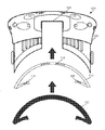
- FIG. 1 illustrates a top view of an electronic headset including a venting system, according to one embodiment of the present disclosure.
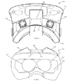
- FIG. 2 illustrates a front view of the electronic headset of FIG. 1 .
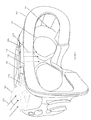
- FIG. 3 illustrates an isometric view of the electronic headset of FIG. 1 .
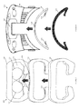
- FIG. 4 illustrates an exploded top view of the electronic headset and an air channel ring of the venting system.
- FIG. 5 illustrates an exploded front view similar to FIG. 4 .
- Electronic headsets such as virtual reality headsets or augmented reality headsets, may be worn on user's head for extended periods of time without being removed.
- the electronic headsets such as virtual reality headsets, may be designed so that light does not enter an interior area of a housing of the electronic headset and thereby allow a user to better view a lit display within the housing.
- a design of an electronic headset that does not allow light to enter may also suffer from a drawback that air is often unable to flow within the interior of the electronic headset when worn by a user, which can result in the display screen of the electronic headset fogging up. Venting that can help reduce or prevent the fogging of the display screen on the electronic headsets may be desirable.
- Coupled to is broad enough to refer to any suitable coupling or other form of interaction between two or more entities.
- two components may be coupled to each other even though they are not in direct contact with each other.
- two components may be coupled to one another through an intermediate component.
- attached to refers to interactions between two or more entities which are in direct contact with each other and/or are separated from each other only by a fastener of any suitable variety (e.g., an adhesive).
- fluid communication is used in its ordinary sense, and is broad enough to refer to arrangements in which a fluid (e.g., a gas or a liquid) can flow from one element to another element when the elements are in fluid communication with each other.
- FIG. 1 illustrates a top view of an electronic headset 100 , according to one embodiment of the disclosed technology.
- FIG. 2 illustrates a back view of the electronic headset 100
- FIG. 3 illustrates an isometric view of the electronic headset 100 .
- the electronic headset 100 may be, for example, a virtual reality headset.
- the electronic headset 100 includes a main body 116 (e.g., a housing), a face mask 102 , a strap 104 to mount or otherwise couple the headset to a user's head, a display 112 , and a venting system, which will be discussed in more detail below and includes at least one fan 106 , a top channel 108 , and an air channel ring 110 (shown in FIGS. 4 and 5 ).
- the venting system may be included in a kit and be retrofit to and/or removable from the electronic headset 100 , as discussed in more detail below. In other embodiments, the venting system may be integrated into the electronic headset 100 .
- the main body 116 may house and/or support the face mask 102 , the display 112 , and venting system.
- the main body 116 may house or otherwise provide or include a display 112 and may be configured to create an interior 114 to provide an offset distance between the display 112 and eyes of the user to enable the user to view and focus on the content presented on the display 112 .
- the interior 114 of the electronic headset 100 is defined by main body 116 , the face mask 102 , and/or the display 112 and comprises the space there between.
- the face mask 102 is positioned at a user-facing edge of the main body 116 .
- the face mask 102 is configured to abut a user's face when worn by the user.
- the face mask 102 may be formed of foam, rubber, or other elastomeric material to provide a soft cushioning against the user's face.
- the face mask 102 limits or even prevents external light from entering the interior 114 (e.g., interior space or cavity between a face of the user and the display 112 ) of the electronic headset 100 .
- the face mask 102 may also enable the user to comfortably wear the electronic headset 100 .
- the venting system embodiment shown in FIGS. 1 and 2 includes two fans 106 shown on an exterior top portion of the main body 116 of the electronic headset 100 .
- FIGS. 1 and 2 illustrate two fans 106
- any number of fans 106 may be used, including a single fan.
- the fans 106 may be battery operated or may be powered by a power cord.
- the fans 106 may be powered by a USB connection to a USB port of the electronic headset 100 .
- the fans 106 are 30 mm ⁇ 30 mm ⁇ 10 mm fans.
- any size fan may be used that may be suitable to mount onto, for example, an external surface of the main body 116 of the electronic headset 100 .
- the display 112 of the electronic headset 100 is shown in FIG. 2 .
- the display 112 may be a lens or a screen for a viewer to view an image.
- the display 112 may present content (e.g., images and/or video) for viewing by a user wearing the electronic headset 100 or other viewer of the electronic headset 100 .
- the fans 106 and top channel 108 may be integrated together as a single component that is removably mounted to the main body 116 of the electronic headset 100 .
- the fans 106 and the top channel 108 can be separate components that are each removably mounted to the main body 116 of the electronic headset 100 .
- the fans 106 and top channel 108 may be removably mounted by an adhesive, such as removable sticky tape.
- the fans 106 and top channel 108 may be removably mounted by other means, such as a loop and hook fastener, clips, clamps, snaps, and other suitable fasteners as will be understood by one of ordinary skill in the art with the benefit of this disclosure.
- the fans 106 and/or top channel 108 are permanently mounted to the main body 116 of the electronic headset 100 .
- the top channel 108 may be integrally formed with the main body 116 of the electronic headset 100 .
- the main body 116 including the top channel 108 may be formed by an injection molding process to integrally form the top channel 108 along an upper surface of the main body 116 .
- Arrows 122 a - 122 d (collectively 122 ) in FIG. 3 indicate the air flow movement through the venting system.
- the fans 106 rotate to generate airflow, as represented by arrows 122 a.
- the fans 106 generate airflow that is received by the top channel 108 . That is, the top channel 108 is in fluid communication with the fans 106 and receives air moved by the fans 106 .
- the top channel 108 directs or channels air across at least a portion of the exterior surface of the main body 116 , as shown by arrows 122 b, and has an outlet 120 that is in fluid communication with the air channel ring 110 .
- the top channel 108 directs the air toward the outlet 120 , to or even over an edge of the main body 116 , and to the air channel ring 110 .
- the air channel ring 110 directs air into the interior 114 of the electronic device 100 and toward the display 112 to provide airflow to and venting of the interior 114 and/or the display 112 .
- Arrows 122 d show the flow of air from the outlet 120 of the top channel 108 through the air channel ring 100 (not shown) and into the interior 114 of the electronic headset 100 . Air flowing into the interior 114 helps prevent the display 112 from fogging during extended use of the electronic headset 100 .
- the top channel 108 may also include another outlet 124 that directs air toward a user's forehead. This provides airflow directly toward a user and may help cool a user while using the electronic headset 100 .
- Arrows 122 c indicate the airflow from the top channel 108 to the user's forehead through the other outlet 124 .
- the air channel ring 110 is illustrated in detail in FIGS. 4 and 5 .
- the air channel ring 110 is coupled between the main body 116 of the electronic headset 100 and the face mask 102 .
- the air channel ring 110 may include a plurality of vents 118 .
- the air channel ring 110 is a solid, hard plastic.
- the air channel ring 110 includes vents 118 that extend through the air channel ring 110 .
- the air channel ring 110 defines vents 118 (e.g., apertures, channels, or the like) that extend from an outward surface (e.g., facing external to the headset, opposite the interior 114 ) to an inner surface (e.g., facing toward the interior 114 ) of the air channel ring 110 .
- Vents 118 may be provided on a top portion of the air channel ring 118 as well as on a bottom portion, as seen in FIGS. 4 and 5 .
- the top channel 108 may direct air to an outer portion of vents 118 in a top portion of the air channel ring 118 , through the vents 118 (and thereby through the air channel ring), and into the interior 114 .
- the outlet 120 covers the vents 118 on the top portion of the air channel ring to prevent light from entering the interior 114 of the electronic headset 100 .
- Vents 118 provided on the bottom portion, or any other portion, of the air channel ring 110 may allow air in the interior 114 to escape to the exterior, thereby venting the interior 114 .
- Other vents 118 may be provided on any location of the air channel ring 110 that will direct air to the interior 114 of the electronic device 100 and toward the display 112 and/or from the interior 114 and to the exterior or environment around the electronic.
- the air channel ring 110 is a hollow, hard plastic, and the vents 118 may extend from a lumen and through a wall of the air channel ring 110 . Some vents 118 may be an inlet only for receiving air from the outlet 120 while other vents 118 direct the air into the interior 114 of the electronic headset 110 . For example, if the air channel ring 110 in a hollow, hard plastic in FIGS. 4 and 5 , air received at the top vents 118 in direct fluid connection with the outlet 120 may flow through a lumen of the air channel ring 110 and out through the bottom vents 118 and into the interior 114 of the electronic headset 100 towards the display 112 .
- the air channel ring 110 is a flexible, hard plastic.
- the air channel ring 110 couples between the face mask 102 and the main body 116 of the electronic headset 100 .
- the air channel ring 110 removably couples to the face mask 102 and the main body 116 via a fastener.
- the fastener may be, for example, a hook and loop fastener (e.g., Velcro) or a removable adhesive, such that the air channel ring 110 can be removed from the electronic headset 100 .
- the air channel ring 110 may be permanently coupled between the face mask 102 and the main body 116 .
- the air channel ring 110 and the top channel 108 may be omitted from the venting system.
- vents or openings may be provided on a top portion of the electronic headset 100 .
- the fans 106 may then be disposed directly on the electronic headset 100 .
- the fans 106 cover the entirety of the vents to prevent light from entering the interior 114 of the electronic headset 100 .
- the fans 106 direct air through the vents into the interior 114 .
- the venting system including the fans 106 , top channel 108 , and air channel ring 110 , may be provided in a kit.
- the fans 106 , the top channel 108 , and the air channel ring 110 may then be mounted onto the electronic headset 110 .
- the fans 106 and top channel 108 are mounted onto the top of the main body 116 of the electronic headset 100 .
- the face mask 102 may attach to the main body 116 via a hook and loop fastener and may be removed from the main body 116 .
- the air channel ring 110 may also attach via a hook and loop fastener to couple between the main body 116 of the electronic headset 100 and the face mask 102 . This maintains the comfort of the face mask 102 for the user during use of the electronic headset, but allows for a venting system to be attached to any electronic headset without allowing light into the interior of the electronic headset.
- Any methods disclosed herein include one or more steps or actions for performing the described method.
- the method steps and/or actions may be interchanged with one another.
- the order and/or use of specific steps and/or actions may be modified.
- sub-routines or only a portion of a method described herein may be a separate method within the scope of this disclosure. Stated otherwise, some methods may include only a portion of the steps described in a more detailed method.
Landscapes
- Physics & Mathematics (AREA)
- Engineering & Computer Science (AREA)
- Microelectronics & Electronic Packaging (AREA)
- General Physics & Mathematics (AREA)
- Optics & Photonics (AREA)
- Thermal Sciences (AREA)
- Headphones And Earphones (AREA)
Abstract
Description
- This application relates to electronic headsets and more particularly to virtual reality headsets, augmented reality headsets, and the like.
- Electronic headsets, such as virtual reality headsets or augmented reality headsets, attach to a user's head and may be worn for extended periods of time without being removed. The electronic headsets are designed so that light does not enter an interior portion of the electronic headset and a user is able to see a display.
- Due to this design, air is often unable to flow within the interior of the electronic headset when worn by a user, which can result in the display screen of the electronic headset fogging up. Venting that can help reduce or prevent the fogging of the display screen on the electronic headsets may be desirable.
- The written disclosure herein describes illustrative embodiments that are non-limiting and non-exhaustive. Reference is made to certain of such illustrative embodiments that are depicted in the figures, in which:
-
FIG. 1 illustrates a top view of an electronic headset including a venting system, according to one embodiment of the present disclosure. -
FIG. 2 illustrates a front view of the electronic headset ofFIG. 1 . -
FIG. 3 illustrates an isometric view of the electronic headset ofFIG. 1 . -
FIG. 4 illustrates an exploded top view of the electronic headset and an air channel ring of the venting system. -
FIG. 5 illustrates an exploded front view similar toFIG. 4 . - Electronic headsets, such as virtual reality headsets or augmented reality headsets, may be worn on user's head for extended periods of time without being removed. The electronic headsets, such as virtual reality headsets, may be designed so that light does not enter an interior area of a housing of the electronic headset and thereby allow a user to better view a lit display within the housing.
- A design of an electronic headset that does not allow light to enter may also suffer from a drawback that air is often unable to flow within the interior of the electronic headset when worn by a user, which can result in the display screen of the electronic headset fogging up. Venting that can help reduce or prevent the fogging of the display screen on the electronic headsets may be desirable.
- The components of the embodiments as generally described and illustrated in the figures herein can be arranged and designed in a wide variety of different configurations. Thus, the following more detailed description of various embodiments, as represented in the figures, is not intended to limit the scope of the present disclosure, but is merely representative of various embodiments. While various aspects of the embodiments are presented in drawings, the drawings are not necessarily drawn to scale unless specifically indicated.
- The phrase “coupled to” is broad enough to refer to any suitable coupling or other form of interaction between two or more entities. Thus, two components may be coupled to each other even though they are not in direct contact with each other. For example, two components may be coupled to one another through an intermediate component. The phrase “attached to” refers to interactions between two or more entities which are in direct contact with each other and/or are separated from each other only by a fastener of any suitable variety (e.g., an adhesive). The phrase “fluid communication” is used in its ordinary sense, and is broad enough to refer to arrangements in which a fluid (e.g., a gas or a liquid) can flow from one element to another element when the elements are in fluid communication with each other.
-
FIG. 1 illustrates a top view of anelectronic headset 100, according to one embodiment of the disclosed technology.FIG. 2 illustrates a back view of theelectronic headset 100 andFIG. 3 illustrates an isometric view of theelectronic headset 100. Theelectronic headset 100 may be, for example, a virtual reality headset. Theelectronic headset 100 includes a main body 116 (e.g., a housing), aface mask 102, astrap 104 to mount or otherwise couple the headset to a user's head, adisplay 112, and a venting system, which will be discussed in more detail below and includes at least onefan 106, atop channel 108, and an air channel ring 110 (shown inFIGS. 4 and 5 ). In some embodiments, the venting system may be included in a kit and be retrofit to and/or removable from theelectronic headset 100, as discussed in more detail below. In other embodiments, the venting system may be integrated into theelectronic headset 100. - The
main body 116 may house and/or support theface mask 102, thedisplay 112, and venting system. Themain body 116 may house or otherwise provide or include adisplay 112 and may be configured to create aninterior 114 to provide an offset distance between thedisplay 112 and eyes of the user to enable the user to view and focus on the content presented on thedisplay 112. Theinterior 114 of theelectronic headset 100 is defined bymain body 116, theface mask 102, and/or thedisplay 112 and comprises the space there between. - The
face mask 102 is positioned at a user-facing edge of themain body 116. Theface mask 102 is configured to abut a user's face when worn by the user. Theface mask 102 may be formed of foam, rubber, or other elastomeric material to provide a soft cushioning against the user's face. Theface mask 102 limits or even prevents external light from entering the interior 114 (e.g., interior space or cavity between a face of the user and the display 112) of theelectronic headset 100. Theface mask 102 may also enable the user to comfortably wear theelectronic headset 100. - The venting system embodiment shown in
FIGS. 1 and 2 includes twofans 106 shown on an exterior top portion of themain body 116 of theelectronic headset 100. AlthoughFIGS. 1 and 2 illustrate twofans 106, any number offans 106 may be used, including a single fan. Thefans 106 may be battery operated or may be powered by a power cord. For example, thefans 106 may be powered by a USB connection to a USB port of theelectronic headset 100. In some embodiments, thefans 106 are 30 mm×30 mm×10 mm fans. However, any size fan may be used that may be suitable to mount onto, for example, an external surface of themain body 116 of theelectronic headset 100. - The
display 112 of theelectronic headset 100 is shown inFIG. 2 . Thedisplay 112 may be a lens or a screen for a viewer to view an image. In other words, thedisplay 112 may present content (e.g., images and/or video) for viewing by a user wearing theelectronic headset 100 or other viewer of theelectronic headset 100. - The
fans 106 andtop channel 108 may be integrated together as a single component that is removably mounted to themain body 116 of theelectronic headset 100. In other embodiments, thefans 106 and thetop channel 108 can be separate components that are each removably mounted to themain body 116 of theelectronic headset 100. Thefans 106 andtop channel 108 may be removably mounted by an adhesive, such as removable sticky tape. In other embodiments, thefans 106 andtop channel 108 may be removably mounted by other means, such as a loop and hook fastener, clips, clamps, snaps, and other suitable fasteners as will be understood by one of ordinary skill in the art with the benefit of this disclosure. In other embodiments, thefans 106 and/ortop channel 108 are permanently mounted to themain body 116 of theelectronic headset 100. In such embodiments with a permanently mounted venting system, according to the present disclosure, thetop channel 108 may be integrally formed with themain body 116 of theelectronic headset 100. For example, themain body 116 including thetop channel 108 may be formed by an injection molding process to integrally form thetop channel 108 along an upper surface of themain body 116. - Arrows 122 a-122 d (collectively 122) in
FIG. 3 indicate the air flow movement through the venting system. Thefans 106 rotate to generate airflow, as represented byarrows 122 a. Thefans 106 generate airflow that is received by thetop channel 108. That is, thetop channel 108 is in fluid communication with thefans 106 and receives air moved by thefans 106. Thetop channel 108 directs or channels air across at least a portion of the exterior surface of themain body 116, as shown byarrows 122 b, and has anoutlet 120 that is in fluid communication with theair channel ring 110. Thetop channel 108 directs the air toward theoutlet 120, to or even over an edge of themain body 116, and to theair channel ring 110. Theair channel ring 110 directs air into theinterior 114 of theelectronic device 100 and toward thedisplay 112 to provide airflow to and venting of theinterior 114 and/or thedisplay 112.Arrows 122 d show the flow of air from theoutlet 120 of thetop channel 108 through the air channel ring 100 (not shown) and into theinterior 114 of theelectronic headset 100. Air flowing into the interior 114 helps prevent thedisplay 112 from fogging during extended use of theelectronic headset 100. Thetop channel 108 may also include anotheroutlet 124 that directs air toward a user's forehead. This provides airflow directly toward a user and may help cool a user while using theelectronic headset 100.Arrows 122 c indicate the airflow from thetop channel 108 to the user's forehead through theother outlet 124. - The
air channel ring 110 is illustrated in detail inFIGS. 4 and 5 . Theair channel ring 110 is coupled between themain body 116 of theelectronic headset 100 and theface mask 102. Theair channel ring 110 may include a plurality ofvents 118. - In some embodiments, the
air channel ring 110 is a solid, hard plastic. Theair channel ring 110 includesvents 118 that extend through theair channel ring 110. Theair channel ring 110 defines vents 118 (e.g., apertures, channels, or the like) that extend from an outward surface (e.g., facing external to the headset, opposite the interior 114) to an inner surface (e.g., facing toward the interior 114) of theair channel ring 110.Vents 118 may be provided on a top portion of theair channel ring 118 as well as on a bottom portion, as seen inFIGS. 4 and 5 . Thetop channel 108 may direct air to an outer portion ofvents 118 in a top portion of theair channel ring 118, through the vents 118 (and thereby through the air channel ring), and into the interior 114. In such embodiments, theoutlet 120 covers thevents 118 on the top portion of the air channel ring to prevent light from entering theinterior 114 of theelectronic headset 100.Vents 118 provided on the bottom portion, or any other portion, of theair channel ring 110 may allow air in the interior 114 to escape to the exterior, thereby venting the interior 114.Other vents 118 may be provided on any location of theair channel ring 110 that will direct air to theinterior 114 of theelectronic device 100 and toward thedisplay 112 and/or from the interior 114 and to the exterior or environment around the electronic. - In some embodiments, the
air channel ring 110 is a hollow, hard plastic, and thevents 118 may extend from a lumen and through a wall of theair channel ring 110. Somevents 118 may be an inlet only for receiving air from theoutlet 120 whileother vents 118 direct the air into theinterior 114 of theelectronic headset 110. For example, if theair channel ring 110 in a hollow, hard plastic inFIGS. 4 and 5 , air received at thetop vents 118 in direct fluid connection with theoutlet 120 may flow through a lumen of theair channel ring 110 and out through the bottom vents 118 and into theinterior 114 of theelectronic headset 100 towards thedisplay 112. - In both the embodiments discussed above, the
air channel ring 110 is a flexible, hard plastic. Theair channel ring 110, as seen inFIGS. 4 and 5 , couples between theface mask 102 and themain body 116 of theelectronic headset 100. Theair channel ring 110 removably couples to theface mask 102 and themain body 116 via a fastener. In some embodiments, the fastener may be, for example, a hook and loop fastener (e.g., Velcro) or a removable adhesive, such that theair channel ring 110 can be removed from theelectronic headset 100. - In other embodiments, the
air channel ring 110 may be permanently coupled between theface mask 102 and themain body 116. - In some embodiments, the
air channel ring 110 and thetop channel 108 may be omitted from the venting system. In such embodiments, vents or openings (not shown) may be provided on a top portion of theelectronic headset 100. Thefans 106 may then be disposed directly on theelectronic headset 100. Thefans 106 cover the entirety of the vents to prevent light from entering theinterior 114 of theelectronic headset 100. Thefans 106 direct air through the vents into the interior 114. - In some embodiments, the venting system, including the
fans 106,top channel 108, andair channel ring 110, may be provided in a kit. Thefans 106, thetop channel 108, and theair channel ring 110 may then be mounted onto theelectronic headset 110. This allows users to retroactively add a venting system to an existingelectronic headset 100. For example, thefans 106 andtop channel 108 are mounted onto the top of themain body 116 of theelectronic headset 100. Theface mask 102 may attach to themain body 116 via a hook and loop fastener and may be removed from themain body 116. Theair channel ring 110 may also attach via a hook and loop fastener to couple between themain body 116 of theelectronic headset 100 and theface mask 102. This maintains the comfort of theface mask 102 for the user during use of the electronic headset, but allows for a venting system to be attached to any electronic headset without allowing light into the interior of the electronic headset. - Any methods disclosed herein include one or more steps or actions for performing the described method. The method steps and/or actions may be interchanged with one another. In other words, unless a specific order of steps or actions is required for proper operation of the embodiment, the order and/or use of specific steps and/or actions may be modified. Moreover, sub-routines or only a portion of a method described herein may be a separate method within the scope of this disclosure. Stated otherwise, some methods may include only a portion of the steps described in a more detailed method.
- Reference throughout this specification to “an embodiment” or “the embodiment” means that a particular feature, structure, or characteristic described in connection with that embodiment is included in at least one embodiment. Thus, the quoted phrases, or variations thereof, as recited throughout this specification are not necessarily all referring to the same embodiment.
- Similarly, it should be appreciated by one of skill in the art with the benefit of this disclosure that in the above description of embodiments, various features are sometimes grouped together in a single embodiment, figure, or description thereof for the purpose of streamlining the disclosure. This method of disclosure, however, is not to be interpreted as reflecting an intention that any claim requires more features than those expressly recited in that claim. Rather, as the following claims reflect, inventive aspects lie in a combination of fewer than all features of any single foregoing disclosed embodiment. Thus, the claims following this Detailed Description are hereby expressly incorporated into this Detailed Description, with each claim standing on its own as a separate embodiment. This disclosure includes all permutations of the independent claims with their dependent claims.
- Recitation in the claims of the term “first” with respect to a feature or element does not necessarily imply the existence of a second or additional such feature or element. It will be apparent to those having skill in the art that changes may be made to the details of the above-described embodiments without departing from the underlying principles of the present disclosure.
- It will be obvious to those having skill in the art that many changes may be made to the details of the above-described embodiments without departing from the underlying principles of the invention. The scope of the present invention should, therefore, be determined only by the following claims.
Claims (21)
Priority Applications (2)
| Application Number | Priority Date | Filing Date | Title |
|---|---|---|---|
| US15/284,362 US9980416B2 (en) | 2016-10-03 | 2016-10-03 | Electronic headset venting systems and methods |
| US15/963,391 US10314213B2 (en) | 2016-10-03 | 2018-04-26 | Electronic headset venting systems and methods |
Applications Claiming Priority (1)
| Application Number | Priority Date | Filing Date | Title |
|---|---|---|---|
| US15/284,362 US9980416B2 (en) | 2016-10-03 | 2016-10-03 | Electronic headset venting systems and methods |
Related Child Applications (1)
| Application Number | Title | Priority Date | Filing Date |
|---|---|---|---|
| US15/963,391 Continuation US10314213B2 (en) | 2016-10-03 | 2018-04-26 | Electronic headset venting systems and methods |
Publications (2)
| Publication Number | Publication Date |
|---|---|
| US20180098465A1 true US20180098465A1 (en) | 2018-04-05 |
| US9980416B2 US9980416B2 (en) | 2018-05-22 |
Family
ID=61759223
Family Applications (2)
| Application Number | Title | Priority Date | Filing Date |
|---|---|---|---|
| US15/284,362 Expired - Fee Related US9980416B2 (en) | 2016-10-03 | 2016-10-03 | Electronic headset venting systems and methods |
| US15/963,391 Expired - Fee Related US10314213B2 (en) | 2016-10-03 | 2018-04-26 | Electronic headset venting systems and methods |
Family Applications After (1)
| Application Number | Title | Priority Date | Filing Date |
|---|---|---|---|
| US15/963,391 Expired - Fee Related US10314213B2 (en) | 2016-10-03 | 2018-04-26 | Electronic headset venting systems and methods |
Country Status (1)
| Country | Link |
|---|---|
| US (2) | US9980416B2 (en) |
Cited By (34)
| Publication number | Priority date | Publication date | Assignee | Title |
|---|---|---|---|---|
| WO2018209275A1 (en) * | 2017-05-12 | 2018-11-15 | Kindvr Llc | Medical-grade virtual reality distraction system and methods of using same |
| US20190075689A1 (en) * | 2017-09-07 | 2019-03-07 | Apple Inc. | Thermal Regulation for Head-Mounted Display |
| US10314213B2 (en) | 2016-10-03 | 2019-06-04 | Grail Gear LLC | Electronic headset venting systems and methods |
| US10416735B2 (en) * | 2017-10-10 | 2019-09-17 | Google Llc | Heat pipe thermal component for cooling system |
| US20200110449A1 (en) * | 2018-10-08 | 2020-04-09 | Htc Corporation | Head-mounted display device |
| US20210185855A1 (en) * | 2019-04-19 | 2021-06-17 | Apple Inc. | Air deflector for cooling system in a head-mounted device |
| CN113189773A (en) * | 2021-04-16 | 2021-07-30 | 歌尔光学科技有限公司 | Head-mounted device |
| CN113238380A (en) * | 2021-05-20 | 2021-08-10 | 江苏经贸职业技术学院 | VR simulator |
| CN113359293A (en) * | 2020-03-06 | 2021-09-07 | 肥鲨技术 | Apparatus for attaching an accessory to a first-view headset |
| US11131856B2 (en) * | 2017-06-13 | 2021-09-28 | Bhaptics Inc. | Head-mounted display |
| US20210385954A1 (en) * | 2020-06-09 | 2021-12-09 | Htc Corporation | Head-mounted display device |
| US11698536B2 (en) * | 2021-07-30 | 2023-07-11 | Meta Platforms Technologies, Llc | Thermal management system for electronic device |
| CN116546382A (en) * | 2023-05-31 | 2023-08-04 | 东莞市和乐电子有限公司 | Headset with refrigeration function |
| CN116647782A (en) * | 2023-06-19 | 2023-08-25 | 东莞市和乐电子有限公司 | Ventilating adjustable headphone |
| US20230288712A1 (en) * | 2020-09-24 | 2023-09-14 | Apple Inc. | Head-Mounted Device With Impact Mitigation |
| US11762208B1 (en) * | 2022-03-31 | 2023-09-19 | Lenovo Global Technology (United States) Inc. | Cooling a virtual reality headset |
| US20230309268A1 (en) * | 2022-03-24 | 2023-09-28 | Saritek Technical Solutions Inc. dba Alpatronix | Facial interface for goggle |
| US11782281B2 (en) | 2021-07-30 | 2023-10-10 | Meta Platforms Technologies, Llc | Thermal management system for electronic device |
| US20240077698A1 (en) * | 2020-04-15 | 2024-03-07 | Apple Inc. | Electronic Devices With Covering Structures |
| US20240094547A1 (en) * | 2022-09-20 | 2024-03-21 | Apple Inc. | Active Cooling For Head-Mounted Display |
| US12061339B1 (en) | 2023-05-15 | 2024-08-13 | Apple Inc. | Head mountable display |
| US12148332B1 (en) | 2023-05-15 | 2024-11-19 | Apple Inc. | Head mountable display |
| US12147598B1 (en) | 2023-05-15 | 2024-11-19 | Apple Inc. | Head mountable display |
| US20240389287A1 (en) * | 2023-05-15 | 2024-11-21 | Apple Inc. | Head mountable display ventilation |
| US12169283B2 (en) | 2023-05-15 | 2024-12-17 | Apple Inc. | Head mountable display |
| US12196974B2 (en) | 2023-05-15 | 2025-01-14 | Apple Inc. | Head mountable display |
| US12210169B2 (en) | 2023-05-15 | 2025-01-28 | Apple Inc. | Head mountable display |
| US12238909B2 (en) | 2023-05-15 | 2025-02-25 | Apple Inc. | Head mountable display |
| US12289874B2 (en) | 2023-05-15 | 2025-04-29 | Apple Inc. | Head mountable display |
| US12347051B2 (en) | 2023-05-15 | 2025-07-01 | Apple Inc. | Head mountable display |
| US12379595B2 (en) | 2023-05-15 | 2025-08-05 | Apple Inc. | Head mountable display |
| US12554323B2 (en) | 2023-05-15 | 2026-02-17 | Apple Inc. | Head mountable display |
| US12597219B2 (en) | 2023-05-15 | 2026-04-07 | Apple Inc. | Head mountable display |
| US12614483B2 (en) | 2023-05-15 | 2026-04-28 | Apple Inc. | Head mountable display |
Families Citing this family (6)
| Publication number | Priority date | Publication date | Assignee | Title |
|---|---|---|---|---|
| US10466740B2 (en) * | 2017-05-31 | 2019-11-05 | Facebook Technologies, Llc | Metal frame of head mount device having impact absorbing walls |
| CN213218179U (en) * | 2020-06-15 | 2021-05-18 | 深圳北极之光科技有限公司 | Electronic goggles structure |
| EP4285180A4 (en) * | 2021-01-29 | 2024-11-27 | ResMed Pty Ltd | Positioning, stabilising and interfacing structures and system incorporating same |
| USD991255S1 (en) | 2021-05-17 | 2023-07-04 | Uavpatent Corp. | Headset |
| WO2023210462A1 (en) * | 2022-04-29 | 2023-11-02 | 株式会社イノアックコーポレーション | Buffering sheet for goggles |
| CN221634295U (en) * | 2024-01-18 | 2024-08-30 | 深圳小宅科技有限公司 | Air conditioning device of VR head-mounted device |
Citations (7)
| Publication number | Priority date | Publication date | Assignee | Title |
|---|---|---|---|---|
| US6409338B1 (en) * | 2000-09-25 | 2002-06-25 | Frank Saleem Jewell | Air-generating audible spectacles device |
| US20060017654A1 (en) * | 2004-07-23 | 2006-01-26 | Romo Justin R | Virtual reality interactivity system and method |
| US20110268290A1 (en) * | 2010-04-30 | 2011-11-03 | Steve Bac Lee | Fan Cooled Headset |
| US8695121B2 (en) * | 2008-10-16 | 2014-04-15 | HaberVision LLC | Actively ventilated helmet systems and methods |
| US20140102442A1 (en) * | 2012-10-15 | 2014-04-17 | Roger D. Wilson | Facial accessory system |
| US20140333773A1 (en) * | 2013-05-11 | 2014-11-13 | Randy James Davis | Portable audio/ video mask |
| US20160007672A1 (en) * | 2014-07-14 | 2016-01-14 | Tsu Kung Ku | Power-Ventilated Soft Headgear |
Family Cites Families (2)
| Publication number | Priority date | Publication date | Assignee | Title |
|---|---|---|---|---|
| US20170168303A1 (en) * | 2015-12-09 | 2017-06-15 | Facebook, Inc. | Head-Mounted Display Systems with Nose Piece |
| US9980416B2 (en) | 2016-10-03 | 2018-05-22 | Grail Gear LLC | Electronic headset venting systems and methods |
-
2016
- 2016-10-03 US US15/284,362 patent/US9980416B2/en not_active Expired - Fee Related
-
2018
- 2018-04-26 US US15/963,391 patent/US10314213B2/en not_active Expired - Fee Related
Patent Citations (7)
| Publication number | Priority date | Publication date | Assignee | Title |
|---|---|---|---|---|
| US6409338B1 (en) * | 2000-09-25 | 2002-06-25 | Frank Saleem Jewell | Air-generating audible spectacles device |
| US20060017654A1 (en) * | 2004-07-23 | 2006-01-26 | Romo Justin R | Virtual reality interactivity system and method |
| US8695121B2 (en) * | 2008-10-16 | 2014-04-15 | HaberVision LLC | Actively ventilated helmet systems and methods |
| US20110268290A1 (en) * | 2010-04-30 | 2011-11-03 | Steve Bac Lee | Fan Cooled Headset |
| US20140102442A1 (en) * | 2012-10-15 | 2014-04-17 | Roger D. Wilson | Facial accessory system |
| US20140333773A1 (en) * | 2013-05-11 | 2014-11-13 | Randy James Davis | Portable audio/ video mask |
| US20160007672A1 (en) * | 2014-07-14 | 2016-01-14 | Tsu Kung Ku | Power-Ventilated Soft Headgear |
Cited By (47)
| Publication number | Priority date | Publication date | Assignee | Title |
|---|---|---|---|---|
| US10314213B2 (en) | 2016-10-03 | 2019-06-04 | Grail Gear LLC | Electronic headset venting systems and methods |
| WO2018209275A1 (en) * | 2017-05-12 | 2018-11-15 | Kindvr Llc | Medical-grade virtual reality distraction system and methods of using same |
| US11131856B2 (en) * | 2017-06-13 | 2021-09-28 | Bhaptics Inc. | Head-mounted display |
| US20190075689A1 (en) * | 2017-09-07 | 2019-03-07 | Apple Inc. | Thermal Regulation for Head-Mounted Display |
| US10492346B2 (en) * | 2017-09-07 | 2019-11-26 | Apple Inc. | Thermal regulation for head-mounted display |
| US10416735B2 (en) * | 2017-10-10 | 2019-09-17 | Google Llc | Heat pipe thermal component for cooling system |
| US11042201B2 (en) * | 2018-10-08 | 2021-06-22 | Htc Corporation | Head-mounted display device |
| CN111007666A (en) * | 2018-10-08 | 2020-04-14 | 宏达国际电子股份有限公司 | Head-mounted display device |
| US20200110449A1 (en) * | 2018-10-08 | 2020-04-09 | Htc Corporation | Head-mounted display device |
| US20210185855A1 (en) * | 2019-04-19 | 2021-06-17 | Apple Inc. | Air deflector for cooling system in a head-mounted device |
| US11058026B1 (en) * | 2019-04-19 | 2021-07-06 | Apple Inc. | Air deflector for cooling system in a head-mounted device |
| US12294808B2 (en) * | 2020-03-06 | 2025-05-06 | Unusual Machines, Inc. | Apparatus for attaching accessories to a first-person view headset |
| CN113359293A (en) * | 2020-03-06 | 2021-09-07 | 肥鲨技术 | Apparatus for attaching an accessory to a first-view headset |
| US20210281797A1 (en) * | 2020-03-06 | 2021-09-09 | Fat Shark Technology SEZC | Apparatus for attaching accessories to a first-person view headset |
| US12449635B2 (en) * | 2020-04-15 | 2025-10-21 | Apple Inc. | Electronic devices with covering structures |
| US20240077698A1 (en) * | 2020-04-15 | 2024-03-07 | Apple Inc. | Electronic Devices With Covering Structures |
| US20210385954A1 (en) * | 2020-06-09 | 2021-12-09 | Htc Corporation | Head-mounted display device |
| US11737218B2 (en) * | 2020-06-09 | 2023-08-22 | Htc Corporation | Head-mounted display device |
| US20230288712A1 (en) * | 2020-09-24 | 2023-09-14 | Apple Inc. | Head-Mounted Device With Impact Mitigation |
| CN113189773A (en) * | 2021-04-16 | 2021-07-30 | 歌尔光学科技有限公司 | Head-mounted device |
| CN113238380A (en) * | 2021-05-20 | 2021-08-10 | 江苏经贸职业技术学院 | VR simulator |
| US12158589B2 (en) | 2021-07-30 | 2024-12-03 | Meta Platforms Technologies, Llc | Thermal management system for electronic device |
| US11782281B2 (en) | 2021-07-30 | 2023-10-10 | Meta Platforms Technologies, Llc | Thermal management system for electronic device |
| US11698536B2 (en) * | 2021-07-30 | 2023-07-11 | Meta Platforms Technologies, Llc | Thermal management system for electronic device |
| US20230309268A1 (en) * | 2022-03-24 | 2023-09-28 | Saritek Technical Solutions Inc. dba Alpatronix | Facial interface for goggle |
| US20230314818A1 (en) * | 2022-03-31 | 2023-10-05 | Lenovo Global Technology (United States) Inc. | Cooling a virtual reality headset |
| US11762208B1 (en) * | 2022-03-31 | 2023-09-19 | Lenovo Global Technology (United States) Inc. | Cooling a virtual reality headset |
| US20240094547A1 (en) * | 2022-09-20 | 2024-03-21 | Apple Inc. | Active Cooling For Head-Mounted Display |
| US12422683B2 (en) * | 2022-09-20 | 2025-09-23 | Apple Inc. | Active cooling for head-mounted display |
| US12169283B2 (en) | 2023-05-15 | 2024-12-17 | Apple Inc. | Head mountable display |
| US12289874B2 (en) | 2023-05-15 | 2025-04-29 | Apple Inc. | Head mountable display |
| US12147598B1 (en) | 2023-05-15 | 2024-11-19 | Apple Inc. | Head mountable display |
| US20240389287A1 (en) * | 2023-05-15 | 2024-11-21 | Apple Inc. | Head mountable display ventilation |
| US12614483B2 (en) | 2023-05-15 | 2026-04-28 | Apple Inc. | Head mountable display |
| US12093077B1 (en) | 2023-05-15 | 2024-09-17 | Apple Inc. | Head mountable display |
| US12196974B2 (en) | 2023-05-15 | 2025-01-14 | Apple Inc. | Head mountable display |
| US12210169B2 (en) | 2023-05-15 | 2025-01-28 | Apple Inc. | Head mountable display |
| US12238909B2 (en) | 2023-05-15 | 2025-02-25 | Apple Inc. | Head mountable display |
| US12148332B1 (en) | 2023-05-15 | 2024-11-19 | Apple Inc. | Head mountable display |
| US12597219B2 (en) | 2023-05-15 | 2026-04-07 | Apple Inc. | Head mountable display |
| US12347051B2 (en) | 2023-05-15 | 2025-07-01 | Apple Inc. | Head mountable display |
| US12379595B2 (en) | 2023-05-15 | 2025-08-05 | Apple Inc. | Head mountable display |
| US12075597B1 (en) * | 2023-05-15 | 2024-08-27 | Apple Inc. | Head mountable display |
| US12061339B1 (en) | 2023-05-15 | 2024-08-13 | Apple Inc. | Head mountable display |
| US12554323B2 (en) | 2023-05-15 | 2026-02-17 | Apple Inc. | Head mountable display |
| CN116546382A (en) * | 2023-05-31 | 2023-08-04 | 东莞市和乐电子有限公司 | Headset with refrigeration function |
| CN116647782A (en) * | 2023-06-19 | 2023-08-25 | 东莞市和乐电子有限公司 | Ventilating adjustable headphone |
Also Published As
| Publication number | Publication date |
|---|---|
| US20190132999A1 (en) | 2019-05-02 |
| US9980416B2 (en) | 2018-05-22 |
| US10314213B2 (en) | 2019-06-04 |
Similar Documents
| Publication | Publication Date | Title |
|---|---|---|
| US9980416B2 (en) | Electronic headset venting systems and methods | |
| US11737218B2 (en) | Head-mounted display device | |
| US12075874B2 (en) | Personal air filtration system with smart app | |
| CN107577026B (en) | Optical lens focusing assembly with dustproof function | |
| EP2614861B1 (en) | Medical/surgical personal protection system including a fastening system for holding the hood to the helmet so the radius of curvature of the hood face shield varies | |
| US11019872B2 (en) | Sports helmet having modular components | |
| CN106659589B (en) | protective helmet with air flow | |
| CN106646871B (en) | Head-mounted display with heat radiation system | |
| US20170168303A1 (en) | Head-Mounted Display Systems with Nose Piece | |
| US20220295935A1 (en) | Head Covering Device with Communication Hardware | |
| US20170334531A1 (en) | Diving and snorkeling mask structure | |
| WO2019000556A1 (en) | Head-mounted display apparatus | |
| US11097818B2 (en) | Diving masks | |
| CN117916647A (en) | Devices with removable pads | |
| US20190359302A1 (en) | Full-face goggle that a micro-camera can be attached to | |
| WO2018188079A1 (en) | Head-mounted device and video glasses having head-mounted device | |
| US20220249882A1 (en) | Construction Hard Hat With Integrated Air Circulation, Camera, Display and Face Mask | |
| WO2016172964A1 (en) | Head-mounted display device | |
| US20240350838A1 (en) | Face masks and method of fabricating face mask | |
| RU2421371C2 (en) | Device to deflect air bubbles incorporated with diver equipment | |
| CN221106755U (en) | Face mask | |
| US20250025345A1 (en) | Passive vented goggle | |
| AU2013200577B2 (en) | Medical/surgical personal protection system, including a light source positioned so that heat generated thereby carried away therefrom, and head unit and hood for use in same | |
| CN107076988B (en) | Eye mask and head-mounted electronic device having the same | |
| CN113835226B (en) | Head-mounted display device |
Legal Events
| Date | Code | Title | Description |
|---|---|---|---|
| AS | Assignment |
Owner name: GRAIL GEAR LLC, IDAHO Free format text: ASSIGNMENT OF ASSIGNORS INTEREST;ASSIGNORS:REYNOLDS, COLLIN;ADAMS, CAIN;REEL/FRAME:039936/0591 Effective date: 20161002 |
|
| STCF | Information on status: patent grant |
Free format text: PATENTED CASE |
|
| FEPP | Fee payment procedure |
Free format text: MAINTENANCE FEE REMINDER MAILED (ORIGINAL EVENT CODE: REM.); ENTITY STATUS OF PATENT OWNER: SMALL ENTITY |
|
| LAPS | Lapse for failure to pay maintenance fees |
Free format text: PATENT EXPIRED FOR FAILURE TO PAY MAINTENANCE FEES (ORIGINAL EVENT CODE: EXP.); ENTITY STATUS OF PATENT OWNER: SMALL ENTITY |
|
| STCH | Information on status: patent discontinuation |
Free format text: PATENT EXPIRED DUE TO NONPAYMENT OF MAINTENANCE FEES UNDER 37 CFR 1.362 |
|
| FP | Lapsed due to failure to pay maintenance fee |
Effective date: 20220522 |