US20180098464A1 - Information processing system and control method for information processing system - Google Patents
Information processing system and control method for information processing system Download PDFInfo
- Publication number
- US20180098464A1 US20180098464A1 US15/712,191 US201715712191A US2018098464A1 US 20180098464 A1 US20180098464 A1 US 20180098464A1 US 201715712191 A US201715712191 A US 201715712191A US 2018098464 A1 US2018098464 A1 US 2018098464A1
- Authority
- US
- United States
- Prior art keywords
- air
- refrigerant
- pipe
- liquid immersion
- secondary refrigerant
- Prior art date
- Legal status (The legal status is an assumption and is not a legal conclusion. Google has not performed a legal analysis and makes no representation as to the accuracy of the status listed.)
- Granted
Links
Images
Classifications
-
- H—ELECTRICITY
- H05—ELECTRIC TECHNIQUES NOT OTHERWISE PROVIDED FOR
- H05K—PRINTED CIRCUITS; CASINGS OR CONSTRUCTIONAL DETAILS OF ELECTRIC APPARATUS; MANUFACTURE OF ASSEMBLAGES OF ELECTRICAL COMPONENTS
- H05K7/00—Constructional details common to different types of electric apparatus
- H05K7/20—Modifications to facilitate cooling, ventilating, or heating
- H05K7/20709—Modifications to facilitate cooling, ventilating, or heating for server racks or cabinets; for data centers, e.g. 19-inch computer racks
- H05K7/20763—Liquid cooling without phase change
- H05K7/20781—Liquid cooling without phase change within cabinets for removing heat from server blades
-
- H—ELECTRICITY
- H05—ELECTRIC TECHNIQUES NOT OTHERWISE PROVIDED FOR
- H05K—PRINTED CIRCUITS; CASINGS OR CONSTRUCTIONAL DETAILS OF ELECTRIC APPARATUS; MANUFACTURE OF ASSEMBLAGES OF ELECTRICAL COMPONENTS
- H05K7/00—Constructional details common to different types of electric apparatus
- H05K7/20—Modifications to facilitate cooling, ventilating, or heating
- H05K7/20218—Modifications to facilitate cooling, ventilating, or heating using a liquid coolant without phase change in electronic enclosures
- H05K7/20236—Modifications to facilitate cooling, ventilating, or heating using a liquid coolant without phase change in electronic enclosures by immersion
-
- H—ELECTRICITY
- H05—ELECTRIC TECHNIQUES NOT OTHERWISE PROVIDED FOR
- H05K—PRINTED CIRCUITS; CASINGS OR CONSTRUCTIONAL DETAILS OF ELECTRIC APPARATUS; MANUFACTURE OF ASSEMBLAGES OF ELECTRICAL COMPONENTS
- H05K7/00—Constructional details common to different types of electric apparatus
- H05K7/20—Modifications to facilitate cooling, ventilating, or heating
- H05K7/20218—Modifications to facilitate cooling, ventilating, or heating using a liquid coolant without phase change in electronic enclosures
- H05K7/20263—Heat dissipaters releasing heat from coolant
-
- H—ELECTRICITY
- H05—ELECTRIC TECHNIQUES NOT OTHERWISE PROVIDED FOR
- H05K—PRINTED CIRCUITS; CASINGS OR CONSTRUCTIONAL DETAILS OF ELECTRIC APPARATUS; MANUFACTURE OF ASSEMBLAGES OF ELECTRICAL COMPONENTS
- H05K7/00—Constructional details common to different types of electric apparatus
- H05K7/20—Modifications to facilitate cooling, ventilating, or heating
- H05K7/20218—Modifications to facilitate cooling, ventilating, or heating using a liquid coolant without phase change in electronic enclosures
- H05K7/20272—Accessories for moving fluid, for expanding fluid, for connecting fluid conduits, for distributing fluid, for removing gas or for preventing leakage, e.g. pumps, tanks or manifolds
-
- H—ELECTRICITY
- H05—ELECTRIC TECHNIQUES NOT OTHERWISE PROVIDED FOR
- H05K—PRINTED CIRCUITS; CASINGS OR CONSTRUCTIONAL DETAILS OF ELECTRIC APPARATUS; MANUFACTURE OF ASSEMBLAGES OF ELECTRICAL COMPONENTS
- H05K7/00—Constructional details common to different types of electric apparatus
- H05K7/20—Modifications to facilitate cooling, ventilating, or heating
- H05K7/20709—Modifications to facilitate cooling, ventilating, or heating for server racks or cabinets; for data centers, e.g. 19-inch computer racks
- H05K7/20718—Forced ventilation of a gaseous coolant
- H05K7/20736—Forced ventilation of a gaseous coolant within cabinets for removing heat from server blades
-
- H—ELECTRICITY
- H05—ELECTRIC TECHNIQUES NOT OTHERWISE PROVIDED FOR
- H05K—PRINTED CIRCUITS; CASINGS OR CONSTRUCTIONAL DETAILS OF ELECTRIC APPARATUS; MANUFACTURE OF ASSEMBLAGES OF ELECTRICAL COMPONENTS
- H05K7/00—Constructional details common to different types of electric apparatus
- H05K7/20—Modifications to facilitate cooling, ventilating, or heating
- H05K7/20709—Modifications to facilitate cooling, ventilating, or heating for server racks or cabinets; for data centers, e.g. 19-inch computer racks
- H05K7/20836—Thermal management, e.g. server temperature control
Definitions
- the embodiments discussed herein are related to an information processing system and a control method for the information processing system.
- an electronic device is immersed in a liquid refrigerant and is cooled.
- this type of cooling method will be called a liquid immersion cooling method.
- an inactive liquid refrigerant having a high insulation property a fluorocarbon compound, for example
- an electronic device is immersed in the refrigerant, thereby circulating the refrigerant between the liquid immersion tank and a heat exchanger.
- liquid immersion cooling method it is proposed that an electronic device having a large amount of heat generation and an electronic device having a small amount of heat generation are immersed in refrigerants of respective different liquid immersion tanks (see, for example, Japanese Laid-open Patent Publication No. 5-160310 and so forth). Furthermore, it is proposed that a heat sink is attached to an element having a large amount of heat generation and the relevant heat sink is cooled by a dielectric coolant (see, for example, Japanese National Publication of International Patent Application No. 2011-518395 and so forth).
- hard disks are used as external storage devices.
- Each of general hard disks is designed on the premise of being used in the atmosphere, and in a chassis thereof, vent holes for connecting between a space within the chassis and the outside thereof are provided. The reason is that an increase in pressure within the chassis, caused by heat generated along with an operation, is kept from deteriorating both a write characteristic and a read characteristic.
- this type of hard disk is immersive in a refrigerant
- the refrigerant enters the chassis from the vent holes, and surfaces of disks are covered by the refrigerant, thereby disabling reading and writing of data. Accordingly, it is difficult for this type of hard disk to be immersed in the refrigerant and to be used.
- This type of hard disk is an example of electronic components each having low liquid immersion resistance.
- SSD solid stare drive
- HDD He-filled hard disk drive
- the SSD and the He-filled HDD have high production costs, compared with the above-mentioned general hard disks. Many storages are used in the data center. Therefore, in a case of using the SSDs or the He-filled HDDs, a construction cost of the information processing system is greatly elevated. In view of the above, it is desirable that, by using a liquid refrigerant, it is possible to cool an electronic component having low liquid immersion resistance in addition to an electronic component having high liquid immersion resistance.
- an information processing system includes a chiller configured to cool a primary refrigerant; a liquid immersion tank in which a processing device including a first electronic component is immersed in a secondary refrigerant; a second electronic component coupled to the processing device; a blower configured to blow or inhale air for the second electronic component; a coil in which the secondary refrigerant is cooled by the air; an air tank that is coupled to the coil and that includes a refrigerant pipe through which the secondary refrigerant flows; a heat exchanger configured to exchange heat between the primary refrigerant and the secondary refrigerant; and a pump configured to circulate the secondary refrigerant from the liquid immersion tank to the heat exchanger.
- FIG. 1 is a pattern diagram illustrating an information processing system according to a first embodiment
- FIG. 2 is a schematic plan view illustrating a server brick
- FIG. 3 is a schematic plan view illustrating a storage brick
- FIG. 4 is a perspective view illustrating a cooling coil
- FIG. 5 is a block diagram illustrating a control system for the information processing system according to the first embodiment
- FIG. 6 is a diagram illustrating temperatures at respective portions at a time of an operation of the information processing system according to the first embodiment
- FIG. 7 is a pattern diagram illustrating an information processing system according to a second embodiment
- FIG. 8 is a pattern diagram illustrating an information processing system according to a third embodiment
- FIG. 9 is a pattern diagram illustrating an example of a modification to the third embodiment.
- FIG. 10 is a pattern diagram illustrating an information processing system according to a fourth embodiment.
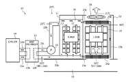
- FIG. 1 is a pattern diagram illustrating an information processing system according to a first embodiment.
- an arrow A indicates a flow direction of cooling water
- arrows B each indicate a flow direction of a refrigerant
- arrows C each indicate a flow direction of air.
- an information processing system 10 includes a liquid immersion tank 11 , an air-cooling tank 12 , a heat exchanger 13 , a chiller 14 , and a pump 15 .
- a space hereinafter, called a “free space 19 ” through which low-temperature air having a temperature managed by a package air conditioner (not illustrated) flows is provided.
- the chiller 14 is installed outside. While, in the present embodiment, the heat exchanger 13 and the pump 15 are installed in the same room as that of the liquid immersion tank 11 and the air-cooling tank 12 , the heat exchanger 13 and the pump 15 may be installed outside.
- a liquid refrigerant 16 is put into the liquid immersion tank 11 .
- Server bricks 17 are immersed in the refrigerant 16 .
- a fluorocarbon compound Fluorinert (registered trademark) manufactured by 3M Company, for example
- oil polyalphaolefin (PAO), for example
- PAO polyalphaolefin
- Refrigerant inlets are provided in a bottom portion of the liquid immersion tank 11 , and a refrigerant outlet is provided in an upper portion thereof. As described later, the low-temperature refrigerant 16 is supplied into the liquid immersion tank 11 by the heat exchanger 13 via the refrigerant inlets. The high-temperature refrigerant 16 in the liquid immersion tank 11 is sucked out from the refrigerant outlet by the pump 15 and is transported to the heat exchanger 13 .
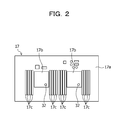
- server bricks 17 each include a board 17 a and electronic components such as central processing units (CPUs) 17 b and memories 17 c mounted in the board 17 a.
- temperature sensors 32 to detect temperatures of electronic components (the CPUs 17 b in the example of FIG. 2 ) are provided.
- each of electronic components such as the CPUs 17 b and the memories 17 c mounted in the board 17 a is an electronic component having high liquid immersion resistance.
- Each of the server bricks 17 is an example of a processing device.
- Each of the CPUs 17 b and the memories 17 c is an example of a first electronic component.
- the air-cooling tank 12 is installed adjacent to the liquid immersion tank 11 .
- Storage bricks 18 are arranged within the air-cooling tank 12 .
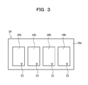
- the storage bricks 18 each include a board 18 a and hard disks 18 b coupled to the board 18 a.
- temperature sensors 33 to detect temperatures of the respective hard disks 18 b are provided.
- a general hard disk in a chassis of which vent holes are provided is used as each of the hard disks 18 b.
- Each of the hard disks 18 b is an example of a second electronic component.
- the server bricks 17 and the storage bricks 18 are electrically coupled by a cable 35 .
- a cooling coil 25 a is arranged in a lower portion of the air-cooling tank 12 , and a cooling coil 25 b is arranged in an upper portion thereof.
- the storage bricks 18 are arranged between the cooling coil 25 a and the cooling coil 25 b.
- a blower 29 is arranged above the cooling coil 25 b. Low-temperature air is introduced from the free space 19 into the air-cooling tank 12 by the blower 29 .
- the position of the blower 29 is not limited to a position located above the cooling coil 25 b and may be a position at which cold air is able to be blown or inhaled into the air-cooling tank 12 .
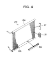
- FIG. 4 is a perspective view illustrating the cooling coil 25 a (reference source: NIKKEI HEAT EXCHANGER COMPANY, LTD., [searched on Sep. 30, 2016], the Internet (URL:http://group.nikkeikin.co.jp/nex/product/post.html)). Since the cooling coil 25 b has the same shape as that of the cooling coil 25 a, an illustration and a description of the cooling coil 25 b will be omitted here.
- the cooling coil 25 a illustrated in FIG. 4 includes two header pipes 26 a and 26 b arranged in parallel to each other, flat pipes 27 for connecting between these header pipes 26 a and 26 b, and corrugated fins 28 arranged between the flat pipes 27 .
- the header pipe 26 a of the cooling coil 25 a is coupled to a lower portion of the liquid immersion tank 11 via a pipe 23 a.
- the header pipe 26 b of the cooling coil 25 a and the header pipe 26 a of the cooling coil 25 b are coupled to each other by a pipe 23 b.
- the header pipe 26 b of the cooling coil 25 b is coupled to an upper portion of the liquid immersion tank 11 via a pipe 23 c.
- the pipes 23 a, 23 b, and 23 c correspond to an example of a refrigerant pipe.
- FIG. 4 illustrates examples of the cooling coils 25 a and 25 b , and the shapes of the cooling coils 25 a and 25 b are not limited to these illustrated in FIG. 4 .
- the cooling coil 25 a in the lower portion of the air-cooling tank 12 may be omitted.
- the heat exchanger 13 includes a cooling water flow path 13 a through which the cooling water flows, and a refrigerant flow path 13 b through which the refrigerant 16 flows.
- An inlet of the cooling water flow path 13 a is coupled to a cooling water outlet of the chiller 14 via a pipe 21 a.
- a cooling water inlet of the chiller 14 is coupled to an outlet of the cooling water flow path 13 a via a pipe 21 b.
- An outlet of the refrigerant flow path 13 b is coupled to the refrigerant inlets of the liquid immersion tank 11 via a pipe 22 a.
- the refrigerant outlet of the liquid immersion tank 11 is coupled to a suction opening (suction) of the pump 15 via a pipe 22 b.
- a discharge opening (delivery) of the pump 15 is coupled to an inlet of the refrigerant flow path 13 b by a pipe 22 c.
- the cooling water circulating between the chiller 14 and the heat exchanger 13 is an example of a primary refrigerant.
- the refrigerant 16 circulating between the heat exchanger 13 and the liquid immersion tank 11 is an example of a secondary refrigerant.
- the pump 15 is an example of a delivery device.
- the chiller 14 is an example of an air-conditioning device to cool the primary refrigerant.
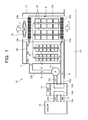
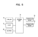
- FIG. 5 is a block diagram illustrating a control system for the information processing system according to the present embodiment.
- the temperature sensors 32 to detect the temperatures of the respective CPUs 17 b are provided in each of the server bricks 17 .
- the temperature sensors 33 to detect the temperatures of the respective hard disks 18 b are provided (see FIG. 2 and FIG. 3 ).
- the control unit 31 controls the temperature of the cooling water supplied by the chiller 14 , the number of rotations of the pump 15 , and the number of rotations of the blower 29 so that temperatures detected by the temperature sensors 32 and the temperature sensors 33 fall within preliminarily set temperature ranges.
- the control unit 31 controls the chiller 14 , thereby changing the temperature or flow rate of the cooling water supplied to the heat exchanger 13 , or controls the pump 15 , thereby changing the flow rate of the refrigerant 16 , for example.
- control unit 31 controls the blower 29 , thereby changing the flow rate of air flowing through the air-cooling tank 12 .
- FIG. 6 illustrates temperatures at respective portions at a time of an operation of the information processing system 10 according to the present embodiment.
- the refrigerant having a temperature of 20° C. is supplied to the liquid immersion tank 11 and the air-cooling tank 12 by the heat exchanger 13 via the pipe 22 a at a flow rate of 180 liters (Ls)/min.
- the power consumption of the server bricks 17 arranged within the liquid immersion tank 11 is 6.4 kW (in total), and the power consumption of the storage bricks 18 arranged within the air-cooling tank 12 is 1.6 kW (in total).
- a flow rate of air caused by the blower 29 to flow through the air-cooling tank 12 is 5 m 3 /min.
- a temperature of the room in which the liquid immersion tank 11 and the air-cooling tank 12 are installed is maintained at 25° C. by the package air conditioner.
- the refrigerant 16 cooled by the heat exchanger 13 at 20° C. is supplied to the liquid immersion tank 11 and the air-cooling tank 12 via the pipe 22 a.
- the server bricks 17 are cooled by the refrigerant 16 supplied via the pipe 22 a. Therefore, temperatures of electronic components (the CPUs 32 and so forth) within the server bricks 17 are maintained at temperatures lower than respective allowable upper-limit temperatures.
- the refrigerant 16 the temperature of which rises due to cooling the server bricks 17 moves upward within the liquid immersion tank 11 .
- the air-cooling tank 12 heat is generated along with operations of the storage bricks 18 , and the temperatures of the respective storage bricks 18 rise.
- air is introduced from the free space 19 by the blower 29 , and the storage bricks 18 are cooled by this air. Therefore, temperatures of electronic components (the hard disks 18 b ) within the storage bricks 18 are maintained at temperatures lower than respective allowable upper-limit temperatures.
- the air introduced from the free space 19 into the air-cooling tank 12 is cooled by the refrigerant 16 flowing through the cooling coil 25 a.
- a temperature of the air after passing through the cooling coil 25 a is 20° C.
- the temperature of the air rises to 36° C.
- the air the temperature of which rises due to cooling the storage bricks 18 is cooled at a time of passing through the cooling coil 25 b and is emitted from the air-cooling tank 12 into the room.
- the temperature of the air at a time of being emitted from the air-cooling tank 12 is 21° C., for example.
- the refrigerant 16 after passing through the cooling coil 25 b enters the liquid immersion tank 11 via the pipe 23 c.
- the refrigerant 16 after passing through the cooling coil 25 b joins the refrigerant 16 that cools the server bricks 17 and moves from the liquid immersion tank 11 to the heat exchanger 13 via the pipe 22 b, the pump 15 , and the pipe 22 c.
- the temperature of the refrigerant 16 passing through the pipe 22 b is 22° C.
- this refrigerant 16 is cooled to 20° C. by the cooling water that flows through the cooling water flow path 13 a.
- the refrigerant 16 is supplied to the liquid immersion tank 11 and the air-cooling tank 12 via the pipe 22 a again.
- a difference ⁇ T (° C.) between the temperature of the refrigerant 16 before cooling the server bricks 17 and the temperature of the refrigerant 16 after cooling the server bricks 17 may be calculated based on the following Expression (1).
- L is a flow rate (liters (Ls)/min) of the refrigerant 16
- C is specific heat (J/kgK) of the refrigerant 16
- ⁇ is a density (kg/m 3 ) of the refrigerant 16 .
- FC-43 Fluorinert
- FC-43 Fluorinert
- a difference ⁇ T (° C.) between the temperature of the air supplied to the air-cooling tank 12 and the temperature of the air emitted from the air-cooling tank 12 may be calculated based on the above-mentioned Expression (1).
- L is a flow rate (liters (Ls)/min) of the air
- C is specific heat (J/kgK) of the air
- ⁇ is a density (kg/m 3 ) of the air.
- the specific heat of the air is 1006 J/kgK, and the density ⁇ thereof is 1.166 kg/m 3 .
- the storage bricks 18 are arranged within the air-cooling tank 12 and are cooled by cold air. Therefore, the general hard disks 18 b in each of which a chassis includes vent holes may be used as storages. Accordingly, a construction cost of the information processing system 10 may be reduced.
- heat generated by the storage bricks 18 in the air-cooling tank 12 is recovered by the refrigerant 16 .
- the refrigerant 16 heat generated by the storage bricks 18 is emitted into the room without change and turns out to be recovered by the package air conditioner.
- the package air conditioner consumes relatively large electric power.
- the cooling coil 25 b recovers the heat generated by the storage bricks 18 . Therefore, a load on the package air conditioner is reduced, and an electric power consumption amount is decreased. Accordingly, compared with a case where no cooling coil 25 b exists, a profound effect on energy saving is achieved.
- the present embodiment since no storage bricks 18 are immersed in the refrigerant 16 , the present embodiment has an advantage that it is easy to perform a maintenance work of the storage bricks 18 .
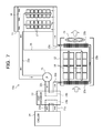
- FIG. 7 is a pattern diagram illustrating an information processing system according to a second embodiment.
- the same symbol is assigned to the same as that in FIG. 1 , and a detailed description thereof will be omitted.
- part of the refrigerant 16 supplied via the pipe 22 a cools the server bricks 17 within the liquid immersion tank 11 .
- a remaining part of the refrigerant 16 cools the storage bricks 18 within the air-cooling tank 12 .
- these refrigerants 16 join and flow through the pipe 22 b. Accordingly, in the first embodiment, it may be said that the liquid immersion tank 11 and the air-cooling tank 12 are coupled in parallel between the pipe 22 a and the pipe 22 b.
- the pipe 22 a is an example of a first pipe.
- the pipe 22 b is an example of a second pipe.
- liquid immersion tank 11 and the air-cooling tank 12 are coupled in series between the pipe 22 a and the pipe 22 b.
- the refrigerant outlet of the heat exchanger 13 and the refrigerant inlet of the cooling coil 25 a of the air-cooling tank 12 are coupled to each other by the pipe 22 a.
- the refrigerant outlet of the cooling coil 25 a and the refrigerant inlet of the cooling coil 25 b are coupled to each other by the pipe 23 b.
- the refrigerant outlet of the cooling coil 25 b and one of the refrigerant inlets of the liquid immersion tank 11 are coupled to each other by the pipe 23 c.
- the refrigerant outlet of the liquid immersion tank 11 and the suction opening (suction) of the pump 15 are coupled to each other by the pipe 22 b.
- the discharge opening (delivery) of the pump 15 and the refrigerant inlet of the heat exchanger 13 are coupled to each other by the pipe 22 c.
- the refrigerant 16 cooled by the heat exchanger 13 is supplied to the air-cooling tank 12 via the pipe 22 a.
- air in the room is introduced from a cooling coil 25 a side into the air-cooling tank 12 by the blower 29 .
- the air introduced into the air-cooling tank 12 is cooled by the refrigerant 16 flowing through the cooling coil 25 a.
- the air-cooling tank 12 heat is generated along with operations of the storage bricks 18 , and the temperatures of the respective storage bricks 18 rise.
- the storage bricks 18 are cooled by the air flowing through the air-cooling tank 12 . Therefore, temperatures of electronic components (the hard disks 18 b ) within the storage bricks 18 are maintained at temperatures lower than the respective allowable upper-limit temperatures.
- the air the temperature of which rises due to cooling the storage bricks 18 is emitted into the room via the cooling coil 25 b.
- the air is cooled by the refrigerant 16 that flows through the cooling coil 25 b. Therefore, the temperature of the air emitted from the air-cooling tank 12 into the room becomes about 21° C., for example.
- the refrigerant 16 after passing through the cooling coil 25 b enters the liquid immersion tank 11 via the pipe 23 c next.
- the liquid immersion tank 11 heat is generated along with operations of the server bricks 17 , and the temperatures of the respective server bricks 17 rise.
- the server bricks 17 are cooled by the refrigerant 16 that moves from the bottom to the top within the liquid immersion tank 11 . Therefore, temperatures of electronic components (the CPUs 32 and so forth) within the server bricks 17 are maintained at temperatures lower than respective allowable upper-limit temperatures.
- the refrigerant 16 the temperature of which rises due to cooling the server bricks 17 returns to the heat exchanger 13 via the pipe 22 b, the pump 15 , and the pipe 22 c.
- the refrigerant 16 is cooled by the cooling water that flows through the cooling water flow path 13 a, and is supplied to the air-cooling tank 12 via the pipe 22 a again.
- the same advantages as those of the first embodiment may be obtained.
- the refrigerant 16 flows in order starting from a tank having a smaller amount of heat generation.
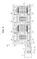
- FIG. 8 is a pattern diagram illustrating an information processing system according to a third embodiment.
- the same symbol is assigned to the same as that in FIG. 1 , and a description of the redundant portion will be omitted.
- an illustration of the cable 35 (see FIG. 1 ) for coupling the server bricks 17 and the storage bricks 18 is omitted.
- the liquid immersion tanks 11 and the air-cooling tanks 12 are included.
- the server bricks 17 are each arranged in a state of being immersed in the refrigerant 16 in each of the liquid immersion tanks 11 , and the storage bricks 18 and the cooling coils 25 a and 25 b are arranged in each of the air-cooling tanks 12 .
- each of the air-cooling tanks 12 In a bottom portion of each of the air-cooling tanks 12 , a hole into the free space 19 is provided, and the corresponding blower 29 supplies low-temperature air from the free space 19 into the relevant air-cooling tank 12 .
- the refrigerant outlet of the heat exchanger 13 is coupled to the pipe 22 a.
- the suction opening of the pump 15 is coupled to the pipe 22 b.
- the discharge opening is coupled to the refrigerant inlet of the heat exchanger 13 via the pipe 22 c.
- a refrigerant inlet provided in a lower portion of each of the liquid immersion tanks 11 is coupled to the pipe 22 a via a pipe 41 a.
- the cooling coil 25 a located on a lower side of each of the air-cooling tanks 12 is coupled to the pipe 22 a via a pipe 41 b.
- the refrigerant outlet located in the upper portion of each of the liquid immersion tanks 11 is coupled to the pipe 22 b via a pipe 42 a.
- the cooling coil 25 b located on an upper side of each of the air-cooling tanks 12 is coupled to the pipe 22 b via a pipe 42 b.
- the liquid immersion tanks 11 and the air-cooling tanks 12 are coupled in parallel between the pipe 22 a and the pipe 22 b.
- the low-temperature refrigerant 16 is supplied to the liquid immersion tanks 11 and the air-cooling tanks 12 via the pipe 22 a, and the high-temperature refrigerant 16 is recovered from the liquid immersion tanks 11 and the air-cooling tanks 12 via the pipe 22 b. For this reason, it is possible to effectively cool the server bricks 17 within each of the liquid immersion tanks 11 and the storage bricks 18 within each of the air-cooling tanks 12 .
- FIG. 9 is a pattern diagram illustrating an example of a modification to the third embodiment.
- vapor of the refrigerant 16 is generated from the liquid immersion tanks 11 .
- the generated vapor enters the hard disks 18 b within the air-cooling tanks 12 and is attached to surfaces of disks. There is a possibility that the attached vapor causes failures of the hard disks 18 b.
- the liquid immersion tanks 11 are arranged in a first room 51
- the air-cooling tanks 12 are arranged in a second room 52 .
- FIG. 10 is a pattern diagram illustrating an information processing system according to a fourth embodiment.
- the same symbol is assigned to the same as that in FIG. 1 , and a description of the redundant portion will be omitted.
- an illustration of the cable 35 (see FIG. 1 ) for coupling the server bricks 17 and the storage bricks 18 is omitted.
- the server bricks 17 and power supply units (PSUs) 55 are immersed in the refrigerant 16 within the liquid immersion tank 11 .
- the PSUs 55 supplies electric power to the server bricks 17 and the storage bricks 18 within air-cooling tank 12 .
- the PSUs 55 each generate heat along with an operation thereof. In a case where the amount of heat generation of the PSUs 55 is large, it is desirable that the PSUs 55 are arranged within the liquid immersion tank 11 and are cooled by the refrigerant 16 in the same way as in the present embodiment.
- the PSUs 55 may be arranged within the air-cooling tank 12 .
- the PSU 55 may be arranged in each of the liquid immersion tank 11 and the air-cooling tank 12 , the PSU 55 within the liquid immersion tank 11 may supply electric power to the server bricks 17 within the liquid immersion tank 11 , and the PSU 55 within the air-cooling tank 12 may supply electric power to the storage bricks 18 within the air-cooling tank 12 .
Landscapes
- Engineering & Computer Science (AREA)
- Microelectronics & Electronic Packaging (AREA)
- Physics & Mathematics (AREA)
- Thermal Sciences (AREA)
- Computer Hardware Design (AREA)
- General Engineering & Computer Science (AREA)
- Cooling Or The Like Of Electrical Apparatus (AREA)
- Cooling Or The Like Of Semiconductors Or Solid State Devices (AREA)
Abstract
Description
- This application is based upon and claims the benefit of priority of the prior Japanese Patent Application No. 2016-196381, filed on Oct. 4, 2016, the entire contents of which are incorporated herein by reference.
- The embodiments discussed herein are related to an information processing system and a control method for the information processing system.
- In recent years, it has been desirable that electronic devices such as servers or storages are densely implemented in a data center. On the other hand, the amount of heat generation of the electronic devices has increased with an increase in speed of the electronic devices.
- In a case where electronic devices each having a large amount of heat generation are densely implemented, temperatures of the electronic devices exceed allowable upper-limit temperatures and cause an incorrect operation or a failure. Therefore, cooling methods each capable of fully cooling electronic devices each having a large amount of heat generation even in a case where the electronic devices are densely implemented are requested.
- As one of such cooling methods, it is proposed that an electronic device is immersed in a liquid refrigerant and is cooled. Hereinafter, this type of cooling method will be called a liquid immersion cooling method. In the liquid immersion cooling method, an inactive liquid refrigerant having a high insulation property (a fluorocarbon compound, for example) is put into a liquid immersion tank, and an electronic device is immersed in the refrigerant, thereby circulating the refrigerant between the liquid immersion tank and a heat exchanger.
- In the liquid immersion cooling method, it is proposed that an electronic device having a large amount of heat generation and an electronic device having a small amount of heat generation are immersed in refrigerants of respective different liquid immersion tanks (see, for example, Japanese Laid-open Patent Publication No. 5-160310 and so forth). Furthermore, it is proposed that a heat sink is attached to an element having a large amount of heat generation and the relevant heat sink is cooled by a dielectric coolant (see, for example, Japanese National Publication of International Patent Application No. 2011-518395 and so forth).
- In general, in an information processing system, hard disks are used as external storage devices. Each of general hard disks is designed on the premise of being used in the atmosphere, and in a chassis thereof, vent holes for connecting between a space within the chassis and the outside thereof are provided. The reason is that an increase in pressure within the chassis, caused by heat generated along with an operation, is kept from deteriorating both a write characteristic and a read characteristic.
- In a case where this type of hard disk is immersive in a refrigerant, the refrigerant enters the chassis from the vent holes, and surfaces of disks are covered by the refrigerant, thereby disabling reading and writing of data. Accordingly, it is difficult for this type of hard disk to be immersed in the refrigerant and to be used. This type of hard disk is an example of electronic components each having low liquid immersion resistance.
- It is conceivable that, as a storage, a solid stare drive (SSD) or a hard disk filled with helium gas (hereinafter, called a He-filled hard disk drive (HDD)) is used. Since being hermetically sealed, the SSD and the He-filled HDD each have high liquid immersion resistance and are able to be immersed in the refrigerant and be used.
- However, the SSD and the He-filled HDD have high production costs, compared with the above-mentioned general hard disks. Many storages are used in the data center. Therefore, in a case of using the SSDs or the He-filled HDDs, a construction cost of the information processing system is greatly elevated. In view of the above, it is desirable that, by using a liquid refrigerant, it is possible to cool an electronic component having low liquid immersion resistance in addition to an electronic component having high liquid immersion resistance.
- According to an aspect of the invention, an information processing system includes a chiller configured to cool a primary refrigerant; a liquid immersion tank in which a processing device including a first electronic component is immersed in a secondary refrigerant; a second electronic component coupled to the processing device; a blower configured to blow or inhale air for the second electronic component; a coil in which the secondary refrigerant is cooled by the air; an air tank that is coupled to the coil and that includes a refrigerant pipe through which the secondary refrigerant flows; a heat exchanger configured to exchange heat between the primary refrigerant and the secondary refrigerant; and a pump configured to circulate the secondary refrigerant from the liquid immersion tank to the heat exchanger.
- The object and advantages of the invention will be realized and attained by means of the elements and combinations particularly pointed out in the claims.
- It is to be understood that both the foregoing general description and the following detailed description are exemplary and explanatory and are not restrictive of the invention, as claimed.
-
FIG. 1 is a pattern diagram illustrating an information processing system according to a first embodiment; -
FIG. 2 is a schematic plan view illustrating a server brick; -
FIG. 3 is a schematic plan view illustrating a storage brick; -
FIG. 4 is a perspective view illustrating a cooling coil; -
FIG. 5 is a block diagram illustrating a control system for the information processing system according to the first embodiment; -
FIG. 6 is a diagram illustrating temperatures at respective portions at a time of an operation of the information processing system according to the first embodiment; -
FIG. 7 is a pattern diagram illustrating an information processing system according to a second embodiment; -
FIG. 8 is a pattern diagram illustrating an information processing system according to a third embodiment; -
FIG. 9 is a pattern diagram illustrating an example of a modification to the third embodiment; and -
FIG. 10 is a pattern diagram illustrating an information processing system according to a fourth embodiment. - Hereinafter, embodiments will be described with reference to attached drawings.
-
FIG. 1 is a pattern diagram illustrating an information processing system according to a first embodiment. InFIG. 1 , an arrow A indicates a flow direction of cooling water, arrows B each indicate a flow direction of a refrigerant, and arrows C each indicate a flow direction of air. - As illustrated in
FIG. 1 , aninformation processing system 10 according to the present embodiment includes aliquid immersion tank 11, an air-cooling tank 12, aheat exchanger 13, achiller 14, and apump 15. Under the floor of a room in which theliquid immersion tank 11 and the air-cooling tank 12 are installed, a space (hereinafter, called a “free space 19”) through which low-temperature air having a temperature managed by a package air conditioner (not illustrated) flows is provided. - The
chiller 14 is installed outside. While, in the present embodiment, theheat exchanger 13 and thepump 15 are installed in the same room as that of theliquid immersion tank 11 and the air-cooling tank 12, theheat exchanger 13 and thepump 15 may be installed outside. - A
liquid refrigerant 16 is put into theliquid immersion tank 11.Server bricks 17 are immersed in therefrigerant 16. As therefrigerant 16, a fluorocarbon compound (Fluorinert (registered trademark) manufactured by 3M Company, for example), oil (polyalphaolefin (PAO), for example), or the like may be used. - Refrigerant inlets are provided in a bottom portion of the
liquid immersion tank 11, and a refrigerant outlet is provided in an upper portion thereof. As described later, the low-temperature refrigerant 16 is supplied into theliquid immersion tank 11 by theheat exchanger 13 via the refrigerant inlets. The high-temperature refrigerant 16 in theliquid immersion tank 11 is sucked out from the refrigerant outlet by thepump 15 and is transported to theheat exchanger 13. - As illustrated in
FIG. 2 ,server bricks 17 each include aboard 17 a and electronic components such as central processing units (CPUs) 17 b andmemories 17 c mounted in theboard 17 a. In each of theserver bricks 17,temperature sensors 32 to detect temperatures of electronic components (theCPUs 17 b in the example ofFIG. 2 ) are provided. Here, each of electronic components such as theCPUs 17 b and thememories 17 c mounted in theboard 17 a is an electronic component having high liquid immersion resistance. Each of theserver bricks 17 is an example of a processing device. Each of theCPUs 17 b and thememories 17 c is an example of a first electronic component. - The air-
cooling tank 12 is installed adjacent to theliquid immersion tank 11.Storage bricks 18 are arranged within the air-cooling tank 12. - As illustrated in
FIG. 3 , thestorage bricks 18 each include aboard 18 a andhard disks 18 b coupled to theboard 18 a. In each of thestorage bricks 18,temperature sensors 33 to detect temperatures of the respectivehard disks 18 b are provided. In the present embodiment, as each of thehard disks 18 b, a general hard disk in a chassis of which vent holes are provided is used. Each of thehard disks 18 b is an example of a second electronic component. - The
server bricks 17 and the storage bricks 18 (thehard disks 18 b) are electrically coupled by acable 35. - In a bottom portion of the air-
cooling tank 12, a hole into thefree space 19 is provided as illustrated inFIG. 1 . A coolingcoil 25 a is arranged in a lower portion of the air-cooling tank 12, and a coolingcoil 25 b is arranged in an upper portion thereof. Thestorage bricks 18 are arranged between the coolingcoil 25 a and the coolingcoil 25 b. - A
blower 29 is arranged above the coolingcoil 25 b. Low-temperature air is introduced from thefree space 19 into the air-cooling tank 12 by theblower 29. The position of theblower 29 is not limited to a position located above the coolingcoil 25 b and may be a position at which cold air is able to be blown or inhaled into the air-cooling tank 12. -
FIG. 4 is a perspective view illustrating the coolingcoil 25 a (reference source: NIKKEI HEAT EXCHANGER COMPANY, LTD., [searched on Sep. 30, 2016], the Internet (URL:http://group.nikkeikin.co.jp/nex/product/post.html)). Since the coolingcoil 25 b has the same shape as that of the coolingcoil 25 a, an illustration and a description of the coolingcoil 25 b will be omitted here. - The cooling
coil 25 a illustrated inFIG. 4 includes twoheader pipes flat pipes 27 for connecting between theseheader pipes corrugated fins 28 arranged between theflat pipes 27. - As illustrated in
FIG. 1 , theheader pipe 26 a of the coolingcoil 25 a, arranged in a lower portion of the air-cooling tank 12, is coupled to a lower portion of theliquid immersion tank 11 via apipe 23 a. Theheader pipe 26 b of the coolingcoil 25 a and theheader pipe 26 a of the coolingcoil 25 b are coupled to each other by apipe 23 b. Theheader pipe 26 b of the coolingcoil 25 b is coupled to an upper portion of theliquid immersion tank 11 via apipe 23 c. - The
pipes FIG. 4 illustrates examples of the cooling coils 25 a and 25 b, and the shapes of the cooling coils 25 a and 25 b are not limited to these illustrated inFIG. 4 . In a case where the package air conditioner or the like supplies, to thefree space 19, air having a managed temperature, the coolingcoil 25 a in the lower portion of the air-cooling tank 12 may be omitted. - As illustrated in
FIG. 1 , theheat exchanger 13 includes a coolingwater flow path 13 a through which the cooling water flows, and arefrigerant flow path 13 b through which the refrigerant 16 flows. - An inlet of the cooling
water flow path 13 a is coupled to a cooling water outlet of thechiller 14 via apipe 21 a. A cooling water inlet of thechiller 14 is coupled to an outlet of the coolingwater flow path 13 a via apipe 21 b. An outlet of therefrigerant flow path 13 b is coupled to the refrigerant inlets of theliquid immersion tank 11 via apipe 22 a. Furthermore, the refrigerant outlet of theliquid immersion tank 11 is coupled to a suction opening (suction) of thepump 15 via apipe 22 b. A discharge opening (delivery) of thepump 15 is coupled to an inlet of therefrigerant flow path 13 b by apipe 22 c. - In the present embodiment, the cooling water circulating between the
chiller 14 and theheat exchanger 13 is an example of a primary refrigerant. The refrigerant 16 circulating between theheat exchanger 13 and theliquid immersion tank 11 is an example of a secondary refrigerant. Thepump 15 is an example of a delivery device. Thechiller 14 is an example of an air-conditioning device to cool the primary refrigerant. -
FIG. 5 is a block diagram illustrating a control system for the information processing system according to the present embodiment. - As described above, in each of the
server bricks 17, thetemperature sensors 32 to detect the temperatures of therespective CPUs 17 b are provided. In each of thestorage bricks 18, thetemperature sensors 33 to detect the temperatures of the respectivehard disks 18 b are provided (seeFIG. 2 andFIG. 3 ). - The
control unit 31 controls the temperature of the cooling water supplied by thechiller 14, the number of rotations of thepump 15, and the number of rotations of theblower 29 so that temperatures detected by thetemperature sensors 32 and thetemperature sensors 33 fall within preliminarily set temperature ranges. - In a case where the temperature of one of the
server bricks 17, detected by the correspondingtemperature sensor 32, does not fall within a setting range, thecontrol unit 31 controls thechiller 14, thereby changing the temperature or flow rate of the cooling water supplied to theheat exchanger 13, or controls thepump 15, thereby changing the flow rate of the refrigerant 16, for example. - In a case where the temperature of one of the
storage bricks 18, detected by the correspondingtemperature sensor 33, does not fall within a setting range, thecontrol unit 31 controls theblower 29, thereby changing the flow rate of air flowing through the air-cooling tank 12. - Hereinafter, an operation of the
information processing system 10 will be described with reference toFIG. 6 .FIG. 6 illustrates temperatures at respective portions at a time of an operation of theinformation processing system 10 according to the present embodiment. - As illustrated in
FIG. 6 , the refrigerant having a temperature of 20° C. is supplied to theliquid immersion tank 11 and the air-cooling tank 12 by theheat exchanger 13 via thepipe 22 a at a flow rate of 180 liters (Ls)/min. The power consumption of theserver bricks 17 arranged within theliquid immersion tank 11 is 6.4 kW (in total), and the power consumption of thestorage bricks 18 arranged within the air-cooling tank 12 is 1.6 kW (in total). A flow rate of air caused by theblower 29 to flow through the air-cooling tank 12 is 5 m3/min. Furthermore, a temperature of the room in which theliquid immersion tank 11 and the air-cooling tank 12 are installed is maintained at 25° C. by the package air conditioner. - As illustrated in
FIG. 6 , the refrigerant 16 cooled by theheat exchanger 13 at 20° C. is supplied to theliquid immersion tank 11 and the air-cooling tank 12 via thepipe 22 a. - In the
liquid immersion tank 11, heat is generated along with operations of theserver bricks 17, and the temperatures of therespective server bricks 17 rise. However, theserver bricks 17 are cooled by the refrigerant 16 supplied via thepipe 22 a. Therefore, temperatures of electronic components (theCPUs 32 and so forth) within theserver bricks 17 are maintained at temperatures lower than respective allowable upper-limit temperatures. The refrigerant 16 the temperature of which rises due to cooling theserver bricks 17 moves upward within theliquid immersion tank 11. - On the other hand, in the air-
cooling tank 12, heat is generated along with operations of thestorage bricks 18, and the temperatures of therespective storage bricks 18 rise. However, in the air-cooling tank 12, air is introduced from thefree space 19 by theblower 29, and thestorage bricks 18 are cooled by this air. Therefore, temperatures of electronic components (thehard disks 18 b) within thestorage bricks 18 are maintained at temperatures lower than respective allowable upper-limit temperatures. - At a time of passing through the cooling
coil 25 a, the air introduced from thefree space 19 into the air-cooling tank 12 is cooled by the refrigerant 16 flowing through the coolingcoil 25 a. Here, it is assumed that a temperature of the air after passing through the coolingcoil 25 a is 20° C. By cooling thestorage bricks 18, the temperature of the air rises to 36° C. - The air the temperature of which rises due to cooling the
storage bricks 18 is cooled at a time of passing through the coolingcoil 25 b and is emitted from the air-cooling tank 12 into the room. The temperature of the air at a time of being emitted from the air-cooling tank 12 is 21° C., for example. - On the other hand, the refrigerant 16 after passing through the cooling
coil 25 b enters theliquid immersion tank 11 via thepipe 23 c. In addition, the refrigerant 16 after passing through the coolingcoil 25 b joins the refrigerant 16 that cools theserver bricks 17 and moves from theliquid immersion tank 11 to theheat exchanger 13 via thepipe 22 b, thepump 15, and thepipe 22 c. Here, it is assumed that the temperature of the refrigerant 16 passing through thepipe 22 b is 22° C. - Within the
heat exchanger 13, this refrigerant 16 is cooled to 20° C. by the cooling water that flows through the coolingwater flow path 13 a. In addition, the refrigerant 16 is supplied to theliquid immersion tank 11 and the air-cooling tank 12 via thepipe 22 a again. - A difference ΔT (° C.) between the temperature of the refrigerant 16 before cooling the
server bricks 17 and the temperature of the refrigerant 16 after cooling theserver bricks 17 may be calculated based on the following Expression (1). -
ΔT=W×60×103/(L×ρ×C) (1) - In this regard, however, “W” is the amount of heat generation (=power consumption (W)) of the
server bricks 17, “L” is a flow rate (liters (Ls)/min) of the refrigerant 16, “C” is specific heat (J/kgK) of the refrigerant 16, and “ρ” is a density (kg/m3) of the refrigerant 16. In a case of Fluorinert (FC-43) of 3M Company, the specific heat C is 1050 J/kgK, and the density ρ is 1880 kg/m3. - A difference ΔT (° C.) between the temperature of the air supplied to the air-
cooling tank 12 and the temperature of the air emitted from the air-cooling tank 12 may be calculated based on the above-mentioned Expression (1). - In this regard, however, “W” is the amount of heat generation (=power consumption (W)) of
storage bricks 18, “L” is a flow rate (liters (Ls)/min) of the air, “C” is specific heat (J/kgK) of the air, and “ρ” is a density (kg/m3) of the air. The specific heat of the air is 1006 J/kgK, and the density ρ thereof is 1.166 kg/m3. - Hereinafter, advantages of the present embodiment will be described.
- In the present embodiment, the
storage bricks 18 are arranged within the air-cooling tank 12 and are cooled by cold air. Therefore, the generalhard disks 18 b in each of which a chassis includes vent holes may be used as storages. Accordingly, a construction cost of theinformation processing system 10 may be reduced. - Since no
storage bricks 18 are arranged in theliquid immersion tank 11, it is possible to reduce the volume of theliquid immersion tank 11 at that rate. In general, a refrigerant used for the liquid immersion cooling method is expensive. Therefore, by reducing a usage amount of the refrigerant, it is possible to further reduce the construction cost of theinformation processing system 10 and to reduce a running cost. - Furthermore, in the present embodiment, heat generated by the
storage bricks 18 in the air-cooling tank 12 is recovered by the refrigerant 16. If no coolingcoil 25 b exists, heat generated by thestorage bricks 18 is emitted into the room without change and turns out to be recovered by the package air conditioner. In that case, in order to recover the heat generated by thestorage bricks 18, the package air conditioner consumes relatively large electric power. On the other hand, in the present embodiment, the coolingcoil 25 b recovers the heat generated by thestorage bricks 18. Therefore, a load on the package air conditioner is reduced, and an electric power consumption amount is decreased. Accordingly, compared with a case where no coolingcoil 25 b exists, a profound effect on energy saving is achieved. - Furthermore, since no
storage bricks 18 are immersed in the refrigerant 16, the present embodiment has an advantage that it is easy to perform a maintenance work of thestorage bricks 18. -
FIG. 7 is a pattern diagram illustrating an information processing system according to a second embodiment. InFIG. 7 , the same symbol is assigned to the same as that inFIG. 1 , and a detailed description thereof will be omitted. - In the first embodiment illustrated in
FIG. 1 , part of the refrigerant 16 supplied via thepipe 22 a cools theserver bricks 17 within theliquid immersion tank 11. In addition, a remaining part of the refrigerant 16 cools thestorage bricks 18 within the air-cooling tank 12. In addition, theserefrigerants 16 join and flow through thepipe 22 b. Accordingly, in the first embodiment, it may be said that theliquid immersion tank 11 and the air-cooling tank 12 are coupled in parallel between thepipe 22 a and thepipe 22 b. Thepipe 22 a is an example of a first pipe. Thepipe 22 b is an example of a second pipe. - In contrast, in the second embodiment, the
liquid immersion tank 11 and the air-cooling tank 12 are coupled in series between thepipe 22 a and thepipe 22 b. - In other words, as illustrated in
FIG. 7 , in aninformation processing system 10 a according to the present embodiment, the refrigerant outlet of theheat exchanger 13 and the refrigerant inlet of the coolingcoil 25 a of the air-cooling tank 12 are coupled to each other by thepipe 22 a. The refrigerant outlet of the coolingcoil 25 a and the refrigerant inlet of the coolingcoil 25 b are coupled to each other by thepipe 23 b. The refrigerant outlet of the coolingcoil 25 b and one of the refrigerant inlets of theliquid immersion tank 11 are coupled to each other by thepipe 23 c. - Furthermore, the refrigerant outlet of the
liquid immersion tank 11 and the suction opening (suction) of thepump 15 are coupled to each other by thepipe 22 b. The discharge opening (delivery) of thepump 15 and the refrigerant inlet of theheat exchanger 13 are coupled to each other by thepipe 22 c. - Hereinafter, an operation of the
information processing system 10 a according to the present embodiment will be described. - The refrigerant 16 cooled by the
heat exchanger 13 is supplied to the air-cooling tank 12 via thepipe 22 a. - In the air-
cooling tank 12, air in the room is introduced from a coolingcoil 25 a side into the air-cooling tank 12 by theblower 29. At a time of passing through the coolingcoil 25 a, the air introduced into the air-cooling tank 12 is cooled by the refrigerant 16 flowing through the coolingcoil 25 a. - In the air-
cooling tank 12, heat is generated along with operations of thestorage bricks 18, and the temperatures of therespective storage bricks 18 rise. However, thestorage bricks 18 are cooled by the air flowing through the air-cooling tank 12. Therefore, temperatures of electronic components (thehard disks 18 b) within thestorage bricks 18 are maintained at temperatures lower than the respective allowable upper-limit temperatures. - The air the temperature of which rises due to cooling the
storage bricks 18 is emitted into the room via the coolingcoil 25 b. At a time when the air passes through the coolingcoil 25 b, the air is cooled by the refrigerant 16 that flows through the coolingcoil 25 b. Therefore, the temperature of the air emitted from the air-cooling tank 12 into the room becomes about 21° C., for example. - On the other hand, the refrigerant 16 after passing through the cooling
coil 25 b enters theliquid immersion tank 11 via thepipe 23 c next. In theliquid immersion tank 11, heat is generated along with operations of theserver bricks 17, and the temperatures of therespective server bricks 17 rise. However, theserver bricks 17 are cooled by the refrigerant 16 that moves from the bottom to the top within theliquid immersion tank 11. Therefore, temperatures of electronic components (theCPUs 32 and so forth) within theserver bricks 17 are maintained at temperatures lower than respective allowable upper-limit temperatures. - The refrigerant 16 the temperature of which rises due to cooling the
server bricks 17 returns to theheat exchanger 13 via thepipe 22 b, thepump 15, and thepipe 22 c. The refrigerant 16 is cooled by the cooling water that flows through the coolingwater flow path 13 a, and is supplied to the air-cooling tank 12 via thepipe 22 a again. - In the present embodiment, the same advantages as those of the first embodiment may be obtained. In a case of coupling tanks (the
liquid immersion tank 11 and the air-cooling tank 12) in series like the present embodiment, it is desirable that the refrigerant 16 flows in order starting from a tank having a smaller amount of heat generation. -
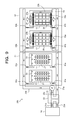
FIG. 8 is a pattern diagram illustrating an information processing system according to a third embodiment. InFIG. 8 , the same symbol is assigned to the same as that inFIG. 1 , and a description of the redundant portion will be omitted. InFIG. 8 , an illustration of the cable 35 (seeFIG. 1 ) for coupling theserver bricks 17 and thestorage bricks 18 is omitted. - In an
information processing system 10 b illustrated inFIG. 8 , theliquid immersion tanks 11 and the air-cooling tanks 12 are included. Theserver bricks 17 are each arranged in a state of being immersed in the refrigerant 16 in each of theliquid immersion tanks 11, and thestorage bricks 18 and the cooling coils 25 a and 25 b are arranged in each of the air-cooling tanks 12. - In a bottom portion of each of the air-
cooling tanks 12, a hole into thefree space 19 is provided, and thecorresponding blower 29 supplies low-temperature air from thefree space 19 into the relevant air-cooling tank 12. - In the same way as in the first embodiment, the refrigerant outlet of the
heat exchanger 13 is coupled to thepipe 22 a. The suction opening of thepump 15 is coupled to thepipe 22 b. The discharge opening is coupled to the refrigerant inlet of theheat exchanger 13 via thepipe 22 c. - A refrigerant inlet provided in a lower portion of each of the
liquid immersion tanks 11 is coupled to thepipe 22 a via apipe 41 a. The coolingcoil 25 a located on a lower side of each of the air-cooling tanks 12 is coupled to thepipe 22 a via apipe 41 b. Furthermore, the refrigerant outlet located in the upper portion of each of theliquid immersion tanks 11 is coupled to thepipe 22 b via apipe 42 a. The coolingcoil 25 b located on an upper side of each of the air-cooling tanks 12 is coupled to thepipe 22 b via apipe 42 b. - In the present embodiment, the
liquid immersion tanks 11 and the air-cooling tanks 12 are coupled in parallel between thepipe 22 a and thepipe 22 b. In addition, the low-temperature refrigerant 16 is supplied to theliquid immersion tanks 11 and the air-cooling tanks 12 via thepipe 22 a, and the high-temperature refrigerant 16 is recovered from theliquid immersion tanks 11 and the air-cooling tanks 12 via thepipe 22 b. For this reason, it is possible to effectively cool theserver bricks 17 within each of theliquid immersion tanks 11 and thestorage bricks 18 within each of the air-cooling tanks 12. -
FIG. 9 is a pattern diagram illustrating an example of a modification to the third embodiment. - In a case where the
liquid immersion tanks 11 and the air-cooling tanks 12 are arranged in the same room, vapor of the refrigerant 16 is generated from theliquid immersion tanks 11. In addition, the generated vapor enters thehard disks 18 b within the air-cooling tanks 12 and is attached to surfaces of disks. There is a possibility that the attached vapor causes failures of thehard disks 18 b. - In an
information processing system 10 c illustrated inFIG. 9 , theliquid immersion tanks 11 are arranged in afirst room 51, and the air-cooling tanks 12 are arranged in asecond room 52. - In other words, in the example of a modification illustrated in
FIG. 9 , a space in which theliquid immersion tanks 11 are arranged and a space in which the air-cooling tanks 12 are arranged are physically separated. For this reason, it is possible to avoid failures of thehard disks 18 b, caused by the vapor of the refrigerant 16. -
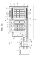
FIG. 10 is a pattern diagram illustrating an information processing system according to a fourth embodiment. InFIG. 10 , the same symbol is assigned to the same as that inFIG. 1 , and a description of the redundant portion will be omitted. InFIG. 10 , an illustration of the cable 35 (seeFIG. 1 ) for coupling theserver bricks 17 and thestorage bricks 18 is omitted. - In an
information processing system 10 d according to the present embodiment, theserver bricks 17 and power supply units (PSUs) 55 are immersed in the refrigerant 16 within theliquid immersion tank 11. In addition, by usingcables 36, thePSUs 55 supplies electric power to theserver bricks 17 and thestorage bricks 18 within air-cooling tank 12. - The
PSUs 55 each generate heat along with an operation thereof. In a case where the amount of heat generation of thePSUs 55 is large, it is desirable that thePSUs 55 are arranged within theliquid immersion tank 11 and are cooled by the refrigerant 16 in the same way as in the present embodiment. - In a case where the amount of heat generation of the
PSUs 55 is not so large, thePSUs 55 may be arranged within the air-cooling tank 12. ThePSU 55 may be arranged in each of theliquid immersion tank 11 and the air-cooling tank 12, thePSU 55 within theliquid immersion tank 11 may supply electric power to theserver bricks 17 within theliquid immersion tank 11, and thePSU 55 within the air-cooling tank 12 may supply electric power to thestorage bricks 18 within the air-cooling tank 12. - All examples and conditional language recited herein are intended for pedagogical purposes to aid the reader in understanding the invention and the concepts contributed by the inventor to furthering the art, and are to be construed as being without limitation to such specifically recited examples and conditions, nor does the organization of such examples in the specification relate to a showing of the superiority and inferiority of the invention. Although the embodiments of the present invention have been described in detail, it should be understood that the various changes, substitutions, and alterations could be made hereto without departing from the spirit and scope of the invention.
Claims (14)
Applications Claiming Priority (2)
| Application Number | Priority Date | Filing Date | Title |
|---|---|---|---|
| JP2016196381A JP6790690B2 (en) | 2016-10-04 | 2016-10-04 | Information processing system and control method of information processing system |
| JP2016-196381 | 2016-10-04 |
Publications (2)
| Publication Number | Publication Date |
|---|---|
| US20180098464A1 true US20180098464A1 (en) | 2018-04-05 |
| US10064313B2 US10064313B2 (en) | 2018-08-28 |
Family
ID=61759236
Family Applications (1)
| Application Number | Title | Priority Date | Filing Date |
|---|---|---|---|
| US15/712,191 Active US10064313B2 (en) | 2016-10-04 | 2017-09-22 | Information processing system and control method for information processing system |
Country Status (2)
| Country | Link |
|---|---|
| US (1) | US10064313B2 (en) |
| JP (1) | JP6790690B2 (en) |
Cited By (23)
| Publication number | Priority date | Publication date | Assignee | Title |
|---|---|---|---|---|
| US20190297754A1 (en) * | 2019-06-14 | 2019-09-26 | Intel Corporation | Liquid cooling system with sub atmospheric pressure coolant |
| US20190327862A1 (en) * | 2018-04-23 | 2019-10-24 | Dell Products, L.P. | Closed-loop supplemental heater system in an air handler system of outside air cooled data center |
| US10481650B2 (en) * | 2015-11-16 | 2019-11-19 | Exascaler Inc. | Electronic device for liquid immersion cooling and cooling system using the same |
| US20190394908A1 (en) * | 2018-06-22 | 2019-12-26 | Cpt Group Gmbh | Arrangement having a housing and a power electronics circuit arranged on a housing base in the housing |
| CN110691490A (en) * | 2018-07-05 | 2020-01-14 | 百度(美国)有限责任公司 | Immersion cooling system for data center |
| US10617031B2 (en) * | 2018-06-13 | 2020-04-07 | Fujitsu Limited | Electronic device |
| US10750637B1 (en) * | 2019-10-24 | 2020-08-18 | Microsoft Technology Licensing, Llc | Immersion cooling infrastructure module having compute device form factor |
| US20200383237A1 (en) * | 2019-05-31 | 2020-12-03 | Fujitsu Limited | Immersion system |
| US10925180B2 (en) * | 2019-03-04 | 2021-02-16 | Baidu Usa Llc | IT container system design approach for fast deployment and high compatibility application scenarios |
| CN114698350A (en) * | 2022-04-28 | 2022-07-01 | 阿里巴巴(中国)有限公司 | Immersion liquid cooling system and control method, equipment, storage medium, program product |
| WO2022162174A1 (en) * | 2021-01-29 | 2022-08-04 | Solo30 B.V. | Hybrid datacentre module |
| US11432436B2 (en) * | 2019-08-19 | 2022-08-30 | Jason Todd Roth | Data center cooling system and related methods |
| WO2022240520A1 (en) * | 2021-05-13 | 2022-11-17 | Microsoft Technology Licensing, Llc | Immersion cooling system that enables increased heat flux at heat-generating components of computing devices |
| US11516943B2 (en) * | 2017-12-26 | 2022-11-29 | Inpro Technologies Limited Liability Company | Direct liquid cooling system for cooling of electronic components |
| US20230413473A1 (en) * | 2022-06-16 | 2023-12-21 | META Green Cooling Technology Co., Ltd. | Single-phase immersion cooling system |
| US20240107709A1 (en) * | 2022-09-23 | 2024-03-28 | Luxshare Thermal Technologies (Huizhou) Co., Ltd | Immersed cabinet and heat dissipation system thereof |
| US20240130091A1 (en) * | 2019-08-23 | 2024-04-18 | Microsoft Technology Licensing, Llc | Mitigating vapor loss in a two-phase immersion cooling system |
| WO2024098110A1 (en) * | 2022-11-10 | 2024-05-16 | Firmus Metal Technologies Singapore Pte Ltd | Systems for cooling of computing devices using liquid immersion |
| EP4432798A1 (en) * | 2023-03-16 | 2024-09-18 | Ovh | Hybrid cooling arrangement for autonomous and immersion cooled racks |
| TWI877032B (en) * | 2024-06-13 | 2025-03-11 | 英業達股份有限公司 | Server and server liquid cooling system |
| EP4576961A1 (en) * | 2023-12-22 | 2025-06-25 | Ovh | Prioritized liquid cooling arrangements for datacenter server racks |
| US12363865B2 (en) | 2022-01-28 | 2025-07-15 | The Research Foundation For The State University Of New York | Regenerative preheater for phase change cooling applications |
| US12426208B2 (en) | 2021-11-22 | 2025-09-23 | Google Llc | Modular liquid cooling architecture for liquid cooling |
Families Citing this family (13)
| Publication number | Priority date | Publication date | Assignee | Title |
|---|---|---|---|---|
| JP6888469B2 (en) * | 2017-08-04 | 2021-06-16 | 富士通株式会社 | Information processing device |
| CN108882658B (en) * | 2018-09-07 | 2024-05-24 | 中南大学 | Server cabinet cooling system combining immersion liquid cooling and circulating air cooling |
| KR20250099407A (en) * | 2018-11-16 | 2025-07-01 | 모딘 엘엘씨 | Liquid immersion cooling platform |
| US10966349B1 (en) * | 2020-07-27 | 2021-03-30 | Bitfury Ip B.V. | Two-phase immersion cooling apparatus with active vapor management |
| US12317450B1 (en) | 2021-11-08 | 2025-05-27 | Rhodium Technologies LLC | Fluid circulation systems and methods for cooling having a collector |
| TWI804372B (en) * | 2022-06-30 | 2023-06-01 | 緯穎科技服務股份有限公司 | Rerouting device, immersion cooling system having the same, and fluid separation method of the immersion cooling system |
| EP4152907A1 (en) * | 2022-08-26 | 2023-03-22 | Ovh | Hybrid liquid cooling arrangement for autonomous and immersion cooled racks |
| CN115666112B (en) * | 2022-12-22 | 2023-04-11 | 苏州浪潮智能科技有限公司 | Immersion liquid cooling system, method and server |
| WO2026013730A1 (en) * | 2024-07-08 | 2026-01-15 | 株式会社Zyrq | Cooling method for computer system, and cooling system |
| US12256518B1 (en) | 2024-07-16 | 2025-03-18 | Frontier Communications Holdings, Llc | Submersible networking enclosure |
| US12349310B1 (en) | 2024-07-16 | 2025-07-01 | Frontier Communications Holdings, Llc | Submersible networking enclosure |
| US12464685B1 (en) * | 2024-07-16 | 2025-11-04 | Frontier Communications Holdings, Llc | Submersible networking enclosure |
| US12326765B1 (en) | 2024-07-16 | 2025-06-10 | Frontier Communications Holdings, Llc | Submersible networking enclosure |
Citations (11)
| Publication number | Priority date | Publication date | Assignee | Title |
|---|---|---|---|---|
| US5099651A (en) * | 1989-09-05 | 1992-03-31 | Gas Research Institute | Gas engine driven heat pump method |
| US20030042361A1 (en) * | 2001-09-05 | 2003-03-06 | George Simadiris | Liquid galley refrigeration system for aircraft |
| US20110271695A1 (en) * | 2010-05-06 | 2011-11-10 | Hitachi Plant Technologies, Ltd. | Cooling method and cooling system for electronic device |
| US20130021746A1 (en) * | 2011-07-21 | 2013-01-24 | International Business Machines Corporation | Data center cooling with an air-side economizer and liquid-cooled electronics rack(s) |
| US20140218858A1 (en) * | 2013-02-01 | 2014-08-07 | Dell Products L.P. | Stand Alone Immersion Tank Data Center with Contained Cooling |
| US20140362527A1 (en) * | 2013-05-06 | 2014-12-11 | Green Revolution Cooling, Inc. | System and method of packaging computing resources for space and fire-resistance |
| US20150292820A1 (en) * | 2012-11-13 | 2015-10-15 | Denso Corporation | Heat exchanger |
| US20160054033A1 (en) * | 2014-08-21 | 2016-02-25 | Panasonic Intellectual Property Management Co., Ltd. | Refrigerating cycle apparatus |
| US20160128232A1 (en) * | 2014-10-29 | 2016-05-05 | International Business Machines Corporation | Interlayer chip cooling apparatus |
| US9404679B2 (en) * | 2012-06-28 | 2016-08-02 | Hitachi, Ltd. | Cooling system and cooling method |
| US9844166B2 (en) * | 2013-02-01 | 2017-12-12 | Dell Products, L.P. | Techniques for controlling vapor pressure in an immersion cooling tank |
Family Cites Families (7)
| Publication number | Priority date | Publication date | Assignee | Title |
|---|---|---|---|---|
| JPH0632409B2 (en) * | 1988-11-09 | 1994-04-27 | 株式会社フジクラ | Electronic device cooling device |
| JP2924384B2 (en) | 1991-12-11 | 1999-07-26 | 株式会社日立製作所 | Electronic device cooled by liquid |
| JPH10321585A (en) * | 1997-05-22 | 1998-12-04 | Mitsubishi Electric Corp | Drying apparatus and drying method |
| TWI559843B (en) | 2008-04-21 | 2016-11-21 | 液體冷卻解決方案股份有限公司 | Array-connected housing and rack system for liquid immersion cooling of electronic devices |
| CN104115578A (en) * | 2011-08-05 | 2014-10-22 | 绿色革命冷却股份有限公司 | Hard drive cooling for fluid submersion cooling systems |
| US9144179B2 (en) * | 2013-02-01 | 2015-09-22 | Dell Products, L.P. | System and method for powering multiple electronic devices operating within an immersion cooling vessel |
| US9756766B2 (en) * | 2014-05-13 | 2017-09-05 | Green Revolution Cooling, Inc. | System and method for air-cooling hard drives in liquid-cooled server rack |
-
2016
- 2016-10-04 JP JP2016196381A patent/JP6790690B2/en active Active
-
2017
- 2017-09-22 US US15/712,191 patent/US10064313B2/en active Active
Patent Citations (11)
| Publication number | Priority date | Publication date | Assignee | Title |
|---|---|---|---|---|
| US5099651A (en) * | 1989-09-05 | 1992-03-31 | Gas Research Institute | Gas engine driven heat pump method |
| US20030042361A1 (en) * | 2001-09-05 | 2003-03-06 | George Simadiris | Liquid galley refrigeration system for aircraft |
| US20110271695A1 (en) * | 2010-05-06 | 2011-11-10 | Hitachi Plant Technologies, Ltd. | Cooling method and cooling system for electronic device |
| US20130021746A1 (en) * | 2011-07-21 | 2013-01-24 | International Business Machines Corporation | Data center cooling with an air-side economizer and liquid-cooled electronics rack(s) |
| US9404679B2 (en) * | 2012-06-28 | 2016-08-02 | Hitachi, Ltd. | Cooling system and cooling method |
| US20150292820A1 (en) * | 2012-11-13 | 2015-10-15 | Denso Corporation | Heat exchanger |
| US20140218858A1 (en) * | 2013-02-01 | 2014-08-07 | Dell Products L.P. | Stand Alone Immersion Tank Data Center with Contained Cooling |
| US9844166B2 (en) * | 2013-02-01 | 2017-12-12 | Dell Products, L.P. | Techniques for controlling vapor pressure in an immersion cooling tank |
| US20140362527A1 (en) * | 2013-05-06 | 2014-12-11 | Green Revolution Cooling, Inc. | System and method of packaging computing resources for space and fire-resistance |
| US20160054033A1 (en) * | 2014-08-21 | 2016-02-25 | Panasonic Intellectual Property Management Co., Ltd. | Refrigerating cycle apparatus |
| US20160128232A1 (en) * | 2014-10-29 | 2016-05-05 | International Business Machines Corporation | Interlayer chip cooling apparatus |
Cited By (36)
| Publication number | Priority date | Publication date | Assignee | Title |
|---|---|---|---|---|
| US10481650B2 (en) * | 2015-11-16 | 2019-11-19 | Exascaler Inc. | Electronic device for liquid immersion cooling and cooling system using the same |
| US11516943B2 (en) * | 2017-12-26 | 2022-11-29 | Inpro Technologies Limited Liability Company | Direct liquid cooling system for cooling of electronic components |
| US20190327862A1 (en) * | 2018-04-23 | 2019-10-24 | Dell Products, L.P. | Closed-loop supplemental heater system in an air handler system of outside air cooled data center |
| US10772241B2 (en) * | 2018-04-23 | 2020-09-08 | Dell Products, L.P. | Closed-loop supplemental heater system in an air handler system of outside air cooled data center |
| US10617031B2 (en) * | 2018-06-13 | 2020-04-07 | Fujitsu Limited | Electronic device |
| US20190394908A1 (en) * | 2018-06-22 | 2019-12-26 | Cpt Group Gmbh | Arrangement having a housing and a power electronics circuit arranged on a housing base in the housing |
| US11026353B2 (en) * | 2018-06-22 | 2021-06-01 | Vitesco Technologies GmbH | Arrangement having a housing and a power electronics circuit arranged on a housing base in the housing |
| CN110691490A (en) * | 2018-07-05 | 2020-01-14 | 百度(美国)有限责任公司 | Immersion cooling system for data center |
| US10667427B2 (en) * | 2018-07-05 | 2020-05-26 | Baidu Usa Llc | Immersion cooling system for data centers |
| US10925180B2 (en) * | 2019-03-04 | 2021-02-16 | Baidu Usa Llc | IT container system design approach for fast deployment and high compatibility application scenarios |
| US11627685B2 (en) * | 2019-05-31 | 2023-04-11 | Fujitsu Limited | Immersion system |
| US20200383237A1 (en) * | 2019-05-31 | 2020-12-03 | Fujitsu Limited | Immersion system |
| US10939592B2 (en) * | 2019-06-14 | 2021-03-02 | Intel Corporation | Liquid cooling system with sub atmospheric pressure coolant |
| US20190297754A1 (en) * | 2019-06-14 | 2019-09-26 | Intel Corporation | Liquid cooling system with sub atmospheric pressure coolant |
| US11432436B2 (en) * | 2019-08-19 | 2022-08-30 | Jason Todd Roth | Data center cooling system and related methods |
| US12382612B2 (en) * | 2019-08-23 | 2025-08-05 | Microsoft Technology Licensing, Llc | Mitigating vapor loss in a two-phase immersion cooling system |
| US20240130091A1 (en) * | 2019-08-23 | 2024-04-18 | Microsoft Technology Licensing, Llc | Mitigating vapor loss in a two-phase immersion cooling system |
| US10750637B1 (en) * | 2019-10-24 | 2020-08-18 | Microsoft Technology Licensing, Llc | Immersion cooling infrastructure module having compute device form factor |
| CN117099491A (en) * | 2021-01-29 | 2023-11-21 | 搜罗30私人有限公司 | Hybrid data center module |
| WO2022162174A1 (en) * | 2021-01-29 | 2022-08-04 | Solo30 B.V. | Hybrid datacentre module |
| US12513865B2 (en) | 2021-01-29 | 2025-12-30 | Solo30 B.V. | Hybrid datacentre module |
| WO2022240520A1 (en) * | 2021-05-13 | 2022-11-17 | Microsoft Technology Licensing, Llc | Immersion cooling system that enables increased heat flux at heat-generating components of computing devices |
| US11729948B2 (en) | 2021-05-13 | 2023-08-15 | Microsoft Technology Licensing, Llc | Immersion cooling system that enables increased heat flux at heat-generating components of computing devices |
| US12426208B2 (en) | 2021-11-22 | 2025-09-23 | Google Llc | Modular liquid cooling architecture for liquid cooling |
| US12363865B2 (en) | 2022-01-28 | 2025-07-15 | The Research Foundation For The State University Of New York | Regenerative preheater for phase change cooling applications |
| CN114698350A (en) * | 2022-04-28 | 2022-07-01 | 阿里巴巴(中国)有限公司 | Immersion liquid cooling system and control method, equipment, storage medium, program product |
| US12127371B2 (en) * | 2022-06-16 | 2024-10-22 | META Green Cooling Technology Co., Ltd. | Single-phase immersion cooling system |
| US20230413473A1 (en) * | 2022-06-16 | 2023-12-21 | META Green Cooling Technology Co., Ltd. | Single-phase immersion cooling system |
| US12150276B2 (en) * | 2022-09-23 | 2024-11-19 | Dongguan Luxshare Technologies Co., Ltd | Immersed cabinet and heat dissipation system thereof |
| US20240107709A1 (en) * | 2022-09-23 | 2024-03-28 | Luxshare Thermal Technologies (Huizhou) Co., Ltd | Immersed cabinet and heat dissipation system thereof |
| EP4616686A4 (en) * | 2022-11-10 | 2026-03-11 | Firmus Metal Tech Singapore Pte Ltd | SYSTEMS FOR COOLING COMPUTER EQUIPMENT BY MEANS OF LIQUID IMMERSION |
| WO2024098110A1 (en) * | 2022-11-10 | 2024-05-16 | Firmus Metal Technologies Singapore Pte Ltd | Systems for cooling of computing devices using liquid immersion |
| US20240314972A1 (en) * | 2023-03-16 | 2024-09-19 | Ovh | Hybrid cooling arrangement for autonomous and immersion cooled racks |
| EP4432798A1 (en) * | 2023-03-16 | 2024-09-18 | Ovh | Hybrid cooling arrangement for autonomous and immersion cooled racks |
| EP4576961A1 (en) * | 2023-12-22 | 2025-06-25 | Ovh | Prioritized liquid cooling arrangements for datacenter server racks |
| TWI877032B (en) * | 2024-06-13 | 2025-03-11 | 英業達股份有限公司 | Server and server liquid cooling system |
Also Published As
| Publication number | Publication date |
|---|---|
| US10064313B2 (en) | 2018-08-28 |
| JP2018060884A (en) | 2018-04-12 |
| JP6790690B2 (en) | 2020-11-25 |
Similar Documents
| Publication | Publication Date | Title |
|---|---|---|
| US10064313B2 (en) | Information processing system and control method for information processing system | |
| US10888032B2 (en) | Apparatus for liquid immersion cooling, system for liquid immersion cooling, and method of cooling electronic device | |
| US9313931B2 (en) | Multi-level redundant cooling method for continuous cooling of an electronic system(s) | |
| US8437129B2 (en) | Server cabinet | |
| US9273906B2 (en) | Modular pumping unit(s) facilitating cooling of electronic system(s) | |
| US8644024B2 (en) | Cooling system for server and cooling method for electronic apparatus | |
| US8274790B2 (en) | Automatically reconfigurable liquid-cooling apparatus for an electronics rack | |
| US9185830B2 (en) | Thermoelectric-enhanced, liquid-based cooling of a multi-component electronic system | |
| US9811097B2 (en) | Environmental control of liquid cooled electronics | |
| US20200404813A1 (en) | Cooling system design for data centers | |
| US8925333B2 (en) | Thermoelectric-enhanced air and liquid cooling of an electronic system | |
| US20060176665A1 (en) | Disk array apparatus and liquid cooling apparatus thereof | |
| US9655286B2 (en) | Facilitating fluid level sensing | |
| US8605437B2 (en) | Cooling apparatus and electronic equipment | |
| US9814161B2 (en) | Electronic device rack and information processing apparatus | |
| US20250169044A1 (en) | Devices, systems, and methods for a hybrid cooling system | |
| CN111107732A (en) | Method and cooling system for maintaining a server rack within a predetermined temperature range | |
| CN106163242A (en) | A kind of rack heat-exchange system and server | |
| TW201947350A (en) | Water cooling system using for rack server | |
| Gui et al. | Advanced cold plate liquid cooling solution for hyper-scale data center application | |
| US20070151707A1 (en) | Method and apparatus for cooling electrical equipment | |
| Sivaraju et al. | Comparative Study of Single-Phase Immersion Cooled Two Socket Server in Tank and Sled Configurations | |
| CN217742122U (en) | Heat exchange system | |
| US11026351B2 (en) | Computing apparatus with closed cooling loop | |
| JP2018151094A (en) | Air conditioning system |
Legal Events
| Date | Code | Title | Description |
|---|---|---|---|
| AS | Assignment |
Owner name: FUJITSU LIMITED, JAPAN Free format text: ASSIGNMENT OF ASSIGNORS INTEREST;ASSIGNOR:ISHINABE, MINORU;REEL/FRAME:043977/0691 Effective date: 20170921 |
|
| FEPP | Fee payment procedure |
Free format text: ENTITY STATUS SET TO UNDISCOUNTED (ORIGINAL EVENT CODE: BIG.); ENTITY STATUS OF PATENT OWNER: LARGE ENTITY |
|
| STCF | Information on status: patent grant |
Free format text: PATENTED CASE |
|
| MAFP | Maintenance fee payment |
Free format text: PAYMENT OF MAINTENANCE FEE, 4TH YEAR, LARGE ENTITY (ORIGINAL EVENT CODE: M1551); ENTITY STATUS OF PATENT OWNER: LARGE ENTITY Year of fee payment: 4 |
|
| MAFP | Maintenance fee payment |
Free format text: PAYMENT OF MAINTENANCE FEE, 8TH YEAR, LARGE ENTITY (ORIGINAL EVENT CODE: M1552); ENTITY STATUS OF PATENT OWNER: LARGE ENTITY Year of fee payment: 8 |