US20180098452A1 - Adaptive mounting rail and mounting assemblies for electronic devices - Google Patents
Adaptive mounting rail and mounting assemblies for electronic devices Download PDFInfo
- Publication number
- US20180098452A1 US20180098452A1 US15/281,195 US201615281195A US2018098452A1 US 20180098452 A1 US20180098452 A1 US 20180098452A1 US 201615281195 A US201615281195 A US 201615281195A US 2018098452 A1 US2018098452 A1 US 2018098452A1
- Authority
- US
- United States
- Prior art keywords
- mounting rail
- adaptive
- mounting
- rail
- support
- Prior art date
- Legal status (The legal status is an assumption and is not a legal conclusion. Google has not performed a legal analysis and makes no representation as to the accuracy of the status listed.)
- Granted
Links
Images


Classifications
-
- H—ELECTRICITY
- H05—ELECTRIC TECHNIQUES NOT OTHERWISE PROVIDED FOR
- H05K—PRINTED CIRCUITS; CASINGS OR CONSTRUCTIONAL DETAILS OF ELECTRIC APPARATUS; MANUFACTURE OF ASSEMBLAGES OF ELECTRICAL COMPONENTS
- H05K7/00—Constructional details common to different types of electric apparatus
- H05K7/14—Mounting supporting structure in casing or on frame or rack
- H05K7/1462—Mounting supporting structure in casing or on frame or rack for programmable logic controllers [PLC] for automation or industrial process control
- H05K7/1474—Mounting of modules, e.g. on a base or rail or wall
-
- G—PHYSICS
- G05—CONTROLLING; REGULATING
- G05B—CONTROL OR REGULATING SYSTEMS IN GENERAL; FUNCTIONAL ELEMENTS OF SUCH SYSTEMS; MONITORING OR TESTING ARRANGEMENTS FOR SUCH SYSTEMS OR ELEMENTS
- G05B19/00—Program-control systems
- G05B19/02—Program-control systems electric
- G05B19/04—Program control other than numerical control, i.e. in sequence controllers or logic controllers
- G05B19/05—Programmable logic controllers, e.g. simulating logic interconnections of signals according to ladder diagrams or function charts
-
- H—ELECTRICITY
- H05—ELECTRIC TECHNIQUES NOT OTHERWISE PROVIDED FOR
- H05K—PRINTED CIRCUITS; CASINGS OR CONSTRUCTIONAL DETAILS OF ELECTRIC APPARATUS; MANUFACTURE OF ASSEMBLAGES OF ELECTRICAL COMPONENTS
- H05K7/00—Constructional details common to different types of electric apparatus
- H05K7/18—Construction of rack or frame
- H05K7/183—Construction of rack or frame support rails therefor
-
- G—PHYSICS
- G05—CONTROLLING; REGULATING
- G05B—CONTROL OR REGULATING SYSTEMS IN GENERAL; FUNCTIONAL ELEMENTS OF SUCH SYSTEMS; MONITORING OR TESTING ARRANGEMENTS FOR SUCH SYSTEMS OR ELEMENTS
- G05B2219/00—Program-control systems
- G05B2219/30—Nc systems
- G05B2219/31—From computer integrated manufacturing till monitoring
- G05B2219/31147—Simatic S5-bus
-
- H—ELECTRICITY
- H05—ELECTRIC TECHNIQUES NOT OTHERWISE PROVIDED FOR
- H05K—PRINTED CIRCUITS; CASINGS OR CONSTRUCTIONAL DETAILS OF ELECTRIC APPARATUS; MANUFACTURE OF ASSEMBLAGES OF ELECTRICAL COMPONENTS
- H05K5/00—Casings, cabinets or drawers for electric apparatus
- H05K5/02—Details
- H05K5/0204—Mounting supporting structures on the outside of casings
Definitions
- aspects of the present invention generally relate to an adaptive mounting rail and mounting assemblies for electronic devices, such as for example control devices including but not limited to programmable logic controllers.
- Industrial control systems can be used for monitoring parameters and/or controlling devices.
- one or more sensors may be communicatively coupled to one or more electronic devices, such as for example programmable logic controller(s), herein referred to as PLC or PLCs, via one or more input/output (I/O) modules (e.g., a communication module).
- I/O input/output
- the PLC(s) may control one or more devices such as, for example, a rheostat, a switch, a sequencer, a servo drive, a motor, and/or a valve etc.
- a PLC is typically mounted to a back support system, which can include for example a control cabinet wall, shelf etc., via a mounting rail.
- a back support system which can include for example a control cabinet wall, shelf etc.
- SIMATIC® S7-300 conforms to a specific S7-300 mounting rail
- SIMATIC® S7-1500 conforms to a specific S7-1500 mounting rail.
- a device that conforms to a S7-300 mounting rail cannot be mounted on a S7-1500 mounting rail.
- aspects of the present invention relate to an adaptive mounting rail and mounting assemblies for electronic devices, such as for example control devices including but not limited to PLCs.
- a first aspect of the present invention provides an adaptive mounting rail for an electronic device comprising a base element comprising a first side and a second side, a plurality of rails disposed on the first side of the base element for mounting an electronic device, and a first adaptive mounting element disposed on the second side of the base element allowing to removably mount the mounting rail to a support mounting rail.
- a second aspect of the present invention provides a mounting assembly for electronic devices comprising an adaptive mounting rail comprising a base element comprising a first side and a second side, a plurality of rails disposed on the first side of the base element, and a first adaptive mounting element disposed on the second side of the base element, and a support mounting rail, wherein the adaptive mounting rail is removably mounted to the support mounting rail by the first adaptive mounting element, and wherein one or more electronic devices are mountable to the adaptive mounting rail via the plurality of rails.
- a third aspect of the present invention provides a mounting assembly for electronic devices comprising an adaptive mounting rail comprising a base element comprising a first side and a second side, a plurality of rails disposed on the first side of the base element, and a first adaptive mounting element disposed on the second side of the base element, a support mounting rail, wherein the adaptive mounting rail is removably mounted to the support mounting rail via the first adaptive mounting element, and an electronic device removably mounted to the support mounting rail via the adaptive mounting rail.
- FIG. 1 illustrates a perspective view of an adaptive mounting rail for electronic devices in accordance with an exemplary embodiment of the present invention.
- FIG. 2 illustrates a side view of an adaptive mounting rail for electronic devices in accordance with an exemplary embodiment of the present invention.
- FIG. 3 illustrates a front view of an adaptive mounting rail for electronic devices in accordance with an exemplary embodiment of the present invention.
- FIG. 4 illustrates a perspective view of an adaptive mounting rail and a support mounting rail for electronic devices in accordance with an exemplary embodiment of the present invention.
- FIG. 5 illustrates a perspective view of a mounting assembly including an adaptive mounting rail in accordance with an exemplary embodiment of the present invention.
- FIG. 6 illustrates a first enlarged perspective view of a first part of a mounting assembly as illustrated in FIG. 5 in accordance with an exemplary embodiment of the present invention.
- FIG. 7 illustrates a second enlarged perspective view of a second part of a mounting assembly as illustrated in FIG. 5 in accordance with an exemplary embodiment of the present invention.
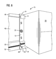
- FIG. 8 illustrates a perspective view of a mounting assembly including an adaptive mounting rail, a support mounting rail and an electronic device in accordance with an exemplary embodiment of the present invention.
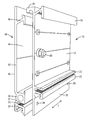
- FIG. 1 illustrates a perspective view of an adaptive mounting rail 10 for electronic devices in accordance with an exemplary embodiment of the present invention.
- a PLC is typically mounted to a back support system, which can include for example a control cabinet wall, shelf etc., via a mounting rail.
- a back support system which can include for example a control cabinet wall, shelf etc., via a mounting rail.
- electronic devices including for example different dimensions, wherein the different types of electronic devices require different form factors for mounting.
- the adaptive mounting rail 10 as illustrated in FIG. 1 comprises a base element 12 with a first side 14 and a second side 16 .
- the first side 14 and second side 16 are opposite each other, wherein the first side 14 can be considered as front and the second side 16 as back of the base element 12 .
- the base element 12 is a generally planar elongated element comprising a length L.
- the length L can comprise any desired dimension.
- the length L of the base element 12 and thereby of the mounting rail 10 can be 160 mm, 482 mm (19 inches), 530 mm, 830 mm, 2000 mm, etc.
- a plurality of rails 18 , 20 , 22 are disposed on the first side 14 of the base element 12 designed for mounting one or more electronic devices to the mounting rail 10 .
- the rails 18 , 20 , 22 extend in a horizontal direction over the entire length L of the base element 12 .
- the plurality of rails 18 , 20 , 22 include the top rail 18 and the bottom rails 20 , 22 .
- the bottom rails 20 , 22 comprise threaded surfaces 21 , 23 .
- the rails 20 , 22 are arranged so that the threaded surfaces 21 , 23 face each other and are arranged relatively close together.
- the threaded surfaces 21 , 23 form a gap or interspace for receiving bolts or screws which are used to fasten an electronic device to the mounting rail 10 .
- the mounting rail 10 comprises a plurality of adaptive elements.
- a first adaptive mounting element 24 is disposed on the second side 16 of the base element 12 and can be configured for example as a top mounting hanger.
- a second adaptive mounting element 26 is part of or incorporated into the base element 12 and can be for example an extended bottom portion of the base element 12 .
- the second adaptive mounting element 26 comprises one or more openings 28 , for example bore holes, for securely fastening the mounting rail 10 to a further mounting rail, herein referred to as support mounting rail.
- the adaptive elements 24 , 26 allow to removably mount the mounting rail 10 to the support mounting rail which will be explained in detail with reference to FIGS. 4-8 .
- FIG. 1 illustrates that the mounting rail 10 is an integrated, one piece component.
- the mounting rail 10 comprises metal, in particular aluminum.
- the mounting rail 10 can be an extruded aluminum component.
- the mounting rail 10 can be used as a grounding surface because of the electrical conductivity of metal.
- metal is typically a good heat conductor and therefore the mounting rail 10 can be used as a heat sink to help dissipate heat from the device(s) mounted to the rail 10 .
- the mounting rail 10 can comprise other suitable metals comprising the described characteristics.
- the adaptive mounting rail 10 is designed for mounting one or more PLC(s), such as for example a PLC SIMATIC® S7-300 provided by the Applicant.
- PLC PLC SIMATIC® S7-300
- Such a PLC can be fastened to the mounting rail 10 directly with one or more screws using the threaded surfaces 21 , 23 of the bottom rails 20 , 22 .
- other electronic devices suitable for the mounting rail 10 may be mounted to the adaptive mounting rail 10 .
- FIG. 2 illustrates a side view
- FIG. 3 illustrates a front view of the adaptive mounting rail 10 in accordance with an exemplary embodiment of the present invention.
- FIGS. 2 and 3 further illustrate a mounting element 30 , which can comprise for example a screw or bolt.
- the mounting element 30 is configured as a ground conductor bolt for grounding any mounted device(s) to the mounting rail 10 .
- the mounting rail 10 comprises metal thereby providing a grounding surface for any mounted device(s).
- the mounting element 30 helps reduce the likelihood of a mounted device being damaged from electrical discharge.
- the base element 12 comprises a corresponding opening for inserting the mounting element 30 .
- the base element 12 can comprise a plurality of openings 32 .
- the openings 32 are configured as mounting holes which can be used for installing the mounting rail 10 for example to a control cabinet or other back support system when the adaptive mounting rail 10 is not mounted to a further mounting rail.
- the mounting rail 10 is an integrated, one piece component
- the mounting rail 10 can alternatively be designed as multi-element component.
- the adaptive mounting elements 24 , 26 can be attached to the base element 12 , for example by welding or brazing or alternatively via bolted connections.
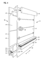
- FIG. 4 illustrates a perspective view of the adaptive mounting rail 10 and an exemplary support mounting rail 40 for electronic devices in accordance with an exemplary embodiment of the present invention.
- the support mounting rail 40 is configured as a mounting rail for different electronic devices compared to those mountable to the adaptive mounting rail 10 .
- the adaptive mounting rail 10 can be designed for mounting one or more PLC(s), for example a PLC SIMATIC® S7-300 provided by the Applicant, wherein the support mounting rail 40 can be designed for mounting one or more PLC(s), for example a PLC SIMATIC® S7-1500 provided by the Applicant.
- PLC PLC SIMATIC® S7-300 provided by the Applicant
- PLC SIMATIC® S7-1500 provided by the Applicant.
- Such a PLC can be fastened to the mounting rail 40 with a single screw, wherein the support mounting rail 40 is installed by screwing to a back support system such as for example a control cabinet wall.
- the support mounting rail 40 comprises a base element 42 with a first side 44 and a second side 46 .
- the first side 44 and second side 46 are opposite each other, wherein the first side 44 can be considered as front and the second side 46 as back of the base element 42 .
- the base element 42 is a generally planar elongated element comprising a length L.
- the length L can comprise any desired dimension.
- the length L of the base element 42 and thereby of the mounting rail 40 can be 160 mm, 482 mm (19 inches), 530 mm, 830 mm, 2000 mm, etc.
- the support mounting rail 40 and the adaptive mounting rail 10 can comprise a same length L or can comprise different lengths L. In an embodiment, the length L of the adaptive mounting rail 10 is equal or less than a length of the support mounting rail 40 .
- a plurality of rails 48 , 50 , 52 are disposed on the first side 44 of the base element 42 for mounting one or more electronic devices to the mounting rail 40 .
- the rails 48 , 50 , 52 extend in a horizontal direction over the entire length L of the base element 42 and the mounting rail 40 .
- the plurality of rails 48 , 50 , 52 include the top rail 48 and the bottom rails 50 , 52 .
- the bottom rails 50 , 52 comprise threaded surfaces 51 , 53 .
- the rails 50 , 52 are arranged so that the threaded surfaces 51 , 53 face each other and are arranged relatively close together.
- the threaded surfaces 51 , 53 form a gap or interspace for receiving bolts or screws which are used to fasten an electronic device to the mounting rail 40 .
- the bottom rails 50 , 52 form an integrated DIN rail for snapping on a wide range of standard electronic components such as for example terminals, miniature circuit breakers, or small relays.
- the support mounting rail 40 is an integrated, one piece component.
- the mounting rail 40 comprises metal, in particular aluminum.
- the support mounting rail 40 can be an extruded aluminum component.
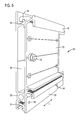
- FIG. 5 illustrates a perspective view of a mounting assembly 60 including the adaptive mounting rail 10 and the support mounting rail 40 in accordance with an exemplary embodiment of the present invention.
- FIG. 5 illustrates the adaptive mounting rail 10 assembled with the support mounting rail 40 .
- the concept includes hanging and screwing the adaptive mounting rail 10 to the further mounting rail 40 in a similar manner to how an electronic device for the support mounting rail 40 would be mounted to the mounting rail 40 .
- the adaptive mounting rail 10 is designed to rest flush against the support mounting rail 40 .
- the first adaptive element 24 of the adaptive mounting rail 10 is designed to rest on the top rail 48 of the support mounting rail 40 .
- the second adaptive element 26 of the mounting rail 10 rests flush against the bottom rails 50 , 52 of the mounting rail 40 .
- the openings 28 of the second adaptive element 26 are placed so that bolts or screws 29 inserted in the openings 28 are received by the opposed threaded surfaces 51 , 53 of the bottom rails 50 , 52 to securely fasten the adaptive mounting rail 10 to the support mounting rail 40 (see FIG. 8 ).
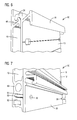
- FIG. 6 illustrates a first enlarged perspective view of a first part of a mounting assembly 60 as illustrated in FIG. 5 in accordance with an exemplary embodiment of the present invention.
- the first adaptive element 24 of the adaptive mounting rail 10 is configured as a top mounting hanger that allows the mounting rail 10 to rest on the support mounting rail 40 , specifically on the top rail 48 of the mounting rail 40 .
- FIG. 7 illustrates a second enlarged perspective view of a second part of a mounting assembly 60 as illustrated in FIG. 5 in accordance with an exemplary embodiment of the present invention.
- the second adaptive element 26 of the adaptive mounting rail 10 configured as extended bottom portion of the base element 12 , rests flush at least partially against the bottom rails 50 , 52 of the support mounting rail 40 .
- the adaptive mounting rail 10 can be securely fastened to the mounting rail 40 .
- FIG. 8 illustrates a perspective view of a mounting assembly 70 including the adaptive mounting rail 10 , the support mounting rail 40 and an electronic device 80 in accordance with an exemplary embodiment of the present invention.
- the first adaptive element 24 configured as a top mounting hanger of the adaptive mounting rail 10 , is placed on top of the top rail 48 of the support mounting rail 40 at a slight angle.
- the slight angle between the adaptive mounting rail 10 and the support mounting rail 40 can be for example between 1° and 90°.
- the adaptive mounting rail 10 is pivoted down and fastened securely to the support mounting rail 40 via the second adaptive element 26 of the mounting rail 10 .
- the mounting rail 10 is screwed securely to the support mounting rail 40 using screws or bolts 29 through openings 28 to anchor between threaded surfaces 51 and 53 to secure element 26 to the face of bottom rails 50 and 52 .
- the electronic device 80 is mounted to the adaptive mounting rail 10 in a similar manner.
- the top portion of the electronic device 80 is placed on top of the top rail 18 of the adaptive mounting rail 10 at a slight angle, for example between 1° and 90° measured between the mounting rail 10 and the electronic device 80 , pivoted down and fastened, for example screwed, securely to the adaptive mounted rail 10 .
- the electronic device 80 can be a PLC including a power supply module, a central processing unit (CPU), interface modules, input/output modules, etc.
- many other electronic devices suitable for the mounting rail 10 may be mounted to the mounting rail 10 .
- Electronic devices may also be mounted to the support mounting rail 40 , for example when the adaptive mounting rail 10 is shorter in length than the support mounting rail 40 as illustrated for example in FIG. 8 .
- the adaptive mounting rail 10 is configured so that one or more electronic devices are mountable to the mounting rail 10 while in turn the mounting rail 10 is mountable to the support mounting rail 40 which comprises different form factors for mounting different electronic devices.
- a customer or user has installed the support mounting rail 40 within a control cabinet for electronic devices. If the customer or user wishes to install an electronic device which requires the form factors of the mounting rail 10 , the customer or user simply mounts the adaptive mounting rail 10 to the existing mounting rail 40 and can then install the electronic devices for the mounting rail 10 . Without the adaptive mounting rail 10 , the customer would have to remove the mounting rail 40 and install a new mounting rail conforming to the specific form factors of the electronic devices. Furthermore, since the adaptive mounting rail 10 is removably mounted to the support mounting rail 40 , the mounting rail 10 can be easily removed (and installed again) at any time and the entire support mounting rail 40 can be used for mounting electronic devices.
Landscapes
- Engineering & Computer Science (AREA)
- Microelectronics & Electronic Packaging (AREA)
- Automation & Control Theory (AREA)
- Physics & Mathematics (AREA)
- General Physics & Mathematics (AREA)
- Mounting Components In General For Electric Apparatus (AREA)
Abstract
Description
- Aspects of the present invention generally relate to an adaptive mounting rail and mounting assemblies for electronic devices, such as for example control devices including but not limited to programmable logic controllers.
- Industrial control systems can be used for monitoring parameters and/or controlling devices. Within industrial control systems, one or more sensors may be communicatively coupled to one or more electronic devices, such as for example programmable logic controller(s), herein referred to as PLC or PLCs, via one or more input/output (I/O) modules (e.g., a communication module). Via the I/O modules, the PLC(s) may control one or more devices such as, for example, a rheostat, a switch, a sequencer, a servo drive, a motor, and/or a valve etc.
- A PLC is typically mounted to a back support system, which can include for example a control cabinet wall, shelf etc., via a mounting rail. There are different types of PLCs including for example different dimensions, wherein the different types of PLCs can require different form factors for mounting. For example, a PLC provided by the Applicant under the name SIMATIC® S7-300 conforms to a specific S7-300 mounting rail, wherein a PLC provided by the Applicant under the name SIMATIC® S7-1500 conforms to a specific S7-1500 mounting rail. A device that conforms to a S7-300 mounting rail cannot be mounted on a S7-1500 mounting rail. This can pose a problem for a customer because crucial real estate within a control enclosure is not being utilized to its maximum potential. Furthermore, each time an existing PLC needs to be replaced with another PLC of a different type, the mounting rail also needs to be changed which causes extra costs and time to install. Thus, a need exists for an improved mounting rail and mounting assemblies for mounting different electronic devices.
- Briefly described, aspects of the present invention relate to an adaptive mounting rail and mounting assemblies for electronic devices, such as for example control devices including but not limited to PLCs.
- A first aspect of the present invention provides an adaptive mounting rail for an electronic device comprising a base element comprising a first side and a second side, a plurality of rails disposed on the first side of the base element for mounting an electronic device, and a first adaptive mounting element disposed on the second side of the base element allowing to removably mount the mounting rail to a support mounting rail.
- A second aspect of the present invention provides a mounting assembly for electronic devices comprising an adaptive mounting rail comprising a base element comprising a first side and a second side, a plurality of rails disposed on the first side of the base element, and a first adaptive mounting element disposed on the second side of the base element, and a support mounting rail, wherein the adaptive mounting rail is removably mounted to the support mounting rail by the first adaptive mounting element, and wherein one or more electronic devices are mountable to the adaptive mounting rail via the plurality of rails.
- A third aspect of the present invention provides a mounting assembly for electronic devices comprising an adaptive mounting rail comprising a base element comprising a first side and a second side, a plurality of rails disposed on the first side of the base element, and a first adaptive mounting element disposed on the second side of the base element, a support mounting rail, wherein the adaptive mounting rail is removably mounted to the support mounting rail via the first adaptive mounting element, and an electronic device removably mounted to the support mounting rail via the adaptive mounting rail.
-
FIG. 1 illustrates a perspective view of an adaptive mounting rail for electronic devices in accordance with an exemplary embodiment of the present invention. -
FIG. 2 illustrates a side view of an adaptive mounting rail for electronic devices in accordance with an exemplary embodiment of the present invention. -
FIG. 3 illustrates a front view of an adaptive mounting rail for electronic devices in accordance with an exemplary embodiment of the present invention. -
FIG. 4 illustrates a perspective view of an adaptive mounting rail and a support mounting rail for electronic devices in accordance with an exemplary embodiment of the present invention. -
FIG. 5 illustrates a perspective view of a mounting assembly including an adaptive mounting rail in accordance with an exemplary embodiment of the present invention. -
FIG. 6 illustrates a first enlarged perspective view of a first part of a mounting assembly as illustrated inFIG. 5 in accordance with an exemplary embodiment of the present invention. -
FIG. 7 illustrates a second enlarged perspective view of a second part of a mounting assembly as illustrated inFIG. 5 in accordance with an exemplary embodiment of the present invention. -
FIG. 8 illustrates a perspective view of a mounting assembly including an adaptive mounting rail, a support mounting rail and an electronic device in accordance with an exemplary embodiment of the present invention. - To facilitate an understanding of embodiments, principles, and features of the present invention, they are explained hereinafter with reference to implementation in illustrative embodiments. In particular, they are described in the context of an adaptive mounting rail and mounting assemblies including such an adaptive mounting rail for electronic devices, in particular for control devices such as a PLC. Embodiments of the present invention, however, are not limited to use in the described devices or methods.
- The components and materials described hereinafter as making up the various embodiments are intended to be illustrative and not restrictive. Many suitable components and materials that would perform the same or a similar function as the materials described herein are intended to be embraced within the scope of embodiments of the present invention.
-
FIG. 1 illustrates a perspective view of anadaptive mounting rail 10 for electronic devices in accordance with an exemplary embodiment of the present invention. - As noted before, a PLC is typically mounted to a back support system, which can include for example a control cabinet wall, shelf etc., via a mounting rail. There are different types of electronic devices including for example different dimensions, wherein the different types of electronic devices require different form factors for mounting.
- The
adaptive mounting rail 10 as illustrated inFIG. 1 comprises abase element 12 with afirst side 14 and asecond side 16. Thefirst side 14 andsecond side 16 are opposite each other, wherein thefirst side 14 can be considered as front and thesecond side 16 as back of thebase element 12. Thebase element 12 is a generally planar elongated element comprising a length L. The length L can comprise any desired dimension. For example, the length L of thebase element 12 and thereby of themounting rail 10 can be 160 mm, 482 mm (19 inches), 530 mm, 830 mm, 2000 mm, etc. - A plurality of
rails first side 14 of thebase element 12 designed for mounting one or more electronic devices to themounting rail 10. Therails base element 12. The plurality ofrails top rail 18 and thebottom rails bottom rails surfaces rails surfaces surfaces mounting rail 10. - Furthermore, the
mounting rail 10 comprises a plurality of adaptive elements. A firstadaptive mounting element 24 is disposed on thesecond side 16 of thebase element 12 and can be configured for example as a top mounting hanger. A secondadaptive mounting element 26 is part of or incorporated into thebase element 12 and can be for example an extended bottom portion of thebase element 12. According to an exemplary embodiment, the secondadaptive mounting element 26 comprises one ormore openings 28, for example bore holes, for securely fastening themounting rail 10 to a further mounting rail, herein referred to as support mounting rail. Theadaptive elements mounting rail 10 to the support mounting rail which will be explained in detail with reference toFIGS. 4-8 . -
FIG. 1 illustrates that themounting rail 10 is an integrated, one piece component. According to an exemplary embodiment, themounting rail 10 comprises metal, in particular aluminum. For example, themounting rail 10 can be an extruded aluminum component. By using metal for themounting rail 10, themounting rail 10 can be used as a grounding surface because of the electrical conductivity of metal. In addition, metal is typically a good heat conductor and therefore themounting rail 10 can be used as a heat sink to help dissipate heat from the device(s) mounted to therail 10. It should be noted that themounting rail 10 can comprise other suitable metals comprising the described characteristics. - In an exemplary embodiment, the
adaptive mounting rail 10 is designed for mounting one or more PLC(s), such as for example a PLC SIMATIC® S7-300 provided by the Applicant. Such a PLC can be fastened to themounting rail 10 directly with one or more screws using the threadedsurfaces bottom rails mounting rail 10 may be mounted to theadaptive mounting rail 10. -
FIG. 2 illustrates a side view andFIG. 3 illustrates a front view of theadaptive mounting rail 10 in accordance with an exemplary embodiment of the present invention. -
FIGS. 2 and 3 further illustrate amounting element 30, which can comprise for example a screw or bolt. Themounting element 30 is configured as a ground conductor bolt for grounding any mounted device(s) to themounting rail 10. As previously noted, the mountingrail 10 comprises metal thereby providing a grounding surface for any mounted device(s). The mountingelement 30 helps reduce the likelihood of a mounted device being damaged from electrical discharge. Of course, thebase element 12 comprises a corresponding opening for inserting the mountingelement 30. - With reference to
FIG. 3 , thebase element 12 can comprise a plurality ofopenings 32. Theopenings 32 are configured as mounting holes which can be used for installing the mountingrail 10 for example to a control cabinet or other back support system when the adaptive mountingrail 10 is not mounted to a further mounting rail. - Although it is preferred that the mounting
rail 10 is an integrated, one piece component, the mountingrail 10 can alternatively be designed as multi-element component. AsFIG. 2 illustrates, the adaptive mountingelements base element 12, for example by welding or brazing or alternatively via bolted connections. -
FIG. 4 illustrates a perspective view of the adaptive mountingrail 10 and an exemplarysupport mounting rail 40 for electronic devices in accordance with an exemplary embodiment of the present invention. - The
support mounting rail 40 is configured as a mounting rail for different electronic devices compared to those mountable to the adaptive mountingrail 10. As noted before, in an exemplary embodiment, the adaptive mountingrail 10 can be designed for mounting one or more PLC(s), for example a PLC SIMATIC® S7-300 provided by the Applicant, wherein thesupport mounting rail 40 can be designed for mounting one or more PLC(s), for example a PLC SIMATIC® S7-1500 provided by the Applicant. Such a PLC can be fastened to the mountingrail 40 with a single screw, wherein thesupport mounting rail 40 is installed by screwing to a back support system such as for example a control cabinet wall. - The
support mounting rail 40 comprises abase element 42 with afirst side 44 and asecond side 46. Thefirst side 44 andsecond side 46 are opposite each other, wherein thefirst side 44 can be considered as front and thesecond side 46 as back of thebase element 42. Thebase element 42 is a generally planar elongated element comprising a length L. The length L can comprise any desired dimension. For example, the length L of thebase element 42 and thereby of the mountingrail 40 can be 160 mm, 482 mm (19 inches), 530 mm, 830 mm, 2000 mm, etc. Thesupport mounting rail 40 and the adaptive mountingrail 10 can comprise a same length L or can comprise different lengths L. In an embodiment, the length L of the adaptive mountingrail 10 is equal or less than a length of thesupport mounting rail 40. - A plurality of
rails first side 44 of thebase element 42 for mounting one or more electronic devices to the mountingrail 40. Therails base element 42 and the mountingrail 40. The plurality ofrails top rail 48 and the bottom rails 50, 52. The bottom rails 50, 52 comprise threadedsurfaces rails rail 40. Further, the bottom rails 50, 52 form an integrated DIN rail for snapping on a wide range of standard electronic components such as for example terminals, miniature circuit breakers, or small relays. - The
support mounting rail 40 is an integrated, one piece component. According to an exemplary embodiment, the mountingrail 40 comprises metal, in particular aluminum. For example, thesupport mounting rail 40 can be an extruded aluminum component. -
FIG. 5 illustrates a perspective view of a mountingassembly 60 including the adaptive mountingrail 10 and thesupport mounting rail 40 in accordance with an exemplary embodiment of the present invention.FIG. 5 illustrates the adaptive mountingrail 10 assembled with thesupport mounting rail 40. The concept includes hanging and screwing the adaptive mountingrail 10 to the further mountingrail 40 in a similar manner to how an electronic device for thesupport mounting rail 40 would be mounted to the mountingrail 40. The adaptive mountingrail 10 is designed to rest flush against thesupport mounting rail 40. - The first
adaptive element 24 of the adaptive mountingrail 10 is designed to rest on thetop rail 48 of thesupport mounting rail 40. The secondadaptive element 26 of the mountingrail 10 rests flush against the bottom rails 50, 52 of the mountingrail 40. Theopenings 28 of the secondadaptive element 26 are placed so that bolts or screws 29 inserted in theopenings 28 are received by the opposed threadedsurfaces rail 10 to the support mounting rail 40 (seeFIG. 8 ). -
FIG. 6 illustrates a first enlarged perspective view of a first part of a mountingassembly 60 as illustrated inFIG. 5 in accordance with an exemplary embodiment of the present invention. As described before, the firstadaptive element 24 of the adaptive mountingrail 10 is configured as a top mounting hanger that allows the mountingrail 10 to rest on thesupport mounting rail 40, specifically on thetop rail 48 of the mountingrail 40. -
FIG. 7 illustrates a second enlarged perspective view of a second part of a mountingassembly 60 as illustrated inFIG. 5 in accordance with an exemplary embodiment of the present invention. The secondadaptive element 26 of the adaptive mountingrail 10, configured as extended bottom portion of thebase element 12, rests flush at least partially against the bottom rails 50, 52 of thesupport mounting rail 40. As described before, using theopenings 28, the adaptive mountingrail 10 can be securely fastened to the mountingrail 40. -
FIG. 8 illustrates a perspective view of a mountingassembly 70 including the adaptive mountingrail 10, thesupport mounting rail 40 and anelectronic device 80 in accordance with an exemplary embodiment of the present invention. - In order to mount the adaptive mounting
rail 10 to thesupport mounting rail 40, the firstadaptive element 24, configured as a top mounting hanger of the adaptive mountingrail 10, is placed on top of thetop rail 48 of thesupport mounting rail 40 at a slight angle. When placing the adaptive element 24 (top mounting hanger) on top of thetop rail 48, the slight angle between the adaptive mountingrail 10 and thesupport mounting rail 40 can be for example between 1° and 90°. Then, the adaptive mountingrail 10 is pivoted down and fastened securely to thesupport mounting rail 40 via the secondadaptive element 26 of the mountingrail 10. Specifically, the mountingrail 10 is screwed securely to thesupport mounting rail 40 using screws orbolts 29 throughopenings 28 to anchor between threadedsurfaces element 26 to the face ofbottom rails - The
electronic device 80 is mounted to the adaptive mountingrail 10 in a similar manner. The top portion of theelectronic device 80 is placed on top of thetop rail 18 of the adaptive mountingrail 10 at a slight angle, for example between 1° and 90° measured between the mountingrail 10 and theelectronic device 80, pivoted down and fastened, for example screwed, securely to the adaptive mountedrail 10. As noted before, theelectronic device 80 can be a PLC including a power supply module, a central processing unit (CPU), interface modules, input/output modules, etc. Of course, many other electronic devices suitable for the mountingrail 10 may be mounted to the mountingrail 10. Electronic devices may also be mounted to thesupport mounting rail 40, for example when the adaptive mountingrail 10 is shorter in length than thesupport mounting rail 40 as illustrated for example inFIG. 8 . - The adaptive mounting
rail 10 is configured so that one or more electronic devices are mountable to the mountingrail 10 while in turn the mountingrail 10 is mountable to thesupport mounting rail 40 which comprises different form factors for mounting different electronic devices. For example, a customer or user has installed thesupport mounting rail 40 within a control cabinet for electronic devices. If the customer or user wishes to install an electronic device which requires the form factors of the mountingrail 10, the customer or user simply mounts the adaptive mountingrail 10 to the existing mountingrail 40 and can then install the electronic devices for the mountingrail 10. Without the adaptive mountingrail 10, the customer would have to remove the mountingrail 40 and install a new mounting rail conforming to the specific form factors of the electronic devices. Furthermore, since the adaptive mountingrail 10 is removably mounted to thesupport mounting rail 40, the mountingrail 10 can be easily removed (and installed again) at any time and the entiresupport mounting rail 40 can be used for mounting electronic devices. - While embodiments of the present invention have been disclosed in exemplary forms, it will be apparent to those skilled in the art that many modifications, additions, and deletions can be made therein without departing from the spirit and scope of the invention and its equivalents, as set forth in the following claims.
Claims (20)
Priority Applications (1)
| Application Number | Priority Date | Filing Date | Title |
|---|---|---|---|
| US15/281,195 US10143104B2 (en) | 2016-09-30 | 2016-09-30 | Adaptive mounting rail and mounting assemblies for electronic devices |
Applications Claiming Priority (1)
| Application Number | Priority Date | Filing Date | Title |
|---|---|---|---|
| US15/281,195 US10143104B2 (en) | 2016-09-30 | 2016-09-30 | Adaptive mounting rail and mounting assemblies for electronic devices |
Publications (2)
| Publication Number | Publication Date |
|---|---|
| US20180098452A1 true US20180098452A1 (en) | 2018-04-05 |
| US10143104B2 US10143104B2 (en) | 2018-11-27 |
Family
ID=61759222
Family Applications (1)
| Application Number | Title | Priority Date | Filing Date |
|---|---|---|---|
| US15/281,195 Active US10143104B2 (en) | 2016-09-30 | 2016-09-30 | Adaptive mounting rail and mounting assemblies for electronic devices |
Country Status (1)
| Country | Link |
|---|---|
| US (1) | US10143104B2 (en) |
Cited By (5)
| Publication number | Priority date | Publication date | Assignee | Title |
|---|---|---|---|---|
| US10533703B1 (en) * | 2018-09-07 | 2020-01-14 | Hewlett Packard Enterprise Development Lp | Mounting system for tool-less attachment of electronic device to a rail |
| US11044991B1 (en) | 2019-03-27 | 2021-06-29 | David Bryner | Portable collapsible support for electronic equipment |
| US11708173B2 (en) * | 2019-08-08 | 2023-07-25 | Textron Innovations Inc. | Avionic sliding rack |
| US11761576B1 (en) * | 2019-03-27 | 2023-09-19 | David Bryner | Portable collapsible support for electronic equipment |
| US12121162B1 (en) * | 2022-07-19 | 2024-10-22 | Dustin Bledsoe | Collectable shelf system |
Families Citing this family (1)
| Publication number | Priority date | Publication date | Assignee | Title |
|---|---|---|---|---|
| US11112058B2 (en) * | 2017-08-11 | 2021-09-07 | Wayne Floe | Quick attach bracket system |
Citations (18)
| Publication number | Priority date | Publication date | Assignee | Title |
|---|---|---|---|---|
| US4764049A (en) * | 1986-02-18 | 1988-08-16 | Pace Incorporated | Universal equipment mounting structure |
| US5584406A (en) * | 1993-09-28 | 1996-12-17 | Rittal-Werk Rudolf Loh Gmbh & Co. Kg | Rack frame |
| US6331935B1 (en) * | 1998-09-29 | 2001-12-18 | Rockwell Automation Technologies, Inc. | Controller assembly having a base unit with a dockable processor unit |
| US20040165357A1 (en) * | 2002-11-27 | 2004-08-26 | Siemens Aktiengesellschaft | Mounting device and apparatus for mounting device |
| US20050175402A1 (en) * | 2004-02-10 | 2005-08-11 | Schurr Larry E. | Apparatus and methods for detachably mounting devices to rails |
| US8344239B2 (en) * | 2004-02-13 | 2013-01-01 | Pvt Solar, Inc. | Mechanism for mounting solar modules |
| US20140132139A1 (en) * | 2012-11-14 | 2014-05-15 | Nan Juen International Co., Ltd. | Track-bearing cabinet fastener |
| US20140179133A1 (en) * | 2012-12-20 | 2014-06-26 | Mounting Systems Gmbh | Fastening system for mounting solar modules |
| US20140340838A1 (en) * | 2013-05-20 | 2014-11-20 | Inventec Corporation | Server and fixing assembly thereof |
| US20150129517A1 (en) * | 2013-11-14 | 2015-05-14 | Ecolibrium Solar, Inc. | Modular Sloped Roof Solar Mounting System |
| US20160262274A1 (en) * | 2015-03-06 | 2016-09-08 | Rockwell Automation Technologies, Inc. | Single action din rail latch |
| US20170055363A1 (en) * | 2014-04-30 | 2017-02-23 | Telefonaktiebolaget Lm Ericsson (Publ) | Mounting of a telecommunication equipment to a structure |
| US20170112016A1 (en) * | 2015-10-16 | 2017-04-20 | King Slide Works Co., Ltd. | Slide rail assembly for rack system |
| US9743541B1 (en) * | 2016-06-22 | 2017-08-22 | Jet Optoelectronics Co., Ltd. | Electronic device for fast assembling and connecting |
| US9747823B2 (en) * | 2014-10-02 | 2017-08-29 | Ann Louise Lorenzini | Portable display board for multimedia devices |
| US20170340111A1 (en) * | 2016-05-31 | 2017-11-30 | King Slide Works Co., Ltd. | Slide rail and slide rail assembly |
| US20170340110A1 (en) * | 2016-05-31 | 2017-11-30 | King Slide Works Co., Ltd. | Slide rail assembly |
| US20180140093A1 (en) * | 2016-11-22 | 2018-05-24 | King Slide Works Co., Ltd. | Supporting device for rail member |
Family Cites Families (1)
| Publication number | Priority date | Publication date | Assignee | Title |
|---|---|---|---|---|
| JP6241263B2 (en) * | 2013-12-20 | 2017-12-06 | 富士通株式会社 | Electronic device, rail structure and rack |
-
2016
- 2016-09-30 US US15/281,195 patent/US10143104B2/en active Active
Patent Citations (18)
| Publication number | Priority date | Publication date | Assignee | Title |
|---|---|---|---|---|
| US4764049A (en) * | 1986-02-18 | 1988-08-16 | Pace Incorporated | Universal equipment mounting structure |
| US5584406A (en) * | 1993-09-28 | 1996-12-17 | Rittal-Werk Rudolf Loh Gmbh & Co. Kg | Rack frame |
| US6331935B1 (en) * | 1998-09-29 | 2001-12-18 | Rockwell Automation Technologies, Inc. | Controller assembly having a base unit with a dockable processor unit |
| US20040165357A1 (en) * | 2002-11-27 | 2004-08-26 | Siemens Aktiengesellschaft | Mounting device and apparatus for mounting device |
| US20050175402A1 (en) * | 2004-02-10 | 2005-08-11 | Schurr Larry E. | Apparatus and methods for detachably mounting devices to rails |
| US8344239B2 (en) * | 2004-02-13 | 2013-01-01 | Pvt Solar, Inc. | Mechanism for mounting solar modules |
| US20140132139A1 (en) * | 2012-11-14 | 2014-05-15 | Nan Juen International Co., Ltd. | Track-bearing cabinet fastener |
| US20140179133A1 (en) * | 2012-12-20 | 2014-06-26 | Mounting Systems Gmbh | Fastening system for mounting solar modules |
| US20140340838A1 (en) * | 2013-05-20 | 2014-11-20 | Inventec Corporation | Server and fixing assembly thereof |
| US20150129517A1 (en) * | 2013-11-14 | 2015-05-14 | Ecolibrium Solar, Inc. | Modular Sloped Roof Solar Mounting System |
| US20170055363A1 (en) * | 2014-04-30 | 2017-02-23 | Telefonaktiebolaget Lm Ericsson (Publ) | Mounting of a telecommunication equipment to a structure |
| US9747823B2 (en) * | 2014-10-02 | 2017-08-29 | Ann Louise Lorenzini | Portable display board for multimedia devices |
| US20160262274A1 (en) * | 2015-03-06 | 2016-09-08 | Rockwell Automation Technologies, Inc. | Single action din rail latch |
| US20170112016A1 (en) * | 2015-10-16 | 2017-04-20 | King Slide Works Co., Ltd. | Slide rail assembly for rack system |
| US20170340111A1 (en) * | 2016-05-31 | 2017-11-30 | King Slide Works Co., Ltd. | Slide rail and slide rail assembly |
| US20170340110A1 (en) * | 2016-05-31 | 2017-11-30 | King Slide Works Co., Ltd. | Slide rail assembly |
| US9743541B1 (en) * | 2016-06-22 | 2017-08-22 | Jet Optoelectronics Co., Ltd. | Electronic device for fast assembling and connecting |
| US20180140093A1 (en) * | 2016-11-22 | 2018-05-24 | King Slide Works Co., Ltd. | Supporting device for rail member |
Cited By (6)
| Publication number | Priority date | Publication date | Assignee | Title |
|---|---|---|---|---|
| US10533703B1 (en) * | 2018-09-07 | 2020-01-14 | Hewlett Packard Enterprise Development Lp | Mounting system for tool-less attachment of electronic device to a rail |
| US11044991B1 (en) | 2019-03-27 | 2021-06-29 | David Bryner | Portable collapsible support for electronic equipment |
| US11761576B1 (en) * | 2019-03-27 | 2023-09-19 | David Bryner | Portable collapsible support for electronic equipment |
| US11708173B2 (en) * | 2019-08-08 | 2023-07-25 | Textron Innovations Inc. | Avionic sliding rack |
| US12121162B1 (en) * | 2022-07-19 | 2024-10-22 | Dustin Bledsoe | Collectable shelf system |
| US12121161B1 (en) * | 2022-07-19 | 2024-10-22 | Dustin Bledsoe | Collectable shelf system |
Also Published As
| Publication number | Publication date |
|---|---|
| US10143104B2 (en) | 2018-11-27 |
Similar Documents
| Publication | Publication Date | Title |
|---|---|---|
| US10143104B2 (en) | Adaptive mounting rail and mounting assemblies for electronic devices | |
| EP2950613B1 (en) | Induction coil assembly and induction hob comprising an induction coil assembly | |
| US6731507B2 (en) | Modular AC input section for a power supply unit | |
| US9698577B2 (en) | Portable power supply unit with bus bar adapter and tool-less connection | |
| US20110043986A1 (en) | Power supply assembly for server rack and method for mounting power supply for server rack | |
| EP3264436A1 (en) | Contactor in power distribution assembly | |
| CA2747015C (en) | Device for holding at least one switch in an enclosure, e.g. a switch cabinet | |
| US20090251033A1 (en) | Mounting bracket and method | |
| US10285301B1 (en) | Multi-axis alignment enclosure system for wall-mounted power delivery system | |
| US20160233597A1 (en) | Electrical device | |
| US8511627B2 (en) | Apparatus for arranging and fastening electrical units in particular in a switchgear cabinet, and a fitting system with such an apparatus | |
| US20150171572A1 (en) | Single-fastener mounting plate for electrical outlets | |
| US20160105992A1 (en) | Apparatus for cooling and mounting a circuit board | |
| US8801442B2 (en) | Device for positioning at least one multiple round plug | |
| EP3045025A1 (en) | A building management rack system | |
| JP4958816B2 (en) | Toolless blank panel | |
| US10921867B2 (en) | Field device of modular construction | |
| KR200473284Y1 (en) | Clamping device for distribution board | |
| CN107355913B (en) | Circuit board mounting structure and air conditioner | |
| CN104303607B (en) | The attachment structure of printed base plate, electronic installation and servo motor | |
| JP7281808B2 (en) | control panel equipment | |
| US20130242494A1 (en) | Drive Unit With Interface | |
| JP6756183B2 (en) | Lighting fixtures for hanging, connectors and lighting systems | |
| EP3793046A1 (en) | Bus line connecting device of control center | |
| CN107643723B (en) | Network distribution adapter for motor control center |
Legal Events
| Date | Code | Title | Description |
|---|---|---|---|
| AS | Assignment |
Owner name: SIEMENS INDUSTRY, INC., GEORGIA Free format text: ASSIGNMENT OF ASSIGNORS INTEREST;ASSIGNORS:BAKER, JAMES H.;MCNABB, SHAWN;REEL/FRAME:040025/0993 Effective date: 20160923 |
|
| STCF | Information on status: patent grant |
Free format text: PATENTED CASE |
|
| MAFP | Maintenance fee payment |
Free format text: PAYMENT OF MAINTENANCE FEE, 4TH YEAR, LARGE ENTITY (ORIGINAL EVENT CODE: M1551); ENTITY STATUS OF PATENT OWNER: LARGE ENTITY Year of fee payment: 4 |
|
| MAFP | Maintenance fee payment |
Free format text: PAYMENT OF MAINTENANCE FEE, 8TH YEAR, LARGE ENTITY (ORIGINAL EVENT CODE: M1552); ENTITY STATUS OF PATENT OWNER: LARGE ENTITY Year of fee payment: 8 |