US20180017841A1 - Second harmonic generation - Google Patents
Second harmonic generation Download PDFInfo
- Publication number
- US20180017841A1 US20180017841A1 US15/716,159 US201715716159A US2018017841A1 US 20180017841 A1 US20180017841 A1 US 20180017841A1 US 201715716159 A US201715716159 A US 201715716159A US 2018017841 A1 US2018017841 A1 US 2018017841A1
- Authority
- US
- United States
- Prior art keywords
- optical beam
- harmonic
- fundamental optical
- crystal
- polarization
- Prior art date
- Legal status (The legal status is an assumption and is not a legal conclusion. Google has not performed a legal analysis and makes no representation as to the accuracy of the status listed.)
- Granted
Links
- 230000003287 optical effect Effects 0.000 claims abstract description 358
- 239000013078 crystal Substances 0.000 claims abstract description 138
- 230000010287 polarization Effects 0.000 claims description 102
- 238000000034 method Methods 0.000 claims description 33
- 230000001902 propagating effect Effects 0.000 claims description 6
- 238000000926 separation method Methods 0.000 claims description 4
- 239000011248 coating agent Substances 0.000 claims description 3
- 238000000576 coating method Methods 0.000 claims description 3
- 238000006243 chemical reaction Methods 0.000 description 44
- 230000008569 process Effects 0.000 description 13
- 238000010586 diagram Methods 0.000 description 7
- 230000008901 benefit Effects 0.000 description 5
- 239000000463 material Substances 0.000 description 5
- 238000010009 beating Methods 0.000 description 4
- 230000006870 function Effects 0.000 description 3
- GQYHUHYESMUTHG-UHFFFAOYSA-N lithium niobate Chemical compound [Li+].[O-][Nb](=O)=O GQYHUHYESMUTHG-UHFFFAOYSA-N 0.000 description 3
- 238000004519 manufacturing process Methods 0.000 description 3
- 230000001154 acute effect Effects 0.000 description 2
- 230000008859 change Effects 0.000 description 2
- 230000001419 dependent effect Effects 0.000 description 2
- 230000000694 effects Effects 0.000 description 2
- 230000000644 propagated effect Effects 0.000 description 2
- 230000035945 sensitivity Effects 0.000 description 2
- 230000001360 synchronised effect Effects 0.000 description 2
- 230000015556 catabolic process Effects 0.000 description 1
- 230000008878 coupling Effects 0.000 description 1
- 238000010168 coupling process Methods 0.000 description 1
- 238000005859 coupling reaction Methods 0.000 description 1
- 230000003247 decreasing effect Effects 0.000 description 1
- 238000006731 degradation reaction Methods 0.000 description 1
- 230000003111 delayed effect Effects 0.000 description 1
- 239000006185 dispersion Substances 0.000 description 1
- 230000003993 interaction Effects 0.000 description 1
- 238000003913 materials processing Methods 0.000 description 1
- 239000000203 mixture Substances 0.000 description 1
- 238000012986 modification Methods 0.000 description 1
- 230000004048 modification Effects 0.000 description 1
- 239000013307 optical fiber Substances 0.000 description 1
- 230000000737 periodic effect Effects 0.000 description 1
- 238000005086 pumping Methods 0.000 description 1
- 238000004611 spectroscopical analysis Methods 0.000 description 1
- 239000010409 thin film Substances 0.000 description 1
Images


Classifications
-
- G—PHYSICS
- G02—OPTICS
- G02F—OPTICAL DEVICES OR ARRANGEMENTS FOR THE CONTROL OF LIGHT BY MODIFICATION OF THE OPTICAL PROPERTIES OF THE MEDIA OF THE ELEMENTS INVOLVED THEREIN; NON-LINEAR OPTICS; FREQUENCY-CHANGING OF LIGHT; OPTICAL LOGIC ELEMENTS; OPTICAL ANALOGUE/DIGITAL CONVERTERS
- G02F1/00—Devices or arrangements for the control of the intensity, colour, phase, polarisation or direction of light arriving from an independent light source, e.g. switching, gating or modulating; Non-linear optics
- G02F1/35—Non-linear optics
- G02F1/37—Non-linear optics for second-harmonic generation
-
- G—PHYSICS
- G02—OPTICS
- G02F—OPTICAL DEVICES OR ARRANGEMENTS FOR THE CONTROL OF LIGHT BY MODIFICATION OF THE OPTICAL PROPERTIES OF THE MEDIA OF THE ELEMENTS INVOLVED THEREIN; NON-LINEAR OPTICS; FREQUENCY-CHANGING OF LIGHT; OPTICAL LOGIC ELEMENTS; OPTICAL ANALOGUE/DIGITAL CONVERTERS
- G02F1/00—Devices or arrangements for the control of the intensity, colour, phase, polarisation or direction of light arriving from an independent light source, e.g. switching, gating or modulating; Non-linear optics
- G02F1/35—Non-linear optics
- G02F1/3501—Constructional details or arrangements of non-linear optical devices, e.g. shape of non-linear crystals
-
- G—PHYSICS
- G02—OPTICS
- G02F—OPTICAL DEVICES OR ARRANGEMENTS FOR THE CONTROL OF LIGHT BY MODIFICATION OF THE OPTICAL PROPERTIES OF THE MEDIA OF THE ELEMENTS INVOLVED THEREIN; NON-LINEAR OPTICS; FREQUENCY-CHANGING OF LIGHT; OPTICAL LOGIC ELEMENTS; OPTICAL ANALOGUE/DIGITAL CONVERTERS
- G02F1/00—Devices or arrangements for the control of the intensity, colour, phase, polarisation or direction of light arriving from an independent light source, e.g. switching, gating or modulating; Non-linear optics
- G02F1/35—Non-linear optics
- G02F1/353—Frequency conversion, i.e. wherein a light beam is generated with frequency components different from those of the incident light beams
-
- G—PHYSICS
- G02—OPTICS
- G02F—OPTICAL DEVICES OR ARRANGEMENTS FOR THE CONTROL OF LIGHT BY MODIFICATION OF THE OPTICAL PROPERTIES OF THE MEDIA OF THE ELEMENTS INVOLVED THEREIN; NON-LINEAR OPTICS; FREQUENCY-CHANGING OF LIGHT; OPTICAL LOGIC ELEMENTS; OPTICAL ANALOGUE/DIGITAL CONVERTERS
- G02F1/00—Devices or arrangements for the control of the intensity, colour, phase, polarisation or direction of light arriving from an independent light source, e.g. switching, gating or modulating; Non-linear optics
- G02F1/35—Non-linear optics
- G02F1/355—Non-linear optics characterised by the materials used
- G02F1/3551—Crystals
-
- H—ELECTRICITY
- H01—ELECTRIC ELEMENTS
- H01S—DEVICES USING THE PROCESS OF LIGHT AMPLIFICATION BY STIMULATED EMISSION OF RADIATION [LASER] TO AMPLIFY OR GENERATE LIGHT; DEVICES USING STIMULATED EMISSION OF ELECTROMAGNETIC RADIATION IN WAVE RANGES OTHER THAN OPTICAL
- H01S3/00—Lasers, i.e. devices using stimulated emission of electromagnetic radiation in the infrared, visible or ultraviolet wave range
- H01S3/005—Optical devices external to the laser cavity, specially adapted for lasers, e.g. for homogenisation of the beam or for manipulating laser pulses, e.g. pulse shaping
- H01S3/0092—Nonlinear frequency conversion, e.g. second harmonic generation [SHG] or sum- or difference-frequency generation outside the laser cavity
-
- G—PHYSICS
- G02—OPTICS
- G02F—OPTICAL DEVICES OR ARRANGEMENTS FOR THE CONTROL OF LIGHT BY MODIFICATION OF THE OPTICAL PROPERTIES OF THE MEDIA OF THE ELEMENTS INVOLVED THEREIN; NON-LINEAR OPTICS; FREQUENCY-CHANGING OF LIGHT; OPTICAL LOGIC ELEMENTS; OPTICAL ANALOGUE/DIGITAL CONVERTERS
- G02F1/00—Devices or arrangements for the control of the intensity, colour, phase, polarisation or direction of light arriving from an independent light source, e.g. switching, gating or modulating; Non-linear optics
- G02F1/35—Non-linear optics
- G02F1/3501—Constructional details or arrangements of non-linear optical devices, e.g. shape of non-linear crystals
- G02F1/3503—Structural association of optical elements, e.g. lenses, with the non-linear optical device
-
- G—PHYSICS
- G02—OPTICS
- G02F—OPTICAL DEVICES OR ARRANGEMENTS FOR THE CONTROL OF LIGHT BY MODIFICATION OF THE OPTICAL PROPERTIES OF THE MEDIA OF THE ELEMENTS INVOLVED THEREIN; NON-LINEAR OPTICS; FREQUENCY-CHANGING OF LIGHT; OPTICAL LOGIC ELEMENTS; OPTICAL ANALOGUE/DIGITAL CONVERTERS
- G02F1/00—Devices or arrangements for the control of the intensity, colour, phase, polarisation or direction of light arriving from an independent light source, e.g. switching, gating or modulating; Non-linear optics
- G02F1/35—Non-linear optics
- G02F1/3501—Constructional details or arrangements of non-linear optical devices, e.g. shape of non-linear crystals
- G02F1/3505—Coatings; Housings; Supports
-
- G—PHYSICS
- G02—OPTICS
- G02F—OPTICAL DEVICES OR ARRANGEMENTS FOR THE CONTROL OF LIGHT BY MODIFICATION OF THE OPTICAL PROPERTIES OF THE MEDIA OF THE ELEMENTS INVOLVED THEREIN; NON-LINEAR OPTICS; FREQUENCY-CHANGING OF LIGHT; OPTICAL LOGIC ELEMENTS; OPTICAL ANALOGUE/DIGITAL CONVERTERS
- G02F1/00—Devices or arrangements for the control of the intensity, colour, phase, polarisation or direction of light arriving from an independent light source, e.g. switching, gating or modulating; Non-linear optics
- G02F1/35—Non-linear optics
- G02F1/3501—Constructional details or arrangements of non-linear optical devices, e.g. shape of non-linear crystals
- G02F1/3507—Arrangements comprising two or more nonlinear optical devices
-
- G—PHYSICS
- G02—OPTICS
- G02F—OPTICAL DEVICES OR ARRANGEMENTS FOR THE CONTROL OF LIGHT BY MODIFICATION OF THE OPTICAL PROPERTIES OF THE MEDIA OF THE ELEMENTS INVOLVED THEREIN; NON-LINEAR OPTICS; FREQUENCY-CHANGING OF LIGHT; OPTICAL LOGIC ELEMENTS; OPTICAL ANALOGUE/DIGITAL CONVERTERS
- G02F1/00—Devices or arrangements for the control of the intensity, colour, phase, polarisation or direction of light arriving from an independent light source, e.g. switching, gating or modulating; Non-linear optics
- G02F1/35—Non-linear optics
- G02F1/3501—Constructional details or arrangements of non-linear optical devices, e.g. shape of non-linear crystals
- G02F1/3509—Shape, e.g. shape of end face
-
- G—PHYSICS
- G02—OPTICS
- G02F—OPTICAL DEVICES OR ARRANGEMENTS FOR THE CONTROL OF LIGHT BY MODIFICATION OF THE OPTICAL PROPERTIES OF THE MEDIA OF THE ELEMENTS INVOLVED THEREIN; NON-LINEAR OPTICS; FREQUENCY-CHANGING OF LIGHT; OPTICAL LOGIC ELEMENTS; OPTICAL ANALOGUE/DIGITAL CONVERTERS
- G02F1/00—Devices or arrangements for the control of the intensity, colour, phase, polarisation or direction of light arriving from an independent light source, e.g. switching, gating or modulating; Non-linear optics
- G02F1/35—Non-linear optics
- G02F1/353—Frequency conversion, i.e. wherein a light beam is generated with frequency components different from those of the incident light beams
- G02F1/354—Third or higher harmonic generation
-
- G02F2001/3503—
-
- G02F2001/3507—
-
- G02F2001/3509—
-
- G02F2001/354—
-
- G—PHYSICS
- G02—OPTICS
- G02F—OPTICAL DEVICES OR ARRANGEMENTS FOR THE CONTROL OF LIGHT BY MODIFICATION OF THE OPTICAL PROPERTIES OF THE MEDIA OF THE ELEMENTS INVOLVED THEREIN; NON-LINEAR OPTICS; FREQUENCY-CHANGING OF LIGHT; OPTICAL LOGIC ELEMENTS; OPTICAL ANALOGUE/DIGITAL CONVERTERS
- G02F2201/00—Constructional arrangements not provided for in groups G02F1/00 - G02F7/00
- G02F2201/20—Constructional arrangements not provided for in groups G02F1/00 - G02F7/00 delay line
-
- G—PHYSICS
- G02—OPTICS
- G02F—OPTICAL DEVICES OR ARRANGEMENTS FOR THE CONTROL OF LIGHT BY MODIFICATION OF THE OPTICAL PROPERTIES OF THE MEDIA OF THE ELEMENTS INVOLVED THEREIN; NON-LINEAR OPTICS; FREQUENCY-CHANGING OF LIGHT; OPTICAL LOGIC ELEMENTS; OPTICAL ANALOGUE/DIGITAL CONVERTERS
- G02F2203/00—Function characteristic
- G02F2203/05—Function characteristic wavelength dependent
- G02F2203/055—Function characteristic wavelength dependent wavelength filtering
Definitions
- the present disclosure relates to second harmonic generation and, more particularly, to devices and methods for second harmonic generation using a looped configuration.
- Optical harmonic generation may be used to convert laser light from one wavelength to a shorter wavelength (i.e., a higher frequency).
- frequency doubling, or second harmonic generation (SHG) may be used to obtain visible light from near infrared light.
- the frequency doubled light may then be used for generating frequency tripled light, spectroscopy, materials processing, optical pumping, and/or the like.
- FIG. 1 is a diagram illustrating a prior art second harmonic generator 10 .
- prior art second harmonic generator 10 includes second harmonic crystal 14 .
- fundamental optical beam 11 at optical frequency ⁇ impinges on second harmonic crystal 14 . Since a nonlinear conversion efficiency of second harmonic crystal 14 is less than 100%, only a portion of fundamental optical beam 11 is frequency doubled within second harmonic crystal 14 , so that second harmonic beam 12 at a second harmonic frequency 2 ⁇ exits second harmonic crystal 14 together with an unconverted portion 11 A of fundamental optical beam 11 at optical frequency ⁇ .
- second harmonic crystal 14 two beams exit second harmonic crystal 14 : unconverted portion 11 A of fundamental optical beam 11 and second harmonic beam 12 .
- second harmonic beam 12 and unconverted portion 11 A may impinge on a third harmonic crystal (not shown), which converts a portion of these beams into a third harmonic beam at a third harmonic frequency.
- second harmonic beam 12 may be propagated for another purpose.
- prior art second harmonic generator 10 may include a dichroic mirror (or filter) that redirects unconverted portion 11 A and transmits second harmonic beam 12 as an output.
- a second harmonic generator may include: a combiner to combine a fundamental optical beam with a residual fundamental optical beam; and a second harmonic crystal, coupled to the combiner, to generate a second harmonic optical beam from the fundamental optical beam and the residual fundamental optical beam, wherein, upon generation of the second harmonic optical beam, the residual fundamental optical beam may exit the second harmonic crystal.
- a method may include: propagating, by a second harmonic generator, a fundamental optical beam through a second harmonic crystal to generate a second harmonic optical beam from the fundamental optical beam and a residual fundamental optical beam, wherein, upon generation of the second harmonic optical beam, the residual fundamental optical beam may exit the second harmonic crystal; and propagating, by the second harmonic generator, the residual fundamental optical beam such that the residual fundamental optical beam enters the second harmonic crystal with the fundamental optical beam so as to generate the second harmonic optical beam.
- a laser may include: a combiner to combine a fundamental optical beam with a residual fundamental optical beam; a second harmonic crystal to generate a second harmonic optical beam from the fundamental optical beam and the residual fundamental optical beam, wherein, upon generation of the second harmonic optical beam, the residual fundamental optical beam may exit the second harmonic crystal; and one or more optical components to direct the residual fundamental optical beam to the combiner.
- FIG. 1 illustrates a schematic block diagram of a prior art second harmonic generator
- FIGS. 2A-2D are diagrams showing an example implementation of a second harmonic generator with a looped configuration for second harmonic generation
- FIG. 3 is a diagram showing another example implementation of a second harmonic generator with a looped configuration for second harmonic generation
- FIG. 4 is an example graphical representation associated with an example of non-collinear phasematching enabled by a looped configuration for second harmonic generation
- FIG. 5 is a flow chart of an example process for second harmonic optical generation using a looped configuration, as described herein.
- a typical prior art second harmonic generation scheme uses Type-I collinear second harmonic generation.
- fundamental photons to be combined are identical photons within a single incoming beam (e.g., fundamental optical beam 11 ).
- each second-harmonic photon is formed from a pair of fundamental photons in linear polarization states that are orthogonal to one another.
- the input optical beam may be, for example, a single circularly-polarized beam or a single linearly-polarized beam oriented at 45° to two linear states to be combined in the second harmonic generator (in either case providing equal numbers of photons in each orthogonal polarization).
- phasematching can be critical or non-critical.
- Non-critical phasematching has well-known advantages regarding walk-off and angular sensitivity.
- non-critical phasematching may be difficult to achieve in a prior art second harmonic generation configuration (e.g., such as that shown in FIG. 1 ) since non-critical phasematching relies on precise coincidences of refractive indices associated with a non-linear crystal material, generally assisted by temperature tuning.
- non-collinear phasematching is not possible (e.g., since both incoming photons are in the same fundamental optical beam).
- Another drawback of the prior art second harmonic generator is that tight focusing of the fundamental optical beam into the second harmonic crystal is typically required in order to obtain a reasonable conversion efficiency. Such tight focusing results in a small spot diameter of the fundamental optical beam that may compromise beam quality (e.g., due to a beam walk-off effect). Further, tight focusing of the fundamental optical beam may result in degradation of a surface of the second harmonic crystal 14 (e.g., after tens or hundreds of hours of exposure).
- the looped configuration enables opportunities for a non-linear strength conversion rate to be improved and/or optimized through selection of crystal orientation, polarization orientation, phasematching type, and/or the like. Further, the looped configuration enables opportunities for improving and/or optimizing an output beam quality, an acceptance bandwidth, an angular acceptance, and/or the like, through the use non-critical phasematching (e.g., as compared to the prior art second harmonic generator). Further, the looped configuration for second harmonic generation improves conversion efficiency of the second harmonic generator (e.g., as compared to the prior art second harmonic generator).
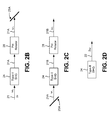
- FIGS. 2A-2D are diagrams showing an example implementation of a second harmonic generator 20 with a looped configuration for second harmonic generation.
- second harmonic generator 20 may include a second harmonic crystal 24 , a polarization filter 25 A, a polarization filter 25 B, a frequency filter 26 , a mirror 27 , and a polarization rotator 28 .
- Components of second harmonic generator 20 are described below, followed by a description of an example operation of second harmonic generator 20 .
- Second harmonic crystal 24 includes a component for generating a second harmonic optical beam.
- second harmonic crystal may include a crystal comprising Lithium Niobate or another type of non-linear crystal.
- second harmonic crystal 24 may perform Type-II conversion, whereby second harmonic crystal 24 uses photons in orthogonal polarizations for performing conversion to the second harmonic.
- a looped second harmonic generator may include a second harmonic crystal that performs Type-I conversion (e.g., whereby the second harmonic crystal uses photons in the same polarization for performing conversion to the second harmonic).
- second harmonic crystal 24 may be comprised of different materials depending on wavelength, power level, and/or one or more other parameters.
- Polarization filter 25 (e.g., polarization filter 25 A, polarization filter 25 B) includes a component for transmitting (T) a beam at a fundamental optical frequency ⁇ in a first polarization (e.g., a polarization that is parallel to the plane of the page in FIG. 2A , identified as a ⁇ polarization), and reflecting (R) a beam at a fundamental optical frequency ⁇ in a second polarization (e.g., a polarization that is orthogonal to the plane of the page in FIG. 2A , identified as a ⁇ polarization).
- polarization filter 25 may be referred to and/or identified as a ⁇ R ⁇ T filter.
- polarization filter 25 A may act as a polarizing combiner (e.g., a combiner that combines beams in different polarizations).
- a polarizing combiner e.g., a combiner that combines beams in different polarizations.
- the ⁇ polarization and the ⁇ polarization are provided as an example of orthogonal polarizations associated with performing Type-II conversion, and other orthogonal polarizations (e.g., not parallel or perpendicular to the plane of FIG. 2 ) may be used, in some implementations.
- Frequency filter 26 includes a component for reflecting (R) a beam at a fundamental (1) optical frequency ⁇ , and transmitting (T) a beam at a doubled (2) optical frequency 2 ⁇ .
- frequency filter 26 may be referred to and/or identified as a 1R2T filter.
- Mirror 27 includes a component for reflecting (R) a beam at a fundamental optical frequency ⁇ in any polarization (e.g., in the ⁇ polarization, in the ⁇ polarization, and/or the like). Thus, as shown in FIG. 2A , mirror 27 may be referred to and/or identified as a 1R mirror.
- Polarization rotator 28 includes a component for rotating a polarization of a beam (e.g., by 90°). For example, polarization rotator 28 may rotate a fundamental optical beam from the ⁇ polarization to the ⁇ polarization, and may rotate a fundamental optical beam from the ⁇ polarization to the ⁇ polarization, as described in further detail below.
- fundamental optical beam 21 (e.g., at the fundamental optical frequency ⁇ and in the ⁇ polarization) is launched toward the polarization filter 25 A.
- polarization filter 25 A combines fundamental optical beam 21 with residual fundamental optical beam 21 A (e.g., at the fundamental optical frequency ⁇ and in the ⁇ polarization), and fundamental optical beam 21 and residual fundamental optical beam 21 A are propagated to second harmonic crystal 24 .
- Second harmonic crystal 24 may be coupled to polarization filter 25 A for generating second harmonic optical beam 22 at the doubled optical frequency 2 ⁇ from fundamental optical beam 21 and residual fundamental optical beam 21 A.
- Second harmonic optical beam 22 is generated in second harmonic crystal 24 (e.g., using fundamental optical beam 21 and residual fundamental optical beam 21 A), and is directed to an output of second harmonic generator 20 .
- residual fundamental optical beam 21 A (e.g., an unconverted portion of fundamental optical beam 21 at the fundamental optical frequency ⁇ and in the ⁇ polarization) may exit second harmonic crystal 24 , and be directed, by frequency filter 26 and mirror 27 , through polarization rotator 28 such that residual fundamental optical beam 21 A is rotated to the ⁇ polarization.
- the polarization rotated residual fundamental optical beam 21 A may be directed by polarization filter 25 B to polarization filter 25 A for combining with fundamental optical beam 21 .
- residual fundamental optical beam 21 B (e.g., an unconverted portion of residual fundamental optical beam 21 A at the fundamental optical frequency ⁇ and in the ⁇ polarization) may exit second harmonic crystal 24 , and be directed, by frequency filter 26 and mirror 27 , through polarization rotator 28 such that residual fundamental optical beam 21 B is rotated to the ⁇ polarization.
- the polarization rotated residual fundamental optical beam 21 B is directed through polarization filter 25 B, where the polarization rotated residual fundamental optical beam 21 B may be absorbed by an optional optical beam dump (not shown).
- fundamental optical beam 21 (e.g., at fundamental optical frequency ⁇ and in the ⁇ polarization) propagates in sequence through second harmonic crystal 24 , then polarization rotator 28 as residual fundamental optical beam 21 A, and then is directed to polarization filter 25 A (e.g., at fundamental optical frequency ⁇ and in the ⁇ polarization).
- residual fundamental optical beam 21 A then propagates through second harmonic crystal 24 , then polarization rotator 28 as residual fundamental optical beam 21 B, and then is directed out of second harmonic generator 20 (e.g., at fundamental optical frequency ⁇ and in the ⁇ polarization) to, for example, an optional optical beam dump.
- second harmonic optical beam 22 is generated in second harmonic crystal 24 (e.g., using fundamental optical beam 21 and residual fundamental optical beam 21 A), and is directed to an output of second harmonic generator 20 .
- FIGS. 2A-2D The number and arrangement of components shown in FIGS. 2A-2D are provided as an example. In practice, there may be additional components, fewer components, different components, or differently arranged components than those shown in FIGS. 2A-2D .
- the second harmonic generation scheme shown in FIG. 2A uses a collinear phasematching technique
- one or more additional and/or different phasematching techniques may be implemented in second harmonic generator 20 , such as critical phasematching, noncritical phasematching, non-collinear phasematching, quasi-phase matching (e.g., using periodically-poled materials), and/or the like.
- such techniques are enabled due to the looped configuration of second harmonic generator 20 (e.g., since photons of a given photon pair, from which second harmonic optical beam 22 is generated, are from different optical beams), as described above.
- one or more types of components may be used (e.g., in addition to or in place of those shown in FIG. 2A ) to separate or combine optical beams within second harmonic generator 20 , such as dichroic or trichroic thin-film filters, polarization filters, absorptive filters, prisms, gratings, and/or other types of filters and/or mirrors. Additionally, or alternatively, various orderings and/or combinations of components (e.g., filters, crystals, mirrors, and/or the like) may be used in second harmonic generator 20 .
- one or more components may be included at appropriate locations in second harmonic generator 20 in order to provide a desired polarization state or a desired beam size and/or profile depending on specifics of the conversion configuration.
- two or more components shown in FIGS. 2A-2D may be implemented within a single component, or a single component shown in FIGS. 2A-2D may be implemented as multiple, distributed components. Additionally, or alternatively, a set of components (e.g., one or more components) of second harmonic generator 20 may perform one or more functions described as being performed by another set of second harmonic generator 20 .
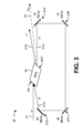
- FIG. 3 is a diagram showing another example implementation of a second harmonic generator 30 with a looped configuration for second harmonic generation.
- second harmonic generator 30 may include a second harmonic crystal 34 and a set of mirrors 37 A through 37 D. Components of second harmonic generator 30 are described below, followed by a description of an example operation of second harmonic generator 30 .
- Second harmonic crystal 34 includes a component for generating a second harmonic optical beam using photons in the same polarization or in perpendicular polarizations (i.e., a crystal for performing Type-I conversion or a crystal for performing Type-II conversion).
- second harmonic crystal 34 may be comprised of Lithium Niobate, or another type of non-linear crystal.
- second harmonic crystal 34 may include input optical face 34 I and output optical face 34 O slanted relative to fundamental optical beam 21 , residual fundamental optical beam 21 A, residual fundamental optical beam 21 B, and/or second harmonic optical beam 22 .
- input optical face 34 I and/or output optical face 34 O may be slanted at a Brewster angle relative to fundamental optical beam 21 , residual fundamental optical beam 21 A, residual fundamental optical beam 21 B, and/or second harmonic optical beam 23 .
- Mirror 37 (e.g., mirror 37 A, mirror 37 B, mirror 37 C, or mirror 37 D) includes a component for reflecting (R) a beam at a fundamental optical frequency ⁇ (e.g., in any polarization).
- ⁇ fundamental optical frequency
- mirror 37 may be referred to and/or identified as a 1R mirror.
- mirror 37 may be a regular mirror (i.e., not a dichroic mirror) since beam combining and splitting functions are provided by spatial multiplexing in second harmonic generator 30 (e.g., whereby a given beam is reflected by a mirror whereas another beam bypasses the mirror spatially).
- mirror 37 D may act as an angular combiner by steering residual fundamental optical beam 21 A toward second harmonic crystal 34 such that residual fundamental optical beam 21 A is combined with fundamental optical beam 21 (e.g., as described below).
- mirror 37 D may include a mirror, as indicated above, or another optical element that steers residual fundamental optical beam 21 A and/or fundamental optical beam 21 such that residual fundamental optical beam 21 A and fundamental optical beam 21 overlap (i.e., are combined) at second harmonic crystal 34 .
- mirror 37 D may include a prism, a grating, a lens, an optical fiber, and/or the like, that is arranged to steer residual fundamental optical beam 21 A and/or fundamental optical beam 21 .
- an input of fundamental optical beam 21 (e.g., at the fundamental optical frequency ⁇ ) is coupled to second harmonic crystal 34 .
- second harmonic crystal 34 is coupled to mirror 37 D such that residual fundamental optical beam 21 A (e.g., at the fundamental optical frequency ⁇ and identified as ⁇ ′ in FIG. 3 ) is combined with fundamental optical beam 21 at second harmonic crystal 34 .
- Second harmonic crystal 34 generates second harmonic optical beam 22 , at the doubled optical frequency 2 ⁇ , from fundamental optical beam 21 and residual fundamental optical beam 21 A, and second harmonic optical beam 22 is directed to an output of second harmonic generator 30 .
- residual fundamental optical beam 21 A (e.g., an unconverted portion of fundamental optical beam 21 ) may exit second harmonic crystal 34 . As shown, residual fundamental optical beam 21 A may be directed, via mirrors 37 A through 37 D, back to input optical face 34 I of second harmonic crystal 34 for combining with fundamental optical beam 21 .
- residual fundamental optical beam 21 B (e.g., an unconverted portion of residual fundamental optical beam 21 A at the fundamental optical frequency ⁇ and identified as ⁇ ′′ in FIG. 3 ) may exit second harmonic crystal 34 , and be directed out of second harmonic generator 30 to, for example, an optional optical beam dump (not shown).
- second harmonic optical beam 22 is generated in second harmonic crystal 34 (e.g., using fundamental optical beam 21 and residual fundamental optical beam 21 A), and is directed as an output of second harmonic generator 30 .
- second harmonic crystal 34 may be oriented such that fundamental optical beam 21 and residual fundamental optical beam 21 A impinge on the input optical face 34 I of second harmonic crystal 34 at a non-normal (e.g., acute) angle of incidence.
- fundamental optical beam 21 and residual fundamental optical beam 21 A may form a non-zero (acute) angle with respect to each other.
- fundamental optical beam 21 and residual fundamental optical beam 21 A may enter second harmonic crystal 34 at different angles, but at angles that are close enough to being parallel in order to ensure a sufficiently long interaction length within second harmonic crystal 34 (e.g., a length which may from less than 1 mm for a short-pulsed laser to several tens of mm for a continuous wave (CW) laser, where the length is typically limited by a practical fabrication length of second harmonic crystal 34 ).
- CW continuous wave
- fundamental optical beam 21 and residual fundamental optical beam 21 A are non-collinear, a non-collinear phasematching technique is used within second harmonic crystal 34 in order to provide efficient non-linear conversion.
- the angle between fundamental optical beam 21 and residual fundamental optical beam 21 A, and/or a relation of these angles to crystal axes of second harmonic crystal 34 may be chosen such that effective refractive indices, associated with fundamental optical beam 21 , residual fundamental optical beam 21 A, and second harmonic optical beam 22 , allow these optical beams to propagate in a correct phase relationship for efficient conversion.
- the adjustability of the angle between fundamental optical beam 21 and residual fundamental optical beam 21 A e.g., due to the use of the looped configuration
- these techniques may be used in conjunction with tuning using another technique, such as crystal temperature adjustment, tuning of beam angle with respect to the crystal axes, and/or the like.
- the refractive index in a particular crystal orientation is invariably different at the second harmonic optical frequency than at the fundamental optical frequency due to dispersion.
- the prior art second harmonic generator may not use a single polarization for both, and a mix of polarizations between input and output must be used.
- input beams can be angled in some second harmonic crystals such that phasematching can be achieved with both input (e.g., fundamental optical beam 21 and residual fundamental optical beam 21 A) and output (e.g., second harmonic optical beam 22 ) in the same polarization.
- the non-linear coefficient conversion rate of the second harmonic crystal depends on polarization orientations with respect to one another and to the crystal axes, this flexibility may allow stronger non-linear coefficients to be utilized, thereby increasing the conversion efficiency.
- a looped second harmonic generator may achieve increased conversion efficiency as compared to the prior art second harmonic generator.
- non-collinear phasematching may enable non-critical phasematching (e.g., when an output and its polarization are aligned with the crystal axes, and phasematching is first-order insensitive to crystal tilt) to be achieved in some second harmonic crystals.
- non-critical phasematching configuration may reduce an amount of beam walk-off and/or an amount of reduced angular sensitivity, for example, by accommodating an input beam with relatively high divergence.
- FIG. 4 is an example graphical representation 40 associated with an example of non-collinear phasematching enabled by a looped configuration for second harmonic generation (e.g., such as that shown in FIG. 3 ).
- FIG. 4 is a diagram illustrating ordinary refractive indices at 1064 nanometers (nm) (e.g., an IR wavelength) and extraordinary refractive indices at 532 nm (e.g., a green wavelength) across a temperature range from 0° C. to approximately 180° C. for a second harmonic crystal 34 formed from magnesium-doped Lithium Niobate.
- nm nanometers
- 532 nm e.g., a green wavelength
- this phasematching temperature may be reduced through use of non-collinear phasematching.
- a pair of beams at the IR wavelength e.g., fundamental optical beam 21 and residual fundamental optical beam 21 A
- these beams are incident on the second harmonic crystal at directions in the ordinary plane with an opening half-angle ⁇ .
- the refractive indices associated with the IR beams are ordinary n o1 and a refractive index, associated with a generated second harmonic optical beam at the green wavelength (e.g., second harmonic optical beam 22 ), is purely extraordinary n e2 .
- the non-collinearity enabled by the looped configuration can lower the ordinary refractive index, associated with the IR wavelength, to the extraordinary refractive index associated with the green wavelength.
- an approximate relationship between these indices may be represented by the following formula:
- n e2 n o1 ⁇ 1 ⁇ 3 ⁇ 10 ⁇ 5 ( T 0 ⁇ T ) ⁇ .
- ⁇ 2 6 ⁇ 10 ⁇ 5 ( T 0 ⁇ T ).
- FIG. 4 is provided merely as an example. Other examples are possible and may differ from what was described with regard to FIG. 4 .
- fundamental optical beam 21 may be polarized in the plane of FIG. 3 (e.g., ⁇ polarization), perpendicular to the plane of FIG. 3 (e.g., in the ⁇ ), at another angle with respect to the plane of FIG. 3 (e.g., at a 45° angle), and/or the like.
- second harmonic crystal 34 may be selected such that second harmonic crystal 34 performs Type-I conversion or Type-II conversion.
- second harmonic generator may include a polarization rotator (not shown) that rotates residual fundamental optical beam 21 A (e.g., by 90°) with respect to fundamental optical beam 21 .
- the looped configuration of second harmonic generator 30 may not require waveplates, dichroic mirrors, and/or the like, in order to separate residual fundamental optical beam 21 A and/or residual fundamental optical beam 21 B from second harmonic optical beam 22 . Rather, these beams may be spatially separated as indicated in FIG. 3 (e.g., such that mirrors 37 A through 37 D couple only residual fundamental optical beam 21 A to second harmonic crystal 34 ). In some implementations, when fundamental optical beam 21 and residual fundamental optical beam 21 A have different angles of incidence on input optical face 34 I of second harmonic crystal 34 , fundamental optical beam 21 and residual fundamental optical beam 21 A may be substantially non-collinear within second harmonic crystal 34 .
- the number and arrangement of components shown in FIG. 3 are provided as an example. In practice, there may be additional components, fewer components, different components, or differently arranged components than those shown in FIG. 3 .
- the second harmonic generation scheme shown in FIG. 3 uses a non-collinear phasematching technique with Type-I conversion
- one or more additional and/or different phasematching techniques may be implemented in second harmonic generator 30 , such as critical phasematching, noncritical phasematching, collinear phasematching, quasi-phase matching, and/or the like. In some implementations, such techniques are enabled due to the looped configuration of second harmonic generator 30 , as described above.
- various orderings and/or combinations of components e.g., filters, crystals, mirrors, and/or the like), may be used in second harmonic generator 20 .
- one or more components may be included at appropriate locations in second harmonic generator 30 in order to provide a desired polarization state or a desired beam size and/or profile depending on specifics of the conversion configuration.
- two or more components shown in FIG. 3 may be implemented within a single component, or a single component shown in FIG. 3 may be implemented as multiple, distributed components. Additionally, or alternatively, a set of components (e.g., one or more components) of second harmonic generator 30 may perform one or more functions described as being performed by another set of second harmonic generator 30 .
- the looped configurations described above may provide a higher efficiency conversion than the prior art second harmonic generator 10 of FIG. 1 .
- the second harmonic conversion efficiency depends on an input power density at the fundamental optical frequency ⁇ .
- the total power input to second harmonic crystal 14 is limited to the total power input P to prior art second harmonic generator 10 .
- the total optical power input to second harmonic crystal 24 / 34 (e.g., of second harmonic generator 20 and second harmonic generator 30 , respectively) is actually greater than P, because at least some of the power at ⁇ may be used twice (e.g., due to the looped configuration where residual fundamental optical beam 21 A is used along with fundamental optical beam 21 for generating second harmonic optical beam 22 ).
- the result is that the power density—and, therefore, the conversion efficiency—is higher in a looped second harmonic generator (e.g., second harmonic generator 20 , second harmonic generator 30 , and/or the like) than in prior art second harmonic generator 10 .
- optical paths of fundamental optical beam 21 and residual fundamental optical beam 21 A optical may be configured so as not to form a closed loop (i.e., an open loop) at individual optical frequencies, or an optical cavity at an individual optical frequency. Avoiding the closed loop or the optical cavity at individual optical frequencies may facilitate stability of the second harmonic generation process.
- second harmonic crystal 24 / 34 may utilize Brewster-angle entry and/or exit.
- Brewster-angle entry and/or exit may reduce surface loss on second harmonic crystal 24 / 34 (e.g., as an alternative to an anti-reflection (AR) coating, which can be damage-prone).
- AR anti-reflection
- Brewster surfaces are low-loss only for a particular polarization (e.g., for the p polarization, which may correspond to the ⁇ polarization described above).
- an angle-multiplexed second harmonic generation scheme e.g., such as that shown in FIG.
- these beams may have low surface loss when Brewster-angle entry and/or exit is utilized, which assists in achieving high conversion efficiency.
- an amount of surface loss is generally acceptable within a few degrees (e.g., 5° or less) of the optimal Brewster angle.
- Another benefit of using Brewster-angle entry and/or exit is that refraction at an output (e.g., at output optical face 34 O) may be used to separate second harmonic optical beam 22 from residual fundamental optical beam 21 A and residual fundamental optical beam 21 B (e.g., as shown in FIG. 3 ).
- Brewster entry and/or exit can also be used in systems where not all the beams are in the p polarization.
- a Type-II conversion scheme e.g., such as that shown in FIG. 2A
- one input and an output may be p-polarized, thereby having low surface loss on the second harmonic crystal.
- the other input may be s-polarized (e.g., which may correspond to the ⁇ polarization described above), and the corresponding loss may be accepted, or an AR coating, optimized for the s polarization, may be applied to second harmonic crystal.
- the s-polarized input may be residual fundamental optical beam 21 A (e.g., rather than fundamental optical beam 21 ), in order to cause surface loss occurs to occur only (e.g., at an input face of the second harmonic crystal) since loss of residual fundamental optical beam 21 A at an output face of the second harmonic crystal does not impact conversion efficiency.
- looped second harmonic generator e.g., second harmonic generator 20 , second harmonic generator 30 , and/or the like
- the position and angle of fundamental optical beam 21 and residual fundamental optical beam 21 A can be optimized for a specific conversion configuration by an adjustment of another component of the looped second harmonic generator (e.g., polarization filter 25 A, polarization filter 25 B, mirror 37 C, mirror 37 D, and/or the like).
- another component of the looped second harmonic generator e.g., polarization filter 25 A, polarization filter 25 B, mirror 37 C, mirror 37 D, and/or the like.
- a birefringent or dispersive walk-off plate may not be needed for walk-off compensation.
- a prism or other dispersive component may not be needed to create a desired angle between fundamental optical beam 21 and residual fundamental optical beam 21 A.
- this configuration may be adaptable for operation with input pulses that are longer in duration than the time required for light to travel around the loop.
- a dimension of such a loop may be, for example, one or more centimeters (e.g., 3 centimeters (cm)), corresponding to pulse duration on the order of approximately 100 picoseconds.
- the looped second harmonic conversion techniques described above may be well suited for laser systems generating nanosecond or longer pulses, for example Q-switched solid-state lasers, as well as CW lasers. Smaller loops addressing picosecond pulses (e.g., from mode-locked lasers) may be built using micro-optics of millimeter or smaller size.
- the looped configuration may also be used with multiple pulses, each of which has a pulse length that is shorter than the loop round-trip time, if the loop round-trip time is selected to be approximately equal to the pulse separation time, or a multiple of the pulse separation time.
- the input to second harmonic crystal 24 / 34 includes a new pulse and a pulse that was generated from an earlier pulse.
- a CW mode-locked laser may continuously deliver pulses of duration about 10 picoseconds or shorter at repetition rates in the range of tens of 1 MHz to 1 GHz.
- a looped second harmonic generator with a loop of round-trip time of 5 nanoseconds, corresponding to 150 cm total optical path length, would allow each pulse to be doubled using light from the preceding pulse.
- This configuration would provide the same benefits of improved conversion efficiency as in the case of a single longer pulse.
- a delay time (herein referred to as harmonic generator delay time) of a looped second harmonic generator may be designed to be approximately equal to, or an approximate integer multiple of, a round-trip time of a laser source (herein referred to as a laser source round-trip time).
- the delay time of the looped second harmonic generator may be designed such that the delay time is approximately equal to, or is an integer multiple of, a laser source round-trip time of a laser source that provides fundamental optical beam 21 .
- the delay time of a harmonic generator may be defined as an amount of time for a beam to travel through the harmonic generator.
- the delay time may also be considered as the optical path length travelled by the beam in the harmonic generator.
- the optical path length travelled is related to the physical separation of the components of the looped second harmonic generator and refractive indices of materials through which the beam passes.
- a round-trip time is a more specific case for a delay time where a start point and an end point are the same point.
- a round-trip time for a beam through second harmonic generator 20 may be defined as an amount of time from a time when fundamental optical beam 21 passes through polarization filter 25 A to a time at which residual fundamental optical beam 21 A, originating from that fundamental optical beam 21 , reaches the same polarization filter 25 A.
- Other points in the optical path where residual fundamental optical beam 21 A (or 21 B) overlaps fundamental optical beam 21 (or 21 A) may be used to define the round-trip time for a beam in second harmonic generator 20 .
- a round-trip time for a beam through second harmonic generator 30 may be defined as an amount of time from a time when fundamental optical beam 21 is incident on input optical face 34 I of second harmonic crystal 34 to a time at which residual fundamental optical beam 21 A, originating from that fundamental optical beam 21 , reaches input optical face 34 I of second harmonic crystal 34 .
- Other points in the optical path where residual fundamental optical beam 21 A (or 21 B) overlaps fundamental optical beam 21 (or 21 A) may be used to define the round-trip time for a beam in second harmonic generator 30 .
- the laser source round-trip time may be defined as an amount of time for a beam of light to traverse a cavity of the laser source fully, so as to end up traveling in the same direction as at the outset.
- the laser source round-trip time is an amount of time for a beam to travel from a particular point within the cavity, reflect from one cavity end mirror, reflect from the other cavity end mirror, and travel back to the same particular point within the cavity, in the process also twice traversing the laser gain medium or media.
- fluctuations of the laser source approximately repeat on successive round-trips associated with the laser source.
- a laser source of fundamental optical beam 21 may operate in a multi-longitudinal mode.
- power of the laser source may fluctuate due to mode beating.
- such fluctuations occur on a picosecond timescale and, on the picosecond timescale, the power output may vary from near zero to multiple times an average power output. Since a laser source round-trip time may be several nanoseconds, there may be thousands of fluctuations during a given round-trip of the laser source, causing noise to be introduced into the optical beam output by the laser source.
- the typical standard non-linear second harmonic conversion scheme may benefit from these fluctuations, particularly in the low conversion limit.
- high-power fluctuations of the fundamental optical beam 11 convert strongly to second harmonic beam 12 .
- the non-linear nature of this coupling implies that an average power conversion is increased more by the high-power fluctuations than the average power conversion is decreased by relatively low-power fluctuations.
- second harmonic crystal 24 / 34 In the looped second harmonic generator, second harmonic crystal 24 / 34 generates second harmonic optical beam 22 based on a combination of fundamental optical beam 21 and residual fundamental optical beam 21 A.
- residual fundamental optical beam 21 A travels a different optical path from fundamental optical beam 21 prior to entering second harmonic crystal 24 / 34 , fluctuations in fundamental optical beam 21 and fluctuations in residual fundamental optical beam 21 A may not be synchronized (i.e., may be temporally misaligned) when entering second harmonic crystal 24 / 34 , which prevents enhancement of power conversion from the fluctuations.
- second harmonic crystal 24 / 34 receives fundamental optical beam 21 directly from the laser source, and receives residual fundamental optical beam 21 A via the looped optical path. Accordingly, it is possible that fundamental optical beam 21 and residual fundamental optical beam 21 A received by second harmonic generator 24 / 34 may be unsynchronized, which may reduce generation of second harmonic beam 22 .
- the fluctuations of the laser source approximately repeat on successive round-trips associated with the laser source.
- a gradual change of a waveform of the fluctuations may exist (e.g., on a timescale from tens to hundreds of round-trips)
- a change in the waveform of the fluctuations from one laser source round-trip (e.g., a first round-trip) to a temporally close round-trip (e.g., a second round-trip, a third round-trip, or a fourth round-trip) is small, which causes the waveforms to be nearly periodic.
- the power conversion enhancement may be obtained by designing the delay time of the looped second harmonic generator (e.g., T HG ) to be approximately equal to, or an approximate integer multiple of, the laser source round-trip time (e.g., T source ).
- the delay time of the looped second harmonic generator e.g., T HG
- the laser source round-trip time e.g., T source
- fundamental optical beam 21 and residual fundamental optical beam 21 A may not be exactly aligned when entering second harmonic crystal 24 / 34
- the fluctuations may be approximately synchronized due to the near-periodic nature of the fluctuation waveform.
- the delay time of the looped second harmonic generator may be designed based on a layout of the looped second harmonic generator.
- one or more components of the looped second harmonic generator e.g., second harmonic crystal 24 / 34 , polarization filter 25 A, polarization filter 25 B, frequency filter 26 , mirror 27 / 37 , polarization rotator 28 , and/or the like
- one or more components of the looped second harmonic generator may be positioned (e.g., glued, soldered, bolted) such that distances between the one or more components cause the non-linear optical loop length to match (i.e., be approximately equal to or be an approximate integer multiple of) the round-trip optical path length of the laser source, thereby causing the delay time of the looped second harmonic generator to be approximately equal to, or an approximate integer multiple of, the laser source round-trip time.
- the delay time of the looped second harmonic generator may be designed based on positioning of the one or more components of the looped second harmonic generator.
- the delay time design of the looped second harmonic generator may be implemented using a linear build process.
- the linear build process may include manufacturing the laser source before placing components of the looped second harmonic generator (e.g., within a package that houses the laser source and the looped second harmonic generator).
- a mode beating period of the laser source may be locked (e.g., throughout life of the laser source) after the laser source is manufactured, while a mode beating period of another laser source (e.g., manufactured at another time) may be different than that of the laser source.
- mode beating periods of different laser sources may vary slightly.
- the round-trip optical path length of the laser source may vary from one laser source to another.
- the linear build process may further include determining the round-trip optical path length of the laser source, determining a non-linear optical path length that matches the round-trip optical path length of the laser source (e.g., when indices of diffraction of materials of components of the looped second harmonic generator are taken into account), and placing and/or manufacturing components of the looped second harmonic generator such that the non-linear optical path length of the looped second harmonic generator matches the round-trip optical path length of the laser source, thereby causing the delay time of the looped second harmonic generator to be approximately equal to, or an approximate integer multiple of, the laser source round-trip time.
- the components of the looped second harmonic generator are fixed in place (e.g., the components may be glued in place, soldered in place, bolted in place, or the like) such that the non-linear optical path and the delay time of the looped second harmonic generator are non-adjustable (i.e., fixed).
- the delay time design of the looped second harmonic generator may be implemented using an adjustable mechanical component such as a micrometer, a rotary stage, or an adjustable mirror mount that moves one or more optical components within the non-linear optical path, for example a mirror or a prism, thereby allowing the delay time of the non-linear optical path to be adjusted.
- the inclusion of the adjustable component may allow the non-linear optical path length to be modified after assembly within the package that houses the laser source and the looped second harmonic generator. In such a case, the laser source and the looped second harmonic generator may be assembled within the package before the round-trip optical path length of the laser source is determined.
- the round-trip optical path length of the laser source may be determined, the non-linear optical path length that matches the round-trip optical path length of the laser source may be determined, and the non-linear optical path of the looped second harmonic generator may be adjusted, using the adjustable component, accordingly.
- FIG. 5 is a flow chart of an example process 50 for second harmonic optical generation using a looped configuration, as described herein.
- example process 50 may be performed by a looped second harmonic generator, such as second harmonic generator 20 , second harmonic generator 30 , and/or the like.
- process 50 may include propagating a fundamental optical beam through a second harmonic crystal to generate a second harmonic optical beam from the fundamental optical beam and a residual fundamental optical beam (block 51 ).
- the looped second harmonic generator may propagate a fundamental optical beam through a second harmonic crystal to generate a second harmonic optical beam from the fundamental optical beam and a residual fundamental optical beam, as described above in connection with second harmonic generator 20 and second harmonic generator 30 .
- the residual fundamental optical beam may exit the second harmonic crystal, as described above in connection with second harmonic generator 20 and second harmonic generator 30 .
- process 50 may include propagating the residual fundamental optical beam such that the residual fundamental optical beam enters the second harmonic crystal with the fundamental optical beam so as to generate the second harmonic optical beam (block 52 ).
- the looped second harmonic generator may propagate the residual fundamental optical beam such that the residual fundamental optical beam enters the second harmonic crystal with the fundamental optical beam so as to generate the second harmonic optical beam, as described above in connection with second harmonic generator 20 and second harmonic generator 30 .
- process 50 may include additional blocks, fewer blocks, different blocks, or differently arranged blocks than those depicted in FIG. 5 . Additionally, or alternatively, two or more of the blocks of process 50 may be performed in parallel.
- the looped configuration enables opportunities for a non-linear strength conversion rate to be improved and/or optimized through selection of crystal orientation, polarization orientation, phasematching type, and/or the like. Further, the looped configuration enables opportunities for improving and/or optimizing an output beam quality, an acceptance bandwidth, an angular acceptance, and/or the like, through the use more easily achieved non-critical phasematching (e.g., as compared to the prior art second harmonic generator). Further, the looped configuration for second harmonic generation improves conversion efficiency of the second harmonic generator (e.g., as compared to the prior art second harmonic generator).
Landscapes
- Physics & Mathematics (AREA)
- Nonlinear Science (AREA)
- Optics & Photonics (AREA)
- General Physics & Mathematics (AREA)
- Electromagnetism (AREA)
- Chemical & Material Sciences (AREA)
- Crystallography & Structural Chemistry (AREA)
- Engineering & Computer Science (AREA)
- Plasma & Fusion (AREA)
- Optical Modulation, Optical Deflection, Nonlinear Optics, Optical Demodulation, Optical Logic Elements (AREA)
Abstract
Description
- This application is a Continuation-In-Part (CIP) of U.S. patent application Ser. No. 15/429,804, filed on Feb. 10, 2017, which is a Continuation of U.S. patent application Ser. No. 15/177,140, filed on Jun. 8, 2016 (now U.S. Pat. No. 9,568,803), which is a CIP of U.S. patent application Ser. No. 14/719,617, filed on May 22, 2015 (now U.S. Pat. No. 9,377,667), which claims priority to U.S. Provisional Application No. 62/002,006, filed May 22, 2014, the contents of which are incorporated by reference herein in their entirety.
- The present disclosure relates to second harmonic generation and, more particularly, to devices and methods for second harmonic generation using a looped configuration.
- Optical harmonic generation may be used to convert laser light from one wavelength to a shorter wavelength (i.e., a higher frequency). For example, frequency doubling, or second harmonic generation (SHG), may be used to obtain visible light from near infrared light. The frequency doubled light may then be used for generating frequency tripled light, spectroscopy, materials processing, optical pumping, and/or the like.
- Typically, the optical frequency of laser light is doubled using a nonlinear optical crystal that uses a single input beam to provide a pair of photons required for conversion to the second harmonic.
FIG. 1 is a diagram illustrating a prior art secondharmonic generator 10. As shown inFIG. 1 , prior art secondharmonic generator 10 includes secondharmonic crystal 14. In operation, fundamentaloptical beam 11 at optical frequency ω impinges on secondharmonic crystal 14. Since a nonlinear conversion efficiency of secondharmonic crystal 14 is less than 100%, only a portion of fundamentaloptical beam 11 is frequency doubled within secondharmonic crystal 14, so that secondharmonic beam 12 at a second harmonic frequency 2ω exits secondharmonic crystal 14 together with anunconverted portion 11A of fundamentaloptical beam 11 at optical frequency ω. Thus, two beams exit second harmonic crystal 14:unconverted portion 11A of fundamentaloptical beam 11 and secondharmonic beam 12. In some applications, secondharmonic beam 12 andunconverted portion 11A may impinge on a third harmonic crystal (not shown), which converts a portion of these beams into a third harmonic beam at a third harmonic frequency. Alternatively, in some cases, secondharmonic beam 12 may be propagated for another purpose. For example, prior art secondharmonic generator 10 may include a dichroic mirror (or filter) that redirectsunconverted portion 11A and transmits secondharmonic beam 12 as an output. - According to some possible implementations, a second harmonic generator, may include: a combiner to combine a fundamental optical beam with a residual fundamental optical beam; and a second harmonic crystal, coupled to the combiner, to generate a second harmonic optical beam from the fundamental optical beam and the residual fundamental optical beam, wherein, upon generation of the second harmonic optical beam, the residual fundamental optical beam may exit the second harmonic crystal.
- According to some possible implementations, a method may include: propagating, by a second harmonic generator, a fundamental optical beam through a second harmonic crystal to generate a second harmonic optical beam from the fundamental optical beam and a residual fundamental optical beam, wherein, upon generation of the second harmonic optical beam, the residual fundamental optical beam may exit the second harmonic crystal; and propagating, by the second harmonic generator, the residual fundamental optical beam such that the residual fundamental optical beam enters the second harmonic crystal with the fundamental optical beam so as to generate the second harmonic optical beam.
- According to some possible implementations, a laser may include: a combiner to combine a fundamental optical beam with a residual fundamental optical beam; a second harmonic crystal to generate a second harmonic optical beam from the fundamental optical beam and the residual fundamental optical beam, wherein, upon generation of the second harmonic optical beam, the residual fundamental optical beam may exit the second harmonic crystal; and one or more optical components to direct the residual fundamental optical beam to the combiner.
-
FIG. 1 illustrates a schematic block diagram of a prior art second harmonic generator; -
FIGS. 2A-2D are diagrams showing an example implementation of a second harmonic generator with a looped configuration for second harmonic generation; -
FIG. 3 is a diagram showing another example implementation of a second harmonic generator with a looped configuration for second harmonic generation; -
FIG. 4 is an example graphical representation associated with an example of non-collinear phasematching enabled by a looped configuration for second harmonic generation; and -
FIG. 5 is a flow chart of an example process for second harmonic optical generation using a looped configuration, as described herein. - While the present teachings are described in conjunction with various embodiments and examples, it is not intended that the present teachings be limited to such embodiments. On the contrary, the present teachings encompass various alternatives and equivalents, as will be appreciated by those of skill in the art.
- A typical prior art second harmonic generation scheme, such as that illustrated by prior art second
harmonic generator 10 ofFIG. 1 , uses Type-I collinear second harmonic generation. Here, fundamental photons to be combined are identical photons within a single incoming beam (e.g., fundamental optical beam 11). In Type-II second harmonic generation, each second-harmonic photon is formed from a pair of fundamental photons in linear polarization states that are orthogonal to one another. Thus, the input optical beam may be, for example, a single circularly-polarized beam or a single linearly-polarized beam oriented at 45° to two linear states to be combined in the second harmonic generator (in either case providing equal numbers of photons in each orthogonal polarization). - In addition to being Type-I phasematching or Type-II phasematching, phasematching can be critical or non-critical. Non-critical phasematching has well-known advantages regarding walk-off and angular sensitivity. However, non-critical phasematching may be difficult to achieve in a prior art second harmonic generation configuration (e.g., such as that shown in
FIG. 1 ) since non-critical phasematching relies on precise coincidences of refractive indices associated with a non-linear crystal material, generally assisted by temperature tuning. Further, in the prior art second harmonic generation configuration non-collinear phasematching is not possible (e.g., since both incoming photons are in the same fundamental optical beam). As a result of these constraints, for a given non-linear crystal, there is little opportunity to improve and/or optimize a non-linear strength conversion rate through selection of crystal orientation, polarization orientation, or phasematching type, or to improve and/or optimize an output beam quality, an acceptance bandwidth, an angular acceptance, and/or the like, through the use of non-critical phasematching. - Another drawback of the prior art second harmonic generator is that tight focusing of the fundamental optical beam into the second harmonic crystal is typically required in order to obtain a reasonable conversion efficiency. Such tight focusing results in a small spot diameter of the fundamental optical beam that may compromise beam quality (e.g., due to a beam walk-off effect). Further, tight focusing of the fundamental optical beam may result in degradation of a surface of the second harmonic crystal 14 (e.g., after tens or hundreds of hours of exposure).
- Some implementations described herein provide a second harmonic generator that uses a looped configuration for second harmonic generation. In some implementations, the looped configuration enables opportunities for a non-linear strength conversion rate to be improved and/or optimized through selection of crystal orientation, polarization orientation, phasematching type, and/or the like. Further, the looped configuration enables opportunities for improving and/or optimizing an output beam quality, an acceptance bandwidth, an angular acceptance, and/or the like, through the use non-critical phasematching (e.g., as compared to the prior art second harmonic generator). Further, the looped configuration for second harmonic generation improves conversion efficiency of the second harmonic generator (e.g., as compared to the prior art second harmonic generator).
-
FIGS. 2A-2D are diagrams showing an example implementation of a secondharmonic generator 20 with a looped configuration for second harmonic generation. - As shown in
FIG. 2A , secondharmonic generator 20 may include a secondharmonic crystal 24, apolarization filter 25A, apolarization filter 25B, afrequency filter 26, amirror 27, and apolarization rotator 28. Components of secondharmonic generator 20 are described below, followed by a description of an example operation of secondharmonic generator 20. - Second harmonic crystal 24 includes a component for generating a second harmonic optical beam. For example, second harmonic crystal may include a crystal comprising Lithium Niobate or another type of non-linear crystal. Notably, in second
harmonic generator 20, secondharmonic crystal 24 may perform Type-II conversion, whereby second harmonic crystal 24 uses photons in orthogonal polarizations for performing conversion to the second harmonic. However, in some implementations, as described below in connection withFIG. 3 , a looped second harmonic generator may include a second harmonic crystal that performs Type-I conversion (e.g., whereby the second harmonic crystal uses photons in the same polarization for performing conversion to the second harmonic). In some implementations, secondharmonic crystal 24 may be comprised of different materials depending on wavelength, power level, and/or one or more other parameters. - Polarization filter 25 (e.g.,
polarization filter 25A,polarization filter 25B) includes a component for transmitting (T) a beam at a fundamental optical frequency ω in a first polarization (e.g., a polarization that is parallel to the plane of the page inFIG. 2A , identified as a ∥ polarization), and reflecting (R) a beam at a fundamental optical frequency ω in a second polarization (e.g., a polarization that is orthogonal to the plane of the page inFIG. 2A , identified as a ⊥ polarization). Thus as shown inFIG. 2A , polarization filter 25 may be referred to and/or identified as a ⊥R∥T filter. By transmitting the fundamental optical beam in the ∥ polarization and reflecting the fundamental optical beam in the ⊥ polarization,polarization filter 25A may act as a polarizing combiner (e.g., a combiner that combines beams in different polarizations). Notably, the ∥ polarization and the ⊥ polarization are provided as an example of orthogonal polarizations associated with performing Type-II conversion, and other orthogonal polarizations (e.g., not parallel or perpendicular to the plane ofFIG. 2 ) may be used, in some implementations. -
Frequency filter 26 includes a component for reflecting (R) a beam at a fundamental (1) optical frequency ω, and transmitting (T) a beam at a doubled (2) optical frequency 2ω. Thus, as shown inFIG. 2A ,frequency filter 26 may be referred to and/or identified as a 1R2T filter. -
Mirror 27 includes a component for reflecting (R) a beam at a fundamental optical frequency ω in any polarization (e.g., in the ⊥ polarization, in the ∥ polarization, and/or the like). Thus, as shown inFIG. 2A ,mirror 27 may be referred to and/or identified as a 1R mirror. -
Polarization rotator 28 includes a component for rotating a polarization of a beam (e.g., by 90°). For example,polarization rotator 28 may rotate a fundamental optical beam from the ∥ polarization to the ⊥ polarization, and may rotate a fundamental optical beam from the ⊥ polarization to the ∥ polarization, as described in further detail below. - In operation of second
harmonic generator 20, fundamental optical beam 21 (e.g., at the fundamental optical frequency ω and in the ∥ polarization) is launched toward thepolarization filter 25A. As shown,polarization filter 25A combines fundamentaloptical beam 21 with residual fundamentaloptical beam 21A (e.g., at the fundamental optical frequency ω and in the ⊥ polarization), and fundamentaloptical beam 21 and residual fundamentaloptical beam 21A are propagated to secondharmonic crystal 24. Secondharmonic crystal 24 may be coupled topolarization filter 25A for generating second harmonicoptical beam 22 at the doubled optical frequency 2ω from fundamentaloptical beam 21 and residual fundamentaloptical beam 21A. Second harmonicoptical beam 22 is generated in second harmonic crystal 24 (e.g., using fundamentaloptical beam 21 and residual fundamentaloptical beam 21A), and is directed to an output of secondharmonic generator 20. - Upon generation of second harmonic
optical beam 22, residual fundamentaloptical beam 21A (e.g., an unconverted portion of fundamentaloptical beam 21 at the fundamental optical frequency ω and in the ∥ polarization) may exit secondharmonic crystal 24, and be directed, byfrequency filter 26 andmirror 27, throughpolarization rotator 28 such that residual fundamentaloptical beam 21A is rotated to the ⊥ polarization. As shown, the polarization rotated residual fundamentaloptical beam 21A may be directed bypolarization filter 25B topolarization filter 25A for combining with fundamentaloptical beam 21. - Further, upon generation of second harmonic
optical beam 22, residual fundamentaloptical beam 21B (e.g., an unconverted portion of residual fundamentaloptical beam 21A at the fundamental optical frequency ω and in the ⊥ polarization) may exit secondharmonic crystal 24, and be directed, byfrequency filter 26 andmirror 27, throughpolarization rotator 28 such that residual fundamentaloptical beam 21B is rotated to the ∥ polarization. As shown, the polarization rotated residual fundamentaloptical beam 21B is directed throughpolarization filter 25B, where the polarization rotated residual fundamentaloptical beam 21B may be absorbed by an optional optical beam dump (not shown). - The optical paths of fundamental
optical beam 21, residual fundamentaloptical beam 21A, residual fundamentaloptical beam 21B, and second harmonicoptical beam 22 are further shown byFIGS. 2B-2D . As shown inFIG. 2B , fundamental optical beam 21 (e.g., at fundamental optical frequency ω and in the ∥ polarization) propagates in sequence through secondharmonic crystal 24, thenpolarization rotator 28 as residual fundamentaloptical beam 21A, and then is directed to polarization filter 25A (e.g., at fundamental optical frequency ω and in the ⊥ polarization). - As shown in
FIG. 2C , residual fundamentaloptical beam 21A then propagates through secondharmonic crystal 24, thenpolarization rotator 28 as residual fundamentaloptical beam 21B, and then is directed out of second harmonic generator 20 (e.g., at fundamental optical frequency ω and in the ∥ polarization) to, for example, an optional optical beam dump. - As shown in
FIG. 2D , second harmonicoptical beam 22 is generated in second harmonic crystal 24 (e.g., using fundamentaloptical beam 21 and residual fundamentaloptical beam 21A), and is directed to an output of secondharmonic generator 20. - The number and arrangement of components shown in
FIGS. 2A-2D are provided as an example. In practice, there may be additional components, fewer components, different components, or differently arranged components than those shown inFIGS. 2A-2D . For example, while the second harmonic generation scheme shown inFIG. 2A uses a collinear phasematching technique, in some implementations, one or more additional and/or different phasematching techniques may be implemented in secondharmonic generator 20, such as critical phasematching, noncritical phasematching, non-collinear phasematching, quasi-phase matching (e.g., using periodically-poled materials), and/or the like. In some implementations, such techniques are enabled due to the looped configuration of second harmonic generator 20 (e.g., since photons of a given photon pair, from which second harmonicoptical beam 22 is generated, are from different optical beams), as described above. - Further, in some implementations, one or more types of components (e.g., mirrors, filters, and/or the like) may be used (e.g., in addition to or in place of those shown in
FIG. 2A ) to separate or combine optical beams within secondharmonic generator 20, such as dichroic or trichroic thin-film filters, polarization filters, absorptive filters, prisms, gratings, and/or other types of filters and/or mirrors. Additionally, or alternatively, various orderings and/or combinations of components (e.g., filters, crystals, mirrors, and/or the like) may be used in secondharmonic generator 20. - Additionally, while not shown in
FIGS. 2A-2D , in some implementations, one or more components (e.g., in addition to or in place of those shown inFIG. 2A ), such as one or more waveplates, non-planar beam paths, lenses, and/or the like, may be included at appropriate locations in secondharmonic generator 20 in order to provide a desired polarization state or a desired beam size and/or profile depending on specifics of the conversion configuration. - Furthermore, two or more components shown in
FIGS. 2A-2D may be implemented within a single component, or a single component shown inFIGS. 2A-2D may be implemented as multiple, distributed components. Additionally, or alternatively, a set of components (e.g., one or more components) of secondharmonic generator 20 may perform one or more functions described as being performed by another set of secondharmonic generator 20. -
FIG. 3 is a diagram showing another example implementation of a secondharmonic generator 30 with a looped configuration for second harmonic generation. - As shown in
FIG. 3 , secondharmonic generator 30 may include a secondharmonic crystal 34 and a set ofmirrors 37A through 37D. Components of secondharmonic generator 30 are described below, followed by a description of an example operation of secondharmonic generator 30. - Second
harmonic crystal 34 includes a component for generating a second harmonic optical beam using photons in the same polarization or in perpendicular polarizations (i.e., a crystal for performing Type-I conversion or a crystal for performing Type-II conversion). In some implementations, secondharmonic crystal 34 may be comprised of Lithium Niobate, or another type of non-linear crystal. - As shown in
FIG. 3 , in some implementations, secondharmonic crystal 34 may include input optical face 34I and output optical face 34O slanted relative to fundamentaloptical beam 21, residual fundamentaloptical beam 21A, residual fundamentaloptical beam 21B, and/or second harmonicoptical beam 22. For example, in some implementations, input optical face 34I and/or output optical face 34O may be slanted at a Brewster angle relative to fundamentaloptical beam 21, residual fundamentaloptical beam 21A, residual fundamentaloptical beam 21B, and/or second harmonic optical beam 23. - Mirror 37 (e.g.,
mirror 37A,mirror 37B,mirror 37C, ormirror 37D) includes a component for reflecting (R) a beam at a fundamental optical frequency ω (e.g., in any polarization). Thus, as shown inFIG. 3 , mirror 37 may be referred to and/or identified as a 1R mirror. In some implementations, mirror 37 may be a regular mirror (i.e., not a dichroic mirror) since beam combining and splitting functions are provided by spatial multiplexing in second harmonic generator 30 (e.g., whereby a given beam is reflected by a mirror whereas another beam bypasses the mirror spatially). In some implementations,mirror 37D may act as an angular combiner by steering residual fundamentaloptical beam 21A toward secondharmonic crystal 34 such that residual fundamentaloptical beam 21A is combined with fundamental optical beam 21 (e.g., as described below). In some implementations,mirror 37D may include a mirror, as indicated above, or another optical element that steers residual fundamentaloptical beam 21A and/or fundamentaloptical beam 21 such that residual fundamentaloptical beam 21A and fundamentaloptical beam 21 overlap (i.e., are combined) at secondharmonic crystal 34. For example, in some implementations,mirror 37D may include a prism, a grating, a lens, an optical fiber, and/or the like, that is arranged to steer residual fundamentaloptical beam 21A and/or fundamentaloptical beam 21. - In operation, an input of fundamental optical beam 21 (e.g., at the fundamental optical frequency ω) is coupled to second
harmonic crystal 34. As further shown, secondharmonic crystal 34 is coupled to mirror 37D such that residual fundamentaloptical beam 21A (e.g., at the fundamental optical frequency ω and identified as ω′ inFIG. 3 ) is combined with fundamentaloptical beam 21 at secondharmonic crystal 34. Secondharmonic crystal 34 generates second harmonicoptical beam 22, at the doubled optical frequency 2ω, from fundamentaloptical beam 21 and residual fundamentaloptical beam 21A, and second harmonicoptical beam 22 is directed to an output of secondharmonic generator 30. - Upon generation of second harmonic
optical beam 22, residual fundamentaloptical beam 21A (e.g., an unconverted portion of fundamental optical beam 21) may exit secondharmonic crystal 34. As shown, residual fundamentaloptical beam 21A may be directed, viamirrors 37A through 37D, back to input optical face 34I of secondharmonic crystal 34 for combining with fundamentaloptical beam 21. - Further, upon generation of second harmonic
optical beam 22, residual fundamentaloptical beam 21B (e.g., an unconverted portion of residual fundamentaloptical beam 21A at the fundamental optical frequency ω and identified as ω″ inFIG. 3 ) may exit secondharmonic crystal 34, and be directed out of secondharmonic generator 30 to, for example, an optional optical beam dump (not shown). - As described above, second harmonic
optical beam 22 is generated in second harmonic crystal 34 (e.g., using fundamentaloptical beam 21 and residual fundamentaloptical beam 21A), and is directed as an output of secondharmonic generator 30. - As shown in
FIG. 3 , in some implementations, secondharmonic crystal 34 may be oriented such that fundamentaloptical beam 21 and residual fundamentaloptical beam 21A impinge on the input optical face 34I of secondharmonic crystal 34 at a non-normal (e.g., acute) angle of incidence. In some implementations, fundamentaloptical beam 21 and residual fundamentaloptical beam 21A may form a non-zero (acute) angle with respect to each other. - Thus, in some implementations, fundamental
optical beam 21 and residual fundamentaloptical beam 21A may enter secondharmonic crystal 34 at different angles, but at angles that are close enough to being parallel in order to ensure a sufficiently long interaction length within second harmonic crystal 34 (e.g., a length which may from less than 1 mm for a short-pulsed laser to several tens of mm for a continuous wave (CW) laser, where the length is typically limited by a practical fabrication length of second harmonic crystal 34). Here, since fundamentaloptical beam 21 and residual fundamentaloptical beam 21A are non-collinear, a non-collinear phasematching technique is used within secondharmonic crystal 34 in order to provide efficient non-linear conversion. For example, the angle between fundamentaloptical beam 21 and residual fundamentaloptical beam 21A, and/or a relation of these angles to crystal axes of secondharmonic crystal 34, may be chosen such that effective refractive indices, associated with fundamentaloptical beam 21, residual fundamentaloptical beam 21A, and second harmonicoptical beam 22, allow these optical beams to propagate in a correct phase relationship for efficient conversion. In some implementations, the adjustability of the angle between fundamentaloptical beam 21 and residual fundamentaloptical beam 21A (e.g., due to the use of the looped configuration) for achieving phasematching provides greater flexibility in selecting a phasematching configuration, a crystal type of secondharmonic crystal 34, and/or the like, in order to improve and/or optimize conversion efficiency and/or one or more other characteristics. In some implementations, these techniques may be used in conjunction with tuning using another technique, such as crystal temperature adjustment, tuning of beam angle with respect to the crystal axes, and/or the like. - As a particular example, in a prior art second harmonic generator that uses conventional collinear phasematching (e.g., second harmonic generator 10) the refractive index in a particular crystal orientation is invariably different at the second harmonic optical frequency than at the fundamental optical frequency due to dispersion. Thus, the prior art second harmonic generator may not use a single polarization for both, and a mix of polarizations between input and output must be used. However, with non-collinear phasematching, input beams can be angled in some second harmonic crystals such that phasematching can be achieved with both input (e.g., fundamental
optical beam 21 and residual fundamentaloptical beam 21A) and output (e.g., second harmonic optical beam 22) in the same polarization. Here, because the non-linear coefficient conversion rate of the second harmonic crystal depends on polarization orientations with respect to one another and to the crystal axes, this flexibility may allow stronger non-linear coefficients to be utilized, thereby increasing the conversion efficiency. Thus, by enabling non-collinear phasematching, a looped second harmonic generator may achieve increased conversion efficiency as compared to the prior art second harmonic generator. - As another particular example of the utility of non-collinear phasematching enabled by the looped configuration for second harmonic generation, non-collinear phasematching may enable non-critical phasematching (e.g., when an output and its polarization are aligned with the crystal axes, and phasematching is first-order insensitive to crystal tilt) to be achieved in some second harmonic crystals. In some implementations, such a non-critical phasematching configuration may reduce an amount of beam walk-off and/or an amount of reduced angular sensitivity, for example, by accommodating an input beam with relatively high divergence.
-
FIG. 4 is an examplegraphical representation 40 associated with an example of non-collinear phasematching enabled by a looped configuration for second harmonic generation (e.g., such as that shown inFIG. 3 ).FIG. 4 is a diagram illustrating ordinary refractive indices at 1064 nanometers (nm) (e.g., an IR wavelength) and extraordinary refractive indices at 532 nm (e.g., a green wavelength) across a temperature range from 0° C. to approximately 180° C. for a secondharmonic crystal 34 formed from magnesium-doped Lithium Niobate. - As show by
FIG. 4 , a temperature where these indices are equal, and therefore phasematched, is approximately 110° C. (T0=110° C.). In this example, this phasematching temperature may be reduced through use of non-collinear phasematching. For example, due to the use of the looped configuration, a pair of beams at the IR wavelength (e.g., fundamentaloptical beam 21 and residual fundamentaloptical beam 21A) may be directed such that these beams are incident on the second harmonic crystal at directions in the ordinary plane with an opening half-angle φ. The refractive indices associated with the IR beams are ordinary no1 and a refractive index, associated with a generated second harmonic optical beam at the green wavelength (e.g., second harmonic optical beam 22), is purely extraordinary ne2. Here, phasematching is represented by an equality of a green wavevector to a sum of two IR wavevectors and, thus, ne2=no1 cos φ. For temperatures below T0, the non-collinearity enabled by the looped configuration can lower the ordinary refractive index, associated with the IR wavelength, to the extraordinary refractive index associated with the green wavelength. For example, an approximate relationship between these indices may be represented by the following formula: -
n e2 =n o1└1−3×10⁻⁵(T 0 −T)┘. - Setting this formula to be equal to the non-collinear ne2=no1 cos φ≈n01(1−φ2/2), the following formula is derived:
-
φ2=6×10⁻⁵(T 0 −T). - Therefore, in order to operate at, for example, a temperature of approximately 30° (T=30°), the above formula can be evaluated to yield φ=0.07 radians, which corresponds to a 4° half angle, or an 8° full angle, between the two IR beams. In this way, non-collinear phasematching may enable non-critical phasematching to be more readily achieved, thereby enabling additional phasematching configurations to be considered for implementation in the looped second harmonic generation scheme (e.g., as compared to the prior art second harmonic generator).
- As indicated above,
FIG. 4 is provided merely as an example. Other examples are possible and may differ from what was described with regard toFIG. 4 . - Returning to
FIG. 3 , in some implementations, fundamentaloptical beam 21 may be polarized in the plane ofFIG. 3 (e.g., ∥ polarization), perpendicular to the plane ofFIG. 3 (e.g., in the ⊥), at another angle with respect to the plane ofFIG. 3 (e.g., at a 45° angle), and/or the like. Thus, in some implementations, secondharmonic crystal 34 may be selected such that secondharmonic crystal 34 performs Type-I conversion or Type-II conversion. In a case where secondharmonic crystal 34 performs Type-II conversion, second harmonic generator may include a polarization rotator (not shown) that rotates residual fundamentaloptical beam 21A (e.g., by 90°) with respect to fundamentaloptical beam 21. - Further, as indicated in
FIG. 3 , in some implementations, the looped configuration of secondharmonic generator 30 may not require waveplates, dichroic mirrors, and/or the like, in order to separate residual fundamentaloptical beam 21A and/or residual fundamentaloptical beam 21B from second harmonicoptical beam 22. Rather, these beams may be spatially separated as indicated inFIG. 3 (e.g., such that mirrors 37A through 37D couple only residual fundamentaloptical beam 21A to second harmonic crystal 34). In some implementations, when fundamentaloptical beam 21 and residual fundamentaloptical beam 21A have different angles of incidence on input optical face 34I of secondharmonic crystal 34, fundamentaloptical beam 21 and residual fundamentaloptical beam 21A may be substantially non-collinear within secondharmonic crystal 34. - The number and arrangement of components shown in
FIG. 3 are provided as an example. In practice, there may be additional components, fewer components, different components, or differently arranged components than those shown inFIG. 3 . For example, while the second harmonic generation scheme shown inFIG. 3 uses a non-collinear phasematching technique with Type-I conversion, in some implementations, one or more additional and/or different phasematching techniques (e.g., with Type-I conversion or Type-II conversion) may be implemented in secondharmonic generator 30, such as critical phasematching, noncritical phasematching, collinear phasematching, quasi-phase matching, and/or the like. In some implementations, such techniques are enabled due to the looped configuration of secondharmonic generator 30, as described above. Further, various orderings and/or combinations of components (e.g., filters, crystals, mirrors, and/or the like), may be used in secondharmonic generator 20. - Additionally, while not shown in
FIG. 3 , in some implementations, one or more components (e.g., in addition to or in place of those shown inFIG. 3 ), such as one or more waveplates, non-planar beam paths, lenses, and/or the like, may be included at appropriate locations in secondharmonic generator 30 in order to provide a desired polarization state or a desired beam size and/or profile depending on specifics of the conversion configuration. - Furthermore, two or more components shown in
FIG. 3 may be implemented within a single component, or a single component shown inFIG. 3 may be implemented as multiple, distributed components. Additionally, or alternatively, a set of components (e.g., one or more components) of secondharmonic generator 30 may perform one or more functions described as being performed by another set of secondharmonic generator 30. - In some implementations, the looped configurations described above may provide a higher efficiency conversion than the prior art second
harmonic generator 10 ofFIG. 1 . For example, the second harmonic conversion efficiency depends on an input power density at the fundamental optical frequency ω. In prior art secondharmonic generator 10, the total power input to secondharmonic crystal 14 is limited to the total power input P to prior art secondharmonic generator 10. The total optical power input to secondharmonic crystal 24/34 (e.g., of secondharmonic generator 20 and secondharmonic generator 30, respectively) is actually greater than P, because at least some of the power at ω may be used twice (e.g., due to the looped configuration where residual fundamentaloptical beam 21A is used along with fundamentaloptical beam 21 for generating second harmonic optical beam 22). The result is that the power density—and, therefore, the conversion efficiency—is higher in a looped second harmonic generator (e.g., secondharmonic generator 20, secondharmonic generator 30, and/or the like) than in prior art secondharmonic generator 10. - Further, in the looped second harmonic generator, residual fundamental
optical beam 21B is prevented from re-entering secondharmonic crystal 24/34 in order to avoid potential optical interference effects. In other words, optical paths of fundamentaloptical beam 21 and residual fundamentaloptical beam 21A optical may be configured so as not to form a closed loop (i.e., an open loop) at individual optical frequencies, or an optical cavity at an individual optical frequency. Avoiding the closed loop or the optical cavity at individual optical frequencies may facilitate stability of the second harmonic generation process. - In some implementations, second
harmonic crystal 24/34 may utilize Brewster-angle entry and/or exit. In some implementations, Brewster-angle entry and/or exit may reduce surface loss on secondharmonic crystal 24/34 (e.g., as an alternative to an anti-reflection (AR) coating, which can be damage-prone). In some implementations, Brewster surfaces are low-loss only for a particular polarization (e.g., for the p polarization, which may correspond to the ∥ polarization described above). Thus, in an angle-multiplexed second harmonic generation scheme (e.g., such as that shown inFIG. 3 ) where both fundamentaloptical beam 21, residual fundamentaloptical beam 21A, and second harmonicoptical beam 22 are in the p polarization, these beams may have low surface loss when Brewster-angle entry and/or exit is utilized, which assists in achieving high conversion efficiency. Notably, while these beams may have different angles of incidence with respect to secondharmonic crystal 34, an amount of surface loss is generally acceptable within a few degrees (e.g., 5° or less) of the optimal Brewster angle. Another benefit of using Brewster-angle entry and/or exit is that refraction at an output (e.g., at output optical face 34O) may be used to separate second harmonicoptical beam 22 from residual fundamentaloptical beam 21A and residual fundamentaloptical beam 21B (e.g., as shown inFIG. 3 ). - In some implementations, Brewster entry and/or exit can also be used in systems where not all the beams are in the p polarization. For example, in a Type-II conversion scheme (e.g., such as that shown in
FIG. 2A ), one input and an output may be p-polarized, thereby having low surface loss on the second harmonic crystal. The other input may be s-polarized (e.g., which may correspond to the ⊥ polarization described above), and the corresponding loss may be accepted, or an AR coating, optimized for the s polarization, may be applied to second harmonic crystal. In some implementations, if an uncoated Brewster surface is used, then the s-polarized input may be residual fundamentaloptical beam 21A (e.g., rather than fundamental optical beam 21), in order to cause surface loss occurs to occur only (e.g., at an input face of the second harmonic crystal) since loss of residual fundamentaloptical beam 21A at an output face of the second harmonic crystal does not impact conversion efficiency. - Another feature of the looped second harmonic generator (e.g., second
harmonic generator 20, secondharmonic generator 30, and/or the like) is that, since fundamentaloptical beam 21 and residual fundamentaloptical beam 21A are launched separately into secondharmonic crystal 24, the position and angle of fundamentaloptical beam 21 and residual fundamentaloptical beam 21A can be optimized for a specific conversion configuration by an adjustment of another component of the looped second harmonic generator (e.g.,polarization filter 25A,polarization filter 25B,mirror 37C,mirror 37D, and/or the like). Thus, for example, a birefringent or dispersive walk-off plate may not be needed for walk-off compensation. Similarly, for non-collinear phase matching, a prism or other dispersive component may not be needed to create a desired angle between fundamentaloptical beam 21 and residual fundamentaloptical beam 21A. - Further, because of the time required for light to travel around the looped second harmonic generator, residual fundamental
optical beam 21A arrives at secondharmonic crystal 24/34 delayed with respect to fundamentaloptical beam 21. Thus, in general, this configuration may be adaptable for operation with input pulses that are longer in duration than the time required for light to travel around the loop. A dimension of such a loop may be, for example, one or more centimeters (e.g., 3 centimeters (cm)), corresponding to pulse duration on the order of approximately 100 picoseconds. Thus, the looped second harmonic conversion techniques described above may be well suited for laser systems generating nanosecond or longer pulses, for example Q-switched solid-state lasers, as well as CW lasers. Smaller loops addressing picosecond pulses (e.g., from mode-locked lasers) may be built using micro-optics of millimeter or smaller size. - The looped configuration may also be used with multiple pulses, each of which has a pulse length that is shorter than the loop round-trip time, if the loop round-trip time is selected to be approximately equal to the pulse separation time, or a multiple of the pulse separation time. In the latter case, the input to second
harmonic crystal 24/34 includes a new pulse and a pulse that was generated from an earlier pulse. For example, a CW mode-locked laser may continuously deliver pulses of duration about 10 picoseconds or shorter at repetition rates in the range of tens of 1 MHz to 1 GHz. With a 200 MHz mode-locked laser, for example, a looped second harmonic generator with a loop of round-trip time of 5 nanoseconds, corresponding to 150 cm total optical path length, would allow each pulse to be doubled using light from the preceding pulse. This configuration would provide the same benefits of improved conversion efficiency as in the case of a single longer pulse. Even for a pulse burst consisting only of two pulses, there are benefits, since two input pulses are effectively being combined into one second harmonic pulse, a greater output peak power may be generated for a given peak input power. - In some implementations, a delay time (herein referred to as harmonic generator delay time) of a looped second harmonic generator (e.g., second
harmonic generator 20, secondharmonic generator 30, and/or the like) may be designed to be approximately equal to, or an approximate integer multiple of, a round-trip time of a laser source (herein referred to as a laser source round-trip time). For example, the delay time of the looped second harmonic generator may be designed such that the delay time is approximately equal to, or is an integer multiple of, a laser source round-trip time of a laser source that provides fundamentaloptical beam 21. - The delay time of a harmonic generator may be defined as an amount of time for a beam to travel through the harmonic generator. The delay time may also be considered as the optical path length travelled by the beam in the harmonic generator. The optical path length travelled is related to the physical separation of the components of the looped second harmonic generator and refractive indices of materials through which the beam passes. A round-trip time is a more specific case for a delay time where a start point and an end point are the same point.
- Using
FIG. 2A as an example, a round-trip time for a beam through secondharmonic generator 20 may be defined as an amount of time from a time when fundamentaloptical beam 21 passes throughpolarization filter 25A to a time at which residual fundamentaloptical beam 21A, originating from that fundamentaloptical beam 21, reaches thesame polarization filter 25A. Other points in the optical path where residual fundamentaloptical beam 21A (or 21B) overlaps fundamental optical beam 21 (or 21A) may be used to define the round-trip time for a beam in secondharmonic generator 20. - Using
FIG. 3 as another example, a round-trip time for a beam through secondharmonic generator 30 may be defined as an amount of time from a time when fundamentaloptical beam 21 is incident on input optical face 34I of secondharmonic crystal 34 to a time at which residual fundamentaloptical beam 21A, originating from that fundamentaloptical beam 21, reaches input optical face 34I of secondharmonic crystal 34. Other points in the optical path where residual fundamentaloptical beam 21A (or 21B) overlaps fundamental optical beam 21 (or 21A) may be used to define the round-trip time for a beam in secondharmonic generator 30. - The laser source round-trip time may be defined as an amount of time for a beam of light to traverse a cavity of the laser source fully, so as to end up traveling in the same direction as at the outset. For example, in a linear cavity, the laser source round-trip time is an amount of time for a beam to travel from a particular point within the cavity, reflect from one cavity end mirror, reflect from the other cavity end mirror, and travel back to the same particular point within the cavity, in the process also twice traversing the laser gain medium or media. In a typical case, fluctuations of the laser source approximately repeat on successive round-trips associated with the laser source.
- In some implementations, a laser source of fundamental
optical beam 21 may operate in a multi-longitudinal mode. In such a case, power of the laser source may fluctuate due to mode beating. Generally, for a solid-state laser source, such fluctuations occur on a picosecond timescale and, on the picosecond timescale, the power output may vary from near zero to multiple times an average power output. Since a laser source round-trip time may be several nanoseconds, there may be thousands of fluctuations during a given round-trip of the laser source, causing noise to be introduced into the optical beam output by the laser source. - The typical standard non-linear second harmonic conversion scheme (e.g., as described in connection with prior art second harmonic generator of
FIG. 1 ) may benefit from these fluctuations, particularly in the low conversion limit. For example, high-power fluctuations of the fundamentaloptical beam 11 convert strongly to secondharmonic beam 12. The non-linear nature of this coupling implies that an average power conversion is increased more by the high-power fluctuations than the average power conversion is decreased by relatively low-power fluctuations. - In the looped second harmonic generator, second
harmonic crystal 24/34 generates second harmonicoptical beam 22 based on a combination of fundamentaloptical beam 21 and residual fundamentaloptical beam 21A. Here, since residual fundamentaloptical beam 21A travels a different optical path from fundamentaloptical beam 21 prior to entering secondharmonic crystal 24/34, fluctuations in fundamentaloptical beam 21 and fluctuations in residual fundamentaloptical beam 21A may not be synchronized (i.e., may be temporally misaligned) when entering secondharmonic crystal 24/34, which prevents enhancement of power conversion from the fluctuations. In other words, secondharmonic crystal 24/34 receives fundamentaloptical beam 21 directly from the laser source, and receives residual fundamentaloptical beam 21A via the looped optical path. Accordingly, it is possible that fundamentaloptical beam 21 and residual fundamentaloptical beam 21A received by secondharmonic generator 24/34 may be unsynchronized, which may reduce generation of secondharmonic beam 22. - However, as noted above, the fluctuations of the laser source approximately repeat on successive round-trips associated with the laser source. Here, while a gradual change of a waveform of the fluctuations may exist (e.g., on a timescale from tens to hundreds of round-trips), a change in the waveform of the fluctuations from one laser source round-trip (e.g., a first round-trip) to a temporally close round-trip (e.g., a second round-trip, a third round-trip, or a fourth round-trip) is small, which causes the waveforms to be nearly periodic. It follows that the power conversion enhancement may be obtained by designing the delay time of the looped second harmonic generator (e.g., THG) to be approximately equal to, or an approximate integer multiple of, the laser source round-trip time (e.g., Tsource). Here, while fundamental
optical beam 21 and residual fundamentaloptical beam 21A may not be exactly aligned when entering secondharmonic crystal 24/34, the fluctuations may be approximately synchronized due to the near-periodic nature of the fluctuation waveform. - In some implementations, the delay time of the looped second harmonic generator may be designed based on a layout of the looped second harmonic generator. For example, one or more components of the looped second harmonic generator (e.g., second
harmonic crystal 24/34,polarization filter 25A,polarization filter 25B,frequency filter 26,mirror 27/37,polarization rotator 28, and/or the like) may be arranged such that a delay time resulting from the non-linear optical loop, associated with the components of the looped second harmonic generator, is approximately equal to, or is an approximate integer multiple of, a laser source round-trip time. As a particular example, one or more components of the looped second harmonic generator may be positioned (e.g., glued, soldered, bolted) such that distances between the one or more components cause the non-linear optical loop length to match (i.e., be approximately equal to or be an approximate integer multiple of) the round-trip optical path length of the laser source, thereby causing the delay time of the looped second harmonic generator to be approximately equal to, or an approximate integer multiple of, the laser source round-trip time. In other words, the delay time of the looped second harmonic generator may be designed based on positioning of the one or more components of the looped second harmonic generator. - In some implementations, the delay time design of the looped second harmonic generator may be implemented using a linear build process. The linear build process may include manufacturing the laser source before placing components of the looped second harmonic generator (e.g., within a package that houses the laser source and the looped second harmonic generator). For example, a mode beating period of the laser source may be locked (e.g., throughout life of the laser source) after the laser source is manufactured, while a mode beating period of another laser source (e.g., manufactured at another time) may be different than that of the laser source. In other words, mode beating periods of different laser sources may vary slightly. As such, the round-trip optical path length of the laser source may vary from one laser source to another.
- Here, once the laser source is manufactured, the linear build process may further include determining the round-trip optical path length of the laser source, determining a non-linear optical path length that matches the round-trip optical path length of the laser source (e.g., when indices of diffraction of materials of components of the looped second harmonic generator are taken into account), and placing and/or manufacturing components of the looped second harmonic generator such that the non-linear optical path length of the looped second harmonic generator matches the round-trip optical path length of the laser source, thereby causing the delay time of the looped second harmonic generator to be approximately equal to, or an approximate integer multiple of, the laser source round-trip time. In this case, the components of the looped second harmonic generator are fixed in place (e.g., the components may be glued in place, soldered in place, bolted in place, or the like) such that the non-linear optical path and the delay time of the looped second harmonic generator are non-adjustable (i.e., fixed).
- Additionally, or alternatively, the delay time design of the looped second harmonic generator may be implemented using an adjustable mechanical component such as a micrometer, a rotary stage, or an adjustable mirror mount that moves one or more optical components within the non-linear optical path, for example a mirror or a prism, thereby allowing the delay time of the non-linear optical path to be adjusted. The inclusion of the adjustable component may allow the non-linear optical path length to be modified after assembly within the package that houses the laser source and the looped second harmonic generator. In such a case, the laser source and the looped second harmonic generator may be assembled within the package before the round-trip optical path length of the laser source is determined. Here, after assembly, the round-trip optical path length of the laser source may be determined, the non-linear optical path length that matches the round-trip optical path length of the laser source may be determined, and the non-linear optical path of the looped second harmonic generator may be adjusted, using the adjustable component, accordingly.
-
FIG. 5 is a flow chart of anexample process 50 for second harmonic optical generation using a looped configuration, as described herein. In some implementations,example process 50 may be performed by a looped second harmonic generator, such as secondharmonic generator 20, secondharmonic generator 30, and/or the like. - As shown in
FIG. 5 ,process 50 may include propagating a fundamental optical beam through a second harmonic crystal to generate a second harmonic optical beam from the fundamental optical beam and a residual fundamental optical beam (block 51). For example, the looped second harmonic generator may propagate a fundamental optical beam through a second harmonic crystal to generate a second harmonic optical beam from the fundamental optical beam and a residual fundamental optical beam, as described above in connection with secondharmonic generator 20 and secondharmonic generator 30. - In some implementations, upon generation of the second harmonic optical beam, the residual fundamental optical beam may exit the second harmonic crystal, as described above in connection with second
harmonic generator 20 and secondharmonic generator 30. - As further shown in
FIG. 5 ,process 50 may include propagating the residual fundamental optical beam such that the residual fundamental optical beam enters the second harmonic crystal with the fundamental optical beam so as to generate the second harmonic optical beam (block 52). For example, the looped second harmonic generator may propagate the residual fundamental optical beam such that the residual fundamental optical beam enters the second harmonic crystal with the fundamental optical beam so as to generate the second harmonic optical beam, as described above in connection with secondharmonic generator 20 and secondharmonic generator 30. - Although
FIG. 5 shows example blocks ofprocess 50, in some implementations,process 50 may include additional blocks, fewer blocks, different blocks, or differently arranged blocks than those depicted inFIG. 5 . Additionally, or alternatively, two or more of the blocks ofprocess 50 may be performed in parallel. - Some implementations described herein provide a second harmonic generator that uses a looped configuration for second harmonic generation. In some implementations, the looped configuration enables opportunities for a non-linear strength conversion rate to be improved and/or optimized through selection of crystal orientation, polarization orientation, phasematching type, and/or the like. Further, the looped configuration enables opportunities for improving and/or optimizing an output beam quality, an acceptance bandwidth, an angular acceptance, and/or the like, through the use more easily achieved non-critical phasematching (e.g., as compared to the prior art second harmonic generator). Further, the looped configuration for second harmonic generation improves conversion efficiency of the second harmonic generator (e.g., as compared to the prior art second harmonic generator).
- The foregoing disclosure provides illustration and description, but is not intended to be exhaustive or to limit the implementations to the precise form disclosed. Modifications and variations are possible in light of the above disclosure or may be acquired from practice of the implementations.
- Even though particular combinations of features are recited in the claims and/or disclosed in the specification, these combinations are not intended to limit the disclosure of possible implementations. In fact, many of these features may be combined in ways not specifically recited in the claims and/or disclosed in the specification. Although each dependent claim listed below may directly depend on only one claim, the disclosure of possible implementations includes each dependent claim in combination with every other claim in the claim set.
- No element, act, or instruction used herein should be construed as critical or essential unless explicitly described as such. Also, as used herein, the articles “a” and “an” are intended to include one or more items, and may be used interchangeably with “one or more.” Furthermore, as used herein, the term “set” is intended to include one or more items (e.g., related items, unrelated items, a combination of related items, and unrelated items, etc.), and may be used interchangeably with “one or more.” Where only one item is intended, the term “one” or similar language is used. Also, as used herein, the terms “has,” “have,” “having,” or the like are intended to be open-ended terms. Further, the phrase “based on” is intended to mean “based, at least in part, on” unless explicitly stated otherwise.
Claims (20)
Priority Applications (2)
| Application Number | Priority Date | Filing Date | Title |
|---|---|---|---|
| US15/716,159 US10228607B2 (en) | 2014-05-22 | 2017-09-26 | Second harmonic generation |
| CN201811113227.1A CN109560450A (en) | 2017-09-26 | 2018-09-25 | Second_harmonic generation |
Applications Claiming Priority (5)
| Application Number | Priority Date | Filing Date | Title |
|---|---|---|---|
| US201462002006P | 2014-05-22 | 2014-05-22 | |
| US14/719,617 US9377667B2 (en) | 2014-05-22 | 2015-05-22 | Cascaded optical harmonic generation |
| US15/177,140 US9568803B2 (en) | 2014-05-22 | 2016-06-08 | Cascaded optical harmonic generation |
| US15/429,804 US20170219912A1 (en) | 2014-05-22 | 2017-02-10 | Cascaded optical harmonic generation |
| US15/716,159 US10228607B2 (en) | 2014-05-22 | 2017-09-26 | Second harmonic generation |
Related Parent Applications (1)
| Application Number | Title | Priority Date | Filing Date |
|---|---|---|---|
| US15/429,804 Continuation-In-Part US20170219912A1 (en) | 2014-05-22 | 2017-02-10 | Cascaded optical harmonic generation |
Publications (2)
| Publication Number | Publication Date |
|---|---|
| US20180017841A1 true US20180017841A1 (en) | 2018-01-18 |
| US10228607B2 US10228607B2 (en) | 2019-03-12 |
Family
ID=60940950
Family Applications (1)
| Application Number | Title | Priority Date | Filing Date |
|---|---|---|---|
| US15/716,159 Active US10228607B2 (en) | 2014-05-22 | 2017-09-26 | Second harmonic generation |
Country Status (1)
| Country | Link |
|---|---|
| US (1) | US10228607B2 (en) |
Cited By (4)
| Publication number | Priority date | Publication date | Assignee | Title |
|---|---|---|---|---|
| US10228607B2 (en) * | 2014-05-22 | 2019-03-12 | Lumentum Operations Llc | Second harmonic generation |
| US10983260B2 (en) | 2018-10-26 | 2021-04-20 | Coherent, Inc. | Third-harmonic generating apparatus for laser-radiation having polarization loop |
| CN114815441A (en) * | 2022-05-27 | 2022-07-29 | 浙江理工大学 | A Second Harmonic Rotation Angle Adjustable System Based on Vector Structured Light Field Generation |
| US20230327391A1 (en) * | 2022-04-08 | 2023-10-12 | Microsoft Technology Licensing, Llc | Generating multiple beams of a harmonic frequency |
Citations (6)
| Publication number | Priority date | Publication date | Assignee | Title |
|---|---|---|---|---|
| US5592326A (en) * | 1994-06-20 | 1997-01-07 | International Business Machines Corporation | Device and method for wavelength conversion |
| US20050288653A1 (en) * | 2004-06-23 | 2005-12-29 | Applied Harmonics Corporation | Apparatus and method for soft tissue ablation employing high power diode-pumped laser |
| US7079557B1 (en) * | 2003-10-02 | 2006-07-18 | Phtonics Industries Int'l | Intracavity OPO laser |
| US20070041421A1 (en) * | 2005-08-18 | 2007-02-22 | Texas Instruments Incorporated | Holographic element for stabilizing coupled laser and SHG resonators |
| US9377667B2 (en) * | 2014-05-22 | 2016-06-28 | Lumentum Operations Llc | Cascaded optical harmonic generation |
| US20170219912A1 (en) * | 2014-05-22 | 2017-08-03 | Lumentum Operations Llc | Cascaded optical harmonic generation |
Family Cites Families (27)
| Publication number | Priority date | Publication date | Assignee | Title |
|---|---|---|---|---|
| JPH03145777A (en) | 1989-10-31 | 1991-06-20 | Hoya Corp | Harmonic generating laser device |
| US5452312A (en) | 1993-10-18 | 1995-09-19 | Matsushita Electric Industrial Co., Ltd. | Short-wavelength laser light source and optical information processing aparatus |
| GB9614037D0 (en) | 1996-07-04 | 1996-09-04 | Secr Defence | An harmonic generator |
| US5850407A (en) | 1997-11-25 | 1998-12-15 | Lightwave Electronics Corporation | Third-harmonic generator with uncoated brewster-cut dispersive output facet |
| JP3413481B2 (en) | 1999-03-30 | 2003-06-03 | 住友重機械工業株式会社 | Laser drilling method and processing apparatus |
| US6198756B1 (en) | 1999-04-15 | 2001-03-06 | Coherent, Inc. | CW far-UV laser system with two active resonators |
| JP2002208749A (en) | 2001-01-12 | 2002-07-26 | Mitsubishi Heavy Ind Ltd | Laser device with wavelength conversion element |
| JP2003121895A (en) | 2001-10-10 | 2003-04-23 | Sumitomo Heavy Ind Ltd | Harmonic generator, laser annealing apparatus, and harmonic generation method |
| US6697391B2 (en) | 2002-03-28 | 2004-02-24 | Lightwave Electronics | Intracavity resonantly enhanced fourth-harmonic generation using uncoated brewster surfaces |
| KR100568504B1 (en) | 2004-03-29 | 2006-04-07 | 한국전자통신연구원 | Sequential Difference Frequency Generator Using Resonance Structure |
| US20060128073A1 (en) | 2004-12-09 | 2006-06-15 | Yunlong Sun | Multiple-wavelength laser micromachining of semiconductor devices |
| CN100582909C (en) | 2005-02-25 | 2010-01-20 | 松下电器产业株式会社 | Wavelength conversion optical device, laser light source, and image display optical device |
| JP4849417B2 (en) | 2007-11-20 | 2012-01-11 | 三菱電機株式会社 | Wavelength conversion device and wavelength conversion laser device |
| US20090161703A1 (en) | 2007-12-20 | 2009-06-25 | Wolf Seelert | SUM-FREQUENCY-MIXING Pr:YLF LASER APPARATUS WITH DEEP-UV OUTPUT |
| WO2009093289A1 (en) | 2008-01-25 | 2009-07-30 | Shimadzu Corporation | Semiconductor laser excited solid-state laser device |
| JP5161605B2 (en) | 2008-02-19 | 2013-03-13 | パナソニック株式会社 | Wavelength converter |
| US7903701B2 (en) | 2009-03-27 | 2011-03-08 | Electro Scientific Industries, Inc. | Intracavity harmonic generation using a recycled intermediate harmonic |
| JP2013515357A (en) | 2009-12-22 | 2013-05-02 | マックォーリー・ユニバーシティ | Ultrafast Raman laser system and operation method |
| US20130077086A1 (en) | 2011-09-23 | 2013-03-28 | Kla-Tencor Corporation | Solid-State Laser And Inspection System Using 193nm Laser |
| US8582611B2 (en) | 2012-01-20 | 2013-11-12 | Coherent, Inc. | Frequency-tripled fiber-MOPA |
| US20130294465A1 (en) | 2012-05-07 | 2013-11-07 | Continuum | HIGHLY EFFICIENT 3rd HARMONIC GENERATION IN Nd: YAG LASER |
| US8929406B2 (en) | 2013-01-24 | 2015-01-06 | Kla-Tencor Corporation | 193NM laser and inspection system |
| US9608399B2 (en) | 2013-03-18 | 2017-03-28 | Kla-Tencor Corporation | 193 nm laser and an inspection system using a 193 nm laser |
| US9509112B2 (en) | 2013-06-11 | 2016-11-29 | Kla-Tencor Corporation | CW DUV laser with improved stability |
| US9190798B2 (en) * | 2014-01-09 | 2015-11-17 | Coherent, Inc. | Optical parametric oscillator with embedded resonator |
| US10228607B2 (en) * | 2014-05-22 | 2019-03-12 | Lumentum Operations Llc | Second harmonic generation |
| US9748729B2 (en) | 2014-10-03 | 2017-08-29 | Kla-Tencor Corporation | 183NM laser and inspection system |
-
2017
- 2017-09-26 US US15/716,159 patent/US10228607B2/en active Active
Patent Citations (6)
| Publication number | Priority date | Publication date | Assignee | Title |
|---|---|---|---|---|
| US5592326A (en) * | 1994-06-20 | 1997-01-07 | International Business Machines Corporation | Device and method for wavelength conversion |
| US7079557B1 (en) * | 2003-10-02 | 2006-07-18 | Phtonics Industries Int'l | Intracavity OPO laser |
| US20050288653A1 (en) * | 2004-06-23 | 2005-12-29 | Applied Harmonics Corporation | Apparatus and method for soft tissue ablation employing high power diode-pumped laser |
| US20070041421A1 (en) * | 2005-08-18 | 2007-02-22 | Texas Instruments Incorporated | Holographic element for stabilizing coupled laser and SHG resonators |
| US9377667B2 (en) * | 2014-05-22 | 2016-06-28 | Lumentum Operations Llc | Cascaded optical harmonic generation |
| US20170219912A1 (en) * | 2014-05-22 | 2017-08-03 | Lumentum Operations Llc | Cascaded optical harmonic generation |
Non-Patent Citations (1)
| Title |
|---|
| M. H. van der Mooren., "Determination of type I phase matching angles and conversion efficiency in KTP", Applied Optics, Vol. 34, No. 6, pages 934-937, 20 February 1995. * |
Cited By (5)
| Publication number | Priority date | Publication date | Assignee | Title |
|---|---|---|---|---|
| US10228607B2 (en) * | 2014-05-22 | 2019-03-12 | Lumentum Operations Llc | Second harmonic generation |
| US10983260B2 (en) | 2018-10-26 | 2021-04-20 | Coherent, Inc. | Third-harmonic generating apparatus for laser-radiation having polarization loop |
| US20230327391A1 (en) * | 2022-04-08 | 2023-10-12 | Microsoft Technology Licensing, Llc | Generating multiple beams of a harmonic frequency |
| US12463397B2 (en) * | 2022-04-08 | 2025-11-04 | Microsoft Technology Licensing, Llc | Generating multiple beams of a harmonic frequency |
| CN114815441A (en) * | 2022-05-27 | 2022-07-29 | 浙江理工大学 | A Second Harmonic Rotation Angle Adjustable System Based on Vector Structured Light Field Generation |
Also Published As
| Publication number | Publication date |
|---|---|
| US10228607B2 (en) | 2019-03-12 |
Similar Documents
| Publication | Publication Date | Title |
|---|---|---|
| US9377667B2 (en) | Cascaded optical harmonic generation | |
| US10228607B2 (en) | Second harmonic generation | |
| US9280031B2 (en) | Methods and apparatus for idler extraction in high power optical parametric amplifiers | |
| US20110243163A1 (en) | Wedge-faceted nonlinear crystal for harmonic generation | |
| US9036249B2 (en) | Method of sum-frequency conversion and frequency converter with optical active rotator | |
| GB2379278A (en) | Frequency conversion using non-linear optics | |
| CN110716365B (en) | Frequency decorrelation polarization entanglement source preparation device based on reverse phase matching | |
| JP2023554523A (en) | Power-scalable optical system for nonlinear frequency conversion | |
| JP4969369B2 (en) | Optical wavelength converter | |
| US8922873B2 (en) | Compact narrow bandwidth tunable source | |
| US9568803B2 (en) | Cascaded optical harmonic generation | |
| JP4583770B2 (en) | Coherent light source | |
| CN105790045B (en) | Big energy period magnitude superelevation signal-to-noise ratio femtosecond seed pulse generation device | |
| US20070041421A1 (en) | Holographic element for stabilizing coupled laser and SHG resonators | |
| CN103048843A (en) | Continuous variable quantum state frequency transformation device | |
| CN109560450A (en) | Second_harmonic generation | |
| CN113140947B (en) | Single-frequency continuous wave tunable titanium sapphire laser based on double-refraction etalon locking | |
| US7248397B1 (en) | Wavelength-doubling optical parametric oscillator | |
| JP5388224B2 (en) | Coherent light source | |
| LT5968B (en) | Method and device for sum-frequency generation of light pulses | |
| EP3255489B1 (en) | Cascaded optical harmonic generation | |
| Kartaloglu et al. | Femtosecond self-doubling optical parametric oscillator based on KTiOAsO 4 | |
| CN112164972A (en) | Electro-optical Q-switch replacing LN crystal cut by Brewster angle | |
| WO2025124197A1 (en) | Semiconductor laser device capable of achieving frequency self-locking | |
| US20040076432A1 (en) | Nonlinear optical crystal element and coherent light generating device |
Legal Events
| Date | Code | Title | Description |
|---|---|---|---|
| AS | Assignment |
Owner name: LUMENTUM OPERATIONS LLC, CALIFORNIA Free format text: ASSIGNMENT OF ASSIGNORS INTEREST;ASSIGNORS:MUENDEL, MARTIN H.;MOREHEAD, JAMES J.;REEL/FRAME:043705/0870 Effective date: 20170925 |
|
| FEPP | Fee payment procedure |
Free format text: ENTITY STATUS SET TO UNDISCOUNTED (ORIGINAL EVENT CODE: BIG.); ENTITY STATUS OF PATENT OWNER: LARGE ENTITY |
|
| AS | Assignment |
Owner name: DEUTSCHE BANK AG NEW YORK BRANCH, AS COLLATERAL AGENT, NEW YORK Free format text: PATENT SECURITY AGREEMENT;ASSIGNORS:LUMENTUM OPERATIONS LLC;OCLARO FIBER OPTICS, INC.;OCLARO, INC.;REEL/FRAME:047788/0511 Effective date: 20181210 Owner name: DEUTSCHE BANK AG NEW YORK BRANCH, AS COLLATERAL AG Free format text: PATENT SECURITY AGREEMENT;ASSIGNORS:LUMENTUM OPERATIONS LLC;OCLARO FIBER OPTICS, INC.;OCLARO, INC.;REEL/FRAME:047788/0511 Effective date: 20181210 |
|
| STCF | Information on status: patent grant |
Free format text: PATENTED CASE |
|
| AS | Assignment |
Owner name: OCLARO, INC., CALIFORNIA Free format text: RELEASE BY SECURED PARTY;ASSIGNOR:DEUTSCHE AG NEW YORK BRANCH;REEL/FRAME:051287/0556 Effective date: 20191212 Owner name: LUMENTUM OPERATIONS LLC, CALIFORNIA Free format text: RELEASE BY SECURED PARTY;ASSIGNOR:DEUTSCHE AG NEW YORK BRANCH;REEL/FRAME:051287/0556 Effective date: 20191212 Owner name: OCLARO FIBER OPTICS, INC., CALIFORNIA Free format text: RELEASE BY SECURED PARTY;ASSIGNOR:DEUTSCHE AG NEW YORK BRANCH;REEL/FRAME:051287/0556 Effective date: 20191212 |
|
| MAFP | Maintenance fee payment |
Free format text: PAYMENT OF MAINTENANCE FEE, 4TH YEAR, LARGE ENTITY (ORIGINAL EVENT CODE: M1551); ENTITY STATUS OF PATENT OWNER: LARGE ENTITY Year of fee payment: 4 |