US20170144657A1 - Dynamic lane positioning for improved biker safety - Google Patents
Dynamic lane positioning for improved biker safety Download PDFInfo
- Publication number
- US20170144657A1 US20170144657A1 US14/945,513 US201514945513A US2017144657A1 US 20170144657 A1 US20170144657 A1 US 20170144657A1 US 201514945513 A US201514945513 A US 201514945513A US 2017144657 A1 US2017144657 A1 US 2017144657A1
- Authority
- US
- United States
- Prior art keywords
- vehicle
- lane
- collision avoidance
- path
- avoidance system
- Prior art date
- Legal status (The legal status is an assumption and is not a legal conclusion. Google has not performed a legal analysis and makes no representation as to the accuracy of the status listed.)
- Granted
Links
- 230000008859 change Effects 0.000 claims abstract description 10
- 230000004044 response Effects 0.000 claims abstract description 10
- 239000007787 solid Substances 0.000 claims abstract description 8
- 238000004891 communication Methods 0.000 claims description 21
- 238000000034 method Methods 0.000 claims description 14
- 230000000007 visual effect Effects 0.000 claims description 7
- 230000008569 process Effects 0.000 description 7
- 206010000210 abortion Diseases 0.000 description 6
- 231100000176 abortion Toxicity 0.000 description 4
- 238000013459 approach Methods 0.000 description 3
- 238000012544 monitoring process Methods 0.000 description 2
- 238000012545 processing Methods 0.000 description 2
- 238000012546 transfer Methods 0.000 description 2
- 101001093748 Homo sapiens Phosphatidylinositol N-acetylglucosaminyltransferase subunit P Proteins 0.000 description 1
- 230000015572 biosynthetic process Effects 0.000 description 1
- 230000001010 compromised effect Effects 0.000 description 1
- 238000010276 construction Methods 0.000 description 1
- 230000000881 depressing effect Effects 0.000 description 1
- 238000012986 modification Methods 0.000 description 1
- 230000004048 modification Effects 0.000 description 1
- 238000004806 packaging method and process Methods 0.000 description 1
- XLYOFNOQVPJJNP-UHFFFAOYSA-N water Substances O XLYOFNOQVPJJNP-UHFFFAOYSA-N 0.000 description 1
Images


Classifications
-
- B—PERFORMING OPERATIONS; TRANSPORTING
- B60—VEHICLES IN GENERAL
- B60W—CONJOINT CONTROL OF VEHICLE SUB-UNITS OF DIFFERENT TYPE OR DIFFERENT FUNCTION; CONTROL SYSTEMS SPECIALLY ADAPTED FOR HYBRID VEHICLES; ROAD VEHICLE DRIVE CONTROL SYSTEMS FOR PURPOSES NOT RELATED TO THE CONTROL OF A PARTICULAR SUB-UNIT
- B60W30/00—Purposes of road vehicle drive control systems not related to the control of a particular sub-unit, e.g. of systems using conjoint control of vehicle sub-units
- B60W30/08—Active safety systems predicting or avoiding probable or impending collision or attempting to minimise its consequences
- B60W30/09—Taking automatic action to avoid collision, e.g. braking and steering
-
- G—PHYSICS
- G08—SIGNALLING
- G08G—TRAFFIC CONTROL SYSTEMS
- G08G1/00—Traffic control systems for road vehicles
- G08G1/16—Anti-collision systems
- G08G1/161—Decentralised systems, e.g. inter-vehicle communication
-
- B—PERFORMING OPERATIONS; TRANSPORTING
- B60—VEHICLES IN GENERAL
- B60W—CONJOINT CONTROL OF VEHICLE SUB-UNITS OF DIFFERENT TYPE OR DIFFERENT FUNCTION; CONTROL SYSTEMS SPECIALLY ADAPTED FOR HYBRID VEHICLES; ROAD VEHICLE DRIVE CONTROL SYSTEMS FOR PURPOSES NOT RELATED TO THE CONTROL OF A PARTICULAR SUB-UNIT
- B60W10/00—Conjoint control of vehicle sub-units of different type or different function
- B60W10/18—Conjoint control of vehicle sub-units of different type or different function including control of braking systems
-
- B—PERFORMING OPERATIONS; TRANSPORTING
- B60—VEHICLES IN GENERAL
- B60W—CONJOINT CONTROL OF VEHICLE SUB-UNITS OF DIFFERENT TYPE OR DIFFERENT FUNCTION; CONTROL SYSTEMS SPECIALLY ADAPTED FOR HYBRID VEHICLES; ROAD VEHICLE DRIVE CONTROL SYSTEMS FOR PURPOSES NOT RELATED TO THE CONTROL OF A PARTICULAR SUB-UNIT
- B60W10/00—Conjoint control of vehicle sub-units of different type or different function
- B60W10/20—Conjoint control of vehicle sub-units of different type or different function including control of steering systems
-
- B—PERFORMING OPERATIONS; TRANSPORTING
- B60—VEHICLES IN GENERAL
- B60W—CONJOINT CONTROL OF VEHICLE SUB-UNITS OF DIFFERENT TYPE OR DIFFERENT FUNCTION; CONTROL SYSTEMS SPECIALLY ADAPTED FOR HYBRID VEHICLES; ROAD VEHICLE DRIVE CONTROL SYSTEMS FOR PURPOSES NOT RELATED TO THE CONTROL OF A PARTICULAR SUB-UNIT
- B60W30/00—Purposes of road vehicle drive control systems not related to the control of a particular sub-unit, e.g. of systems using conjoint control of vehicle sub-units
- B60W30/08—Active safety systems predicting or avoiding probable or impending collision or attempting to minimise its consequences
- B60W30/095—Predicting travel path or likelihood of collision
- B60W30/0953—Predicting travel path or likelihood of collision the prediction being responsive to vehicle dynamic parameters
-
- B—PERFORMING OPERATIONS; TRANSPORTING
- B60—VEHICLES IN GENERAL
- B60W—CONJOINT CONTROL OF VEHICLE SUB-UNITS OF DIFFERENT TYPE OR DIFFERENT FUNCTION; CONTROL SYSTEMS SPECIALLY ADAPTED FOR HYBRID VEHICLES; ROAD VEHICLE DRIVE CONTROL SYSTEMS FOR PURPOSES NOT RELATED TO THE CONTROL OF A PARTICULAR SUB-UNIT
- B60W30/00—Purposes of road vehicle drive control systems not related to the control of a particular sub-unit, e.g. of systems using conjoint control of vehicle sub-units
- B60W30/08—Active safety systems predicting or avoiding probable or impending collision or attempting to minimise its consequences
- B60W30/095—Predicting travel path or likelihood of collision
- B60W30/0956—Predicting travel path or likelihood of collision the prediction being responsive to traffic or environmental parameters
-
- B—PERFORMING OPERATIONS; TRANSPORTING
- B60—VEHICLES IN GENERAL
- B60W—CONJOINT CONTROL OF VEHICLE SUB-UNITS OF DIFFERENT TYPE OR DIFFERENT FUNCTION; CONTROL SYSTEMS SPECIALLY ADAPTED FOR HYBRID VEHICLES; ROAD VEHICLE DRIVE CONTROL SYSTEMS FOR PURPOSES NOT RELATED TO THE CONTROL OF A PARTICULAR SUB-UNIT
- B60W30/00—Purposes of road vehicle drive control systems not related to the control of a particular sub-unit, e.g. of systems using conjoint control of vehicle sub-units
- B60W30/10—Path keeping
- B60W30/12—Lane keeping
-
- B—PERFORMING OPERATIONS; TRANSPORTING
- B62—LAND VEHICLES FOR TRAVELLING OTHERWISE THAN ON RAILS
- B62D—MOTOR VEHICLES; TRAILERS
- B62D15/00—Steering not otherwise provided for
- B62D15/02—Steering position indicators ; Steering position determination; Steering aids
- B62D15/025—Active steering aids, e.g. helping the driver by actively influencing the steering system after environment evaluation
- B62D15/0265—Automatic obstacle avoidance by steering
-
- G—PHYSICS
- G08—SIGNALLING
- G08G—TRAFFIC CONTROL SYSTEMS
- G08G1/00—Traffic control systems for road vehicles
- G08G1/16—Anti-collision systems
- G08G1/166—Anti-collision systems for active traffic, e.g. moving vehicles, pedestrians, bikes
-
- G—PHYSICS
- G08—SIGNALLING
- G08G—TRAFFIC CONTROL SYSTEMS
- G08G1/00—Traffic control systems for road vehicles
- G08G1/16—Anti-collision systems
- G08G1/167—Driving aids for lane monitoring, lane changing, e.g. blind spot detection
-
- B—PERFORMING OPERATIONS; TRANSPORTING
- B60—VEHICLES IN GENERAL
- B60W—CONJOINT CONTROL OF VEHICLE SUB-UNITS OF DIFFERENT TYPE OR DIFFERENT FUNCTION; CONTROL SYSTEMS SPECIALLY ADAPTED FOR HYBRID VEHICLES; ROAD VEHICLE DRIVE CONTROL SYSTEMS FOR PURPOSES NOT RELATED TO THE CONTROL OF A PARTICULAR SUB-UNIT
- B60W2420/00—Indexing codes relating to the type of sensors based on the principle of their operation
- B60W2420/40—Photo, light or radio wave sensitive means, e.g. infrared sensors
- B60W2420/403—Image sensing, e.g. optical camera
-
- B—PERFORMING OPERATIONS; TRANSPORTING
- B60—VEHICLES IN GENERAL
- B60W—CONJOINT CONTROL OF VEHICLE SUB-UNITS OF DIFFERENT TYPE OR DIFFERENT FUNCTION; CONTROL SYSTEMS SPECIALLY ADAPTED FOR HYBRID VEHICLES; ROAD VEHICLE DRIVE CONTROL SYSTEMS FOR PURPOSES NOT RELATED TO THE CONTROL OF A PARTICULAR SUB-UNIT
- B60W2520/00—Input parameters relating to overall vehicle dynamics
- B60W2520/10—Longitudinal speed
-
- B60W2550/30—
-
- B—PERFORMING OPERATIONS; TRANSPORTING
- B60—VEHICLES IN GENERAL
- B60W—CONJOINT CONTROL OF VEHICLE SUB-UNITS OF DIFFERENT TYPE OR DIFFERENT FUNCTION; CONTROL SYSTEMS SPECIALLY ADAPTED FOR HYBRID VEHICLES; ROAD VEHICLE DRIVE CONTROL SYSTEMS FOR PURPOSES NOT RELATED TO THE CONTROL OF A PARTICULAR SUB-UNIT
- B60W2554/00—Input parameters relating to objects
- B60W2554/40—Dynamic objects, e.g. animals, windblown objects
- B60W2554/402—Type
- B60W2554/4026—Cycles
-
- B—PERFORMING OPERATIONS; TRANSPORTING
- B60—VEHICLES IN GENERAL
- B60W—CONJOINT CONTROL OF VEHICLE SUB-UNITS OF DIFFERENT TYPE OR DIFFERENT FUNCTION; CONTROL SYSTEMS SPECIALLY ADAPTED FOR HYBRID VEHICLES; ROAD VEHICLE DRIVE CONTROL SYSTEMS FOR PURPOSES NOT RELATED TO THE CONTROL OF A PARTICULAR SUB-UNIT
- B60W2554/00—Input parameters relating to objects
- B60W2554/40—Dynamic objects, e.g. animals, windblown objects
- B60W2554/404—Characteristics
- B60W2554/4041—Position
-
- B—PERFORMING OPERATIONS; TRANSPORTING
- B60—VEHICLES IN GENERAL
- B60W—CONJOINT CONTROL OF VEHICLE SUB-UNITS OF DIFFERENT TYPE OR DIFFERENT FUNCTION; CONTROL SYSTEMS SPECIALLY ADAPTED FOR HYBRID VEHICLES; ROAD VEHICLE DRIVE CONTROL SYSTEMS FOR PURPOSES NOT RELATED TO THE CONTROL OF A PARTICULAR SUB-UNIT
- B60W2554/00—Input parameters relating to objects
- B60W2554/80—Spatial relation or speed relative to objects
- B60W2554/804—Relative longitudinal speed
-
- B—PERFORMING OPERATIONS; TRANSPORTING
- B60—VEHICLES IN GENERAL
- B60W—CONJOINT CONTROL OF VEHICLE SUB-UNITS OF DIFFERENT TYPE OR DIFFERENT FUNCTION; CONTROL SYSTEMS SPECIALLY ADAPTED FOR HYBRID VEHICLES; ROAD VEHICLE DRIVE CONTROL SYSTEMS FOR PURPOSES NOT RELATED TO THE CONTROL OF A PARTICULAR SUB-UNIT
- B60W2556/00—Input parameters relating to data
- B60W2556/45—External transmission of data to or from the vehicle
- B60W2556/50—External transmission of data to or from the vehicle of positioning data, e.g. GPS [Global Positioning System] data
-
- B—PERFORMING OPERATIONS; TRANSPORTING
- B60—VEHICLES IN GENERAL
- B60W—CONJOINT CONTROL OF VEHICLE SUB-UNITS OF DIFFERENT TYPE OR DIFFERENT FUNCTION; CONTROL SYSTEMS SPECIALLY ADAPTED FOR HYBRID VEHICLES; ROAD VEHICLE DRIVE CONTROL SYSTEMS FOR PURPOSES NOT RELATED TO THE CONTROL OF A PARTICULAR SUB-UNIT
- B60W2556/00—Input parameters relating to data
- B60W2556/45—External transmission of data to or from the vehicle
- B60W2556/65—Data transmitted between vehicles
-
- B—PERFORMING OPERATIONS; TRANSPORTING
- B60—VEHICLES IN GENERAL
- B60W—CONJOINT CONTROL OF VEHICLE SUB-UNITS OF DIFFERENT TYPE OR DIFFERENT FUNCTION; CONTROL SYSTEMS SPECIALLY ADAPTED FOR HYBRID VEHICLES; ROAD VEHICLE DRIVE CONTROL SYSTEMS FOR PURPOSES NOT RELATED TO THE CONTROL OF A PARTICULAR SUB-UNIT
- B60W2710/00—Output or target parameters relating to a particular sub-units
- B60W2710/18—Braking system
-
- B—PERFORMING OPERATIONS; TRANSPORTING
- B60—VEHICLES IN GENERAL
- B60W—CONJOINT CONTROL OF VEHICLE SUB-UNITS OF DIFFERENT TYPE OR DIFFERENT FUNCTION; CONTROL SYSTEMS SPECIALLY ADAPTED FOR HYBRID VEHICLES; ROAD VEHICLE DRIVE CONTROL SYSTEMS FOR PURPOSES NOT RELATED TO THE CONTROL OF A PARTICULAR SUB-UNIT
- B60W2710/00—Output or target parameters relating to a particular sub-units
- B60W2710/20—Steering systems
-
- B—PERFORMING OPERATIONS; TRANSPORTING
- B60—VEHICLES IN GENERAL
- B60W—CONJOINT CONTROL OF VEHICLE SUB-UNITS OF DIFFERENT TYPE OR DIFFERENT FUNCTION; CONTROL SYSTEMS SPECIALLY ADAPTED FOR HYBRID VEHICLES; ROAD VEHICLE DRIVE CONTROL SYSTEMS FOR PURPOSES NOT RELATED TO THE CONTROL OF A PARTICULAR SUB-UNIT
- B60W2710/00—Output or target parameters relating to a particular sub-units
- B60W2710/30—Auxiliary equipments
-
- B—PERFORMING OPERATIONS; TRANSPORTING
- B60—VEHICLES IN GENERAL
- B60W—CONJOINT CONTROL OF VEHICLE SUB-UNITS OF DIFFERENT TYPE OR DIFFERENT FUNCTION; CONTROL SYSTEMS SPECIALLY ADAPTED FOR HYBRID VEHICLES; ROAD VEHICLE DRIVE CONTROL SYSTEMS FOR PURPOSES NOT RELATED TO THE CONTROL OF A PARTICULAR SUB-UNIT
- B60W2900/00—Indexing codes relating to the purpose of, or problem solved of road vehicle drive control systems not otherwise provided for in groups B60W30/00
-
- B—PERFORMING OPERATIONS; TRANSPORTING
- B60—VEHICLES IN GENERAL
- B60W—CONJOINT CONTROL OF VEHICLE SUB-UNITS OF DIFFERENT TYPE OR DIFFERENT FUNCTION; CONTROL SYSTEMS SPECIALLY ADAPTED FOR HYBRID VEHICLES; ROAD VEHICLE DRIVE CONTROL SYSTEMS FOR PURPOSES NOT RELATED TO THE CONTROL OF A PARTICULAR SUB-UNIT
- B60W30/00—Purposes of road vehicle drive control systems not related to the control of a particular sub-unit, e.g. of systems using conjoint control of vehicle sub-units
- B60W30/18—Propelling the vehicle
- B60W30/18009—Propelling the vehicle related to particular drive situations
- B60W30/18163—Lane change; Overtaking manoeuvres
Definitions
- the present disclosure relates to collision avoidance systems for vehicles.
- Vehicles may use dedicated short range communication to exchange information with other vehicles, roadway infrastructure, or other objects traveling on the roadway such as cyclists.
- the collision avoidance system for a vehicle may use this information to avoid obstacles, determine roadway conditions, or find alternate routes through traffic.
- Collision avoidance systems may also communicate information exchanged using dedicated short range communication to other vehicle control systems to aid in efficiently operating the vehicle.
- a system includes a controller.
- the controller is configured to, in response to receiving location and speed data from other vehicles indicating an expected collision absent a trajectory change, steer a vehicle to avoid the collision on a path.
- the path is based on map data identifying a marking type for a traveling lane such that the path crosses the lane when the marking type is broken and does not cross the lane when the marking type is solid.
- a vehicle includes a steering wheel and a controller.
- the controller is configured to, in response to receiving location and speed data from other vehicles indicating an expected collision absent a trajectory change, automatically control the steering wheel to direct the vehicle along a collision avoidance path.
- the collision avoidance path is based on map data identifying a marking type for a traveling lane such that the path crosses the lane when the marking type is broken and does not cross the lane when the marking type is solid.
- a control method for a vehicle includes, in response to receiving data from other vehicles indicating an expected collision absent a trajectory change, automatically steering the vehicle to avoid the collision on a path.
- the path is based on data identifying a marking type for a traveling lane such that the path crosses the lane when the marking type is broken and does not cross the lane when the marking type is solid.
- FIG. 1 is a diagrammatic view of a vehicle having a collision avoidance system
- FIG. 2 is a diagrammatic view of a vehicle detecting an object using a DSRC transceiver
- FIG. 3 is a diagrammatic view of a vehicle generating a trajectory to pass the object.
- FIG. 4 is a flowchart depicting the control logic of the collision avoidance system.
- FIG. 1 depicts a vehicle 10 having a collision avoidance system 12 .
- the collision avoidance system 12 may instruct a controller 14 in communication with a communication transceiver 16 .
- the communication transceiver 16 may be configured to send and receive information indicative of the location of the vehicle 10 , the speed of the vehicle 10 , and a potential trajectory of the vehicle 10 .
- the transceiver 16 may be a dedicated short range communication transceiver.
- the communication transceiver 16 may also use information exchange networks such as, but not limited to, Bluetooth, Wi-Fi, or any other vehicle information exchange communication system.
- the dedicated short range communication transceiver 16 may allow for communication from vehicle-to-vehicle (V2V), or from vehicle-to-everything (V2X) including roadway infrastructure, cyclists, or any other object that utilizes a communication transceiver 16 .
- V2V vehicle-to-vehicle
- V2X vehicle-to-everything
- the collision avoidance system 12 may use a navigation system 18 as well as a vision system 17 to exchange information, via the communication transceiver 16 , with the cyclist.
- the vision system 17 may use onboard cameras, ultrasonic sensors, or any other sensor that may detect vehicle surroundings.
- the vision system 17 may use the cameras and the ultrasonic sensors either individually or simultaneously to accurately depict the surroundings of the vehicle.
- the navigation system 18 may use map data and global positioning system data to transfer information such as vehicle speed, vehicle trajectory, and the roadway environment.
- the collision avoidance system 12 uses the information transfer from the communication transceiver 16 and the vision system 17 and navigation system 18 to improve performance of the vehicle 10 .
- the collision avoidance system 12 communicates the information to the controller 14 in order to alert an occupant of an oncoming object, such as a cyclist, adjust the vehicle trajectory to compensate for the cyclist, or alter vehicle components, such as a brake pedal position, to adjust a vehicle position relative to the cyclist.
- the collision avoidance system 12 may instruct the controller 14 to adjust other vehicle systems either individually, or simultaneously as the circumstances require.
- the controller 14 may be configured to adjust any vehicle system, such as a steering system 20 that may aid in improving performance of the vehicle 10 based on the information received from the communication transceiver 16 of the cyclist's position, speed, or trajectory.
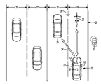
- FIGS. 2 and 3 a schematic depiction of the vehicle 10 using the collision avoidance system 12 is shown.
- FIG. 2 depicts identification of a cyclist 22 within a first lane 24 of a road 26 and an adjacent vehicle 28 within a second lane 30 of the road 26 .
- FIG. 3 depicts the vehicle 10 executing the maneuver from the first lane 24 into the second lane 30 based on the information exchange between the adjacent vehicle 28 and the cyclist 22 .
- the collision avoidance system 12 communicates with the controller 14 and the communication transceiver 16 to obtain and analyze information to safely execute a vehicle maneuver avoiding the cyclist 22 .
- FIG. 2 depicts identification of the cyclist 22 and arbitration between the collision avoidance system 12 , the controller 14 , and the transceiver 16 .
- the transceiver 16 receives data broadcast from the cyclist 22 indicating the cyclist's 22 presence.
- the transceiver 16 uses dedicated short range communication to receive the data from the cyclist 22 . This allows the transceiver 16 to begin receiving input data from the cyclist 22 within a range of approximately 300 m.
- the collision avoidance system 12 may use the vision system 17 , as described above, to confirm the presence of the cyclist 22 .
- the vision system 17 confirms the presence of the cyclist 22 as to vehicle 10 approaches and comes within range of the vision system 17 .
- the transceiver 16 may communicate data received from the cyclist 22 such as the location and speed of the cyclist 22 to the collision avoidance system 12 .
- the vision system 17 also transmits the location of the cyclist 22 to the collision avoidance system 12 .
- Use of both the transceiver 16 and the vision system 17 gives the collision avoidance system 12 an accurate representation of at least the location of the cyclist 22 .
- the navigation system 18 may also provide map data to the collision avoidance system 12 .
- the navigation system 18 may be configured to transmit map data from an external server 32 to instruct the collision avoidance system 12 .
- Map data from the navigation system 18 may include, but is not limited to, an indication of the first lane 24 and the second lane 30 .
- the navigation system 18 instructs the collision avoidance system 12 if the first lane 24 may also be considered a bike lane for the cyclist 22 . Likewise, the navigation system 18 may instruct the collision avoidance system 12 if the first lane 24 may be considered a traveling lane for the vehicle 10 . While the road 26 is depicted as having a first lane 24 and a second lane 30 , the navigation system 18 may also be configured to determine any number of lanes on the road 26 , such as a third lane 31 and a fourth lane 33 .
- the collision avoidance system 12 compares the location data of the cyclist 22 from the transceiver 16 and the vision system 17 and the map data from the navigation system 18 to determine the location of the cyclist 22 within the first lane 24 . While depicted as a cyclist 22 , the transceiver 16 and vision system 17 with the navigation system 18 may be able to instruct the collision avoidance system 12 of any other object's existence that may impede the vehicle 10 . Once the collision avoidance system 12 identifies that the cyclist 22 is traveling in the first lane 24 and impeding the vehicle 10 , the collision avoidance system 12 analyzes the road 26 . For example, using the navigation system 18 and the vision system 17 , the collision avoidance system 12 determines a roadway characteristic 34 , such as lane markings.
- a roadway characteristic 34 such as lane markings.
- the navigation system may instruct the collision avoidance system 12 as to the number of lanes on the road 26 as well as the type of road 26 the vehicle 10 is traveling.
- the vision system 17 may be used to identify and confirm the type of lane markings 34 on the road 26 .
- the navigation system 18 may instruct the collision avoidance system 12 that the vehicle 10 is traveling on a highway and the vision system 17 may identify the dashed yellow lines consistent with the lane markings of a highway.
- the vision system 17 may also be used to identify any other type of lane marking commonly used on the road 26 , such as but not limited to, double yellow lines, single white lines, or a single yellow line with an adjacent dashed yellow line.
- the collision avoidance system 12 uses the roadway characteristics 34 from the navigation system 18 and the vision system 17 to analyze a roadway environment 36 .
- the collision avoidance system 12 may use input from the transceiver 16 to determine and analyze the current roadway environment 36 .
- the transceiver 16 may also be used to transmit data from an adjacent vehicle 28 , or from any other infrastructure that uses dedicated short range communication.
- the roadway environment 36 may include data from traffic lights, stop signs, or any other infrastructure used to affect maneuvers of the vehicle 10 .
- the collision avoidance system 12 uses the roadway characteristics 34 and the roadway environments 36 determined from the transceiver 16 , the vision system 17 , and the navigation system 18 to analyze the environment around and external to the vehicle 10 .
- FIG. 3 continues to depict arbitration between the collision avoidance system 12 , the controller 14 , and the transceiver 16 , as well as depicting maneuver execution of the vehicle 10 .
- the collision avoidance system 12 determines a potential trajectory 38 for the vehicle 10 .
- the potential trajectory 38 may be based on the roadway environment 36 and the roadway characteristics 34 to determine a safe maneuver for the vehicle 10 avoiding the cyclist 22 .
- the potential trajectory 38 may be analyzed by the collision avoidance system 12 and include instances such as crossing into the second lane 30 or biasing the vehicle 10 within the first lane 24 . These determinations are again evaluated based on the roadway characteristics 34 and the roadway environments 36 , as discussed above.
- the collision avoidance system 12 verifies that the potential trajectory 38 will not intersect with the adjacent vehicle 28 or the cyclist 22 . Likewise, the collision avoidance system 12 verifies that the potential trajectory 38 is a legal and safe maneuver for the vehicle 10 . For example, the collision avoidance system 12 verifies that the potential trajectory 38 does not cross double yellow center lane markings or does not pass while crossing an intersection at a stoplight.
- Collision avoidance system 12 may also generate the potential trajectory 38 based on a conditional state 40 of the road 26 .
- the collision avoidance system 12 may receive data from the transceiver 16 indicative of a roadway intrusion 42 , such as a pothole or present construction.
- the collision avoidance system 12 may receive data from the navigation system 18 indicative of a roadway condition 44 , such as a recent rain or ice formation.
- the controller 14 may also receive input from external vehicle sensors 46 to allow the collision avoidance system to verify the roadway condition 44 .
- a rain or temperature sensor and an ultrasonic sensor may allow the controller 14 to instruct the collision avoidance system 12 as to potential road intrusions 42 or roadway conditions 44 .
- the collision avoidance system 12 uses the data indicative of the roadway environment 36 , the roadway characteristics 34 , the roadway intrusions 42 , and the roadway conditions 44 to indicate a probability that the potential trajectory 38 will result in a safe and executable maneuver for the vehicle 10 . If the probability of the potential trajectory 38 is above a preset threshold, the collision avoidance system 12 may begin instructing the controller 14 to execute a maneuver for the vehicle 10 . Likewise, if the probability of the potential trajectory 38 is below the preset threshold, the collision avoidance system 12 aborts the maneuver. This will be discussed in more detail with reference to FIG. 4 .
- the collision avoidance system 12 indicates to an occupant of the pending maneuver.
- the collision avoidance system 12 may instruct the controller 14 to actuate an indicator 48 within a cabin 50 of the vehicle 10 .
- the indicator 48 may be any human machine interface component within the vehicle, such as but not limited to, an auditory warning, a visual warning, or haptic feedback provided to an occupant of the vehicle 10 .
- the indicator 48 may include illuminating lights, producing a tone, or vibrating a vehicle component, such as a steering wheel (not shown), a pedal (not shown), or a seat (not shown).
- the indicator 48 may be active during all instances of execution and may use a single indication, or multiple indications throughout the maneuver execution.
- the controller 14 may actuate the indicator 48 to illuminate a light indicating the presence of the cyclist 22 .
- the controller 14 may then actuate the indicator 48 to produce a tone alerting the occupant that the potential trajectory 38 may either be executed or not executed to avoid the cyclist 22 .
- the controller 14 may also actuate the indicator 48 to provide haptic feedback on the steering wheel to alert the occupant that the vehicle 10 is crossing into the second lane 30 .
- the indicator 48 may also be indicative of execution of the maneuver.
- the light may illuminate in the shape of a bicycle
- the tone may give auditory instructions to the occupant
- the haptic feedback may be present on a side of the steering wheel adjacent to where the potential trajectory 38 may be maneuvering.
- the collision avoidance system 12 maneuvers the vehicle 10 .
- the collision avoidance system 12 maneuvers the vehicle 10 using the controller 14 .
- the controller 14 may actuate vehicle systems, such as but not limited to, the steering system and the brake and accelerator pedal position systems.
- the controller 14 may instruct the steering system and the brake accelerator pedal position systems based upon input received from sensors within the systems. For example, the controller 14 may adjust a steering angle of the steering wheel based on input from a steering angle sensor as compared to the potential trajectory 38 provided by the collision avoidance system 12 .
- the controller 14 may adjust a brake pedal position or an accelerator pedal position based on input from a wheel speed sensor or accelerometer as compared to the potential trajectory 38 provided by the collision avoidance system 12 .
- the controller 14 through use of the steering system and the brake and pedal position systems, may be a lateral positioning controller 14 .
- the lateral positioning controller 14 uses inputs from various vehicle systems, as described above, to safely and accurately maneuver the vehicle 10 around the cyclist 22 according to the potential trajectory 38 as provided by the collision avoidance system 12 .
- the collision avoidance system 12 may constantly monitor the controller 14 , the transceiver 16 , the vision system 17 , and the navigation system 18 .
- the collision avoidance system 12 constantly receives data from the transceiver 16 , the vision system 17 , and the navigation system 18 to allow for compensation during execution of the potential trajectory 38 .
- the adjacent vehicle 28 and/or the cyclist 22 may suddenly and unexpectedly change speed or alter positions. The change in speed or altering of positions of the adjacent vehicle 28 and/or the cyclist 22 may make the potential trajectory 38 unsatisfactory.
- the collision avoidance system 12 may use the transceiver 16 , the vision system 17 , and the navigation system 18 to change or abort the potential trajectory 38 based upon updated input data from the transceiver 16 , the vision system 17 , and the navigation system 18 . Constant monitoring also allows the collision avoidance system 12 to be adaptable based on the roadway environment 36 , the roadway characteristics 34 , the roadway intrusions 42 , and the roadway conditions 44 . The collision avoidance system 12 uses these inputs to abort the potential trajectory 38 if the controller 14 has not yet begun maneuvering, or to generate a second trajectory 52 , if necessary.
- the second trajectory 52 may return the vehicle 10 to the first lane 24 , or may continue to pass the cyclist 22 if the collision avoidance system 12 determines, based on the inputs described above, that passing cyclist 22 is feasible.
- the second trajectory 52 may include returning the vehicle 10 to a center 54 of the first lane 24 and instructing the controller 14 to adjust the speed of the vehicle 10 by changing a brake pedal position.
- the second trajectory 52 may also include a biasing position of the vehicle 10 away from a center 54 of the first lane 24 and crossing into the second lane 30 after the adjacent vehicle 28 has passed.
- the collision avoidance system 12 works in conjunction with the controller 14 , the transceiver 16 , the vision system 17 , and the navigation system 18 to account for and adapt to unexpected events that may occur during normal vehicle operation.
- the collision of avoidance system 12 may instruct the controller 14 to adjust vehicle features to ensure safe passage of the cyclist 22 .
- the collision avoidance system 12 may instruct the controller 14 to lower a windshield wiper speed to avoid wiping excess water from the windshield onto the cyclist 22 .
- the collision avoidance system ensures that the cyclist 22 is not surprised by the passing vehicle 10 and is able to maintain control as the vehicle 10 passes the cyclist 22 .
- the collision avoidance system 12 ensures that the vehicle 10 safely maneuvers around the cyclist 22 .
- FIG. 4 depicts a flow chart of the control logic used by the collision avoidance system 12 .
- the collision avoidance system 12 uses control logic to operate as described above. However, the collision avoidance system 12 may also segment the control logic. For example, the collision avoidance system 12 may also be configured to only generate the warnings as described above, or utilize lane positioning as described above. Likewise, the control logic for the collision avoidance system 12 is described as sequential, however may be operated simultaneously. Operation of the collision avoidance system 12 may be accomplished using the steps described below in any manner or fashion that allows the collision avoidance system 12 to operate as discussed.
- the collision avoidance system 12 constantly monitors inputs from the transceiver, the controller, the navigation system, and the vision system at 60 .
- the collision avoidance system 12 processes these inputs at 62 consistent with the above description.
- Data processing at 62 allows the collision avoidance system 12 to decide if the vehicle is approaching the cyclist at 64 . If at 64 the collision avoidance system 12 determines that the vehicle is not approaching the cyclist, the collision avoidance system returns to continually process the input data at 62 . Continual processing of the input data at 62 allows the collision avoidance system 12 to work continuously to monitor the environment of the vehicle. If at 64 the collision avoidance system 12 determines that the vehicle is approaching the cyclist, the collision avoidance system 12 alerts an occupant of the pending approach at 66 .
- the alert at 66 may be an audible tone at a given frequency or auditory message spoken in a language of the occupant.
- the alert may be a visual indicator, such as illuminating a light, or a physical indicator such as haptic feedback on a seat, steering wheel, or pedal. Alerting the occupant at 66 allows the collision avoidance system 12 to inform the occupant of a possible pending maneuver.
- the collision avoidance system 12 uses the inputs described above to determine if crossing into an adjacent lane is necessary at 68 . If the collision avoidance system 12 determines that crossing into an adjacent lane at 68 is not necessary, the collision avoidance system 12 determines if the current traveling lane of the vehicle is clear of other obstacles at 70 . If at 70 the current traveling lane is not clear of other obstacles, then the collision avoidance system 12 alerts the occupant that executing the maneuver may not be safe at 72 . As stated above, the alert at 72 may be an audible tone at a given frequency or auditory message spoken in a language of the occupant.
- the alert may be a visual indicator, such as illuminating a light, or a physical indicator such as haptic feedback on a seat, steering wheel, or pedal.
- the control logic After the collision avoidance system 12 aborts a potential maneuver at 72 , the control logic returns to again process the input data at 62 . If however the collision avoidance system 12 determines at 70 that the traveling lane is clear of other obstacles, the collision avoidance system 12 may dynamically adjust the position of the vehicle within the current traveling lane at 74 . Dynamically adjusting the position of the vehicle at 74 may include biasing the vehicle to either side of the center of the lane and/or adjusting the speed of the vehicle to account for the cyclist. At 76 , the collision avoidance system 12 instructs the controller to adjust the vehicle systems necessary to account for the cyclist and the control logic continues to process the input data at 62 .
- a visual indicator such as illuminating a light
- a physical indicator such as haptic feedback on a seat, steering wheel, or pedal.
- the collision avoidance system 12 uses the inputs and environment as described above to determine if crossing into the adjacent lane is a legal maneuver at 78 . If at 78 the collision avoidance system 12 determines that crossing into the adjacent lane is not legal, the collision avoidance system 12 alerts the occupant that a maneuver will not be attempted for legal reasons at 80 and the control logic continues to process the input data at 62 . Alerting the occupant at 80 that the maneuver will not be attempted due to legal reasons, allows the occupant an opportunity to verify the accuracy of the determination made by the collision avoidance system 12 at 78 .
- the alert at 80 may be an audible tone at a given frequency or auditory message spoken in a language of the occupant.
- the alert may be a visual indicator, such as illuminating a light, or a physical indicator such as haptic feedback on a seat, steering wheel, or pedal.
- the collision avoidance system 12 determines if crossing into the adjacent lane is a legal maneuver. Again, the collision avoidance system 12 makes a determination that execution of a possible maneuver is safe at 82 based on inputs received from the vehicle systems indicative of the surrounding vehicle environment, the roadway characteristics, possible roadway of obtrusion, and the roadway condition. If the collision avoidance system 12 determines that crossing into the adjacent lane is not safe at 82 , the collision avoidance system 12 instructs the controller to alert the occupant that a maneuver will not be attempted due to safety considerations at 84 and the control logic continues to process the input data at 62 .
- Alerting the occupant that a maneuver may not be executed due to safety considerations at 84 allows the occupant to verify the accuracy of the determination made by the collision avoidance system 12 at 82 . This allows the occupant to override the determination at 82 and eliminates potential error of the collision avoidance system 12 .
- the alert at 84 may be an audible tone at a given frequency or auditory message spoken in a language of the occupant.
- the alert may be a visual indicator, such as illuminating a light, or a physical indicator such as haptic feedback on a seat, steering wheel, or pedal.
- the collision avoidance system 12 determines that a maneuver may be attempted, the collision avoidance system alerts the occupant that the vehicle will execute the maneuver based on the calculated trajectory at 86 .
- the alert at 86 may be an audible tone at a given frequency or auditory message spoken in a language of the occupant.
- the alert may be a visual indicator, such as illuminating a light, or a physical indicator such as haptic feedback on a seat, steering wheel, or pedal. Alerting the occupant that a vehicle maneuver will be attempted at 86 allows the occupant an opportunity to abort the maneuver.
- the collision avoidance system 12 will monitor preset vehicle system inputs indicative of an occupant-initiated abortion of the maneuver and determine at 88 if the occupant has signaled to abort the maneuver.
- the preset vehicle system inputs indicative of an occupant-initiated abortion may include, but are not limited to, depressing the brake pedal, a voice recognition feature for the occupant, or using a human machine interface to select a button on a display.
- the collision avoidance system 12 receives input of an occupant-initiated abortion, the maneuver will not be executed and the control logic continues to process the input data at 62 . However, if at 88 the collision avoidance system 12 does not receive input of an occupant-initiated abortion, then at 90 the collision avoidance system 12 will instruct the controller to use lateral position control and partially move into the adjacent lane, or move completely into the adjacent lane avoiding the cyclist. The collision avoidance system 12 will automatically steer the vehicle to avoid the collision on a path that is based on map data from the navigation system identifying a marking type for the traveling lane.
- These attributes may include, but are not limited to cost, strength, durability, life cycle cost, marketability, appearance, packaging, size, serviceability, weight, manufacturability, ease of assembly, etc. As such, embodiments described as less desirable than other embodiments or prior art implementations with respect to one or more characteristics are not outside the scope of the disclosure and may be desirable for particular applications.
Landscapes
- Engineering & Computer Science (AREA)
- Transportation (AREA)
- Mechanical Engineering (AREA)
- Automation & Control Theory (AREA)
- Chemical & Material Sciences (AREA)
- Combustion & Propulsion (AREA)
- Physics & Mathematics (AREA)
- General Physics & Mathematics (AREA)
- Traffic Control Systems (AREA)
- Control Of Driving Devices And Active Controlling Of Vehicle (AREA)
- Steering Control In Accordance With Driving Conditions (AREA)
Abstract
A vehicle includes a steering wheel and a controller. The controller is configured to, in response to receiving location and speed data from other vehicles indicating an expected collision absent a trajectory change, automatically control the steering wheel to direct the vehicle along a collision avoidance path. The collision avoidance path is based on map data identifying a marking type for a traveling lane such that the path crosses the lane when the marking type is broken and does not cross the lane when the marking type is solid.
Description
- The present disclosure relates to collision avoidance systems for vehicles.
- Vehicles may use dedicated short range communication to exchange information with other vehicles, roadway infrastructure, or other objects traveling on the roadway such as cyclists. The collision avoidance system for a vehicle may use this information to avoid obstacles, determine roadway conditions, or find alternate routes through traffic. Collision avoidance systems may also communicate information exchanged using dedicated short range communication to other vehicle control systems to aid in efficiently operating the vehicle.
- A system includes a controller. The controller is configured to, in response to receiving location and speed data from other vehicles indicating an expected collision absent a trajectory change, steer a vehicle to avoid the collision on a path. The path is based on map data identifying a marking type for a traveling lane such that the path crosses the lane when the marking type is broken and does not cross the lane when the marking type is solid.
- A vehicle includes a steering wheel and a controller. The controller is configured to, in response to receiving location and speed data from other vehicles indicating an expected collision absent a trajectory change, automatically control the steering wheel to direct the vehicle along a collision avoidance path. The collision avoidance path is based on map data identifying a marking type for a traveling lane such that the path crosses the lane when the marking type is broken and does not cross the lane when the marking type is solid.
- A control method for a vehicle includes, in response to receiving data from other vehicles indicating an expected collision absent a trajectory change, automatically steering the vehicle to avoid the collision on a path. The path is based on data identifying a marking type for a traveling lane such that the path crosses the lane when the marking type is broken and does not cross the lane when the marking type is solid.
-
FIG. 1 is a diagrammatic view of a vehicle having a collision avoidance system; -
FIG. 2 is a diagrammatic view of a vehicle detecting an object using a DSRC transceiver; -
FIG. 3 is a diagrammatic view of a vehicle generating a trajectory to pass the object; and -
FIG. 4 is a flowchart depicting the control logic of the collision avoidance system. - Embodiments of the present disclosure are described herein. It is to be understood, however, that the disclosed embodiments are merely examples and other embodiments may take various and alternative forms. The figures are not necessarily to scale; some features could be exaggerated or minimized to show details of particular components. Therefore, specific structural and functional details disclosed herein are not to be interpreted as limiting, but merely as a representative basis for teaching one skilled in the art to variously employ the present invention. As those of ordinary skill in the art will understand, various features illustrated and described with reference to any one of the figures may be combined with features illustrated in one or more other figures to produce embodiments that are not explicitly illustrated or described. The combinations of features illustrated provide representative embodiments for typical applications. Various combinations and modifications of the features consistent with the teachings of this disclosure, however, could be desired for particular applications or implementations.
-
FIG. 1 depicts avehicle 10 having acollision avoidance system 12. Thecollision avoidance system 12 may instruct acontroller 14 in communication with acommunication transceiver 16. Thecommunication transceiver 16 may be configured to send and receive information indicative of the location of thevehicle 10, the speed of thevehicle 10, and a potential trajectory of thevehicle 10. In at least one embodiment, thetransceiver 16 may be a dedicated short range communication transceiver. Thecommunication transceiver 16 may also use information exchange networks such as, but not limited to, Bluetooth, Wi-Fi, or any other vehicle information exchange communication system. The dedicated shortrange communication transceiver 16 may allow for communication from vehicle-to-vehicle (V2V), or from vehicle-to-everything (V2X) including roadway infrastructure, cyclists, or any other object that utilizes acommunication transceiver 16. - As will be described with more detail below, objects such as cyclists may produce unique obstacles for occupants on a roadway. Having a
collision avoidance system 12 able to communicate information received from acommunication transceiver 16 with avehicle controller 14 allows for improved communication between vehicles that share the roadway and objects on the roadway. Improved communication between vehicles and objects on the roadway further aids in preventing impact events. For example, as will be described with reference to the other figures, a cyclist (not shown) may occupy a vehicle lane (not shown). Thecollision avoidance system 12 may use anavigation system 18 as well as avision system 17 to exchange information, via thecommunication transceiver 16, with the cyclist. Thevision system 17 may use onboard cameras, ultrasonic sensors, or any other sensor that may detect vehicle surroundings. Thevision system 17 may use the cameras and the ultrasonic sensors either individually or simultaneously to accurately depict the surroundings of the vehicle. Thenavigation system 18 may use map data and global positioning system data to transfer information such as vehicle speed, vehicle trajectory, and the roadway environment. - The
collision avoidance system 12 uses the information transfer from thecommunication transceiver 16 and thevision system 17 andnavigation system 18 to improve performance of thevehicle 10. Thecollision avoidance system 12 communicates the information to thecontroller 14 in order to alert an occupant of an oncoming object, such as a cyclist, adjust the vehicle trajectory to compensate for the cyclist, or alter vehicle components, such as a brake pedal position, to adjust a vehicle position relative to the cyclist. Thecollision avoidance system 12 may instruct thecontroller 14 to adjust other vehicle systems either individually, or simultaneously as the circumstances require. Thecontroller 14 may be configured to adjust any vehicle system, such as asteering system 20 that may aid in improving performance of thevehicle 10 based on the information received from thecommunication transceiver 16 of the cyclist's position, speed, or trajectory. - Referring to
FIGS. 2 and 3 , a schematic depiction of thevehicle 10 using thecollision avoidance system 12 is shown.FIG. 2 depicts identification of acyclist 22 within afirst lane 24 of aroad 26 and anadjacent vehicle 28 within asecond lane 30 of theroad 26.FIG. 3 depicts thevehicle 10 executing the maneuver from thefirst lane 24 into thesecond lane 30 based on the information exchange between theadjacent vehicle 28 and thecyclist 22. As will be discussed in more detail below, thecollision avoidance system 12 communicates with thecontroller 14 and thecommunication transceiver 16 to obtain and analyze information to safely execute a vehicle maneuver avoiding thecyclist 22. -
FIG. 2 depicts identification of thecyclist 22 and arbitration between thecollision avoidance system 12, thecontroller 14, and thetransceiver 16. As thevehicle 10 approaches thecyclist 22, thetransceiver 16 receives data broadcast from thecyclist 22 indicating the cyclist's 22 presence. In at least one embodiment, thetransceiver 16 uses dedicated short range communication to receive the data from thecyclist 22. This allows thetransceiver 16 to begin receiving input data from thecyclist 22 within a range of approximately 300 m. Once acyclist 22 has been identified by thetransceiver 16, thecollision avoidance system 12 may use thevision system 17, as described above, to confirm the presence of thecyclist 22. Thevision system 17 confirms the presence of thecyclist 22 as tovehicle 10 approaches and comes within range of thevision system 17. - The
transceiver 16 may communicate data received from thecyclist 22 such as the location and speed of thecyclist 22 to thecollision avoidance system 12. Thevision system 17 also transmits the location of thecyclist 22 to thecollision avoidance system 12. Use of both thetransceiver 16 and thevision system 17 gives thecollision avoidance system 12 an accurate representation of at least the location of thecyclist 22. Thenavigation system 18 may also provide map data to thecollision avoidance system 12. For example, thenavigation system 18 may be configured to transmit map data from anexternal server 32 to instruct thecollision avoidance system 12. Map data from thenavigation system 18 may include, but is not limited to, an indication of thefirst lane 24 and thesecond lane 30. Thenavigation system 18 instructs thecollision avoidance system 12 if thefirst lane 24 may also be considered a bike lane for thecyclist 22. Likewise, thenavigation system 18 may instruct thecollision avoidance system 12 if thefirst lane 24 may be considered a traveling lane for thevehicle 10. While theroad 26 is depicted as having afirst lane 24 and asecond lane 30, thenavigation system 18 may also be configured to determine any number of lanes on theroad 26, such as athird lane 31 and afourth lane 33. - The
collision avoidance system 12 compares the location data of thecyclist 22 from thetransceiver 16 and thevision system 17 and the map data from thenavigation system 18 to determine the location of thecyclist 22 within thefirst lane 24. While depicted as acyclist 22, thetransceiver 16 andvision system 17 with thenavigation system 18 may be able to instruct thecollision avoidance system 12 of any other object's existence that may impede thevehicle 10. Once thecollision avoidance system 12 identifies that thecyclist 22 is traveling in thefirst lane 24 and impeding thevehicle 10, thecollision avoidance system 12 analyzes theroad 26. For example, using thenavigation system 18 and thevision system 17, thecollision avoidance system 12 determines a roadway characteristic 34, such as lane markings. - As stated above, the navigation system may instruct the
collision avoidance system 12 as to the number of lanes on theroad 26 as well as the type ofroad 26 thevehicle 10 is traveling. Thevision system 17 may be used to identify and confirm the type oflane markings 34 on theroad 26. For example, thenavigation system 18 may instruct thecollision avoidance system 12 that thevehicle 10 is traveling on a highway and thevision system 17 may identify the dashed yellow lines consistent with the lane markings of a highway. Thevision system 17 may also be used to identify any other type of lane marking commonly used on theroad 26, such as but not limited to, double yellow lines, single white lines, or a single yellow line with an adjacent dashed yellow line. - The
collision avoidance system 12 uses theroadway characteristics 34 from thenavigation system 18 and thevision system 17 to analyze aroadway environment 36. Thecollision avoidance system 12 may use input from thetransceiver 16 to determine and analyze thecurrent roadway environment 36. Thetransceiver 16, as stated above, may also be used to transmit data from anadjacent vehicle 28, or from any other infrastructure that uses dedicated short range communication. For example, theroadway environment 36 may include data from traffic lights, stop signs, or any other infrastructure used to affect maneuvers of thevehicle 10. Thecollision avoidance system 12 uses theroadway characteristics 34 and theroadway environments 36 determined from thetransceiver 16, thevision system 17, and thenavigation system 18 to analyze the environment around and external to thevehicle 10. -
FIG. 3 continues to depict arbitration between thecollision avoidance system 12, thecontroller 14, and thetransceiver 16, as well as depicting maneuver execution of thevehicle 10. After analyzing the environment external to thevehicle 10, thecollision avoidance system 12 determines a potential trajectory 38 for thevehicle 10. The potential trajectory 38 may be based on theroadway environment 36 and theroadway characteristics 34 to determine a safe maneuver for thevehicle 10 avoiding thecyclist 22. The potential trajectory 38 may be analyzed by thecollision avoidance system 12 and include instances such as crossing into thesecond lane 30 or biasing thevehicle 10 within thefirst lane 24. These determinations are again evaluated based on theroadway characteristics 34 and theroadway environments 36, as discussed above. For example, thecollision avoidance system 12 verifies that the potential trajectory 38 will not intersect with theadjacent vehicle 28 or thecyclist 22. Likewise, thecollision avoidance system 12 verifies that the potential trajectory 38 is a legal and safe maneuver for thevehicle 10. For example, thecollision avoidance system 12 verifies that the potential trajectory 38 does not cross double yellow center lane markings or does not pass while crossing an intersection at a stoplight. -
Collision avoidance system 12 may also generate the potential trajectory 38 based on aconditional state 40 of theroad 26. For example, thecollision avoidance system 12 may receive data from thetransceiver 16 indicative of aroadway intrusion 42, such as a pothole or present construction. Likewise, thecollision avoidance system 12 may receive data from thenavigation system 18 indicative of aroadway condition 44, such as a recent rain or ice formation. Thecontroller 14 may also receive input from external vehicle sensors 46 to allow the collision avoidance system to verify theroadway condition 44. For example, a rain or temperature sensor and an ultrasonic sensor may allow thecontroller 14 to instruct thecollision avoidance system 12 as topotential road intrusions 42 orroadway conditions 44. Thecollision avoidance system 12 uses the data indicative of theroadway environment 36, theroadway characteristics 34, the roadway intrusions 42, and theroadway conditions 44 to indicate a probability that the potential trajectory 38 will result in a safe and executable maneuver for thevehicle 10. If the probability of the potential trajectory 38 is above a preset threshold, thecollision avoidance system 12 may begin instructing thecontroller 14 to execute a maneuver for thevehicle 10. Likewise, if the probability of the potential trajectory 38 is below the preset threshold, thecollision avoidance system 12 aborts the maneuver. This will be discussed in more detail with reference toFIG. 4 . - If maneuvering the
vehicle 10 is probable, thecollision avoidance system 12 indicates to an occupant of the pending maneuver. Thecollision avoidance system 12 may instruct thecontroller 14 to actuate anindicator 48 within a cabin 50 of thevehicle 10. Theindicator 48 may be any human machine interface component within the vehicle, such as but not limited to, an auditory warning, a visual warning, or haptic feedback provided to an occupant of thevehicle 10. For example, theindicator 48 may include illuminating lights, producing a tone, or vibrating a vehicle component, such as a steering wheel (not shown), a pedal (not shown), or a seat (not shown). Theindicator 48 may be active during all instances of execution and may use a single indication, or multiple indications throughout the maneuver execution. For example, thecontroller 14 may actuate theindicator 48 to illuminate a light indicating the presence of thecyclist 22. - The
controller 14 may then actuate theindicator 48 to produce a tone alerting the occupant that the potential trajectory 38 may either be executed or not executed to avoid thecyclist 22. Thecontroller 14 may also actuate theindicator 48 to provide haptic feedback on the steering wheel to alert the occupant that thevehicle 10 is crossing into thesecond lane 30. Theindicator 48 may also be indicative of execution of the maneuver. As by examples, the light may illuminate in the shape of a bicycle, the tone may give auditory instructions to the occupant, and the haptic feedback may be present on a side of the steering wheel adjacent to where the potential trajectory 38 may be maneuvering. By actuating theindicator 48 through all stages of execution, thecollision avoidance system 12 also allows an occupant to abort the potential trajectory 38. - If the probability of the potential trajectory 38 is above the threshold and an occupant has not aborted the potential trajectory 38 based on the
indicator 48, thecollision avoidance system 12 maneuvers thevehicle 10. Thecollision avoidance system 12 maneuvers thevehicle 10 using thecontroller 14. Thecontroller 14 may actuate vehicle systems, such as but not limited to, the steering system and the brake and accelerator pedal position systems. Thecontroller 14 may instruct the steering system and the brake accelerator pedal position systems based upon input received from sensors within the systems. For example, thecontroller 14 may adjust a steering angle of the steering wheel based on input from a steering angle sensor as compared to the potential trajectory 38 provided by thecollision avoidance system 12. Likewise, thecontroller 14 may adjust a brake pedal position or an accelerator pedal position based on input from a wheel speed sensor or accelerometer as compared to the potential trajectory 38 provided by thecollision avoidance system 12. Thecontroller 14, through use of the steering system and the brake and pedal position systems, may be alateral positioning controller 14. Thelateral positioning controller 14 uses inputs from various vehicle systems, as described above, to safely and accurately maneuver thevehicle 10 around thecyclist 22 according to the potential trajectory 38 as provided by thecollision avoidance system 12. - The
collision avoidance system 12 may constantly monitor thecontroller 14, thetransceiver 16, thevision system 17, and thenavigation system 18. Thecollision avoidance system 12 constantly receives data from thetransceiver 16, thevision system 17, and thenavigation system 18 to allow for compensation during execution of the potential trajectory 38. For example, theadjacent vehicle 28 and/or thecyclist 22 may suddenly and unexpectedly change speed or alter positions. The change in speed or altering of positions of theadjacent vehicle 28 and/or thecyclist 22 may make the potential trajectory 38 unsatisfactory. By constantly monitoring, thecollision avoidance system 12 may use thetransceiver 16, thevision system 17, and thenavigation system 18 to change or abort the potential trajectory 38 based upon updated input data from thetransceiver 16, thevision system 17, and thenavigation system 18. Constant monitoring also allows thecollision avoidance system 12 to be adaptable based on theroadway environment 36, theroadway characteristics 34, the roadway intrusions 42, and the roadway conditions 44. Thecollision avoidance system 12 uses these inputs to abort the potential trajectory 38 if thecontroller 14 has not yet begun maneuvering, or to generate a second trajectory 52, if necessary. - The second trajectory 52 may return the
vehicle 10 to thefirst lane 24, or may continue to pass thecyclist 22 if thecollision avoidance system 12 determines, based on the inputs described above, that passingcyclist 22 is feasible. For example, the second trajectory 52 may include returning thevehicle 10 to acenter 54 of thefirst lane 24 and instructing thecontroller 14 to adjust the speed of thevehicle 10 by changing a brake pedal position. The second trajectory 52 may also include a biasing position of thevehicle 10 away from acenter 54 of thefirst lane 24 and crossing into thesecond lane 30 after theadjacent vehicle 28 has passed. Thecollision avoidance system 12 works in conjunction with thecontroller 14, thetransceiver 16, thevision system 17, and thenavigation system 18 to account for and adapt to unexpected events that may occur during normal vehicle operation. - Further, while passing the
cyclist 22, the collision ofavoidance system 12 may instruct thecontroller 14 to adjust vehicle features to ensure safe passage of thecyclist 22. For example, thecollision avoidance system 12 may instruct thecontroller 14 to lower a windshield wiper speed to avoid wiping excess water from the windshield onto thecyclist 22. By instructing thecontroller 14 to adjust various vehicle features, the collision avoidance system ensures that thecyclist 22 is not surprised by the passingvehicle 10 and is able to maintain control as thevehicle 10 passes thecyclist 22. Thecollision avoidance system 12 ensures that thevehicle 10 safely maneuvers around thecyclist 22. -
FIG. 4 depicts a flow chart of the control logic used by thecollision avoidance system 12. Thecollision avoidance system 12 uses control logic to operate as described above. However, thecollision avoidance system 12 may also segment the control logic. For example, thecollision avoidance system 12 may also be configured to only generate the warnings as described above, or utilize lane positioning as described above. Likewise, the control logic for thecollision avoidance system 12 is described as sequential, however may be operated simultaneously. Operation of thecollision avoidance system 12 may be accomplished using the steps described below in any manner or fashion that allows thecollision avoidance system 12 to operate as discussed. - As described above, the
collision avoidance system 12 constantly monitors inputs from the transceiver, the controller, the navigation system, and the vision system at 60. Thecollision avoidance system 12 processes these inputs at 62 consistent with the above description. Data processing at 62 allows thecollision avoidance system 12 to decide if the vehicle is approaching the cyclist at 64. If at 64 thecollision avoidance system 12 determines that the vehicle is not approaching the cyclist, the collision avoidance system returns to continually process the input data at 62. Continual processing of the input data at 62 allows thecollision avoidance system 12 to work continuously to monitor the environment of the vehicle. If at 64 thecollision avoidance system 12 determines that the vehicle is approaching the cyclist, thecollision avoidance system 12 alerts an occupant of the pending approach at 66. As stated above, the alert at 66 may be an audible tone at a given frequency or auditory message spoken in a language of the occupant. In at least one other embodiment, the alert may be a visual indicator, such as illuminating a light, or a physical indicator such as haptic feedback on a seat, steering wheel, or pedal. Alerting the occupant at 66 allows thecollision avoidance system 12 to inform the occupant of a possible pending maneuver. - The
collision avoidance system 12 uses the inputs described above to determine if crossing into an adjacent lane is necessary at 68. If thecollision avoidance system 12 determines that crossing into an adjacent lane at 68 is not necessary, thecollision avoidance system 12 determines if the current traveling lane of the vehicle is clear of other obstacles at 70. If at 70 the current traveling lane is not clear of other obstacles, then thecollision avoidance system 12 alerts the occupant that executing the maneuver may not be safe at 72. As stated above, the alert at 72 may be an audible tone at a given frequency or auditory message spoken in a language of the occupant. In at least one other embodiment, the alert may be a visual indicator, such as illuminating a light, or a physical indicator such as haptic feedback on a seat, steering wheel, or pedal. After thecollision avoidance system 12 aborts a potential maneuver at 72, the control logic returns to again process the input data at 62. If however thecollision avoidance system 12 determines at 70 that the traveling lane is clear of other obstacles, thecollision avoidance system 12 may dynamically adjust the position of the vehicle within the current traveling lane at 74. Dynamically adjusting the position of the vehicle at 74 may include biasing the vehicle to either side of the center of the lane and/or adjusting the speed of the vehicle to account for the cyclist. At 76, thecollision avoidance system 12 instructs the controller to adjust the vehicle systems necessary to account for the cyclist and the control logic continues to process the input data at 62. - Referring back to 68, if the
collision avoidance system 12 determines that crossing into the adjacent lane is necessary, thecollision avoidance system 12 uses the inputs and environment as described above to determine if crossing into the adjacent lane is a legal maneuver at 78. If at 78 thecollision avoidance system 12 determines that crossing into the adjacent lane is not legal, thecollision avoidance system 12 alerts the occupant that a maneuver will not be attempted for legal reasons at 80 and the control logic continues to process the input data at 62. Alerting the occupant at 80 that the maneuver will not be attempted due to legal reasons, allows the occupant an opportunity to verify the accuracy of the determination made by thecollision avoidance system 12 at 78. As stated above, the alert at 80 may be an audible tone at a given frequency or auditory message spoken in a language of the occupant. In at least one other embodiment, the alert may be a visual indicator, such as illuminating a light, or a physical indicator such as haptic feedback on a seat, steering wheel, or pedal. - If at 78 the
collision avoidance system 12 determines that crossing into the adjacent lane is a legal maneuver, the collision avoidance system then determines if crossing into the adjacent lane constitutes a safe maneuver at 82. Again, thecollision avoidance system 12 makes a determination that execution of a possible maneuver is safe at 82 based on inputs received from the vehicle systems indicative of the surrounding vehicle environment, the roadway characteristics, possible roadway of obtrusion, and the roadway condition. If thecollision avoidance system 12 determines that crossing into the adjacent lane is not safe at 82, thecollision avoidance system 12 instructs the controller to alert the occupant that a maneuver will not be attempted due to safety considerations at 84 and the control logic continues to process the input data at 62. Alerting the occupant that a maneuver may not be executed due to safety considerations at 84 allows the occupant to verify the accuracy of the determination made by thecollision avoidance system 12 at 82. This allows the occupant to override the determination at 82 and eliminates potential error of thecollision avoidance system 12. As stated above, the alert at 84 may be an audible tone at a given frequency or auditory message spoken in a language of the occupant. In at least one other embodiment, the alert may be a visual indicator, such as illuminating a light, or a physical indicator such as haptic feedback on a seat, steering wheel, or pedal. - If at 82 the
collision avoidance system 12 determines that a maneuver may be attempted, the collision avoidance system alerts the occupant that the vehicle will execute the maneuver based on the calculated trajectory at 86. As stated above, the alert at 86 may be an audible tone at a given frequency or auditory message spoken in a language of the occupant. In at least one other embodiment, the alert may be a visual indicator, such as illuminating a light, or a physical indicator such as haptic feedback on a seat, steering wheel, or pedal. Alerting the occupant that a vehicle maneuver will be attempted at 86 allows the occupant an opportunity to abort the maneuver. Thecollision avoidance system 12 will monitor preset vehicle system inputs indicative of an occupant-initiated abortion of the maneuver and determine at 88 if the occupant has signaled to abort the maneuver. The preset vehicle system inputs indicative of an occupant-initiated abortion may include, but are not limited to, depressing the brake pedal, a voice recognition feature for the occupant, or using a human machine interface to select a button on a display. - If at 88 the
collision avoidance system 12 receives input of an occupant-initiated abortion, the maneuver will not be executed and the control logic continues to process the input data at 62. However, if at 88 thecollision avoidance system 12 does not receive input of an occupant-initiated abortion, then at 90 thecollision avoidance system 12 will instruct the controller to use lateral position control and partially move into the adjacent lane, or move completely into the adjacent lane avoiding the cyclist. Thecollision avoidance system 12 will automatically steer the vehicle to avoid the collision on a path that is based on map data from the navigation system identifying a marking type for the traveling lane. - While exemplary embodiments are described above, it is not intended that these embodiments describe all possible forms encompassed by the claims. The words used in the specification are words of description rather than limitation, and it is understood that various changes may be made without departing from the spirit and scope of the disclosure. As previously described, the features of various embodiments may be combined to form further embodiments of the invention that may not be explicitly described or illustrated. While various embodiments could have been described as providing advantages or being preferred over other embodiments or prior art implementations with respect to one or more desired characteristics, those of ordinary skill in the art recognize that one or more features or characteristics may be compromised to achieve desired overall system attributes, which depend on the specific application and implementation. These attributes may include, but are not limited to cost, strength, durability, life cycle cost, marketability, appearance, packaging, size, serviceability, weight, manufacturability, ease of assembly, etc. As such, embodiments described as less desirable than other embodiments or prior art implementations with respect to one or more characteristics are not outside the scope of the disclosure and may be desirable for particular applications.
Claims (15)
1. A system comprising:
a controller configured to, in response to receiving location and speed data from other vehicles indicating an expected collision absent a trajectory change, steer a vehicle to avoid the collision on a path that is based on map data identifying a marking type for a traveling lane such that the path crosses the lane when the marking type is broken and does not cross the lane when the marking type is solid.
2. The system of claim 1 , wherein the controller is further configured to generate an alert of the automatic steering.
3. The system of claim 2 , wherein the alert is haptic feedback that is provided on an area of a steering wheel in a direction of the path.
4. The system of claim 2 , wherein the alert is an audible tone having a constant frequency.
5. The system of claim 2 , wherein the alert is a visual status indicator light within the vehicle.
6. A vehicle comprising:
a steering wheel; and
a controller configured to, in response to receiving location and speed data from other vehicles indicating an expected collision absent a trajectory change, automatically control the steering wheel to direct the vehicle along a collision avoidance path that is based on map data identifying a marking type for a traveling lane such that the path crosses the lane when the marking type is broken and does not cross the lane when the marking type is solid.
7. The vehicle of claim 6 further comprising a dedicated short range communication transceiver configured to receive the location and speed data.
8. The vehicle of claim 6 , wherein the controller is further configured to, in response receiving stop light status data, adjust the collision avoidance path to account for the stop light status data.
9. The vehicle of claim 6 , wherein the controller is further configured to, in response to the marking type being solid, brake the vehicle.
10. A control method for a vehicle comprising:
in response to receiving data from other vehicles indicating an expected collision absent a trajectory change, automatically steering the vehicle to avoid the collision on a path that is based on data identifying a marking type for a traveling lane such that the path crosses the lane when the marking type is broken and does not cross the lane when the marking type is solid.
11. The control method of claim 10 , wherein the path crosses the lane when the marking type is broken into an adjacent lane.
12. The control method of claim 10 , wherein the path is such that a position of the vehicle is biased within the traveling lane to avoid the expected collision.
13. The control method of claim 10 , wherein the path is such that a speed of the vehicle is adjusted to account for an object within the traveling lane.
14. The control method of claim 10 further comprising receiving additional data from the other vehicles and automatically steering the vehicle onto another path.
15. The control method of claim 10 further comprising, in response to receiving data indicating an occupant-initiated abort request, cancel the automatically steering.
Priority Applications (6)
| Application Number | Priority Date | Filing Date | Title |
|---|---|---|---|
| US14/945,513 US9771071B2 (en) | 2015-11-19 | 2015-11-19 | Dynamic lane positioning for improved biker safety |
| DE102016121873.1A DE102016121873A1 (en) | 2015-11-19 | 2016-11-15 | Dynamic lane positioning for improved cyclist safety |
| GB1619469.8A GB2546373B (en) | 2015-11-19 | 2016-11-17 | Dynamic lane positioning for improved biker safety |
| CN201611019822.XA CN106846906A (en) | 2015-11-19 | 2016-11-17 | Dynamic lane location for improving bicyclist's security |
| MX2016015103A MX357153B (en) | 2015-11-19 | 2016-11-17 | Dynamic lane positioning for improved biker safety. |
| RU2016145231A RU2731586C2 (en) | 2015-11-19 | 2016-11-18 | Vehicle control system and method for avoiding collisions and vehicle |
Applications Claiming Priority (1)
| Application Number | Priority Date | Filing Date | Title |
|---|---|---|---|
| US14/945,513 US9771071B2 (en) | 2015-11-19 | 2015-11-19 | Dynamic lane positioning for improved biker safety |
Publications (2)
| Publication Number | Publication Date |
|---|---|
| US20170144657A1 true US20170144657A1 (en) | 2017-05-25 |
| US9771071B2 US9771071B2 (en) | 2017-09-26 |
Family
ID=57993820
Family Applications (1)
| Application Number | Title | Priority Date | Filing Date |
|---|---|---|---|
| US14/945,513 Active 2036-03-24 US9771071B2 (en) | 2015-11-19 | 2015-11-19 | Dynamic lane positioning for improved biker safety |
Country Status (6)
| Country | Link |
|---|---|
| US (1) | US9771071B2 (en) |
| CN (1) | CN106846906A (en) |
| DE (1) | DE102016121873A1 (en) |
| GB (1) | GB2546373B (en) |
| MX (1) | MX357153B (en) |
| RU (1) | RU2731586C2 (en) |
Cited By (6)
| Publication number | Priority date | Publication date | Assignee | Title |
|---|---|---|---|---|
| US10037700B2 (en) * | 2015-11-09 | 2018-07-31 | Denso Corporation | Driving support apparatus for a vehicle |
| KR20190109629A (en) * | 2018-02-28 | 2019-09-26 | 삼성전자주식회사 | Autonomous driving device and driving method thereof |
| US20210101620A1 (en) * | 2020-12-17 | 2021-04-08 | Intel Corporation | Systems, methods, and devices for generating and using safety threat maps |
| US20210241622A1 (en) * | 2018-04-19 | 2021-08-05 | Micron Technology, Inc. | Systems and methods for automatically warning nearby vehicles of potential hazards |
| US11427190B2 (en) * | 2016-02-29 | 2022-08-30 | Huawei Technologies Co., Ltd. | Self-driving method, and apparatus |
| US11940798B2 (en) * | 2018-07-06 | 2024-03-26 | Toyota Research Institute, Inc. | System, method, and computer-readable medium for an autonomous vehicle to pass a bicycle |
Families Citing this family (5)
| Publication number | Priority date | Publication date | Assignee | Title |
|---|---|---|---|---|
| WO2012068331A1 (en) * | 2010-11-19 | 2012-05-24 | Magna Electronics Inc. | Lane keeping system and lane centering system |
| JP6622148B2 (en) * | 2016-06-17 | 2019-12-18 | 日立オートモティブシステムズ株式会社 | Ambient environment recognition device |
| DE102017209533A1 (en) * | 2017-06-07 | 2018-12-13 | Bayerische Motoren Werke Aktiengesellschaft | Lane change assistance system and lane change assistance method with increased safety for the driver and other road users |
| DE102017212373A1 (en) | 2017-07-19 | 2019-01-24 | Volkswagen Aktiengesellschaft | Method for determining a trajectory for an autonomously driving motor vehicle, control device and motor vehicle |
| US10703340B2 (en) | 2018-02-02 | 2020-07-07 | Ford Global Technologies, Llc | Sensor cleaning system |
Citations (3)
| Publication number | Priority date | Publication date | Assignee | Title |
|---|---|---|---|---|
| US8838372B2 (en) * | 2011-05-02 | 2014-09-16 | Denso Corporation | Collision probability calculation apparatus for vehicle |
| US9245448B2 (en) * | 2001-07-31 | 2016-01-26 | Magna Electronics Inc. | Driver assistance system for a vehicle |
| US9273971B2 (en) * | 2013-05-28 | 2016-03-01 | Hyundai Motor Company | Apparatus and method for detecting traffic lane using wireless communication |
Family Cites Families (20)
| Publication number | Priority date | Publication date | Assignee | Title |
|---|---|---|---|---|
| US7546182B2 (en) * | 2006-02-21 | 2009-06-09 | Gm Global Technology Operations, Inc. | Inter vehicular ad hoc routing protocol and communication system |
| KR101075615B1 (en) * | 2006-07-06 | 2011-10-21 | 포항공과대학교 산학협력단 | Apparatus and method for generating a auxiliary information of moving vehicles for driver |
| JP4861850B2 (en) * | 2007-02-13 | 2012-01-25 | アイシン・エィ・ダブリュ株式会社 | Lane determination device and lane determination method |
| JP4970156B2 (en) | 2007-06-12 | 2012-07-04 | 富士重工業株式会社 | Vehicle driving support device |
| JP2008282326A (en) | 2007-05-14 | 2008-11-20 | Mitsubishi Electric Corp | Two-wheeler collision prevention system |
| DE102008005999A1 (en) | 2008-01-25 | 2009-07-30 | Daimler Ag | A driver assistance system and method for assisting the driver of a vehicle while maintaining a lane limited by lane markings |
| CN101813492B (en) * | 2010-04-19 | 2012-11-14 | 清华大学 | Vehicle navigation system and method |
| WO2011137477A1 (en) | 2010-05-04 | 2011-11-10 | Cameron Harrison | Cyclist proximity warning system |
| US8620549B2 (en) * | 2010-09-14 | 2013-12-31 | GM Global Technology Operations LLC | Vehicle safety systems and methods |
| WO2012080799A1 (en) | 2010-12-13 | 2012-06-21 | Ikubu Cc | Collision early warning system and method |
| RU2526144C2 (en) * | 2012-06-25 | 2014-08-20 | Федеральное государственное бюджетное образовательное учреждение высшего профессионального образования "Московский государственный индустриальный университет" | Method for prevention of vehicle collision with dynamic obstacle |
| US9048960B2 (en) | 2012-08-17 | 2015-06-02 | Qualcomm Incorporated | Methods and apparatus for communicating safety message information |
| CN102785661B (en) | 2012-08-20 | 2015-05-13 | 深圳先进技术研究院 | Lane departure control system and lane departure control method |
| US8473144B1 (en) | 2012-10-30 | 2013-06-25 | Google Inc. | Controlling vehicle lateral lane positioning |
| DE202013006469U1 (en) * | 2013-07-18 | 2014-10-22 | GM Global Technology Operations LLC (n. d. Gesetzen des Staates Delaware) | Control unit of a motor vehicle |
| DE102013217434A1 (en) * | 2013-09-02 | 2015-03-05 | Bayerische Motoren Werke Aktiengesellschaft | overtaking |
| US9090260B2 (en) | 2013-12-04 | 2015-07-28 | Mobileye Vision Technologies Ltd. | Image-based velocity control for a turning vehicle |
| CN104751677B (en) * | 2013-12-27 | 2017-07-18 | 上海博泰悦臻网络技术服务有限公司 | vehicle collision alarm method and system |
| CN103921788B (en) * | 2014-04-02 | 2018-03-16 | 奇瑞汽车股份有限公司 | A kind of running car control system and method |
| CN104299453A (en) * | 2014-11-11 | 2015-01-21 | 东莞市钜大电子有限公司 | Safety driving system of vehicle |
-
2015
- 2015-11-19 US US14/945,513 patent/US9771071B2/en active Active
-
2016
- 2016-11-15 DE DE102016121873.1A patent/DE102016121873A1/en active Granted
- 2016-11-17 CN CN201611019822.XA patent/CN106846906A/en active Pending
- 2016-11-17 MX MX2016015103A patent/MX357153B/en active IP Right Grant
- 2016-11-17 GB GB1619469.8A patent/GB2546373B/en active Active
- 2016-11-18 RU RU2016145231A patent/RU2731586C2/en active
Patent Citations (3)
| Publication number | Priority date | Publication date | Assignee | Title |
|---|---|---|---|---|
| US9245448B2 (en) * | 2001-07-31 | 2016-01-26 | Magna Electronics Inc. | Driver assistance system for a vehicle |
| US8838372B2 (en) * | 2011-05-02 | 2014-09-16 | Denso Corporation | Collision probability calculation apparatus for vehicle |
| US9273971B2 (en) * | 2013-05-28 | 2016-03-01 | Hyundai Motor Company | Apparatus and method for detecting traffic lane using wireless communication |
Cited By (11)
| Publication number | Priority date | Publication date | Assignee | Title |
|---|---|---|---|---|
| US10037700B2 (en) * | 2015-11-09 | 2018-07-31 | Denso Corporation | Driving support apparatus for a vehicle |
| US10297156B2 (en) * | 2015-11-09 | 2019-05-21 | Denso Corporation | Driving support apparatus for a vehicle |
| US11427190B2 (en) * | 2016-02-29 | 2022-08-30 | Huawei Technologies Co., Ltd. | Self-driving method, and apparatus |
| KR20190109629A (en) * | 2018-02-28 | 2019-09-26 | 삼성전자주식회사 | Autonomous driving device and driving method thereof |
| US11325590B2 (en) * | 2018-02-28 | 2022-05-10 | Samsung Electronics Co., Ltd. | Autonomous driving device and driving method thereof |
| KR102532741B1 (en) * | 2018-02-28 | 2023-05-16 | 삼성전자주식회사 | Autonomous driving device and driving method thereof |
| US20210241622A1 (en) * | 2018-04-19 | 2021-08-05 | Micron Technology, Inc. | Systems and methods for automatically warning nearby vehicles of potential hazards |
| US11705004B2 (en) * | 2018-04-19 | 2023-07-18 | Micron Technology, Inc. | Systems and methods for automatically warning nearby vehicles of potential hazards |
| US20230351893A1 (en) * | 2018-04-19 | 2023-11-02 | Lodestar Licensing Group Llc | Systems and methods for automatically warning nearby vehicles of potential hazards |
| US11940798B2 (en) * | 2018-07-06 | 2024-03-26 | Toyota Research Institute, Inc. | System, method, and computer-readable medium for an autonomous vehicle to pass a bicycle |
| US20210101620A1 (en) * | 2020-12-17 | 2021-04-08 | Intel Corporation | Systems, methods, and devices for generating and using safety threat maps |
Also Published As
| Publication number | Publication date |
|---|---|
| DE102016121873A1 (en) | 2017-05-24 |
| RU2016145231A3 (en) | 2020-04-06 |
| RU2016145231A (en) | 2018-05-21 |
| MX2016015103A (en) | 2017-07-04 |
| US9771071B2 (en) | 2017-09-26 |
| GB2546373B (en) | 2021-05-12 |
| CN106846906A (en) | 2017-06-13 |
| RU2731586C2 (en) | 2020-09-04 |
| GB201619469D0 (en) | 2017-01-04 |
| GB2546373A (en) | 2017-07-19 |
| MX357153B (en) | 2018-06-27 |
Similar Documents
| Publication | Publication Date | Title |
|---|---|---|
| US9771071B2 (en) | Dynamic lane positioning for improved biker safety | |
| US10864911B2 (en) | Automated detection of hazardous drifting vehicles by vehicle sensors | |
| US9594373B2 (en) | Apparatus and method for continuously establishing a boundary for autonomous driving availability and an automotive vehicle comprising such an apparatus | |
| JP5614055B2 (en) | Driving assistance device | |
| US9324233B2 (en) | Vehicle contact warning method and system | |
| WO2018101253A1 (en) | Vehicle control device | |
| WO2018159429A1 (en) | Driving assistance method, and driving assistance device and driving assistance system using said method | |
| JP6485792B2 (en) | Driving support control device | |
| JP4983564B2 (en) | Vehicle tracking device | |
| JP2018100009A (en) | Vehicle control device | |
| CN111132883A (en) | Vehicle control device | |
| WO2013153660A1 (en) | Driving assistance device | |
| US20180151074A1 (en) | Collision avoidance support device provided with braking release means and collision avoidance support method | |
| WO2018101254A1 (en) | Vehicle control device | |
| JP2005161977A (en) | Vehicular travel supporting device | |
| US11433882B2 (en) | Method and device for performing an at least partially automated driving maneuver | |
| JP6376523B2 (en) | Vehicle control device | |
| JP2019003235A (en) | Target information acquisition device | |
| JP2009070254A (en) | Vehicle risk estimation device | |
| JP6376522B2 (en) | Vehicle control device | |
| WO2018168330A1 (en) | Driving assist control device | |
| GB2616356A (en) | Communicating vehicle information to pedestrians | |
| JP6662351B2 (en) | Vehicle control device | |
| JP2012212271A (en) | Driving support device | |
| JP2005145282A (en) | Vehicle running supporting device |
Legal Events
| Date | Code | Title | Description |
|---|---|---|---|
| AS | Assignment |
Owner name: FORD GLOBAL TECHNOLOGIES, LLC, MICHIGAN Free format text: ASSIGNMENT OF ASSIGNORS INTEREST;ASSIGNORS:HASSANI, ALI;HOELLERBAUER, JAKOB NIKOLAUS;DUTTA, ARUN;AND OTHERS;SIGNING DATES FROM 20151106 TO 20151117;REEL/FRAME:037084/0625 |
|
| STCF | Information on status: patent grant |
Free format text: PATENTED CASE |
|
| MAFP | Maintenance fee payment |
Free format text: PAYMENT OF MAINTENANCE FEE, 4TH YEAR, LARGE ENTITY (ORIGINAL EVENT CODE: M1551); ENTITY STATUS OF PATENT OWNER: LARGE ENTITY Year of fee payment: 4 |