US201626A - Improvement in machines for stamping letters - Google Patents
Improvement in machines for stamping letters Download PDFInfo
- Publication number
- US201626A US201626A US201626DA US201626A US 201626 A US201626 A US 201626A US 201626D A US201626D A US 201626DA US 201626 A US201626 A US 201626A
- Authority
- US
- United States
- Prior art keywords
- machines
- improvement
- letters
- carriage
- rod
- Prior art date
- Legal status (The legal status is an assumption and is not a legal conclusion. Google has not performed a legal analysis and makes no representation as to the accuracy of the status listed.)
- Expired - Lifetime
Links
- 230000033001 locomotion Effects 0.000 description 3
- 230000000994 depressogenic effect Effects 0.000 description 2
- 241000306729 Ligur Species 0.000 description 1
- 238000010276 construction Methods 0.000 description 1
- 230000008878 coupling Effects 0.000 description 1
- 238000010168 coupling process Methods 0.000 description 1
- 238000005859 coupling reaction Methods 0.000 description 1
Images
Classifications
-
- C—CHEMISTRY; METALLURGY
- C14—SKINS; HIDES; PELTS; LEATHER
- C14B—MECHANICAL TREATMENT OR PROCESSING OF SKINS, HIDES OR LEATHER IN GENERAL; PELT-SHEARING MACHINES; INTESTINE-SPLITTING MACHINES
- C14B1/00—Manufacture of leather; Machines or devices therefor
- C14B1/44—Mechanical treatment of leather surfaces
- C14B1/56—Ornamenting, producing designs, embossing
Definitions
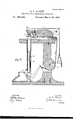
- Figure l of the drawings is a representation of a perspective view of my stampingmachine.
- Fig. 2 is a longitudinal vertical section.
- This invention has relation to improvements in machines for stamping letters.
- the object of the invention is to devise a stamp-canceler of such a nature that the operator may be seated and work the apparatus with his feet, thus leaving his hands free to handle the postal matter, and that the inkrwill be fed automatically to the canceling-die.
- the letter A designates an ordinary table-top, supported upon the legs a a', one or more of which may be metallic.
- rIhe leg a is tubular, and receives a preferably metallic rod, b, having upon its upper end a metallic platform, b', that is flush with the table-top when the said rod is lowered to its full extent into the tubular leg a.
- the rod b is, preferably, cylindrical, and is prevented from rotating by means of a guidepin, c, extending through the wall of the leg a, and engaging a longitudinal groove in the said rod.
- the lower end of the rod b rests upon a vertically-vibratory bell-cranklever, B, extending through the leg a, and having its fulcrum thereon in spaced offsets.
- the power end of this lever is connected by a coupling to a treadle, C, and, when depressed, raises the rod b and thrusts its platform up against a can ⁇ celing-die, D, rigidly secured to an overhanging metallic arm, E, upon the table, effectually canceling a stamp placed upon the said platform.
- the arm E has at each end, near its upper edge, two spaced rollers, d d', and it carries an inking-carriage, F, which has free endwise horizontal motion upon its horizontal arm.
- This carriage has at its front lower edge two projecting vertically-vibratory arms, e, that are supported each by a spring, f, and ai'ord bearings in their free ends for an inking-roller, g.
- G represents a flexible cord, of any suitable material, rigidly secured to the weight end of the bell-crank lever, extending thence under a large pulley, H, in the leg a upward to and over a pulley, h, on arm E, whence it is carried to the front, and attached to the carriage.
- I represents other cords, one of which is attached to each side of the carriage, near its front upper edge, whence they extend to the front over the pulleys d thence to the rear over the pulleys d', and, being carried downward, are attached to a weight, W.
- the roller In the passage of the carriage to the rear, the roller passes over a transverse drip-slit, opening into an ink-receptacle in the arm E, and is supplied with ink, which, at the forward movement of the said carriage, is applied to the face of the canceling-die.
Landscapes
- Engineering & Computer Science (AREA)
- Manufacturing & Machinery (AREA)
- Mechanical Engineering (AREA)
- Chemical & Material Sciences (AREA)
- Organic Chemistry (AREA)
- Accessory Devices And Overall Control Thereof (AREA)
Description
' 2 sheets-sheet 1.
A. C. PAQUET. Machine for Stamping Letters.
No. 201,626. Patened March 26.187?.
.mm r-IIIIIHIH` #fiar/z @y N, PETERS, PHDTO-UTHOGRAFHER WASHINGTON, D C4 UNITED STATES PATENT OFFICE.
ANTHONY CQPAQHET, oF PHILADELPHIA, PENNSYLVANIA.
IMPROVEMENT IN MACHINES FOR STAMPING LETTERS.
Specification forming part of Letters Patent No. 201,626, dated March 26, 1878 application filed Y February 2, 1878.
To all whomit't may concern:
Be it known that I, ANTHONY C. PAQUET, of Philadelphia, in the county of Philadelphia and State of Pennsylvania, have invented a new and valuable Improvement in Machines for Stamping Letters; and I do hereby declare that' the following is a full, clear, and
- exact description of the construction and operation of the same, reference being had to the annexed drawings, making a part of this specification, and to the letters and ligures of reference marked thereon.
Figure l of the drawings is a representation of a perspective view of my stampingmachine. Fig. 2 is a longitudinal vertical section.
This invention has relation to improvements in machines for stamping letters.
The object of the invention is to devise a stamp-canceler of such a nature that the operator may be seated and work the apparatus with his feet, thus leaving his hands free to handle the postal matter, and that the inkrwill be fed automatically to the canceling-die.
The nature of the invention consists in certain novel combinations of parts, as will be hereinafter more fully explained.
In the annexed drawings, the letter A designates an ordinary table-top, supported upon the legs a a', one or more of which may be metallic.
rIhe leg a is tubular, and receives a preferably metallic rod, b, having upon its upper end a metallic platform, b', that is flush with the table-top when the said rod is lowered to its full extent into the tubular leg a.
The rod b is, preferably, cylindrical, and is prevented from rotating by means of a guidepin, c, extending through the wall of the leg a, and engaging a longitudinal groove in the said rod.
The lower end of the rod b rests upon a vertically-vibratory bell-cranklever, B, extending through the leg a, and having its fulcrum thereon in spaced offsets. The power end of this lever is connected by a coupling to a treadle, C, and, when depressed, raises the rod b and thrusts its platform up against a can` celing-die, D, rigidly secured to an overhanging metallic arm, E, upon the table, effectually canceling a stamp placed upon the said platform.
The arm E has at each end, near its upper edge, two spaced rollers, d d', and it carries an inking-carriage, F, which has free endwise horizontal motion upon its horizontal arm. This carriage has at its front lower edge two projecting vertically-vibratory arms, e, that are supported each by a spring, f, and ai'ord bearings in their free ends for an inking-roller, g.
G represents a flexible cord, of any suitable material, rigidly secured to the weight end of the bell-crank lever, extending thence under a large pulley, H, in the leg a upward to and over a pulley, h, on arm E, whence it is carried to the front, and attached to the carriage.
I represents other cords, one of which is attached to each side of the carriage, near its front upper edge, whence they extend to the front over the pulleys d thence to the rear over the pulleys d', and, being carried downward, are attached to a weight, W.
When the angular lever is depressed, th carriage is drawn to the rear by the cord G, and at the same time the weight W is raised by the cords I. The rod b is raised, as aforesaid, at the same time and thrust against the canceling-die.
When the lever B is released, the weight W draws the carriage to the front, carrying the inkingroller over the face of the die, and supplying it with the canceling medium, vibrating the Vangular lever B, and lowering the plunger-rod until its platform is flush with the table, all these motions being simultaneous. i
In the passage of the carriage to the rear, the roller passes over a transverse drip-slit, opening into an ink-receptacle in the arm E, and is supplied with ink, which, at the forward movement of the said carriage, is applied to the face of the canceling-die.
What I claim as new, and desire to secure by Letters Patent, is
The combination, with a stationary stamperate substantially as specified.
In testimony that I claim the above I have hereunto subscribed my name in the presence of two Witnesses. y
ANTHONY C. PAQUET. Witnesses:
ALLEN H. GANGEWER, DE LANGY G. WALKER.
Publications (1)
| Publication Number | Publication Date |
|---|---|
| US201626A true US201626A (en) | 1878-03-26 |
Family
ID=2271031
Family Applications (1)
| Application Number | Title | Priority Date | Filing Date |
|---|---|---|---|
| US201626D Expired - Lifetime US201626A (en) | Improvement in machines for stamping letters |
Country Status (1)
| Country | Link |
|---|---|
| US (1) | US201626A (en) |
-
0
- US US201626D patent/US201626A/en not_active Expired - Lifetime
Similar Documents
| Publication | Publication Date | Title |
|---|---|---|
| US374496A (en) | Exercising-machine | |
| US201626A (en) | Improvement in machines for stamping letters | |
| US144743A (en) | Improvement in ironing-machines | |
| US589123A (en) | Morocco-glassing machine | |
| US107714A (en) | Improvement in ironing-machines | |
| US69261A (en) | Henry f | |
| US312643A (en) | Leather-cutting machine | |
| US55738A (en) | Improvement in sawi ng-mach ines | |
| USRE6654E (en) | Improvement in ironing apparatus | |
| US160141A (en) | Improvement in fly-brush attachments | |
| US129251A (en) | Improvement in leather scouring machines | |
| US175202A (en) | Improvement in medical rubbing apparatus | |
| US322217A (en) | Tailor s pressing-machine | |
| US450178A (en) | Saw-smithing machine | |
| US478431A (en) | Mortising-machine | |
| US653915A (en) | Machine for branding hams, &c. | |
| US233755A (en) | Eapids | |
| US445589A (en) | S h eet- metal- fold i ng machine | |
| US424759A (en) | Perforating-machine | |
| US527827A (en) | Machine for black-leading electrotype-matrices | |
| US309432A (en) | Metal-punching machine | |
| US275305A (en) | Albeet whiting | |
| US1180629A (en) | Numbering-machine. | |
| US940688A (en) | Fan attachment for chairs. | |
| US239277A (en) | smith |