US2016151A - Phantoscope - Google Patents
Phantoscope Download PDFInfo
- Publication number
- US2016151A US2016151A US741194A US74119434A US2016151A US 2016151 A US2016151 A US 2016151A US 741194 A US741194 A US 741194A US 74119434 A US74119434 A US 74119434A US 2016151 A US2016151 A US 2016151A
- Authority
- US
- United States
- Prior art keywords
- cabinet
- translucent window
- source
- examination
- illumination
- Prior art date
- Legal status (The legal status is an assumption and is not a legal conclusion. Google has not performed a legal analysis and makes no representation as to the accuracy of the status listed.)
- Expired - Lifetime
Links
- 210000003484 anatomy Anatomy 0.000 description 23
- 210000000056 organ Anatomy 0.000 description 21
- 238000005286 illumination Methods 0.000 description 16
- 210000004072 lung Anatomy 0.000 description 6
- 210000002216 heart Anatomy 0.000 description 5
- 238000005266 casting Methods 0.000 description 4
- 239000002131 composite material Substances 0.000 description 3
- 230000008602 contraction Effects 0.000 description 3
- 230000003534 oscillatory effect Effects 0.000 description 3
- 210000002784 stomach Anatomy 0.000 description 3
- 239000011521 glass Substances 0.000 description 2
- 239000000123 paper Substances 0.000 description 2
- 238000005381 potential energy Methods 0.000 description 2
- 229920000742 Cotton Polymers 0.000 description 1
- 101100001674 Emericella variicolor andI gene Proteins 0.000 description 1
- 230000004075 alteration Effects 0.000 description 1
- 210000000988 bone and bone Anatomy 0.000 description 1
- 238000010438 heat treatment Methods 0.000 description 1
- 239000000463 material Substances 0.000 description 1
- 239000002184 metal Substances 0.000 description 1
- 230000004048 modification Effects 0.000 description 1
- 238000012986 modification Methods 0.000 description 1
- 210000003205 muscle Anatomy 0.000 description 1
- NJPPVKZQTLUDBO-UHFFFAOYSA-N novaluron Chemical compound C1=C(Cl)C(OC(F)(F)C(OC(F)(F)F)F)=CC=C1NC(=O)NC(=O)C1=C(F)C=CC=C1F NJPPVKZQTLUDBO-UHFFFAOYSA-N 0.000 description 1
- 230000010355 oscillation Effects 0.000 description 1
- 230000002093 peripheral effect Effects 0.000 description 1
- 229920000136 polysorbate Polymers 0.000 description 1
- 230000002035 prolonged effect Effects 0.000 description 1
- 238000009877 rendering Methods 0.000 description 1
- 230000029058 respiratory gaseous exchange Effects 0.000 description 1
- 210000001519 tissue Anatomy 0.000 description 1
- 210000003462 vein Anatomy 0.000 description 1
- 230000000007 visual effect Effects 0.000 description 1
Images

Classifications
-
- G—PHYSICS
- G09—EDUCATION; CRYPTOGRAPHY; DISPLAY; ADVERTISING; SEALS
- G09B—EDUCATIONAL OR DEMONSTRATION APPLIANCES; APPLIANCES FOR TEACHING, OR COMMUNICATING WITH, THE BLIND, DEAF OR MUTE; MODELS; PLANETARIA; GLOBES; MAPS; DIAGRAMS
- G09B23/00—Models for scientific, medical, or mathematical purposes, e.g. full-sized devices for demonstration purposes
- G09B23/28—Models for scientific, medical, or mathematical purposes, e.g. full-sized devices for demonstration purposes for medicine
- G09B23/286—Models for scientific, medical, or mathematical purposes, e.g. full-sized devices for demonstration purposes for medicine for scanning or photography techniques, e.g. X-rays, ultrasonics
Definitions
- My invention relates to X-ray devices and more particularly to a device for accurately portraying the human anatomy and movements of various organs thereof, such as the heart, lungs, stomach,
- Another object of my present invention is the 30. provision of a device for educational purposes vwherein certain parts of the human anatomy and the normal functionof variousiorgans thereof-.
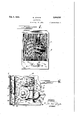
- Figure l is a front elevational view of my. viewing device depictinga portion o the human anatomy andshowing the shape and motion of various organs.
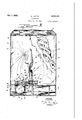
- Figure 2 is a side elevational view -of my device partly in section and having parts thereof broken away to better illustrate the mechanism.
- Fig-3 isan elevational view partly in section taken on ⁇ the line III- Ill of Fig. 2 with a portion of the device broken away for illustrative purposes.
- g Fig. 4 is a fragmentary plan view of a portion of my device taken on the lin'e IV-IV in Fig. 2.
- a source of illumination such as an incandescent lamp 8 is positioned interiorly ofthe cabinet,
- a reiiector I0 is positioned rearwardly of the lamp and the .interior oi the cabinet is provided with a reflecting surface so that all direct and indirect light 10 is projected toward the transparent window 6.
- a pair of channel members I2 and I3 are disposed transversely of' the cabinet 5 immediately in back of the translucent window and are rigidly supported by suitable means such as pedestal 15 brackets I4.
- a composite plate I5 slidably enl gages the channel members I2 and 'I3 and snthus disposed between the source of illumination and the translucent window 6 so that thelight rays impinge thereupon.l
- I utilize a piece of translucent paper'or thincardboard
- This sheet is disposed between two sheets of glass I1 to hold itflrmly in a-position 30 simulating the posture of a patient and distributed at random over the, front side of the cardboard or sheetI place ⁇ a material, such as ne cotton or thelike I8, lwhich portrays the small veins and other minute tissues normally ob- 35 served. Should it be'preferred in some instances f I may utilize an actual X-ray negative iilm in lieu of the translucent paper. or thin-cardboard.
- I provide the interior of the cabinet-with mechanism operable to cause a shadow to be observed from the front of the cabinet which is movable inthe same manner as the actual organsofthe body observed during a iluorosco'pic examination.
- f u f This -mechanism may compr-isean electric motor I9. energizable froma suitable source oi electrical energy, .in the same manner asthe lamp 8, upon closure of a switch 20 which may also be disposed inthe front of the cabinet.
- a rotatable member 22 is connected throughreduction gear- ⁇ ing 23 to the shaft of ⁇ the electric motor I9 and the lower peripheral edge ofthis member is provided with a cam surface 24.
- a stud 25 extends 55 and establishing contact with the remaining camV lupwardly from the bottom of the cabinet which is provided with an elongated slot 26.
- a collar 21 slidably engages this stud 25, being prevented from rotation thereabout by a set screw 28 engaging the slot 26, and a biasing spring 29 is interposed between the base of the cabinet and this collar for the purpose of maintaining a roller 30, carried by the collar 21, lin engagement with the cam surface 24.
- a short shaft 32 is rigidly secured to and forms a part of the collar 21, which extends toward the front of the cabinet and secured to the end of this shaft is a plate 33 disposed in back of the translucent window 6. This plate extends transversely of the cabinet 5, being slidably held in place by means of loose fitting channels 34 to permit reciprocatory movement, and is so constructed as to simulate the contraction and expansion of certain muscles caused by breathing of a patient as observed during a fluoroscopic examination.
- the rotatable member 22 is further provided with a pair of cam surfaces 35 and 36 which may be in the'form of plates or the like rigidly secured to this member as by means of a pin 31.
- An elongated bracket 38 is supported by the base 0f the cabinet and extends upwardly therefrom being' provided with laterally extending portions 39 and 40 forming bearings.
- a pair of concentric Shafts 42 and 43 are journaled Within the lower bearing 46 andthe inner shaft 43 extends through the bearing 39 with the upper end thereof having secured thereto a metallic member 44 of a configuration adapted to cast a shadow simulating that of the human heart.
- the upper portion of the outer shaft 42 is journaled upon the inner shaft 43 and at its upper end has rigidly secured thereto a bifurcated member 45 with each branch thereof in turn provided with a metallic member 46 and 41, ⁇ respectively, which upon illumination of the lamp 6, causes a shadow to be superimposed upon the translucent window 6 depicting thecon.- figuration of the human' lungs as observed during a iiuoroscopic examination.
- the metallic members 44, 46 and V41 are caused to oscillate by the rotary movement of the member 22.
- the lower end of the shaft 42 is provided with a rocker arm 48 rigidly secured thereto ⁇ which is provided with a roller contacting the cam surface 35.
- 'a ⁇ rocker arm 50 is rigidly secured to the lower end of the shaft 43 having a roller 52 secured thereto surface 36.
- the bracket or upright 38 is provided with a further lateral'extension ⁇ 53 rigidly secured thereto and a pair of coil springs 64 and 55 are yconnected to this'extension and to the rocker arms bythese rocker arms in firm contact with the -46 and 50,.respectively, for the purpose of normally maintaining 4the rollers 49 and 52 carried respective cam surfaces 36.and 36.
- the member 221s accordingly rotated by the electric motor I9 the surfaces 3lii'andI 36 are thus rotated causing a rocking motion yof both the rocker arms cured to the respective shafts 42 andl 43 will cause o reciprocating rotary motion thereof with attendant oscillation of the metallic members 44, 46v and 41.
- the composite plate l5 which depicts the various organs, hereinbefore referred to, thus fiuctuates in size giving an accurate visual indication from the front of the cabinet and upon the translucent window 6 of a contraction and expansion of these organs as actually observed during a fiuoroscopic examination.
- a disengagingmechanism comprising a substantially L.shaped rod or shaft 56 adapted to be moved into engagement with both rocker arms 48 and 46, at the opposite side of their respective pivot points to that of the rollers 4920 and 52, thus causing contact of the latter with thereto.
- This lever is in turn pivotally connected by a link or the like 63 to the shaft 56 so that movement of the lever 62 about its pivot causes a sliding movement of this shaft with engagement and disengagement of the angularly disposed por- 36, tion thereof with the rocker arms 48 and 56.
- the rod or shaft 56 engages these lrocker armsv they are rotated, as above noted, to interrupt contact of the rollers with the cam surfaces and upon disengagement of the shaft 56 the rollers carried by the rocker arms are again forced. in to contact with the cam surfaces by the potential energy of the coil springs 54 and 66.
- An educational device for medical students that depicts an image of the human anatomy 66 and the natural motion of various organs thereof as viewed upon a fluorescent screen by the utili-- zation of X-rays comprising a cabinet provided with a translucent window, a source of illumination in said cabinet for projecting light rays to- 78 ward said translucent window, means disposed between said source of illumination and said window for portraying upon said window a shadow simulating certain parts 'of the human anatomy as actually observed during a uorcopie exam- 1G
- the shadow cast by these members upon 5 inaton, and means in said cabinet for superimposing a shadow upon said translucent window to the natural motion of various organs thereof as y viewed upon a fluorescent screen by the utilization of X-rays comprising a cabinet provided with a translucent window, a source of illumination in said cabinet for projecting light rays .toward said translucent window, means disposed be-v tween said source of illumination and said window for portraying upon said window a shadow simulating certain parts
- An educational'device for medical students that depicts an image of the human anatomy and the natural motion of various organs thereof as viewed upon a fluorescent screen by the utilizat-l tion of X-rays comprising a cabinet provided with- 'a translucent window, a source of illumination disposed in said cabinet for-projecting light rays toward said translucent window, means disposed in said cabinet between said source of illumination and said translucent window for absorbing a portion of the light rays from said source and casting a shadow upon saidtranslucent window simulating certain parts of the human anatomy as observed during a fiuoroscopic examination, means disposed between said source of illumination and said rst mentioned means for casting a shadow upon said translucent window having ⁇ a conguration depicting certain organs of the human anatomy, and means connected to said last mentioned means and operable to cause oscillatory movement thereof whereby the shadow cast is caused to fluctuate and portray the natural motion ofcertain organs of kthe human anatomy to an observer in front of said cabinet in the same manner as would a living person during a fiu
- An educational device for medical students that depicts an image of the human anatomy and the natural motion of various organs thereof as viewed upon a iluorescent screen by the utilization of X-rayscomprising a cabinet provided with a translucent window, a source of illumination disposed in said cabinet for projecting light rays toward said translucent window, means disposed in said cabinet between said source of illumination and said translucent window for absorbing a simulating certain parts of the human anatomy as observed during a uoroscopic examination, and mechanism disposed in said cabinet and operable to cast asuperimposed movable shadow upon the shadow cast by said last mentioned means to depict the natural motion of various 5 organs of the anatomy whereby an observer in front of said cabinet obtains an accurate portrayal of certain parts of the human anatomy as actually seen upon a fluorescent screen during a uoroscopic examination. 10
- An educational device for medical students that depicts an image of the human anatomy and the natural motion of various organs thereof as viewed upon a uorescent screen by the utilization of X-rays comprising Aa cabinet provided l5 with a translucent window, a source of illumina.- tion disposed in said cabinet for projecting light rays toward saidtranslucentwindow, a composite plate disposed in said cabinet between said source of illumination and said translucent window for l alter in configuration and accurately simulate the natural motion of the various organs portrayed as observed during a fluoroscopic examination of a living human being.
- An educational device for medical students that depicts an image of the human anatomy and the natural motion of various organs thereof as viewed upon a iiuorescent screen by the utilizat- 4o tion of X-rays comprising a cabinet provided with av translucent window, a source of illumination disposed in said cabinet for projecting light rays toward said translucentwindow, means disposed in said cabinet between said source of illumination and said translucent window for absorbing a portion of the light rays from said source and casting a shadow upon said translucent window conforming to certain parts'of the human, anatomy as observed during a fluoroscopic examina- 5 0 tion, and mechanism disposed in said ⁇ cabinetv comprising a plurality of members interposed between said translucent window and said source of illumination having a configuration causing a shadow to be superimposed upon said translucent 65 window depicting various organs of the human anatomy, an electricmotor, a rotatable member connected to said motor for operation thereby and provided with a plurality of cam surfaces, and connections from said rotatable member to said 60 pluralit
Landscapes
- Engineering & Computer Science (AREA)
- General Physics & Mathematics (AREA)
- Health & Medical Sciences (AREA)
- Physics & Mathematics (AREA)
- Computational Mathematics (AREA)
- Mathematical Optimization (AREA)
- Medical Informatics (AREA)
- Medicinal Chemistry (AREA)
- Chemical & Material Sciences (AREA)
- Algebra (AREA)
- Radiology & Medical Imaging (AREA)
- Nuclear Medicine, Radiotherapy & Molecular Imaging (AREA)
- Mathematical Analysis (AREA)
- General Health & Medical Sciences (AREA)
- Mathematical Physics (AREA)
- Pure & Applied Mathematics (AREA)
- Business, Economics & Management (AREA)
- Educational Administration (AREA)
- Educational Technology (AREA)
- Theoretical Computer Science (AREA)
- Apparatus For Radiation Diagnosis (AREA)
Description
Oct. l, 1935,
- ummullilllll I'Il Mass: d'
PHANTosco1-=E Filed Aug.. 24, 1934 LEVNE 2,016,151
y 3i Sheets-Sheet l ATTORNEY v G. LEVENE PHANToscoPE Oct. 1, 1935.
3y sheets-sheet 5 Filed Aug. 24, 1954 n fr |NvENToR 6. EVE/VE.
[BY/77 @A ATTORNEY Patented OchA 1, 1935 PBANTOSQOPE i George Levene, Norwood, Mass., assignor to West'- l inghouse X-Ray Company, Inc., Long Island City, N. Y., a corporation of Delaware Application August 24,
6 Claims.
My invention relates to X-ray devices and more particularly to a device for accurately portraying the human anatomy and movements of various organs thereof, such as the heart, lungs, stomach,
etc., as actually-seen during a iluoroscopic examination thus rendering the device highly desirable from an educational standpoint.
In the making of fluoroscopic examinations it is necessary that they not only be made in a dark quired for radiographic exposures. Moreover; if the fluoroscopic examination is of very long duration such as in instances where it is desired to study the actionof various moving parts of the body as the heart-and lungs, it frequently b'ecome's necessary to intermittently energize the X-ray tube to prevent undue heating thereof. 5This accordingly renders it somewhat difficult to utilize a subject to portray the action of' various parts of the body as viewed uoroscopically for educational and similar purposes. l It is accordingly an object of my present invention to provide a. device for depicting certain parts ofthe human anatomy and the motion of various organs thereof, as viewed during a fluoroscopic examination,-in order that their action may beaccurately studied during several cycles. Another object of my present invention-is the 30. provision of a device for educational purposes vwherein certain parts of the human anatomy and the normal functionof variousiorgans thereof-.
may be accurately portrayed as actually observed during a-fluoroscopic examination without the necessity of subjecting. 'a patientv to-X-rays for prolonged periods of time.
Still further objects of my present inventionl wlll'become obvious' tothose skilledin the art to which it. appertains by reference to the accom- 40 panying drawings wherein:
Figure l is a front elevational view of my. viewing device depictinga portion o the human anatomy andshowing the shape and motion of various organs.
45 Figure 2 is a side elevational view -of my device partly in section and having parts thereof broken away to better illustrate the mechanism.
Fig-3 isan elevational view partly in section taken on`the line III- Ill of Fig. 2 with a portion of the device broken away for illustrative purposes. if g Fig. 4 is a fragmentary plan view of a portion of my device taken on the lin'e IV-IV in Fig. 2.
Referring now to the drawings in detail I have room, but also that the X-ray tube be' energized' for considerably longer periods of time than re'- shown in the several iigures a cabinet 5 of sheet l 1934, Serial No. 741,194
metal or the like having a translucent window 6 of glass and a closure member, such as a door 1. A source of illumination, such as an incandescent lamp 8 is positioned interiorly ofthe cabinet,
which is energizable from a suitable source lof 5 electrical energy upon closure of a switch 9 disposed in the front of the cabinet.. A reiiector I0 is positioned rearwardly of the lamp and the .interior oi the cabinet is provided with a reflecting surface so that all direct and indirect light 10 is projected toward the transparent window 6.
A pair of channel members I2 and I3 are disposed transversely of' the cabinet 5 immediately in back of the translucent window and are rigidly supported by suitable means such as pedestal 15 brackets I4. A composite plate I5 slidably enl gages the channel members I2 and 'I3 and snthus disposed between the source of illumination and the translucent window 6 so that thelight rays impinge thereupon.l In order to make this plate 20 depict certain parts of the anatomy of a human being, as actually observed upon a fluorescent screen during a iiuoroscopic examination, I utilize a piece of translucent paper'or thincardboard,
such as shown at I6, and cut away portions there- 25 of but leaving portions to simulate .the bones and other Vthick parts .of the human4 anatomy, which 'absorb the X-rays during the usual iiuoroscopic examination.` This sheet is disposed between two sheets of glass I1 to hold itflrmly in a-position 30 simulating the posture of a patient and distributed at random over the, front side of the cardboard or sheetI place` a material, such as ne cotton or thelike I8, lwhich portrays the small veins and other minute tissues normally ob- 35 served. Should it be'preferred in some instances f I may utilize an actual X-ray negative iilm in lieu of the translucent paper. or thin-cardboard.
vFor the purpose of illustrating Vthe normal motion of various organs of the body, such asthe 40 heart, lungs, and stomach, I provide the interior of the cabinet-with mechanism operable to cause a shadow to be observed from the front of the cabinet which is movable inthe same manner as the actual organsofthe body observed during a iluorosco'pic examination. f u f This -mechanism may compr-isean electric motor I9. energizable froma suitable source oi electrical energy, .in the same manner asthe lamp 8, upon closure of a switch 20 which may also be disposed inthe front of the cabinet. A rotatable member 22 is connected throughreduction gear- `ing 23 to the shaft of` the electric motor I9 and the lower peripheral edge ofthis member is provided with a cam surface 24. .A stud 25 extends 55 and establishing contact with the remaining camV lupwardly from the bottom of the cabinet which is provided with an elongated slot 26.
A collar 21 slidably engages this stud 25, being prevented from rotation thereabout by a set screw 28 engaging the slot 26, and a biasing spring 29 is interposed between the base of the cabinet and this collar for the purpose of maintaining a roller 30, carried by the collar 21, lin engagement with the cam surface 24. A short shaft 32 is rigidly secured to and forms a part of the collar 21, which extends toward the front of the cabinet and secured to the end of this shaft is a plate 33 disposed in back of the translucent window 6. This plate extends transversely of the cabinet 5, being slidably held in place by means of loose fitting channels 34 to permit reciprocatory movement, and is so constructed as to simulate the contraction and expansion of certain muscles caused by breathing of a patient as observed during a fluoroscopic examination. Upon rotation of the member 22, which is contacted by the roller 30, the collar 21 is caused to reciprocate up and down upon the stud 25 against the potential energy of the spring 29 and causes a like reciprocatory movement of the plate 33 so that the shadow cast upon the translucentwindow 6 resembles the action of the normal human organs. y
The rotatable member 22 is further provided with a pair of cam surfaces 35 and 36 which may be in the'form of plates or the like rigidly secured to this member as by means of a pin 31. An elongated bracket 38 is supported by the base 0f the cabinet and extends upwardly therefrom being' provided with laterally extending portions 39 and 40 forming bearings. A pair of concentric Shafts 42 and 43 are journaled Within the lower bearing 46 andthe inner shaft 43 extends through the bearing 39 with the upper end thereof having secured thereto a metallic member 44 of a configuration adapted to cast a shadow simulating that of the human heart.
The upper portion of the outer shaft 42 is journaled upon the inner shaft 43 and at its upper end has rigidly secured thereto a bifurcated member 45 with each branch thereof in turn provided with a metallic member 46 and 41,` respectively, which upon illumination of the lamp 6, causes a shadow to be superimposed upon the translucent window 6 depicting thecon.- figuration of the human' lungs as observed during a iiuoroscopic examination. In order to portray the natural contraction and expansion of the heart and lungs, as actually observed, the metallic members 44, 46 and V41 are caused to oscillate by the rotary movement of the member 22. To thisend the lower end of the shaft 42 is provided with a rocker arm 48 rigidly secured thereto `which is provided with a roller contacting the cam surface 35. Likewise 'a` rocker arm 50 is rigidly secured to the lower end of the shaft 43 having a roller 52 secured thereto surface 36. v
The bracket or upright 38 is provided with a further lateral'extension`53 rigidly secured thereto and a pair of coil springs 64 and 55 are yconnected to this'extension and to the rocker arms bythese rocker arms in firm contact with the -46 and 50,.respectively, for the purpose of normally maintaining 4the rollers 49 and 52 carried respective cam surfaces 36.and 36. When the member 221s accordingly rotated by the electric motor I9 the surfaces 3lii'andI 36 are thus rotated causing a rocking motion yof both the rocker arms cured to the respective shafts 42 andl 43 will cause o reciprocating rotary motion thereof with attendant oscillation of the metallic members 44, 46v and 41. the composite plate l5, which depicts the various organs, hereinbefore referred to, thus fiuctuates in size giving an accurate visual indication from the front of the cabinet and upon the translucent window 6 of a contraction and expansion of these organs as actually observed during a fiuoroscopic examination.
For the purpose of preventing oscillatory movement of the metallic parts 44, 46 and 41, in order to remove or exchange any particular one, .I provide a disengagingmechanism comprising a substantially L.shaped rod or shaft 56 adapted to be moved into engagement with both rocker arms 48 and 46, at the opposite side of their respective pivot points to that of the rollers 4920 and 52, thus causing contact of the latter with thereto.
This lever is in turn pivotally connected by a link or the like 63 to the shaft 56 so that movement of the lever 62 about its pivot causes a sliding movement of this shaft with engagement and disengagement of the angularly disposed por- 36, tion thereof with the rocker arms 48 and 56. When the rod or shaft 56 engages these lrocker armsv they are rotated, as above noted, to interrupt contact of the rollers with the cam surfaces and upon disengagement of the shaft 56 the rollers carried by the rocker arms are again forced. in to contact with the cam surfaces by the potential energy of the coil springs 54 and 66.
It thus becomes obvious to those skilled in thev art that I have provided an X-ray device adaptable for educational and kindred purposes which accurately portrays the human anatomy together with the natural movement of various organs thereof as, observed during the uoroscopic examination of a patient.
Moreover, the necessity for a prolonged examination of a patient, while actually subjected to X-rays in a darkened room, is entirely eliminated and at the same time a natural portrayal of the body and movement of various organs, such as the heart, lungs and stomach, may be observed for any desired periods of time.
Although I have shown and described one specific embodiment of my invention I do not. desire to be limited thereto as various other modifications thereof may be made without departing from the spirit and scope of the appended claims.
Having thus described my `invention I claim:-
l. An educational device for medical students that depicts an image of the human anatomy 66 and the natural motion of various organs thereof as viewed upon a fluorescent screen by the utili-- zation of X-rays comprising a cabinet provided with a translucent window, a source of illumination in said cabinet for projecting light rays to- 78 ward said translucent window, means disposed between said source of illumination and said window for portraying upon said window a shadow simulating certain parts 'of the human anatomy as actually observed during a uorcopie exam- 1G The shadow cast by these members upon 5 inaton, and means in said cabinet for superimposing a shadow upon said translucent window to the natural motion of various organs thereof as y viewed upon a fluorescent screen by the utilization of X-rays comprising a cabinet provided with a translucent window, a source of illumination in said cabinet for projecting light rays .toward said translucent window, means disposed be-v tween said source of illumination and said window for portraying upon said window a shadow simulating certain parts of the human anatomy as actually observed during a fluoroscopic examination, and oscillating means in said cabinet for casting a movable shadow upon said translucent window to depict the natural motion of various organs of the human anatomy ofa living person as seen by an observer upon a fluorescent screen during a fluoroscopic examination.
3. An educational'device for medical students that depicts an image of the human anatomy and the natural motion of various organs thereof as viewed upon a fluorescent screen by the utiliza-l tion of X-rays comprising a cabinet provided with- 'a translucent window, a source of illumination disposed in said cabinet for-projecting light rays toward said translucent window, means disposed in said cabinet between said source of illumination and said translucent window for absorbing a portion of the light rays from said source and casting a shadow upon saidtranslucent window simulating certain parts of the human anatomy as observed during a fiuoroscopic examination, means disposed between said source of illumination and said rst mentioned means for casting a shadow upon said translucent window having `a conguration depicting certain organs of the human anatomy, and means connected to said last mentioned means and operable to cause oscillatory movement thereof whereby the shadow cast is caused to fluctuate and portray the natural motion ofcertain organs of kthe human anatomy to an observer in front of said cabinet in the same manner as would a living person during a fiuoroscopic examination.
4. An educational device for medical students that depicts an image of the human anatomy and the natural motion of various organs thereof as viewed upon a iluorescent screen by the utilization of X-rayscomprising a cabinet provided with a translucent window, a source of illumination disposed in said cabinet for projecting light rays toward said translucent window, means disposed in said cabinet between said source of illumination and said translucent window for absorbing a simulating certain parts of the human anatomy as observed during a uoroscopic examination, and mechanism disposed in said cabinet and operable to cast asuperimposed movable shadow upon the shadow cast by said last mentioned means to depict the natural motion of various 5 organs of the anatomy whereby an observer in front of said cabinet obtains an accurate portrayal of certain parts of the human anatomy as actually seen upon a fluorescent screen during a uoroscopic examination. 10
5. An educational device for medical students that depicts an image of the human anatomy and the natural motion of various organs thereof as viewed upon a uorescent screen by the utilization of X-rays comprising Aa cabinet provided l5 with a translucent window, a source of illumina.- tion disposed in said cabinet for projecting light rays toward saidtranslucentwindow, a composite plate disposed in said cabinet between said source of illumination and said translucent window for l alter in configuration and accurately simulate the natural motion of the various organs portrayed as observed during a fluoroscopic examination of a living human being.
6. An educational device for medical students that depicts an image of the human anatomy and the natural motion of various organs thereof as viewed upon a iiuorescent screen by the utiliza- 4o tion of X-rays comprising a cabinet provided with av translucent window, a source of illumination disposed in said cabinet for projecting light rays toward said translucentwindow, means disposed in said cabinet between said source of illumination and said translucent window for absorbing a portion of the light rays from said source and casting a shadow upon said translucent window conforming to certain parts'of the human, anatomy as observed during a fluoroscopic examina- 5 0 tion, and mechanism disposed in said` cabinetv comprising a plurality of members interposed between said translucent window and said source of illumination having a configuration causing a shadow to be superimposed upon said translucent 65 window depicting various organs of the human anatomy, an electricmotor, a rotatable member connected to said motor for operation thereby and provided with a plurality of cam surfaces, and connections from said rotatable member to said 60 plurality of members tocause oscillatory Inove-v ment thereof with an alteration of the shadow cast by lthe latter upon said'translucent window to portray the motion of the various `organs as actually viewed during a uoroscopic examination of a-living vhuman being.
y GEORGE LEVENE.
Priority Applications (1)
| Application Number | Priority Date | Filing Date | Title |
|---|---|---|---|
| US741194A US2016151A (en) | 1934-08-24 | 1934-08-24 | Phantoscope |
Applications Claiming Priority (1)
| Application Number | Priority Date | Filing Date | Title |
|---|---|---|---|
| US741194A US2016151A (en) | 1934-08-24 | 1934-08-24 | Phantoscope |
Publications (1)
| Publication Number | Publication Date |
|---|---|
| US2016151A true US2016151A (en) | 1935-10-01 |
Family
ID=24979751
Family Applications (1)
| Application Number | Title | Priority Date | Filing Date |
|---|---|---|---|
| US741194A Expired - Lifetime US2016151A (en) | 1934-08-24 | 1934-08-24 | Phantoscope |
Country Status (1)
| Country | Link |
|---|---|
| US (1) | US2016151A (en) |
Cited By (7)
| Publication number | Priority date | Publication date | Assignee | Title |
|---|---|---|---|---|
| US2561340A (en) * | 1945-09-17 | 1951-07-24 | William G Chester | Model activator |
| US2633648A (en) * | 1950-02-20 | 1953-04-07 | Hubert A Amman | Radar training device |
| US2777215A (en) * | 1953-04-06 | 1957-01-15 | Hubert A Amman | Radar training devices |
| US2885792A (en) * | 1954-03-31 | 1959-05-12 | Link Aviation Inc | Grounded aviation trainer for rotary wing aircraft |
| US4058910A (en) * | 1976-11-18 | 1977-11-22 | University Of Iowa Research Foundation | Apparatus for teaching the structures and projection of arterial systems |
| USD275298S (en) | 1982-01-29 | 1984-08-28 | Sandoz, Inc. | Beta blocker demonstration housing or the like |
| US20160240106A1 (en) * | 2015-02-13 | 2016-08-18 | Boston Scientific Scimed, Inc. | Training devices and methods of using the same |
-
1934
- 1934-08-24 US US741194A patent/US2016151A/en not_active Expired - Lifetime
Cited By (8)
| Publication number | Priority date | Publication date | Assignee | Title |
|---|---|---|---|---|
| US2561340A (en) * | 1945-09-17 | 1951-07-24 | William G Chester | Model activator |
| US2633648A (en) * | 1950-02-20 | 1953-04-07 | Hubert A Amman | Radar training device |
| US2777215A (en) * | 1953-04-06 | 1957-01-15 | Hubert A Amman | Radar training devices |
| US2885792A (en) * | 1954-03-31 | 1959-05-12 | Link Aviation Inc | Grounded aviation trainer for rotary wing aircraft |
| US4058910A (en) * | 1976-11-18 | 1977-11-22 | University Of Iowa Research Foundation | Apparatus for teaching the structures and projection of arterial systems |
| USD275298S (en) | 1982-01-29 | 1984-08-28 | Sandoz, Inc. | Beta blocker demonstration housing or the like |
| US20160240106A1 (en) * | 2015-02-13 | 2016-08-18 | Boston Scientific Scimed, Inc. | Training devices and methods of using the same |
| US10332424B2 (en) * | 2015-02-13 | 2019-06-25 | Boston Scientific Scimed, Inc. | Training devices and methods of using the same |
Similar Documents
| Publication | Publication Date | Title |
|---|---|---|
| US2016151A (en) | Phantoscope | |
| ES2151484T3 (en) | ADJUSTABLE SOFTENING PROCEDURE AND APPLIANCE FOR THE VISUALIZATION OF MULTIPLE IMAGES. | |
| DK6891D0 (en) | BIOPSIBUE | |
| US1989803A (en) | Radiographic illuminator | |
| JPH06154194A (en) | Mamma x-ray photographing device | |
| Tuddenham et al. | Supervoltage and multiple simultaneous roentgenography—new technics for roentgen examination of the chest | |
| Perna et al. | Gastrocamera photography | |
| US1334810A (en) | Foot-pressure reflector | |
| US2441538A (en) | Method of and apparatus for localizing and visualizing foreign bodies | |
| CN108553120A (en) | A kind of molybdenum mammography compressorium | |
| US1961713A (en) | X-ray observation apparatus | |
| TWI640300B (en) | Scanning system | |
| US1887708A (en) | Instrument and method for examining, testing and exercising the eyes | |
| RU204909U1 (en) | Test object | |
| US1582199A (en) | Optical display device | |
| Carty | Some important considerations in the roentgenographic demonstration of tissues, normal and pathological, having a relatively low differential absorption | |
| US1911962A (en) | Radiograph illuminator | |
| CN120126368A (en) | A visible light perspective minimally invasive spinal puncture positioning model | |
| US2398923A (en) | Combination dental diagnosis and office desk | |
| US2186418A (en) | Mechanical stereoscopic training device | |
| Mattsson | A moving vertical grid suited for very short exposures | |
| US1790900A (en) | Fixation chart | |
| US2486914A (en) | Film viewing device having pivotally connected lamp housing and reflector | |
| US2205965A (en) | Apparatus for exercising the eyes | |
| SU36587A1 (en) | Compression Dosing Apparatus For Radiology |