US2016141A - Rolling mill guide - Google Patents
Rolling mill guide Download PDFInfo
- Publication number
- US2016141A US2016141A US526845A US52684531A US2016141A US 2016141 A US2016141 A US 2016141A US 526845 A US526845 A US 526845A US 52684531 A US52684531 A US 52684531A US 2016141 A US2016141 A US 2016141A
- Authority
- US
- United States
- Prior art keywords
- bar
- roller
- twisting
- rollers
- guides
- Prior art date
- Legal status (The legal status is an assumption and is not a legal conclusion. Google has not performed a legal analysis and makes no representation as to the accuracy of the status listed.)
- Expired - Lifetime
Links
Images


Classifications
-
- B—PERFORMING OPERATIONS; TRANSPORTING
- B21—MECHANICAL METAL-WORKING WITHOUT ESSENTIALLY REMOVING MATERIAL; PUNCHING METAL
- B21B—ROLLING OF METAL
- B21B39/00—Arrangements for moving, supporting, or positioning work, or controlling its movement, combined with or arranged in, or specially adapted for use in connection with, metal-rolling mills
- B21B39/20—Revolving, turning-over, or like manipulation of work, e.g. revolving in trio stands
- B21B39/28—Revolving, turning-over, or like manipulation of work, e.g. revolving in trio stands by means of guide members shaped to revolve the work during its passage
-
- B—PERFORMING OPERATIONS; TRANSPORTING
- B21—MECHANICAL METAL-WORKING WITHOUT ESSENTIALLY REMOVING MATERIAL; PUNCHING METAL
- B21B—ROLLING OF METAL
- B21B13/00—Metal-rolling stands, i.e. an assembly composed of a stand frame, rolls, and accessories
- B21B2013/006—Multiple strand rolling mills; Mill stands with multiple caliber rolls
Definitions
- My invention relates to rolling mill apparatus and more especially to the guide vequipment therefor and is applicable to metal rolling mills having stands of rolls known as two-high and threehigh mills, and is particularly adapted for use in connection with two-high mills of the continuous type for guiding bars or other sections of metal to and from the reducing and forming rolls.
- my invention is adapted for use in l0 connection with mills of different types, I will for simplicity of description refer to the rolled piece of metal which is to be guided by my apparatus to the passes of the several stands of rolls, .as a bar, but I wish it understood that my apparatus is equally adapted to handle blooms, bi1- lets, slabs, beams, channels, angles, Ts, rails, flats, ovals, half-ovals, and in fact, any metal or material which is formed or operated upon by rolls, two different forms of said sections of which are illustrated in the drawings accompanying this specication.
- roller twisters have been designed to be used with one of the several roll passes in a set of rolls, but owing tothe restricted space into which guides must fit necessitates small rollers and shafts wholly out of proportion to the loads to be carried, therefore the maintenance cost is excessive and the shifting to other passes time consuming and costly.
- My apparatus is adapted for use in connection with what is known as tandem continuous mills in which the axes of the rolls are substantially parallel to each other, one pair in front of the next pair and at comparatively short distances apart, whereby the bar is simultaneously reduced in a number of pairs of rolls, or it may be used in lconnection with tandem mills in which the successive pairs of rolls are placed with their axes parallel to each other, one pair in front of the next pair at considerable distance apart, and it is also equally applicable for use in connection with what is known as a train of rolls, that is, a number of pairs of reducing rolls arranged with their axes approximately in line 5 with each other.
- My apparatus may be employed in connection with repeaters or roll trains in cases where it is desired to facilitate the passage of the bar around 1 or through the repeaters, by twisting the bar so 10 that the major axis of its cross-section becomes vertical and therefore offers the least resistance to bending in an approximately horizontal plane, whereby it is easily looped from one pass to the next.
- the bar should be in two or mo-re reducing passes of the rolls at the same time, thereby accomplishing the work of reducing while the bar is hot y and minimizing the travel of the same during 20" the rolling process, and this is accomplished by having the roller twisting guides and repeaters, if repeaters are used, near the reducing rolls.
- roller twisting guide construction should be readily demountable 25 to facilitate the removal of a bar therefrom which may have been improperly reduced or distorted in the rolls, such a bar being known as a cobble.
- My design of roller twisting guides embraces a pair of parallel rollers about the same length 30 as the mill rolls, on which are mounted pairs of opposed collars for each line of roll-passes. These parallel rollers are mounted on shafts carriedAon vertical walking beams and provided with adjusting means for shifting the rolls length- 35 wise, oppositely, with reference to each other.
- the collars are removably mounted on the rollers and may be of several forms to accommodate pass shapes, as rectangles, diamond, ovals, etc. and the adjustment makes it possible to impart 40 any desired twist angularity. It is possible with my device to so equip a stand of rolls that any section from it may be twisted or rotated and to suitably align the forward end of the bar to enter the pass in the next set of rolls. 45
- One of the objects of my invention relates to mounting the twisting guides in such a manner that each pair of coacting collars forming the sides of the guides for the bar can be simultaneously adjusted longitudinally without chang- 50 ing the centers between the collars thereby increasing or diminishing the angle of twist of the bar being rolled in vorder to make the forward end of the bar register correctly with ,the i next roll pass. 55
- Another ⁇ object of my invention relates to mounting the roller twisting guides in such a manner as to impart a greater twist angularity to the bar than required and interposed stationary twist guides having less twisting angle capacity than the minimum required having means for simultaneously adjusting the twisting rolls longitudinally in both directions, and means for adjusting the twisting rollers independent of each other.
- Another object of my invention relates to forming the roller twisting guides with a plurality of removable collars mounted thereon, each collar mounted on one twisting roller cooperating with a collar mounted on the other twisting roller to form a guide for the bar being rolled, thereby forming a unit construction for a plurality of roll passes.
- Another object of my invention relates to the manner of mounting the roller twistingr guide unit to the rest bar so it can be quickly attached or detached from the roll housings when desired.
- Another object of my invention relates to the means for adjusting the roller twisting guides whereby the angle of rotation of the bar being twisted may be varied while it is in transit.
- Another object of my invention relates to the interchangeable collars and fastening means whereby the twisting mechanism may be adapted to roll passes of Varying sizes and shapes.
- Another object of my invention relates to a twisting mechanism of unitary structure mounted opposite the roll passes having primary stationary twisting guides and secondary roller twisting, guides in which the primary set of guides ceases to function as twisters after the bar end enters the secondary set of twisters.
- Figure l is a vertical transverse section taken centrally through two stands of rolls of a twohigh continuous wire and rod rolling mill illustrating one form of my improved roller twisting guides in end elevation attached to one or" the roll housings;
- Fig. 2 is a transverse section taken on the line 2 2 of Fig. 6;
- Fig. 3 is a detail view illustrating the shape and number of the roll passes in the pair of rolls 3;
- Fig. 4 is a detail section taken on the line i-t of Fig. 6; Y
- Fig. 5 is a front elevation of my roller twisting guides as illustrated in Fig. 1 with parts broken away to more clearly illustrate the mannerrof mounting the rollers;
- Fig. 6 is a top plan view of the roller and stationary twisting guides of the construction illustrated in Fig, 5;
- Fig. '7 is an Vend elevation of the construction shown in Figures 5 and 6 the mechanism being attached to the roll housing with the rolls in section;
- Fig. 8 is a front elevation of the stationary twisting guides and rest bar
- Fig. 9 is a vertical longitudinal section taken on the line 9-9 of Fig. 1l illustrating a ⁇ modified 'form of roller twisting guide for twisting and guiding bars of larger section;
- Fig. 10 is a front elevation of the roller twisting guide unit as illustrated in Fig. 9;
- Fig. 11 is an end elevation of the construction modified form of mounting the roller twisting 5 guides;
- Fig. 13 is a top plan View of the form of roller twisting guides illustrated in Fig. 12;
- Fig. 14 is Van end elevation of the construction shown in Figs. 12 and 13; and, 10 Fig. 15 is a detail section taken on the line IE5- I5 of Fig, 13.
- Vthe numerals I and 2 indi- 15 cate the roll housing of two stands of a continuous rolling mill type of a wire and rod mill, in this mill the plurality oi roll stands are placed close together but this detail will be Varied in continuous mills of different types.
- 3 and 4 des- 20 ignate the pairs of rolls for the two stands respectively, each preferably having a plurality of passes formed therein as indicated at 5 in Fig. 3, for the pair of rolls 3.
- a bar 5 rectangular in cross-section is fed into 25 thel entering guides 1, and through one of the passes 5 and reduced as indicated to a substantially diamond shaped bar 8 in cross-section, having its major axes horizontally disposed as it leaves ⁇ the pass 5, although Vit will be readily 30 understood that the roll passes may be formed to produce other shapes as ovals, flats, etc.
- each guide 45 has two twisting passageways I8 formed therein, one of each of which is adapted to be in alignment with one of the roll passes 5 and receive theY bars from the roll pass, although I wish it understood that these guides may be made with one 50 or a plurality of twisting pasageways if so desired.
- the guides are secured tothe rest bar 9 by means of bolts I9 which pass through ⁇ openings 29 and 2
- the bolts I9 being secured at their 55 upper ends by means of adjustable clamping clips 22 and set bolts'23.
- Awalking beam 26 comprising a pair of spaced links 21 connected together centrally by means of a thimble 28 is pivotally mounted on each of the bosses 24 and a anged washer 29 engages the end of ea-ch of the bosses and extend over 65 the side face of the walking beam and held in position by means of a nut 30 screwed on the end of the bolt I2.
- Another anti-friction bearing 38 is mounted on each shaft 34 and 35 in spaced relation to the anti-friction bearing 31 and held in position by means of an annular ring 39 and adjustable nut 40 screwed on the threaded portion 4
- the outer surface of the nuts are milled for a portion of their lengths to engage a set screw 4
- a roller 46 is mounted on the anti-friction bearings 31 and 38 of each of the shafts 34 and 35 having an annular ilange 41 at one end and a plurality of coacting removable collars 48 having inclined side faces 49 adapted to form guides between the same. These collars are spaced apart by means of annular rings 50 and a nut 5
- An annular space 52 is formed between the antifriction bearings 31 and 38 which is supplied with oil through a duct 53 in the shafts and packing glands 54 at the ends of the rollers 46 prevents the oil from escaping from the rollers.
- One of the brackets I0 of the rest bar 9 has a anged end 55 bifurcated as at 56 and adapted to form a bearing to receive the annular grooved portion 51 of a nut 58 having an outer toothed or fluted portion 59 for engaging the tooth 60 of the wrench 6I.
- has a flanged projection 62 adapted when the wrench is not in use to extend through a notch 63 in the upper surface of the anged end 55 of the bracket I0, and has a locking pin 64 extending through a hole near the end of the projection 62 for retaining the wrench in position. The pin 64 secured to the wrench to prevent loss by means of a chain 65.
- the pin 64 When it is desired to use the wrench the pin 64 is removed from the hole in the projection 62, the wrench can then be removed from the fluted end portion 51 of the nut 56 and reversed as indicated in dotted lines in Fig. 5, the nut can then be rotated in either direction to simultaneously adjust both of the rollers 45 longitudinally in either direction, thereby varying the space between the collars 48 on the one roll and those on the other to increase or decrease the angular twist of the bar as it passes through the guide formed between the collars.
- each collar on one of the rollers 45 coact with an opposed inclined face of another collar on the other roller to form a guide between the same which is in alignment with one of the passageways I8 formed in the stationary guides I1 and receives the bar after its passage through the roll pass. It will be noted that as the rollers are adjusted longitudinally by means of the wrench 59 and rotating nut 5S that the centers between the coacting collars 48 will always remain in a xed position as indicated in Figs.
- one or more of the roll passes may be used without adjusting the roller twisting guides, or in case any adjustment is necessary it 25 can be quickly done by means of the wrench.
- the collars may be adjusted during the passage of the bar through the guides to give a greater or less twist to the bar to properly align the forward end of lthe bar for the next 10 roll pass.
- the rectangular bar 6 is fed forward and enters the pass 5 in the pair of rolls 3 whi-ch reduces its cross-section area to a substantially diamond 15v shaped bar 8 in cross-section with its major axes horizontally disposed.
- the bar 8 then enters the twisting passageway I8 in the stationary guides I1 and is given an initial twist of the required angle of rotation.
- the bar then passes 20 between the rollers 46 having a pair of collars 48 mounted thereon having opposed coacting inclined side faces 49 which form the sides of the twisting guide for the bar 8', the space between the collars 48 with their inclined surfaces being 25 so adjusted as to give the final angular twist to the bar to properly align the forward end of the bar to enter the next roll pass.
- the passageway I8 in the stationary guide is of greater width than the thickness of the 3() bar 8 and that the final twisting of the bar as it passes between the roller twisters 46 at this point lifts the bar from the sides of the passageways I8 in such a manner that the passageway ceases to function as a twisting guide and removes all 35 rubbing action for the remainder of the bars length.
- Figs. 9, 10 and 11 I have illustrated a modified form of a roller twisting guide for twisting or rotating bars of larger size than those shown o in the construction illustrated in Figs. l to 8 in which two pairs of coacting collars 66 having inclined faces are shown mounted on rollers 61.
- the collars 66 are removably secured to the rollers 61 by means of segmental or split wedge blocks 5, 68, which are seated in an annular groove formed at intermediate points on the periphery of the rollers 61 with the inclined surfaces of the wedge blocks engaging the inclined recesses 19 of the collars and secured in position by means of bolts 69.
- the rollers 61 have anti-friction bearings 1
- the walking beams 18 are each formed in one piece and are each pivoted centrally as 60 at by means of a bolt 8
- does not extend into theT-slot 85 in the roll housing 86, as. in the construction illustrated in Figs. l, 2, 6 and '1, but is keyed as at 81 to the bracket ends 83 the opposite ends of each of said bolts 8
- and 92 extend outwardly from 75 the bracket ends 83 of the rest bar 84 for receiving the. adjusting mechanism for the roller twisting guides'.
- the bracket armV SI is perforated at the outer end, as at 93 to receive a thimble 5 94 having a plunger 95 with a head portion 96.
- a spring 9.1 is mounted on the plunger 95 interposed between the head portion 96 and the end of the thimble to normally project the inner end of the plunger against one end of the shaft H14.
- the outer end of the plunger 95 extends through one end of the thimble as at 98 and has ay washer 99 mounted thereon and a cotter pin Il extends therethrough for holding the plunger in the desired' position.
- the bracket arm 92 has l'y'its outer end perforated asv at IGI for receiving a nut IilZ having a collar formed thereon asat L03 for engaging the side of the bracket arm 92.
- An adjusting screw Ill having a hand wheel IIl5 on its outer end is screwed into the nut
- Buffy The bracket ends 83 of the rest bar 84 are secured by means o-f bolts IE6 to. the roll.
- housing 86 the heads ofv which are inserted in the T- slots 85, the ends extending outwardly therefrom through elongated slots I'l in the bracket ends 35u83.
- the ends of the bolts have nuts threaded thereon as at Hi8 for securely clamping the rest bar 84 in position.
- Figs. 12 to 15 inclusive I have shown another slightly modified form of construction to those shown in Figs. l to 11.
- 99 and collars III! are mounted in a similar manner to those shown in Figs. 9 to 11 the ends of the shafts III being mounted in split bearing blocks IIZ which are pivoted in the ,Y-bifurcated ends of the walking beams IIS and I I 4 and held against rotation by means of the bolts II5.
- the walking beam IIB is formed with a projecting flange IIS having a. threaded opening for 50, receiving an adjusting bolt II'I.
- This adjusting bolt is adapted to contact with the ears IIB and i I9 formed integral with one of the bracket ends IZB of the rest bar I2I.
- My twisting guides may be mounted on the roll housings of all the roll stands of a continuous rolling mill if desired but in some cases this is not necessary as illustrated in Fig. l of the drawings in this gure a square or rectangular bar 6 without being twisted or rotated, enters the roll pass 5 thereby reducing it to a substantially diamond shaped bar 8 in cross section, this bar has to be rotated 90 as indicated to enter the next pass which reduces it again to a square or rectangular bar in cross-section, this bar section will enter the next roll pass which may be similar toroll pass 5 but of smaller area without being4 rotated, but after passing through that roll pass the bar will have to be again rotated as indicated for bar S in order to give the proper working of the metal in reducing the bar.
- a rolling mill guide comprising a pair of "v Walking beams, a pairof shafts carried by the walking beams, a roller mounted on each shaft, a collar mounted on each roller, the collar mounted on one roller coacting with the collar mounted on the other roller, and means for lon- 20'?? gitudinally adjusting the rollers.
- a rolling mill guide comprising a pair of walking beams, a pair of shafts carried by the walking beams, a roller mounted on each shaft,
- each collar 2li?l ⁇ l ⁇ mounted on one roller coacting with a collar mounted on the other roller to form a twisting guide therebetween, and means for simultaneously adjusting both of the rollers longitudinally.
- a rolling mill guide comprising a pair of :'1
- walking beams a bearing secured to each end of the walking beams, a pair of shafts having their ends supported by the bearings, a roller mounted on each shaft, removable collars mounted on each roller, each collar mounted on one roller 353:1
- friction bearings mounted on the shafts, a roller mounted on the anti-friction bearings on each shaft, collars mounted on each roller, each collar mounted on one roller coactingwith the collar mounted on the other roller to form a guide 1 therebetween for a bar being rolled, and means for simultaneously adjusting both of the rollers longitudinally in opposite directions.
- a rolling mill guide comprising a roll housing, a rest bar having bracket ends secured to the roll housing, a walking beam pivotally mounted on the bracket ends of the rest bar, bifurcated ends formed in the walking beams, a bearing pivoted between each of the bifurcated ends of the walking beams, a pair of shafts hav- 60,
- a rolling mill guide comprising a pair of Walking beams, a pair of spaced rollers, shafts for the rollers having their ends screw threaded and supported by the walking beams, collars mounted on the rollers, an adjusting nut threaded on the end of one of Vthe shafts, and a wrench for engaging the nut and adapted to simultaneously adjust the rollers longitudinally in opposite directions.
- a rolling mill guide comprising a pair of Walking beams having bifurcated ends, a bearing block pivotally secured in each of the bifurcated ends of the walking beams, a pair of shafts having screw threaded extensions supported by lOithe bearing blocks, a nut on each of the screw threaded extensions adapted to engage one side of the bearing blocks and retain the shaft in an adjusted position, a roller mounted on each shaft, collars mounted on each roller, each collar on r' one roller coacting with the collar mounted on the other roller to form a guide therebetween, an adjusting nut having a iiuted surface mounted on the end portion of one of the shafts, and a wrench mounted thereon having a tooth for enggaging the fluted surface of the nut for adjusting the rollers.
- a rolling mill guide comprising a pair of rollers spaced apart and rotatably mounted, coacting collars having inclined side faces arranged in pairs mounted on the rollers, said inclined side faces of the pairs of coacting collars forming twisting guides adapted to twist a rolled bar, and means for longitudinally adjusting the coacting collars simultaneously whereby the angle of twist may be varied while the bar being twisted is in collars having nally in opposite directions.
- a primary twister adapted to receive a rolled bar from the roll pass and give the bar an initial twist
- a secondary twister comprising a pair of rollers, coacting collars having inclined side faces arranged in pairs mounted on the rollers andl forming guides adapted to complete the desired twist angularity of the bar and in which the primary set ceases to function as twisters after the bar engages the inclined faces of the collars forming the guides of the secondary twisters, and means for simultaneously longitudinally adjusting the coacting collars.
- a roll housing a rest bar secured to the roll housing, a roller twisting unit provided with a plurality of guides secured to the rest bar and the roll housing, means simultaneously operated for adjusting the width of the plurality of guides without bar, a twisting passageway in the stationary guides opposite each roll pass, an extending boss formed integral with each bracket end of the rest bar, a walking beam having bifurcated ends pivotally mounted on each boss, a bearing block pivotally mounted in each bifurcated end of the walking beams, a pair of shafts having their ends supported by the bearing blocks, a pair of anti-fric tion bearings mounted on each shaft, a fixedv shoulder for engaging one of the anti-friction bearings, a movable ring for engaging the other anti-friction bearing, a nut threaded on each shaft for engaging the movable ring, a set-screw for engaging each nut, a roller mounted on the anti-friction bearings on each shaft, collars mounted on each
- a rolling mill guide comprising a pair of shafts, a roller rotatably mounted on each shaft, coacting collars mounted on each roller, twisting guides formed by the coacting collars, Walking beams for supporting the ends of the shafts, a nut on each shaft for holding the rollers in position on the shafts, a set screw for each nut for retaining the nut in its adjusted position, and means for simultaneously adjusting the rollers in opposite directions to each other.
- a rolling mill guide comprising a pair of rollers spaced apart and rotatably mounted, means for normally holding the rollers stationary in fixed relation to each other, a plurality of spaced collars having opposed inclined side faces detachably mounted on the rollers, each collar mounted on one roller coacting with a collar mounted on the other roller and adapted to form a twisting guide between each pair of opposed inclined side faces of the collars, and means for simultaneously adjusting the width of each pair of guides without changing the center of the guide.
- a rolling mill guide for twisting rolled bars comprising a pair of normally fixed shafts, a roller rotatably mounted on each shaft, detachable collars mounted on each roller, each collar mounted on one roller having an inclined side face coacting with an Opposed inclined side face of a collar mounted on the other roller and adapted to form a twisting guide for engaging the opposite corner side edges of a rolled bar, and means for simultaneously adjusting the shafts and rollers mounted thereon in the reverse direction to each other.
- a rolling mill guide comprising a rest bar, bracket ends formed on the rest bar, a walking beam pivotally secured to each of the bracket ends of the rest bar, a b earing block pivotally attached to each end of the walking beams, a pair of shafts having their ends supported in the bearing blocks, a roller rotatably mounted on each shaft, detachable collars mounted on the rollers, means for engaging the end of one of the shafts adapted to project the rollers longitudinally in one direction, and adjusting means engaging the opposite end of the shaft for longitudinally adjusting the rollers in the opposite direction.
- a rolling mill guide comprising a rest bar, bracket ends formed on the rest bar, a walking beam pivoted centrally to each of the bracket ends of the rest bar, a bearing block pivotally attached to each end of the walking beams, a pair of shafts spaced apart having their ends supported in the bearing blocks and keyed thereto, a roller rotatably mounted on each shaft, detachable collars mounted on the rollers, an adjusting screw engaging the end of one of the shafts for longitudinally adjusting the rollers, and a spring pressed plunger engaging the opposite end of said shaft.
- a rolling mill guide comprising a rest bar, bracket ends formed on the rest bar, a pair of spaced ears extending from one of the bracket ends of the, rest bar, a Walking beam pivoted centrally to each of the bracket ends of the rest bar, a bearing block pivotally attached to each end of the Walking beams, a pair of shafts spac-ed apart having their ends supported in the bearing blocks, a roller rotatably mounted on each Y shaft, detachable collars mounted on the rollers,
- rollers spaced apart and rotatably mounted, means for normally holding the rollers in xed relation to each other, spaced collars on the rollers adapted to form guides to twist a bar being rolled as it passes between the said rollers, and simultaneously operated means for longitudinally adjusting the rollers the same relative movement in opposite directions.
- a rolling mill guide comprising a pair of rollers spaced apart and rotatably mounted, 10' ⁇ coacting with the inclined surface of the collar 15 on the other roller and adapted to form a twisting guide therebetween, and means simultaneousf 1y operated for longitudinally adjusting the pair of rollers in relation to each other.
Landscapes
- Engineering & Computer Science (AREA)
- Mechanical Engineering (AREA)
- Metal Rolling (AREA)
Description
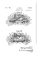
1935- H. R. GEI-:R
ROLLING MIKLL GUIDE 6 sheets-smet 1 Filed April 1, 1951 m. L 1935, H, R. GEER 2? ROLLING MILL GUIDE Filed April l, 1951 6 Sheets-Sheet 2 f4, la y im L, 1935 H. R. GEER 29ml@ ROLLING MILL GUIDE Filed April 1, 1951 6 Sheets-Sheet 3 mi. I, 935. i H R @EER 2,016,141
ROLLING MILL GUIDE Filed April 11951 6 Sheets-Sheet 4 a? ly- 9- 9 06667652 7 l El, 1935. H; R. GEER ROLLING MILL GUIDE Filed April' I, 1951 e sheets-sheet `5 0C@ 1 1935. Hl R @EER 2,016,141
ROLLING MILL GUIDE Filed April 1, 1951 6 Sheets-Sheet 6 Patented Oct. 1, 1935 UNITED STATES PATENT CFFICE ROLLING MILL -GUIDE Sylvania Application April 1, 1931, Serial No. 526,845
20 Claims.
My invention relates to rolling mill apparatus and more especially to the guide vequipment therefor and is applicable to metal rolling mills having stands of rolls known as two-high and threehigh mills, and is particularly adapted for use in connection with two-high mills of the continuous type for guiding bars or other sections of metal to and from the reducing and forming rolls.
Although my invention is adapted for use in l0 connection with mills of different types, I will for simplicity of description refer to the rolled piece of metal which is to be guided by my apparatus to the passes of the several stands of rolls, .as a bar, but I wish it understood that my apparatus is equally adapted to handle blooms, bi1- lets, slabs, beams, channels, angles, Ts, rails, flats, ovals, half-ovals, and in fact, any metal or material which is formed or operated upon by rolls, two different forms of said sections of which are illustrated in the drawings accompanying this specication.
In continuous mills having a succession of roll stands each having sets of rolls with passes formed therein for reducing bars in more than one direction, require twisting means whereby the axis of the bar being rolled is rotated usually about 90 between the succession of passes.
In former times stationary guides having in their length a winding or twisted passage Were commonly employed for this purposebut owing to the tendency of these guides to scratch the hot bars in passage, and also because of the rapidity with which these twisted passages lose their shape and have to be frequently replaced or repaired, during which time the entire mill must be shut down, a more desirable form of twisting means was required.
In recent times roller twisters have been designed to be used with one of the several roll passes in a set of rolls, but owing tothe restricted space into which guides must fit necessitates small rollers and shafts wholly out of proportion to the loads to be carried, therefore the maintenance cost is excessive and the shifting to other passes time consuming and costly.
My apparatus is adapted for use in connection with what is known as tandem continuous mills in which the axes of the rolls are substantially parallel to each other, one pair in front of the next pair and at comparatively short distances apart, whereby the bar is simultaneously reduced in a number of pairs of rolls, or it may be used in lconnection with tandem mills in which the successive pairs of rolls are placed with their axes parallel to each other, one pair in front of the next pair at considerable distance apart, and it is also equally applicable for use in connection with what is known as a train of rolls, that is, a number of pairs of reducing rolls arranged with their axes approximately in line 5 with each other.
My apparatus may be employed in connection with repeaters or roll trains in cases where it is desired to facilitate the passage of the bar around 1 or through the repeaters, by twisting the bar so 10 that the major axis of its cross-section becomes vertical and therefore offers the least resistance to bending in an approximately horizontal plane, whereby it is easily looped from one pass to the next. l5'
In some cases it is preferable that the bar should be in two or mo-re reducing passes of the rolls at the same time, thereby accomplishing the work of reducing while the bar is hot y and minimizing the travel of the same during 20" the rolling process, and this is accomplished by having the roller twisting guides and repeaters, if repeaters are used, near the reducing rolls.
I consider it essential that my roller twisting guide construction should be readily demountable 25 to facilitate the removal of a bar therefrom which may have been improperly reduced or distorted in the rolls, such a bar being known as a cobble.
My design of roller twisting guides embraces a pair of parallel rollers about the same length 30 as the mill rolls, on which are mounted pairs of opposed collars for each line of roll-passes. These parallel rollers are mounted on shafts carriedAon vertical walking beams and provided with adjusting means for shifting the rolls length- 35 wise, oppositely, with reference to each other. The collars are removably mounted on the rollers and may be of several forms to accommodate pass shapes, as rectangles, diamond, ovals, etc. and the adjustment makes it possible to impart 40 any desired twist angularity. It is possible with my device to so equip a stand of rolls that any section from it may be twisted or rotated and to suitably align the forward end of the bar to enter the pass in the next set of rolls. 45
One of the objects of my invention relates to mounting the twisting guides in such a manner that each pair of coacting collars forming the sides of the guides for the bar can be simultaneously adjusted longitudinally without chang- 50 ing the centers between the collars thereby increasing or diminishing the angle of twist of the bar being rolled in vorder to make the forward end of the bar register correctly with ,the i next roll pass. 55
v Another` object of my invention relates to mounting the roller twisting guides in such a manner as to impart a greater twist angularity to the bar than required and interposed stationary twist guides having less twisting angle capacity than the minimum required having means for simultaneously adjusting the twisting rolls longitudinally in both directions, and means for adjusting the twisting rollers independent of each other.
Another object of my invention relates to forming the roller twisting guides with a plurality of removable collars mounted thereon, each collar mounted on one twisting roller cooperating with a collar mounted on the other twisting roller to form a guide for the bar being rolled, thereby forming a unit construction for a plurality of roll passes.
Another object of my invention relates to the manner of mounting the roller twistingr guide unit to the rest bar so it can be quickly attached or detached from the roll housings when desired.
Another object of my invention relates to the means for adjusting the roller twisting guides whereby the angle of rotation of the bar being twisted may be varied while it is in transit.
Another object of my invention relates to the interchangeable collars and fastening means whereby the twisting mechanism may be adapted to roll passes of Varying sizes and shapes.
Another object of my invention relates to a twisting mechanism of unitary structure mounted opposite the roll passes having primary stationary twisting guides and secondary roller twisting, guides in which the primary set of guides ceases to function as twisters after the bar end enters the secondary set of twisters.
I-Iaving thus given a general description oi my invention, I will now, in order to make the same more clear, refer to the annexed six sheets oi drawings forming a part of this specication and in which like characters indicate like parts.
Figure l is a vertical transverse section taken centrally through two stands of rolls of a twohigh continuous wire and rod rolling mill illustrating one form of my improved roller twisting guides in end elevation attached to one or" the roll housings;
Fig. 2 is a transverse section taken on the line 2 2 of Fig. 6;
Fig. 3 is a detail view illustrating the shape and number of the roll passes in the pair of rolls 3;
Fig. 4 is a detail section taken on the line i-t of Fig. 6; Y
Fig. 5 is a front elevation of my roller twisting guides as illustrated in Fig. 1 with parts broken away to more clearly illustrate the mannerrof mounting the rollers;
Fig. 6 is a top plan view of the roller and stationary twisting guides of the construction illustrated in Fig, 5;
Fig. '7 is an Vend elevation of the construction shown in Figures 5 and 6 the mechanism being attached to the roll housing with the rolls in section;
Fig. 8 is a front elevation of the stationary twisting guides and rest bar;
Fig. 9 is a vertical longitudinal section taken on the line 9-9 of Fig. 1l illustrating a` modified 'form of roller twisting guide for twisting and guiding bars of larger section;
Fig. 10 is a front elevation of the roller twisting guide unit as illustrated in Fig. 9; A. Fig. 11 is an end elevation of the construction modified form of mounting the roller twisting 5 guides;
Fig. 13 is a top plan View of the form of roller twisting guides illustrated in Fig. 12;
Fig. 14 is Van end elevation of the construction shown in Figs. 12 and 13; and, 10 Fig. 15 is a detail section taken on the line IE5- I5 of Fig, 13.
Referring now in detail to the various characters of reference on the drawings and first to Figs. 1 to 8 inclusive, Vthe numerals I and 2 indi- 15 cate the roll housing of two stands of a continuous rolling mill type of a wire and rod mill, in this mill the plurality oi roll stands are placed close together but this detail will be Varied in continuous mills of different types. 3 and 4 des- 20 ignate the pairs of rolls for the two stands respectively, each preferably having a plurality of passes formed therein as indicated at 5 in Fig. 3, for the pair of rolls 3. In this figure a bar 5 rectangular in cross-section is fed into 25 thel entering guides 1, and through one of the passes 5 and reduced as indicated to a substantially diamond shaped bar 8 in cross-section, having its major axes horizontally disposed as it leaves `the pass 5, although Vit will be readily 30 understood that the roll passes may be formed to produce other shapes as ovals, flats, etc.
A rest. bar 9 having brackets I D at each end formed integral therewith is attached to the roll housings II of the roll stand I opposite the 35.'
passes 5 by means of bolts I2 and I3 the heads of which engage the T-slots Iii inthe roll housing. As indicated in Fig. 8 the holes in the brackets I9 for the passage of the bolts I2 and i3 are elongated to allow for a slight adjust- 40 ment of the rest bar 9 if required.
The top of the rest bar 9 is grooved as at I5 to receive the projections I6 formed on the stationary guides II, as clearly indicated in Figs. 6, 7 and 8. As shown in these iigures, each guide 45 has two twisting passageways I8 formed therein, one of each of which is adapted to be in alignment with one of the roll passes 5 and receive theY bars from the roll pass, although I wish it understood that these guides may be made with one 50 or a plurality of twisting pasageways if so desired. The guides are secured tothe rest bar 9 by means of bolts I9 which pass through` openings 29 and 2| in the rest bar and guides respectively. The bolts I9 being secured at their 55 upper ends by means of adjustable clamping clips 22 and set bolts'23. Extending outwardly from each of the brackets I0 is a boss 24 perforated as at 25 for the passage of the bolts I2 by means of which the roller twisting unit is secured there- 60 to. Awalking beam 26 comprising a pair of spaced links 21 connected together centrally by means of a thimble 28 is pivotally mounted on each of the bosses 24 and a anged washer 29 engages the end of ea-ch of the bosses and extend over 65 the side face of the walking beam and held in position by means of a nut 30 screwed on the end of the bolt I2.
Between the outer ends of the links 21 of the walking beams 26 are pivoted bearing blocks 3l 70 and 32 by means of bolts 33 for supporting the ends of the shafts of the roller twisting guides, the rollers for which are similarly constructed and mounted., These shafts 34 and 35 have their ends supported in the bearing blocks 3| and 32, 75
each having at an intermediate point an annular shoulder 36 formed integral with the shafts or rigidly .secured thereto, forming an abutment for an anti-friction bearing 31. Another anti-friction bearing 38 is mounted on each shaft 34 and 35 in spaced relation to the anti-friction bearing 31 and held in position by means of an annular ring 39 and adjustable nut 40 screwed on the threaded portion 4| of the shafts. In order to hold the nuts 49 in their adjusted position the outer surface of the nuts are milled for a portion of their lengths to engage a set screw 4| which is threaded into an overhanging projecting lug 42 formed integral with, and extending from the inner edge of each of the bearing blocks 3|.
The outer ends of the shafts 34 and 35 are screw threaded as at 43 and 44 to receive nuts 45 which are adapted to be screwed tight against the outer surface of the bearing blocks 3| and 32 for holding the shafts in a fixed position. These nuts also serve the purpose for longitudinal adjustment of the shafts. A roller 46 is mounted on the anti-friction bearings 31 and 38 of each of the shafts 34 and 35 having an annular ilange 41 at one end and a plurality of coacting removable collars 48 having inclined side faces 49 adapted to form guides between the same. These collars are spaced apart by means of annular rings 50 and a nut 5| is screwed on the opposite end of the roller to that of the flange 41 for clamping the parts in the desired position. An annular space 52 is formed between the antifriction bearings 31 and 38 which is supplied with oil through a duct 53 in the shafts and packing glands 54 at the ends of the rollers 46 prevents the oil from escaping from the rollers.
One of the brackets I0 of the rest bar 9 has a anged end 55 bifurcated as at 56 and adapted to form a bearing to receive the annular grooved portion 51 of a nut 58 having an outer toothed or fluted portion 59 for engaging the tooth 60 of the wrench 6I. This wrench 6| has a flanged projection 62 adapted when the wrench is not in use to extend through a notch 63 in the upper surface of the anged end 55 of the bracket I0, and has a locking pin 64 extending through a hole near the end of the projection 62 for retaining the wrench in position. The pin 64 secured to the wrench to prevent loss by means of a chain 65. When it is desired to use the wrench the pin 64 is removed from the hole in the projection 62, the wrench can then be removed from the fluted end portion 51 of the nut 56 and reversed as indicated in dotted lines in Fig. 5, the nut can then be rotated in either direction to simultaneously adjust both of the rollers 45 longitudinally in either direction, thereby varying the space between the collars 48 on the one roll and those on the other to increase or decrease the angular twist of the bar as it passes through the guide formed between the collars.
The inclined face of each collar on one of the rollers 45 coact with an opposed inclined face of another collar on the other roller to form a guide between the same which is in alignment with one of the passageways I8 formed in the stationary guides I1 and receives the bar after its passage through the roll pass. It will be noted that as the rollers are adjusted longitudinally by means of the wrench 59 and rotating nut 5S that the centers between the coacting collars 48 will always remain in a xed position as indicated in Figs. 5 and 9 of the drawings, in such a manner `that when the guide-ways between the coacting collars on the rollers are properly adjusted in alignment with a plurality of roll passes one or more of the roll passes may be used without adjusting the roller twisting guides, or in case any adjustment is necessary it 25 can be quickly done by means of the wrench.
If desired the collars may be adjusted during the passage of the bar through the guides to give a greater or less twist to the bar to properly align the forward end of lthe bar for the next 10 roll pass.
In the operation of my twisting mechanism the rectangular bar 6 is fed forward and enters the pass 5 in the pair of rolls 3 whi-ch reduces its cross-section area to a substantially diamond 15v shaped bar 8 in cross-section with its major axes horizontally disposed. The bar 8 then enters the twisting passageway I8 in the stationary guides I1 and is given an initial twist of the required angle of rotation. The bar then passes 20 between the rollers 46 having a pair of collars 48 mounted thereon having opposed coacting inclined side faces 49 which form the sides of the twisting guide for the bar 8', the space between the collars 48 with their inclined surfaces being 25 so adjusted as to give the final angular twist to the bar to properly align the forward end of the bar to enter the next roll pass. It will be noted that the passageway I8 in the stationary guide is of greater width than the thickness of the 3() bar 8 and that the final twisting of the bar as it passes between the roller twisters 46 at this point lifts the bar from the sides of the passageways I8 in such a manner that the passageway ceases to function as a twisting guide and removes all 35 rubbing action for the remainder of the bars length.
In Figs. 9, 10 and 11 I have illustrated a modified form of a roller twisting guide for twisting or rotating bars of larger size than those shown o in the construction illustrated in Figs. l to 8 in which two pairs of coacting collars 66 having inclined faces are shown mounted on rollers 61. The collars 66 are removably secured to the rollers 61 by means of segmental or split wedge blocks 5, 68, which are seated in an annular groove formed at intermediate points on the periphery of the rollers 61 with the inclined surfaces of the wedge blocks engaging the inclined recesses 19 of the collars and secured in position by means of bolts 69. The rollers 61 have anti-friction bearings 1| and 12 which are mounted on shafts 13 and 14 in a similar manner to those above described in Figs. 1, 5, 6 and '1. 'I'he ends of the shafts 13 and 14 are mounted in split bearing blocks 15 which are keyed thereto and pivoted by means of bolts 1S to'the bifurcated ends 11 of the walking beams 18 and held in position by means of nuts 19. The walking beams 18 are each formed in one piece and are each pivoted centrally as 60 at by means of a bolt 8| to an extending boss 82 on the bracket ends 83 of the rest bar 84. The bolt 8| does not extend into theT-slot 85 in the roll housing 86, as. in the construction illustrated in Figs. l, 2, 6 and '1, but is keyed as at 81 to the bracket ends 83 the opposite ends of each of said bolts 8| having a washer 88 and key 89 extending through a slot 99 for holding the walking beam 18 in position.
In case it is desired to remove the roller twistl0 ing guides as a unit 1t 1s only necessary 1n this construction to remove the keys 89 and the entire rotary twisting mechanism can be removed from the bolts 8|.
Bracket arms 9| and 92 extend outwardly from 75 the bracket ends 83 of the rest bar 84 for receiving the. adjusting mechanism for the roller twisting guides'. The bracket armV SI is perforated at the outer end, as at 93 to receive a thimble 5 94 having a plunger 95 with a head portion 96.
A spring 9.1 is mounted on the plunger 95 interposed between the head portion 96 and the end of the thimble to normally project the inner end of the plunger against one end of the shaft H14. The outer end of the plunger 95 extends through one end of the thimble as at 98 and has ay washer 99 mounted thereon and a cotter pin Il extends therethrough for holding the plunger in the desired' position. The bracket arm 92 has l'y'its outer end perforated asv at IGI for receiving a nut IilZ having a collar formed thereon asat L03 for engaging the side of the bracket arm 92.
An adjusting screw Ill having a hand wheel IIl5 on its outer end is screwed into the nut |02 zi'fiandV adapted to have its inner end engage the opposite end. of the shaft 'I4 to that of the plunger The spring pressed plunger 85 engages one end of the shaft 'I4 under tension and holds the op- 25=.1:posite end of the shaft at all times in contact with the inner end of the adjusting screw IEM, while-the rotation of the hand wheel MD5 ineither direction will adjust the guides in any desired position. Buffy The bracket ends 83 of the rest bar 84 are secured by means o-f bolts IE6 to. the roll. housing 86: the heads ofv which are inserted in the T- slots 85, the ends extending outwardly therefrom through elongated slots I'l in the bracket ends 35u83. The ends of the bolts have nuts threaded thereon as at Hi8 for securely clamping the rest bar 84 in position.
In Figs. 12 to 15 inclusive I have shown another slightly modified form of construction to those shown in Figs. l to 11. In this construction the twisting rollers |99 and collars III! are mounted in a similar manner to those shown in Figs. 9 to 11 the ends of the shafts III being mounted in split bearing blocks IIZ which are pivoted in the ,Y-bifurcated ends of the walking beams IIS and I I 4 and held against rotation by means of the bolts II5.
The walking beam IIB is formed with a projecting flange IIS having a. threaded opening for 50, receiving an adjusting bolt II'I. This adjusting bolt is adapted to contact with the ears IIB and i I9 formed integral with one of the bracket ends IZB of the rest bar I2I. By vertically adjusting the bolt III the twisting rollers Ide and collars I I0 forming the sides of the guides can be longitudinally adjusted to give the desired twist to the bar being rolled.
My twisting guides may be mounted on the roll housings of all the roll stands of a continuous rolling mill if desired but in some cases this is not necessary as illustrated in Fig. l of the drawings in this gure a square or rectangular bar 6 without being twisted or rotated, enters the roll pass 5 thereby reducing it to a substantially diamond shaped bar 8 in cross section, this bar has to be rotated 90 as indicated to enter the next pass which reduces it again to a square or rectangular bar in cross-section, this bar section will enter the next roll pass which may be similar toroll pass 5 but of smaller area without being4 rotated, but after passing through that roll pass the bar will have to be again rotated as indicated for bar S in order to give the proper working of the metal in reducing the bar.
75 I also wish it understood that my twisting mechanism would operate equally as well if applied to the entering side of the roll housing, or at an intermediate point between the stands of rolls. if desired.
Although I have described and illustrated my 'f5 invention in considerable detail, I do not wish to be limited to the exact and'specic details thereof as shown and described, but may use such modifications in, substitutions for, or equivalents thereof, as are embraced within the scope of my 16T invention, as pointed out in the claims.
Having thus described my invention what I claim as new and desire to secure by Letters Patent is:
l. A rolling mill guide comprising a pair of "v Walking beams, a pairof shafts carried by the walking beams, a roller mounted on each shaft, a collar mounted on each roller, the collar mounted on one roller coacting with the collar mounted on the other roller, and means for lon- 20'?? gitudinally adjusting the rollers.
2. A rolling mill guide comprising a pair of walking beams, a pair of shafts carried by the walking beams, a roller mounted on each shaft,
collars mounted on each roller, each collar 2li?l`l` mounted on one roller coacting with a collar mounted on the other roller to form a twisting guide therebetween, and means for simultaneously adjusting both of the rollers longitudinally.
3. A rolling mill guide comprising a pair of :'1
walking beams, a bearing secured to each end of the walking beams, a pair of shafts having their ends supported by the bearings, a roller mounted on each shaft, removable collars mounted on each roller, each collar mounted on one roller 353:1
ing their ends supported by the bearings, anti- 45,@
friction bearings mounted on the shafts, a roller mounted on the anti-friction bearings on each shaft, collars mounted on each roller, each collar mounted on one roller coactingwith the collar mounted on the other roller to form a guide 1 therebetween for a bar being rolled, and means for simultaneously adjusting both of the rollers longitudinally in opposite directions.
5. A rolling mill guide comprising a roll housing, a rest bar having bracket ends secured to the roll housing, a walking beam pivotally mounted on the bracket ends of the rest bar, bifurcated ends formed in the walking beams, a bearing pivoted between each of the bifurcated ends of the walking beams, a pair of shafts hav- 60,
ing their ends screw threaded and supported by the bearings, nuts on each end of the shafts for clamping the bearings to the shafts, a roller mounted on each shaft, collars mounted on each roller, each collar mounted on one roller coact- 65 ing with the collar mounted on the other roller to form a guide therebetween for a bar being rolled, and means 'for simultaneously adjusting both of the rollers longitudinally in opposite directions. 70 6. A rolling mill guide, comprising a pair of Walking beams, a pair of spaced rollers, shafts for the rollers having their ends screw threaded and supported by the walking beams, collars mounted on the rollers, an adjusting nut threaded on the end of one of Vthe shafts, and a wrench for engaging the nut and adapted to simultaneously adjust the rollers longitudinally in opposite directions.
7. A rolling mill guide, comprising a pair of Walking beams having bifurcated ends, a bearing block pivotally secured in each of the bifurcated ends of the walking beams, a pair of shafts having screw threaded extensions supported by lOithe bearing blocks, a nut on each of the screw threaded extensions adapted to engage one side of the bearing blocks and retain the shaft in an adjusted position, a roller mounted on each shaft, collars mounted on each roller, each collar on r' one roller coacting with the collar mounted on the other roller to form a guide therebetween, an adjusting nut having a iiuted surface mounted on the end portion of one of the shafts, and a wrench mounted thereon having a tooth for enggaging the fluted surface of the nut for adjusting the rollers.
8. A rolling mill guide, comprising a pair of rollers spaced apart and rotatably mounted, coacting collars having inclined side faces arranged in pairs mounted on the rollers, said inclined side faces of the pairs of coacting collars forming twisting guides adapted to twist a rolled bar, and means for longitudinally adjusting the coacting collars simultaneously whereby the angle of twist may be varied while the bar being twisted is in collars having nally in opposite directions.
10. The combination with a pair of rolls having a pass formed therein, a primary twister adapted to receive a rolled bar from the roll pass and give the bar an initial twist, a secondary twister comprising a pair of rollers, coacting collars having inclined side faces arranged in pairs mounted on the rollers andl forming guides adapted to complete the desired twist angularity of the bar and in which the primary set ceases to function as twisters after the bar engages the inclined faces of the collars forming the guides of the secondary twisters, and means for simultaneously longitudinally adjusting the coacting collars.
11. In a rolling mill, the combination of a roll housing, a rest bar secured to the roll housing, a roller twisting unit provided with a plurality of guides secured to the rest bar and the roll housing, means simultaneously operated for adjusting the width of the plurality of guides without bar, a twisting passageway in the stationary guides opposite each roll pass, an extending boss formed integral with each bracket end of the rest bar, a walking beam having bifurcated ends pivotally mounted on each boss, a bearing block pivotally mounted in each bifurcated end of the walking beams, a pair of shafts having their ends supported by the bearing blocks, a pair of anti-fric tion bearings mounted on each shaft, a fixedv shoulder for engaging one of the anti-friction bearings, a movable ring for engaging the other anti-friction bearing, a nut threaded on each shaft for engaging the movable ring, a set-screw for engaging each nut, a roller mounted on the anti-friction bearings on each shaft, collars mounted on each roller, each collar mounted on one roller coacting with a collar mounted on the other roller adapted to form a pass therebetween in alignment with the twisting passageways in the stationary guides, and means for simultaneously adjusting the rollers in opposite directions.
13. A rolling mill guide, comprising a pair of shafts, a roller rotatably mounted on each shaft, coacting collars mounted on each roller, twisting guides formed by the coacting collars, Walking beams for supporting the ends of the shafts, a nut on each shaft for holding the rollers in position on the shafts, a set screw for each nut for retaining the nut in its adjusted position, and means for simultaneously adjusting the rollers in opposite directions to each other.
14. A rolling mill guide, comprising a pair of rollers spaced apart and rotatably mounted, means for normally holding the rollers stationary in fixed relation to each other, a plurality of spaced collars having opposed inclined side faces detachably mounted on the rollers, each collar mounted on one roller coacting with a collar mounted on the other roller and adapted to form a twisting guide between each pair of opposed inclined side faces of the collars, and means for simultaneously adjusting the width of each pair of guides without changing the center of the guide.
15. In a rolling mill guide for twisting rolled bars, comprising a pair of normally fixed shafts, a roller rotatably mounted on each shaft, detachable collars mounted on each roller, each collar mounted on one roller having an inclined side face coacting with an Opposed inclined side face of a collar mounted on the other roller and adapted to form a twisting guide for engaging the opposite corner side edges of a rolled bar, and means for simultaneously adjusting the shafts and rollers mounted thereon in the reverse direction to each other.
16. In a rolling mill guide, comprising a rest bar, bracket ends formed on the rest bar, a walking beam pivotally secured to each of the bracket ends of the rest bar, a b earing block pivotally attached to each end of the walking beams, a pair of shafts having their ends supported in the bearing blocks, a roller rotatably mounted on each shaft, detachable collars mounted on the rollers, means for engaging the end of one of the shafts adapted to project the rollers longitudinally in one direction, and adjusting means engaging the opposite end of the shaft for longitudinally adjusting the rollers in the opposite direction.
17. In a rolling mill guide, comprising a rest bar, bracket ends formed on the rest bar, a walking beam pivoted centrally to each of the bracket ends of the rest bar, a bearing block pivotally attached to each end of the walking beams, a pair of shafts spaced apart having their ends supported in the bearing blocks and keyed thereto, a roller rotatably mounted on each shaft, detachable collars mounted on the rollers, an adjusting screw engaging the end of one of the shafts for longitudinally adjusting the rollers, and a spring pressed plunger engaging the opposite end of said shaft.
18. A rolling mill guide, comprising a rest bar, bracket ends formed on the rest bar, a pair of spaced ears extending from one of the bracket ends of the, rest bar, a Walking beam pivoted centrally to each of the bracket ends of the rest bar, a bearing block pivotally attached to each end of the Walking beams, a pair of shafts spac-ed apart having their ends supported in the bearing blocks, a roller rotatably mounted on each Y shaft, detachable collars mounted on the rollers,
rollers spaced apart and rotatably mounted, means for normally holding the rollers in xed relation to each other, spaced collars on the rollers adapted to form guides to twist a bar being rolled as it passes between the said rollers, and simultaneously operated means for longitudinally adjusting the rollers the same relative movement in opposite directions.
20. A rolling mill guide, comprising a pair of rollers spaced apart and rotatably mounted, 10'` coacting with the inclined surface of the collar 15 on the other roller and adapted to form a twisting guide therebetween, and means simultaneousf 1y operated for longitudinally adjusting the pair of rollers in relation to each other.
HARRY R. GEER.
Priority Applications (1)
| Application Number | Priority Date | Filing Date | Title |
|---|---|---|---|
| US526845A US2016141A (en) | 1931-04-01 | 1931-04-01 | Rolling mill guide |
Applications Claiming Priority (1)
| Application Number | Priority Date | Filing Date | Title |
|---|---|---|---|
| US526845A US2016141A (en) | 1931-04-01 | 1931-04-01 | Rolling mill guide |
Publications (1)
| Publication Number | Publication Date |
|---|---|
| US2016141A true US2016141A (en) | 1935-10-01 |
Family
ID=24099037
Family Applications (1)
| Application Number | Title | Priority Date | Filing Date |
|---|---|---|---|
| US526845A Expired - Lifetime US2016141A (en) | 1931-04-01 | 1931-04-01 | Rolling mill guide |
Country Status (1)
| Country | Link |
|---|---|
| US (1) | US2016141A (en) |
Cited By (7)
| Publication number | Priority date | Publication date | Assignee | Title |
|---|---|---|---|---|
| US3456473A (en) * | 1965-01-02 | 1969-07-22 | Wuppermann Gmbh Theodor | Tool for rounding edges of strip material |
| US3487671A (en) * | 1965-02-22 | 1970-01-06 | Wendel & Cie Sa De | Methods of and apparatus for rolling structural shapes such as h,i and rails |
| US3776013A (en) * | 1972-05-25 | 1973-12-04 | Ferroco Eng Ltd | Bar twister guide |
| US3817072A (en) * | 1971-04-17 | 1974-06-18 | Morgan Construction Co | Twisting apparatus |
| US3818744A (en) * | 1971-11-18 | 1974-06-25 | Copper Refineries Pty Ltd | Method of, and entry-guide for, feeding stock to a rod-rolling reduction mill |
| US3911714A (en) * | 1973-08-23 | 1975-10-14 | Nippon Kokan Kk | Method of automatically rotating a hollow shell in a plug mill |
| US4091860A (en) * | 1971-12-23 | 1978-05-30 | Southwire Company | Wheel spreader and crack closer |
-
1931
- 1931-04-01 US US526845A patent/US2016141A/en not_active Expired - Lifetime
Cited By (7)
| Publication number | Priority date | Publication date | Assignee | Title |
|---|---|---|---|---|
| US3456473A (en) * | 1965-01-02 | 1969-07-22 | Wuppermann Gmbh Theodor | Tool for rounding edges of strip material |
| US3487671A (en) * | 1965-02-22 | 1970-01-06 | Wendel & Cie Sa De | Methods of and apparatus for rolling structural shapes such as h,i and rails |
| US3817072A (en) * | 1971-04-17 | 1974-06-18 | Morgan Construction Co | Twisting apparatus |
| US3818744A (en) * | 1971-11-18 | 1974-06-25 | Copper Refineries Pty Ltd | Method of, and entry-guide for, feeding stock to a rod-rolling reduction mill |
| US4091860A (en) * | 1971-12-23 | 1978-05-30 | Southwire Company | Wheel spreader and crack closer |
| US3776013A (en) * | 1972-05-25 | 1973-12-04 | Ferroco Eng Ltd | Bar twister guide |
| US3911714A (en) * | 1973-08-23 | 1975-10-14 | Nippon Kokan Kk | Method of automatically rotating a hollow shell in a plug mill |
Similar Documents
| Publication | Publication Date | Title |
|---|---|---|
| US2016141A (en) | Rolling mill guide | |
| US2004596A (en) | Method and apparatus for manufacturing metal sheets and strips | |
| US3533263A (en) | Multi-roll stands | |
| US3420082A (en) | Leveler | |
| US3459023A (en) | Rolling mill | |
| US3326027A (en) | Roller receiving guide | |
| US2012074A (en) | Entry guide | |
| US2030816A (en) | Feed table for sheets | |
| US1890342A (en) | Sheet flattener | |
| US4387584A (en) | Steel pipe rolling mill | |
| US3815203A (en) | Apparatus for applying fins to stationarily held pipes by means of entrainment members | |
| US2619030A (en) | Adjustable stamping machine | |
| US3540251A (en) | Cross-roll straightener drive assembly | |
| US1680105A (en) | Repeater for rolling mills | |
| US1911028A (en) | Tube bending device | |
| US1157378A (en) | Metal-rolling apparatus. | |
| US1968865A (en) | Apparatus for cutting metal | |
| US3577758A (en) | Apparatus for extracting chocks, guides, and couplings from roll assemblies | |
| US2090706A (en) | Edge rolling method and apparatus | |
| US4483169A (en) | Double roller guide for rolling mills | |
| US2206759A (en) | Cross rolling | |
| US3344642A (en) | Rolling mill bar twisting apparatus | |
| US1488909A (en) | Rolling mill | |
| US2481138A (en) | Adjustable roll mounting | |
| US1762307A (en) | Conveying mechanism |