US20160331382A1 - Devices and methods for occlusion of an atrial appendage - Google Patents
Devices and methods for occlusion of an atrial appendage Download PDFInfo
- Publication number
- US20160331382A1 US20160331382A1 US15/154,695 US201615154695A US2016331382A1 US 20160331382 A1 US20160331382 A1 US 20160331382A1 US 201615154695 A US201615154695 A US 201615154695A US 2016331382 A1 US2016331382 A1 US 2016331382A1
- Authority
- US
- United States
- Prior art keywords
- frame
- elongate members
- center frame
- face
- face portion
- Prior art date
- Legal status (The legal status is an assumption and is not a legal conclusion. Google has not performed a legal analysis and makes no representation as to the accuracy of the status listed.)
- Granted
Links
- 238000000034 method Methods 0.000 title claims abstract description 33
- 210000001008 atrial appendage Anatomy 0.000 title description 6
- 239000012528 membrane Substances 0.000 claims description 82
- 210000005248 left atrial appendage Anatomy 0.000 claims description 58
- 230000004044 response Effects 0.000 claims description 41
- 230000033001 locomotion Effects 0.000 claims description 39
- 239000000463 material Substances 0.000 claims description 35
- 208000007536 Thrombosis Diseases 0.000 claims description 32
- 230000007704 transition Effects 0.000 claims description 27
- 229910001000 nickel titanium Inorganic materials 0.000 claims description 23
- HLXZNVUGXRDIFK-UHFFFAOYSA-N nickel titanium Chemical compound [Ti].[Ti].[Ti].[Ti].[Ti].[Ti].[Ti].[Ti].[Ti].[Ti].[Ti].[Ni].[Ni].[Ni].[Ni].[Ni].[Ni].[Ni].[Ni].[Ni].[Ni].[Ni].[Ni].[Ni].[Ni] HLXZNVUGXRDIFK-UHFFFAOYSA-N 0.000 claims description 23
- 230000015572 biosynthetic process Effects 0.000 claims description 17
- 230000000116 mitigating effect Effects 0.000 claims description 11
- 238000004873 anchoring Methods 0.000 claims description 10
- 230000007423 decrease Effects 0.000 claims description 8
- 239000012530 fluid Substances 0.000 claims description 6
- 229920000295 expanded polytetrafluoroethylene Polymers 0.000 claims description 5
- 238000011282 treatment Methods 0.000 claims description 4
- 239000000853 adhesive Substances 0.000 claims description 3
- 230000001070 adhesive effect Effects 0.000 claims description 3
- 230000002401 inhibitory effect Effects 0.000 claims description 2
- 239000000306 component Substances 0.000 description 71
- 210000004027 cell Anatomy 0.000 description 21
- 230000017531 blood circulation Effects 0.000 description 16
- 210000004369 blood Anatomy 0.000 description 15
- 239000008280 blood Substances 0.000 description 15
- 238000013461 design Methods 0.000 description 15
- 238000012876 topography Methods 0.000 description 15
- 210000005246 left atrium Anatomy 0.000 description 12
- 238000005259 measurement Methods 0.000 description 11
- 238000006073 displacement reaction Methods 0.000 description 10
- 230000002093 peripheral effect Effects 0.000 description 7
- 238000007789 sealing Methods 0.000 description 7
- 230000000747 cardiac effect Effects 0.000 description 6
- 238000011068 loading method Methods 0.000 description 6
- 230000008569 process Effects 0.000 description 6
- 239000004812 Fluorinated ethylene propylene Substances 0.000 description 5
- 210000003484 anatomy Anatomy 0.000 description 5
- 238000002513 implantation Methods 0.000 description 5
- 229920009441 perflouroethylene propylene Polymers 0.000 description 5
- 229920000642 polymer Polymers 0.000 description 5
- 238000013175 transesophageal echocardiography Methods 0.000 description 5
- 210000001124 body fluid Anatomy 0.000 description 4
- 229910003460 diamond Inorganic materials 0.000 description 4
- 239000010432 diamond Substances 0.000 description 4
- 229920002313 fluoropolymer Polymers 0.000 description 4
- 239000004811 fluoropolymer Substances 0.000 description 4
- 238000011065 in-situ storage Methods 0.000 description 4
- 230000004048 modification Effects 0.000 description 4
- 238000012986 modification Methods 0.000 description 4
- 206010014498 Embolic stroke Diseases 0.000 description 3
- 239000011248 coating agent Substances 0.000 description 3
- 238000000576 coating method Methods 0.000 description 3
- 230000006378 damage Effects 0.000 description 3
- 208000014674 injury Diseases 0.000 description 3
- 230000005012 migration Effects 0.000 description 3
- 238000013508 migration Methods 0.000 description 3
- 238000005498 polishing Methods 0.000 description 3
- -1 polytetrafluoroethylene Polymers 0.000 description 3
- 238000002360 preparation method Methods 0.000 description 3
- 230000008733 trauma Effects 0.000 description 3
- 206010003658 Atrial Fibrillation Diseases 0.000 description 2
- 229910000831 Steel Inorganic materials 0.000 description 2
- 230000004888 barrier function Effects 0.000 description 2
- 230000008901 benefit Effects 0.000 description 2
- 239000000560 biocompatible material Substances 0.000 description 2
- 230000023555 blood coagulation Effects 0.000 description 2
- 239000012503 blood component Substances 0.000 description 2
- 230000001112 coagulating effect Effects 0.000 description 2
- 238000005520 cutting process Methods 0.000 description 2
- 210000002889 endothelial cell Anatomy 0.000 description 2
- 230000002708 enhancing effect Effects 0.000 description 2
- 239000007943 implant Substances 0.000 description 2
- 238000002347 injection Methods 0.000 description 2
- 239000007924 injection Substances 0.000 description 2
- 230000001788 irregular Effects 0.000 description 2
- 238000003698 laser cutting Methods 0.000 description 2
- 210000000056 organ Anatomy 0.000 description 2
- 230000004962 physiological condition Effects 0.000 description 2
- BASFCYQUMIYNBI-UHFFFAOYSA-N platinum Chemical compound [Pt] BASFCYQUMIYNBI-UHFFFAOYSA-N 0.000 description 2
- 239000005020 polyethylene terephthalate Substances 0.000 description 2
- 229920001296 polysiloxane Polymers 0.000 description 2
- 229920001343 polytetrafluoroethylene Polymers 0.000 description 2
- 239000004810 polytetrafluoroethylene Substances 0.000 description 2
- 210000005245 right atrium Anatomy 0.000 description 2
- 239000010959 steel Substances 0.000 description 2
- 239000000126 substance Substances 0.000 description 2
- 230000037303 wrinkles Effects 0.000 description 2
- 229920002134 Carboxymethyl cellulose Polymers 0.000 description 1
- 229920004934 Dacron® Polymers 0.000 description 1
- JOYRKODLDBILNP-UHFFFAOYSA-N Ethyl urethane Chemical compound CCOC(N)=O JOYRKODLDBILNP-UHFFFAOYSA-N 0.000 description 1
- HTTJABKRGRZYRN-UHFFFAOYSA-N Heparin Chemical compound OC1C(NC(=O)C)C(O)OC(COS(O)(=O)=O)C1OC1C(OS(O)(=O)=O)C(O)C(OC2C(C(OS(O)(=O)=O)C(OC3C(C(O)C(O)C(O3)C(O)=O)OS(O)(=O)=O)C(CO)O2)NS(O)(=O)=O)C(C(O)=O)O1 HTTJABKRGRZYRN-UHFFFAOYSA-N 0.000 description 1
- 206010061218 Inflammation Diseases 0.000 description 1
- 239000003146 anticoagulant agent Substances 0.000 description 1
- 239000003080 antimitotic agent Substances 0.000 description 1
- 229960004676 antithrombotic agent Drugs 0.000 description 1
- 206010003119 arrhythmia Diseases 0.000 description 1
- 230000006793 arrhythmia Effects 0.000 description 1
- 210000003157 atrial septum Anatomy 0.000 description 1
- 238000005452 bending Methods 0.000 description 1
- 230000009286 beneficial effect Effects 0.000 description 1
- 229920000249 biocompatible polymer Polymers 0.000 description 1
- 239000010839 body fluid Substances 0.000 description 1
- 239000007767 bonding agent Substances 0.000 description 1
- 239000001768 carboxy methyl cellulose Substances 0.000 description 1
- 235000010948 carboxy methyl cellulose Nutrition 0.000 description 1
- 239000008112 carboxymethyl-cellulose Substances 0.000 description 1
- 229940105329 carboxymethylcellulose Drugs 0.000 description 1
- 230000004663 cell proliferation Effects 0.000 description 1
- 230000006835 compression Effects 0.000 description 1
- 238000007906 compression Methods 0.000 description 1
- 238000010276 construction Methods 0.000 description 1
- 230000008602 contraction Effects 0.000 description 1
- 229920001577 copolymer Polymers 0.000 description 1
- 239000003246 corticosteroid Substances 0.000 description 1
- 229960002344 dexamethasone sodium phosphate Drugs 0.000 description 1
- PLCQGRYPOISRTQ-FCJDYXGNSA-L dexamethasone sodium phosphate Chemical compound [Na+].[Na+].C1CC2=CC(=O)C=C[C@]2(C)[C@]2(F)[C@@H]1[C@@H]1C[C@@H](C)[C@@](C(=O)COP([O-])([O-])=O)(O)[C@@]1(C)C[C@@H]2O PLCQGRYPOISRTQ-FCJDYXGNSA-L 0.000 description 1
- 239000003814 drug Substances 0.000 description 1
- 229940079593 drug Drugs 0.000 description 1
- 229940088679 drug related substance Drugs 0.000 description 1
- 229920001971 elastomer Polymers 0.000 description 1
- 239000000806 elastomer Substances 0.000 description 1
- 229910000701 elgiloys (Co-Cr-Ni Alloy) Inorganic materials 0.000 description 1
- 230000010102 embolization Effects 0.000 description 1
- 230000010595 endothelial cell migration Effects 0.000 description 1
- 238000005530 etching Methods 0.000 description 1
- HQQADJVZYDDRJT-UHFFFAOYSA-N ethene;prop-1-ene Chemical group C=C.CC=C HQQADJVZYDDRJT-UHFFFAOYSA-N 0.000 description 1
- 239000004744 fabric Substances 0.000 description 1
- 210000003191 femoral vein Anatomy 0.000 description 1
- 239000000835 fiber Substances 0.000 description 1
- 238000001914 filtration Methods 0.000 description 1
- 239000003102 growth factor Substances 0.000 description 1
- 238000010438 heat treatment Methods 0.000 description 1
- 229960002897 heparin Drugs 0.000 description 1
- 229920000669 heparin Polymers 0.000 description 1
- 238000001727 in vivo Methods 0.000 description 1
- 230000004054 inflammatory process Effects 0.000 description 1
- 230000000977 initiatory effect Effects 0.000 description 1
- 230000003993 interaction Effects 0.000 description 1
- 210000005240 left ventricle Anatomy 0.000 description 1
- 238000004519 manufacturing process Methods 0.000 description 1
- 239000000203 mixture Substances 0.000 description 1
- 230000003387 muscular Effects 0.000 description 1
- 229910000510 noble metal Inorganic materials 0.000 description 1
- 230000007170 pathology Effects 0.000 description 1
- 230000000704 physical effect Effects 0.000 description 1
- 229910052697 platinum Inorganic materials 0.000 description 1
- 229920000728 polyester Polymers 0.000 description 1
- 229920000139 polyethylene terephthalate Polymers 0.000 description 1
- 229920000098 polyolefin Polymers 0.000 description 1
- 229920002635 polyurethane Polymers 0.000 description 1
- 239000004814 polyurethane Substances 0.000 description 1
- 239000011148 porous material Substances 0.000 description 1
- 230000002265 prevention Effects 0.000 description 1
- 230000009467 reduction Effects 0.000 description 1
- 210000005247 right atrial appendage Anatomy 0.000 description 1
- 210000005241 right ventricle Anatomy 0.000 description 1
- 239000000523 sample Substances 0.000 description 1
- 238000007493 shaping process Methods 0.000 description 1
- 229910001220 stainless steel Inorganic materials 0.000 description 1
- 239000010935 stainless steel Substances 0.000 description 1
- 230000000153 supplemental effect Effects 0.000 description 1
- 229910052715 tantalum Inorganic materials 0.000 description 1
- GUVRBAGPIYLISA-UHFFFAOYSA-N tantalum atom Chemical compound [Ta] GUVRBAGPIYLISA-UHFFFAOYSA-N 0.000 description 1
- 230000001732 thrombotic effect Effects 0.000 description 1
- 230000000472 traumatic effect Effects 0.000 description 1
- 210000005166 vasculature Anatomy 0.000 description 1
- 230000029663 wound healing Effects 0.000 description 1
Images


Classifications
-
- A—HUMAN NECESSITIES
- A61—MEDICAL OR VETERINARY SCIENCE; HYGIENE
- A61B—DIAGNOSIS; SURGERY; IDENTIFICATION
- A61B17/00—Surgical instruments, devices or methods
- A61B17/12—Surgical instruments, devices or methods for ligaturing or otherwise compressing tubular parts of the body, e.g. blood vessels or umbilical cord
- A61B17/12022—Occluding by internal devices, e.g. balloons or releasable wires
- A61B17/12131—Occluding by internal devices, e.g. balloons or releasable wires characterised by the type of occluding device
- A61B17/12168—Occluding by internal devices, e.g. balloons or releasable wires characterised by the type of occluding device having a mesh structure
- A61B17/12172—Occluding by internal devices, e.g. balloons or releasable wires characterised by the type of occluding device having a mesh structure having a pre-set deployed three-dimensional shape
-
- A—HUMAN NECESSITIES
- A61—MEDICAL OR VETERINARY SCIENCE; HYGIENE
- A61B—DIAGNOSIS; SURGERY; IDENTIFICATION
- A61B17/00—Surgical instruments, devices or methods
- A61B17/12—Surgical instruments, devices or methods for ligaturing or otherwise compressing tubular parts of the body, e.g. blood vessels or umbilical cord
- A61B17/12022—Occluding by internal devices, e.g. balloons or releasable wires
- A61B17/12027—Type of occlusion
- A61B17/12031—Type of occlusion complete occlusion
-
- A—HUMAN NECESSITIES
- A61—MEDICAL OR VETERINARY SCIENCE; HYGIENE
- A61B—DIAGNOSIS; SURGERY; IDENTIFICATION
- A61B17/00—Surgical instruments, devices or methods
- A61B17/12—Surgical instruments, devices or methods for ligaturing or otherwise compressing tubular parts of the body, e.g. blood vessels or umbilical cord
- A61B17/12022—Occluding by internal devices, e.g. balloons or releasable wires
- A61B17/12099—Occluding by internal devices, e.g. balloons or releasable wires characterised by the location of the occluder
- A61B17/12109—Occluding by internal devices, e.g. balloons or releasable wires characterised by the location of the occluder in a blood vessel
-
- A—HUMAN NECESSITIES
- A61—MEDICAL OR VETERINARY SCIENCE; HYGIENE
- A61B—DIAGNOSIS; SURGERY; IDENTIFICATION
- A61B17/00—Surgical instruments, devices or methods
- A61B17/12—Surgical instruments, devices or methods for ligaturing or otherwise compressing tubular parts of the body, e.g. blood vessels or umbilical cord
- A61B17/12022—Occluding by internal devices, e.g. balloons or releasable wires
- A61B17/12099—Occluding by internal devices, e.g. balloons or releasable wires characterised by the location of the occluder
- A61B17/12122—Occluding by internal devices, e.g. balloons or releasable wires characterised by the location of the occluder within the heart
-
- A—HUMAN NECESSITIES
- A61—MEDICAL OR VETERINARY SCIENCE; HYGIENE
- A61B—DIAGNOSIS; SURGERY; IDENTIFICATION
- A61B17/00—Surgical instruments, devices or methods
- A61B17/12—Surgical instruments, devices or methods for ligaturing or otherwise compressing tubular parts of the body, e.g. blood vessels or umbilical cord
- A61B17/12022—Occluding by internal devices, e.g. balloons or releasable wires
- A61B17/12131—Occluding by internal devices, e.g. balloons or releasable wires characterised by the type of occluding device
- A61B17/12168—Occluding by internal devices, e.g. balloons or releasable wires characterised by the type of occluding device having a mesh structure
- A61B17/12177—Occluding by internal devices, e.g. balloons or releasable wires characterised by the type of occluding device having a mesh structure comprising additional materials, e.g. thrombogenic, having filaments, having fibers or being coated
-
- A—HUMAN NECESSITIES
- A61—MEDICAL OR VETERINARY SCIENCE; HYGIENE
- A61B—DIAGNOSIS; SURGERY; IDENTIFICATION
- A61B17/00—Surgical instruments, devices or methods
- A61B17/0057—Implements for plugging an opening in the wall of a hollow or tubular organ, e.g. for sealing a vessel puncture or closing a cardiac septal defect
- A61B2017/00575—Implements for plugging an opening in the wall of a hollow or tubular organ, e.g. for sealing a vessel puncture or closing a cardiac septal defect for closure at remote site, e.g. closing atrial septum defects
- A61B2017/00579—Barbed implements
-
- A—HUMAN NECESSITIES
- A61—MEDICAL OR VETERINARY SCIENCE; HYGIENE
- A61B—DIAGNOSIS; SURGERY; IDENTIFICATION
- A61B17/00—Surgical instruments, devices or methods
- A61B17/0057—Implements for plugging an opening in the wall of a hollow or tubular organ, e.g. for sealing a vessel puncture or closing a cardiac septal defect
- A61B2017/00575—Implements for plugging an opening in the wall of a hollow or tubular organ, e.g. for sealing a vessel puncture or closing a cardiac septal defect for closure at remote site, e.g. closing atrial septum defects
- A61B2017/00592—Elastic or resilient implements
-
- A—HUMAN NECESSITIES
- A61—MEDICAL OR VETERINARY SCIENCE; HYGIENE
- A61B—DIAGNOSIS; SURGERY; IDENTIFICATION
- A61B17/00—Surgical instruments, devices or methods
- A61B17/0057—Implements for plugging an opening in the wall of a hollow or tubular organ, e.g. for sealing a vessel puncture or closing a cardiac septal defect
- A61B2017/00575—Implements for plugging an opening in the wall of a hollow or tubular organ, e.g. for sealing a vessel puncture or closing a cardiac septal defect for closure at remote site, e.g. closing atrial septum defects
- A61B2017/00597—Implements comprising a membrane
-
- A—HUMAN NECESSITIES
- A61—MEDICAL OR VETERINARY SCIENCE; HYGIENE
- A61B—DIAGNOSIS; SURGERY; IDENTIFICATION
- A61B17/00—Surgical instruments, devices or methods
- A61B17/0057—Implements for plugging an opening in the wall of a hollow or tubular organ, e.g. for sealing a vessel puncture or closing a cardiac septal defect
- A61B2017/00575—Implements for plugging an opening in the wall of a hollow or tubular organ, e.g. for sealing a vessel puncture or closing a cardiac septal defect for closure at remote site, e.g. closing atrial septum defects
- A61B2017/00632—Occluding a cavity, i.e. closing a blind opening
-
- A—HUMAN NECESSITIES
- A61—MEDICAL OR VETERINARY SCIENCE; HYGIENE
- A61B—DIAGNOSIS; SURGERY; IDENTIFICATION
- A61B17/00—Surgical instruments, devices or methods
- A61B2017/00831—Material properties
- A61B2017/00867—Material properties shape memory effect
-
- A—HUMAN NECESSITIES
- A61—MEDICAL OR VETERINARY SCIENCE; HYGIENE
- A61B—DIAGNOSIS; SURGERY; IDENTIFICATION
- A61B17/00—Surgical instruments, devices or methods
- A61B2017/00982—General structural features
- A61B2017/00986—Malecots, e.g. slotted tubes, of which the distal end is pulled to deflect side struts
-
- A—HUMAN NECESSITIES
- A61—MEDICAL OR VETERINARY SCIENCE; HYGIENE
- A61L—METHODS OR APPARATUS FOR STERILISING MATERIALS OR OBJECTS IN GENERAL; DISINFECTION, STERILISATION OR DEODORISATION OF AIR; CHEMICAL ASPECTS OF BANDAGES, DRESSINGS, ABSORBENT PADS OR SURGICAL ARTICLES; MATERIALS FOR BANDAGES, DRESSINGS, ABSORBENT PADS OR SURGICAL ARTICLES
- A61L31/00—Materials for other surgical articles, e.g. stents, stent-grafts, shunts, surgical drapes, guide wires, materials for adhesion prevention, occluding devices, surgical gloves, tissue fixation devices
- A61L31/04—Macromolecular materials
- A61L31/048—Macromolecular materials obtained by reactions only involving carbon-to-carbon unsaturated bonds
Definitions
- the present disclosure relates to implantable medical devices that may be used to occlude apertures, conduits, spaces, organs, and other structures within a patient.
- Cardiac structures such as atrial appendages can contribute to cardiac blood flow disturbance, which is associated with a number of cardiac-related pathologies. For example, complications caused by blood flow disturbance within an appendage and associated with atrial fibrillation can contribute to embolic stroke.
- implantable medical devices that may be used to occlude apertures, conduits, space, organs and other structures within a patient, including structures within the heart.
- this disclosure provides occlusion devices that can be deployed into a patient. Deployment may occur using transcatheter techniques, although various deployment techniques are contemplated.
- the devices may be deployed into an atrial appendage of the patient.
- the heart has left and right atrial appendages.
- Various aspects of the present disclosure are directed toward occlusive devices that provide enhanced conformability of a frame of the device (including the occlusive face) relative to the atrial appendage walls under physiological conditions.
- the present disclosure is directed toward occlusive devices that may provide more complete and rapid closure of the appendages including improved sealing of the appendages around the ostium thereof, enhanced clinical outcomes including reduced thrombus formation, reduced occluder embolization, greater conformability, and enhanced clinical ease-of-use, patient safety, and overall efficacy.
- devices for placement in vessels, appendages, and openings in a body may include a unitary self-expanding frame having a proximal end, a distal end, and a longitudinal axis.
- the unitary self-expanding frame may include a face portion having a pre-loaded flat configuration and (i) a center frame portion arranged at the proximal end and (ii) a plurality of elongate members extending from the center frame portion, and a body portion.
- devices may include a membrane attached to the unitary self-expanding frame.
- the plurality of elongate members may be configured to bend or flex substantially in a plane orthogonal to the longitudinal axis and mitigate longitudinal movement of the face portion in response to a compressive force applied to the body portion of the unitary self-expanding frame.
- devices for placement in vessels, appendages, and openings in a body having an elongated configuration and a deployed configuration may include a nitinol cut-tube frame having a proximal end and a distal end.
- the nitinol cut-tube frame may include a face portion having a center frame portion arranged at the proximal end and including a plurality of arcs arranged around a circumference of the center frame portion, and a plurality of elongate members extending from the center frame portion, and a body portion.
- the devices may also include a membrane attached to the nitinol cut-tube frame.
- the center frame portion and the plurality of elongate members may form a substantially uniform surface, and the center frame portion may be configured to provide an attachment point for a delivery system for the device.
- methods of reducing thrombus formation in treatment of left atrial appendage of a patient may include positioning a transcatheter assembly through an ostium of the left atrial appendage.
- the methods may also include deploying a device from the transcatheter assembly, the device comprising: a unitary self-expanding frame having a proximal end, a distal end, and a longitudinal axis, the unitary self-expanding frame including a face portion having a center frame portion arranged at the proximal end and a plurality of elongate members extending from the center frame portion, a body portion arranged substantially orthogonal to the face portion, and a membrane attached to the unitary self-expanding frame, wherein the face portion and the membrane define an occlusive face of the device.
- the methods may include absorbing one or more forces from the left atrial appendage with thereby flexing the plurality of elongate members in a plane orthogonal to the longitudinal axis to mitigate longitudinal movement of the face portion in response thereto.
- FIG. 1A is a cross-sectional view of a human heart in which a delivery system is positioned in preparation for deployment of an occlusive device into a LAA of the heart, in accordance with various aspects of the present disclosure.
- FIG. 1B shows the configuration of FIG. 1A with the occlusive device deployed from the delivery system and positioned within the LAA, in accordance with various aspects of the present disclosure.
- FIG. 1C shows the configuration of FIG. 1A with the occlusive device deployed from the delivery system and positioned within a vessel, in accordance with various aspects of the present disclosure.
- FIG. 2 is a perspective view of an example frame for an occlusive device, in accordance with various aspects of the present disclosure.
- FIG. 3 is a top view of an illustration of an example face portion of an occlusive device, in accordance with various aspects of the present disclosure.
- FIG. 4A is a schematic representation of a top view of an example face portion of an occlusive device in a first configuration prior to a force being applied, in accordance with various aspects of the present disclosure.
- FIG. 4B is a top view of an illustration of the example face portion, shown in FIG. 4A , in a second configuration in response to the force being applied, in accordance with various aspects of the present disclosure.
- FIG. 5A is a side view of an illustration of another example frame of an occlusive device, in accordance with various aspects of the present disclosure.
- FIG. 5B is a side view of the example frame of an occlusive device with a curvature in the face portion, in accordance with various aspects of the present disclosure.
- FIG. 6A is a top view of an illustration of a portion of an example frame and center frame portion that may be included with an occlusive device, in accordance with various aspects of the present disclosure.
- FIG. 6B is a perspective view of the example frame and center frame portion shown in FIG. 6A , prior to flattening and similar to the as-loaded condition in the delivery system in accordance with various aspects of the present disclosure.
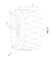
- FIG. 7 is a perspective view of an example occlusive device, in accordance with various aspects of the present disclosure.
- FIG. 8 is a perspective view of another example frame for an occlusive device, in accordance with various aspects of the present disclosure.
- FIG. 9A is a perspective view of another example frame for an occlusive device in a shape set configuration, in accordance with various aspects of the present disclosure.
- FIG. 9B is a side view of a strut cut pattern of the frame, shown in FIG. 9A , prior to deformation to the shape set configuration, in accordance with various aspects of the present disclosure.
- FIG. 10 is example flat pattern that can be used for forming a sheet material to create a frame of an occlusive device, in accordance with various aspects of the present disclosure.
- FIG. 11 is another example flat pattern that can be used for forming a sheet material to create a frame of an occlusive device, in accordance with various aspects of the present disclosure.
- FIG. 12 is a top view of an example center frame portion that may be included with an occlusive device, in accordance with various aspects of the present disclosure.
- FIG. 13 is a perspective view of an alternate design of an example frame for an occlusive device, in accordance with various aspects of the present disclosure.
- FIG. 14 is a perspective view of an alternate design of another example frame for an occlusive device, in accordance with various aspects of the present disclosure.
- FIG. 15 is a perspective view of an alternate design of another example frame for an occlusive device, in accordance with various aspects of the present disclosure.
- FIG. 16 is a perspective view of an alternate design of another example frame for an occlusive device, in accordance with various aspects of the present disclosure.
- FIG. 17 is a perspective view of an alternate design of another example frame for an occlusive device, in accordance with various aspects of the present disclosure.
- FIG. 18 is a perspective view of an alternate design of another example frame for an occlusive device, in accordance with various aspects of the present disclosure.
- FIGS. 1A-B are a cross-sectional views of a human heart 10 in which a delivery system 20 is positioned in preparation for deployment of an occlusive device 30 into an appendage 18 of the heart, in accordance with various aspects of the present disclosure.
- FIGS. 1A-B show a depiction of includes a right atrium 14 , a left atrium 16 , a right ventricle 32 , and a left ventricle 34 of the heart 10 .
- the appendage 18 is located in the left atrium 16 of the heart 10 , and thus, the appendage 18 may be considered the left atrial appendage 18 .
- the occlusive device 30 may be deployed in other appendages or openings within the human heart 10 or in other locations of the human body.
- the left atrial appendage 18 may be considered a muscular pouch extending from the anterolateral wall 36 of the left atrium 16 of the heart 10 , which serves as a reservoir for the left atrium 16 .
- the left atrial appendage 18 may contract rhythmically with the rest of the left atrium 16 during contraction of the heart 10 .
- the left atrial appendage 18 contracts with the left atrium 16 and pumps blood that may gather or collect within the left atrial appendage 18 to circulate therefrom.
- the left atrial appendage 18 may fail to sufficiently contract along with the left atrium 16 , which can allow blood to stagnate within the left atrial appendage 18 .
- Stagnant blood within the atrial appendage 18 is susceptible to coagulating and forming a thrombus, which can dislodge from the atrial appendage 18 and ultimately result in an embolic stroke.
- the occlusive device 30 may be delivered to the left atrial appendage 18 to help prevent and militate against blood stagnation within the left atrial appendage 18 .
- the occlusive device 30 may be delivered to the left atrial appendage 18 by way of a minimally invasive transcatheter procedure. More specifically, the delivery system 20 may be navigated through a vena cava 12 , into the right atrium 14 , through an atrial septum 15 , and into the left atrium 16 towards the appendage 18 .
- the percutaneous access to the patient's vasculature can be at the patient's femoral vein, for example. It should be understood that this example technique is merely one example, and many other access techniques can also be performed to deploy the occlusive devices provided herein.
- the occlusive device is contained within a lumen of the delivery system 20 , and is configured in a collapsed low-profile delivery configuration.
- transcatheter systems are generally shown and described, other delivery systems (e.g., thoracoscopic) are also contemplated.
- FIG. 1B shows the configuration of FIG. 1A with the occlusive device 30 deployed from the delivery system 20 and positioned within the left atrial appendage 18 , in accordance with various aspects of the present disclosure.
- a control catheter 22 may releasably couple to the occlusive device 30 , and is slidably disposed within the lumen of the delivery system 20 .
- the control catheter 22 can be used by a clinician operator to make the occlusive device 30 deploy from the delivery system 20 . For example, after positioning the occlusive device 30 through an ostium 38 of the left atrial appendage 18 , the clinician operator can retract the delivery system 20 in relation to the control catheter 22 to unsheath and deploy the occlusive device 30 .
- the ostium 38 may be considered a portion of the anterolateral wall 36 of the left atrium 16 from which a taper originates to form the pouch-like structure of the left atrial appendage 18 .
- the occlusive device 30 may include an occlusive face 40 that is arranged near the ostium 38 of the left atrial appendage 18 .
- the control catheter 22 may releasably couple to the occlusive device 30 via a hub or center frame portion or a plug (or the like) inserted into the center frame portion arranged centrally within the occlusive face 40 of the occlusive device 300 .
- the occlusive device 30 can reconfigure to an expanded configuration.
- the occlusive device 30 may expand to conform to the contours of the space defined within the left atrial appendage 18 .
- positioning of the occlusive device 30 relative to the ostium 38 of the left atrial appendage 18 may be enhanced and ensures that the occlusive device 30 prevents thrombus from embolizing from the left atrial appendage 18 .
- the occlusive face 40 may be arranged within the left atrial appendage 18 such that the occlusive face 40 connects portions of the anterolateral wall 36 on opposite sides of the ostium 38 to form a substantially uniform surface.
- blood may collect or stagnate along the face of a device implanted therein if the occlusive face is non-uniform (e.g., a device having a hub that protrudes beyond other portions of the occlusive face; a device having a occlusive face that is concave, partially concave, or includes depressions, a device having a occlusive face that is concave, partially concave, or includes depressions and a covering attached thereto that may drape or wrinkle as a result of the non-uniform face) relative to the ostium 38 of the left atrial appendage 18 or the occlusive face includes protuberances.
- non-uniform e.g., a device having a hub that protrudes beyond other portions of the occlusive face; a device having a occlusive face that is concave, partially concave, or includes depressions, a device having a occlusive face that is concave, partially concave, or includes depression
- thrombus may occur along the face of the occlusive device as a non-uniform surface may alter/disrupt the blood flow within the left atrium 18 .
- a patient may remain susceptible to blood coagulation and thrombus formation if an occlusive device includes a non-uniform surface as the result of improper positioning or the design of the device.
- the control catheter 22 can be decoupled from the occlusive device 30 , and the delivery system 20 and control catheter 22 can be removed from the patient.
- the occlusive device 30 deployed as shown, the space defined within the left atrial appendage 18 is essentially separated from the left atrium 16 by virtue of the physical barrier provided by the occlusive device 30 .
- stagnant blood within the LAA 18 that is susceptible to coagulating and forming thrombi may be prevented from entering the left atrium 16 , and thereby prevented from potentially causing an embolic stroke.
- positioning of the occlusive face 40 of the occlusive device 30 relative to the ostium 38 of the left atrial appendage 18 may help prevent blood collecting or stagnating along the face of the occlusive device 30 .
- FIG. 1C shows the configuration of FIG. 1A with the occlusive device 30 deployed from the delivery system and positioned within a vessel between the vessel walls 42 , in accordance with various aspects of the present disclosure.
- FIG. 2 is a perspective view of an example frame 200 for an occlusive device.
- the frame 200 may include a proximal end 202 and a distal end 204 , and may be unitary and self-expanding.
- the frame 200 may include a plurality of elongate members 206 and a center frame portion 208 arranged at the proximal end 202 of the frame 200 .
- the plurality of elongate members 206 may extend from the center frame portion 208 . Together, the combination of the plurality of elongate members 206 and the center frame portion 208 form a face portion 220 .
- the frame 200 may include a body portion 214 .
- the frame 200 including the plurality of elongate members 206 and the center frame portion 208 , is shown in a pre-loaded flat configuration. In certain instances and as discussed in further detail relative to FIGS. 5A-B , the frame 200 may be slightly bowed as a result of being loaded into and deployed from a delivery system. In the pre-loaded flat configuration and as shown, the plurality of elongate members 206 and the center frame portion 208 (the face portion 220 ) form a substantially planar surface (e.g., between 0 mm and 1 mm outward deflection measured from transition portions 216 ). In certain instances, the center frame portion 208 is a hole having an inner and outer circumference and a plurality of elongate members 206 radiate outward from the outer circumference of the center frame portion 208 .
- the face portion 220 may be formed by the center frame portion 208 and plurality of elongate members 206 .
- a boundary of the face portion 220 may be considered to be at transition portions 216 of the frame 200 .
- the transition portions 216 are arranged around a periphery of the face portion 220 .
- the transition portions 216 transition the frame 200 between the plurality of elongate members 206 and the body portion 214 are external to the face portion 220 . More specifically, the body portion 214 of the frame 200 extends from the plurality of elongate members 206 , and the transition portions 216 transitions the plurality of elongate members 206 of the frame 200 to the body portion 214 of the frame 200 .
- transition portions 216 may be configured as a landing zone that contact the walls of the appendage or vessel into which the frame 200 (as part of an occlusive device) is implanted.
- the transition portions 216 may enhance conformability of the frame 200 relative to the walls of the appendage or vessel.
- the body portion 214 may include any number of rows and cells.
- the body portion 214 may bifurcate to form multiple cells in a row, or the body portion 214 may extend directly to the distal end 204 of the frame.
- the body portion 214 may include cells formed of a five-sided shape, a six-sided shape, or other shapes such as, but not limited to, polygonal, square, rectangular, parallelogram-shaped, rhomboidal, trapezoidal, diamond-shaped, chevron-shaped, octagonal, triangular, and the like. Different shapes and arrangements of the body portion 214 are shown, for example, in FIGS. 13-18 .
- the plurality of elongate members 206 are configured to flex and mitigate longitudinal movement (relative to a longitudinal axis 212 of the frame 200 ) of the face portion 220 in response to a compressive force applied to the body portion 214 of the frame 200 .
- the force is applied to the transition portions 216 .
- the plurality of elongate members 206 may enhance fatigue resistance of the frame 200 by functioning as stress relief features that absorb flexure and/or torque, and the like, in response to one or more forces being applied to the frame 200 .
- the plurality of elongate members 206 configured to mitigate movement of the face portion 220 substantially outward from the plane, and movement outward from the plane may include outward deflection of the face portion 220 .
- the face portion 220 is a substantially uniform (proximal) surface formed by the plurality of elongate members 206 and the center frame portion 208 .
- the plurality of elongate members 206 and the center frame portion 208 may include an equal and constant surface across the face portion 220 .
- the plurality of elongate members 206 and the center frame portion 208 may be formed without protrusions outward from the face portion 220 .
- the plurality of elongate members 206 and the center frame portion 208 may include approximately equal thickness (relative to the longitudinal axis 212 ) across the face portion 220 .
- the face portion 220 having a substantially uniform surface or a surface without protrusions outward therefrom may enhance performance of an occlusive device that includes the frame 200 by mitigating the opportunity for thrombus formation.
- the substantially uniform surface of the face portion 220 may be planar.
- the plurality of elongate members 206 are configured to bend or flex substantially in a plane (formed by the face portion 220 ) orthogonal to the longitudinal axis 212 to mitigate longitudinal movement (relative to the longitudinal axis 212 of the frame 200 ) of the face portion 220 in response to a compressive force applied to the body portion 214 of the frame 200 .
- the force may be considered a compressive force, and the compressive force may be applied to one or more locations on the body portion 214 of the frame 200 .
- the compressive force may be non-uniform relative to the frame 200 , and in other instances the force may be considered a radial force, which may be defined as a force, or a component of a force, that is directed inwardly from one or more locations relative to the frame 200 .
- the force applied to one or more locations on the body portion 214 is directed along the body portion 214 toward the plurality of elongate members 206 .
- the plurality of elongate members 206 may absorb the applied force(s), and balance and/or share the applied force(s) throughout the frame 200 .
- the plurality of elongate members 206 bend or flex substantially in the plane orthogonal to the longitudinal axis 212 to mitigate movement of the face portion 220 (the combination of the plurality of elongate members 206 and the center frame portion 208 ) relative to the longitudinal axis 212 in response to a force applied to the frame 200 .
- the plurality of elongate members 206 flex and mitigate movement of the face portion 220 independent of the shape or arrangement of the body portion 214 of the frame 200 .
- Mitigating movement of the face portion 220 of the frame 200 may enhance performance of the frame 200 when implanted in a vessel or opening in a body. More specifically, when the frame 200 (or an occlusive device that includes the frame 200 ) is positioned within, for example, the contours of the space defined within a left atrial appendage (e.g., left atrial appendage 18 shown in FIGS. 1A-B or within a vessel as shown in FIG. 1C ), thrombosis may occur along an occlusive device in instances where a non-uniform surface alters a blood flow across the face of the device. Mitigating movement of the face portion 220 longitudinally decreases the opportunity for thrombus formation by avoiding disruption of the blood flow.
- a left atrial appendage e.g., left atrial appendage 18 shown in FIGS. 1A-B or within a vessel as shown in FIG. 1C
- Mitigating movement of the face portion 220 longitudinally decreases the opportunity for thrombus
- the face portion 220 having a substantially uniform surface or a surface without protrusions outward therefrom similarly enhances performance by avoiding disruption of the blood flow.
- occlusive devices having an occlusive face with depressions may not only disrupt blood flow by allowing blood to pool along the occlusive face but blood may collect within the depressions. Each of these instances may contribute to thrombus formation.
- such a device that includes depressions in the occlusive face may utilize a membrane to attempt to provide a uniform surface.
- the membrane may dip within the depression or wrinkle as a result of the non-uniform surface, and therefore disrupt blood flow across the occlusive face.
- the frame 200 including a uniform face portion 220 and also mitigating against movement of the face portion 220 in response to forces applied to the frame 200 may enhance performance of an occlusive device that includes the frame 200 by mitigating the opportunity for thrombus formation.
- the plurality of elongate members 206 being configured to flex and mitigate movement of the face portion 220 longitudinally relative to the longitudinal axis 212 may enhance the conformability of the frame 200 . More specifically, the plurality of elongate members 206 may facilitate the ability of the frame 200 , and more particularly the body portion 214 , to conform to irregular tissue topographies and/or dynamically variable tissue topographies. When the frame 200 is implanted into variable tissue topography, force applied from the tissue topography may be directed to one or more locations on the body portion 214 and/or the transition portions 216 .
- this force is directed along a length of the body portion 214 toward the plurality of elongate members 206 , and the plurality of elongate members 206 absorb the applied force(s), and balance and/or share the applied force(s) throughout the frame 200 .
- portions of the frame 200 that contact the variable tissue topography may conform thereto (as opposed to a frame forcing the variable tissue topography to conform to the shape of the frame).
- the transition portions 216 of the frame 200 may conform to the shape of an ostium when implanted.
- the frame 200 (which may include a membrane attached thereto) may be positioned within a left atrial appendage to help prevent thrombus from embolizing from the left atrial appendage (e.g., as shown above in FIG. 1B ). After implantation, portions of the frame 200 that contact the left atrial appendage conform thereto, and forces that are applied via the left atrial appendage may be absorbed by the plurality of elongate members 206 .
- the plurality of elongate members 206 are configured to maintain the face portion 220 on opposite sides of an ostium of the left atrial appendage to form and maintain a substantially uniform surface closing off the ostium while allowing the transition portions 216 and portions of the body portion 214 that contact the appendage are configured to conform to the shape of the appendage.
- conformability characteristics can be advantageous for providing substantial occlusion (sealing) and durable occlusion. Conformability can also enhance the fatigue resistance of the occlusive devices. Further, occlusive devices with substantial conformability are less traumatic to the patient and may tend to resist in situ migration better than occlusive devices with less conformability. In some embodiments of the occlusive devices provided herein, some portions of the devices are designed to be more conformable than other portions of the same device. That is, the conformability of a single occlusive device can be designed to be different at various areas of the device. Additionally, in some embodiments frame material selection, heat treatments and other treatments can be used to attain a desired extent of conformability. In certain instances, the frame 200 may be formed from nitinol (NiTi). In certain more specific embodiments, the frame 200 may be formed from a single unitary piece of nitinol.
- the frame 200 may be reconfigured to a low-profile (elongated) configuration for loading into a delivery catheter (e.g., such as the control catheter 22 shown in FIG. 1 -B) used for transcatheter deployment of the occlusive device.
- a delivery catheter e.g., such as the control catheter 22 shown in FIG. 1 -B
- the frame 200 is configured to self-expand and reconfigure to the configuration shown in FIG. 2 .
- the frame 200 may be expanded to conform to the contours of the space defined within the body (e.g., left atrial appendage 18 shown in FIGS. 1A-B or within a vessel as shown in FIG. 1C ).
- the center frame portion 208 may serve as the connection point to a control catheter for transcatheter deployment of the occlusive device.
- the frame 200 (and the occlusive device that includes the frame 200 ) may have a face portion 220 that is hubless (e.g., no addition structure or element beyond that of the center frame portion 208 , lacking in additional thickness beyond that of the center frame portion 208 , rimless, or lacking in dimension beyond a maximum thickness of the plurality of elongate members 206 and the center frame portion 208 ).
- the face portion 220 lacking a hub e.g., such as any eyelet that extends beyond the face portion 220 ) provides for an approximately uniform surface formed by the plurality of elongate members 206 and the center frame portion 208 .
- FIG. 2 The illustrative components shown in FIG. 2 are not intended to suggest any limitation as to the scope of use or functionality of embodiments of the disclosed subject matter. Neither should the illustrative components be interpreted as having any dependency or requirement related to any single component or combination of components illustrated therein. Additionally, any one or more of the components depicted in any of the FIG. 2 may be, in embodiments, integrated with various other components depicted therein (and/or components not illustrated), all of which are considered to be within the ambit of the disclosed subject matter.
- the frame 200 described with reference to FIG. 2 may be used in connection with delivery system 20 (shown in FIGS. 1A-B ).
- the frame 200 may form a portion of occlusive device 30 (e.g., with the plurality of elongate members 206 and the center frame portion 208 forming a portion of the occlusive face 40 ).
- the frame 200 may include a membrane attached thereto (e.g., as shown and discussed with reference to FIG. 7 ).
- FIG. 3 is a top view of an illustration of an example face portion 300 of an occlusive device, in accordance with various aspects of the present disclosure.
- the face portion 300 includes a plurality of elongate members 302 and a center frame portion 304 .
- the plurality of elongate members 302 may extend from the center frame portion 304 and include a common curvature within the face portion 300 , which is formed substantially within a common plane (e.g., the x-y plane, as shown).
- the common curvature may provide for the plurality of elongate members 302 to be non-overlapping within the face portion 300 .
- the plurality of elongate members 302 may have a zig-zag pattern (e.g., as shown in FIG. 8 ).
- the plurality of elongate members 302 may include any number of curvature or semi-curved patterns. Other curvature patterns are shown, for example, in FIGS. 8-11 . As shown, each of the plurality of elongate members 302 includes multiple curved sections. For illustrative purposes, the curved sections are highlighted for one of the plurality of elongate members 302 in FIG. 3 .
- the plurality of elongate members 302 may include a first curved section 306 , a second curved section 308 , and a third curved section 310 .
- the first curved section 306 and the third curved section 310 are curved in a first direction
- the second curved section 308 is curved in a second direction that is opposite that of the first direction.
- the plurality of elongate members 302 may include a first inflection point 318 between the first curved section 306 and the second curved section 308 , and a second inflection point 320 between the second curved section 308 and the third curved section 310 .
- the first inflection point 318 and the second inflection point 320 alter the curvature of the plurality of elongate members 302 .
- each of the first curved section 306 , the second curved section 308 , and the third curved section 310 are arranged within the common plane.
- the plurality of elongate members 302 , and the curvature formed by the first curved section 306 , the second curved section 308 , and the third curved section 310 occurs substantially within the x-y plane.
- each of the first curved section 306 , the second curved section 308 , and the third curved section 310 are curved within the x-y plane.
- the center frame portion 304 may also be arranged with the x-y plane.
- the plurality of elongate members 302 and the center frame portion 304 may be arranged within a common plane.
- the plurality of elongate members 302 are configured to flex and mitigate longitudinal movement (orthogonal to the x-y plane) of the face portion 300 in response to a compressive force applied to another portion of the occlusive device (e.g., as discussed above in detail with reference to FIG. 2 .).
- the plurality of elongate members 302 are configured to flex or bend substantially within the x-y plane to mitigate longitudinal movement (orthogonal to the x-y plane) of the face portion 300 .
- each of the first curved section 306 , the second curved section 308 , and the third curved section 310 may include equal radiuses of curvature.
- the first curved section 306 and the third curved section 310 may include a first radius of curvature
- the second curved section 308 may include a second (and different) radius of curvature.
- the (first) radius of curvature of the first curved section 306 and the third curved section 310 may be larger than the (second) radius of curvature of the third curved section 310 .
- the first curved section 306 and the third curved section 310 may include approximately equal lengths.
- the second curved section 308 may include a length that is equal to or greater than the first curved section 306 and the third curved section 310 .
- the first curved section 306 and the third curved section 310 may include lengths greater than the length of the second curved section 308 .
- the length of the second curved section 308 is greater than the first curved section 306 and the third curved section 310 , which are substantially equal in length.
- the plurality of elongate members 302 extend from the center frame portion 304 .
- a start point 312 for the plurality of elongate members 302 is arranged at the center frame portion 304
- an end point 314 for the plurality of elongate members 302 is arranged at a periphery of the face portion 300 .
- the start point 312 and the end point 314 is shown for one of the plurality of elongate members 302 in FIG. 3 .
- the start point 312 and the end point 314 may be symmetrically arranged with respect to the face portion 300 . More specifically, a tangent 316 formed between the start point 312 and the end point 314 may be substantially linear.
- the pattern of the curvature of the plurality of elongate members 302 may be symmetric such that the plurality of elongate members 302 include a curvature (having one or more inflection points) in a direction from the start point 312 and back in another direction to the end point 314 .
- the face portion 300 includes ten of the plurality of elongate members 302 .
- the face portion 300 may include two, three, four, five, six, seven, eight, nine, eleven, twelve, thirteen, fourteen, fifteen, sixteen, or more than sixteen of the plurality of elongate members 302 .
- the center frame portion 304 is shown to include ten peaks 322 that correspond to each of the plurality of elongate members 302 .
- the center frame portion 304 may include an equal number of peaks to the number of the plurality of elongate members 302 included with the face portion 300 . In other instances, the center frame portion 304 may include a substantially circular shape.
- the illustrative components shown in FIG. 3 are not intended to suggest any limitation as to the scope of use or functionality of embodiments of the disclosed subject matter. Neither should the illustrative components be interpreted as having any dependency or requirement related to any single component or combination of components illustrated therein.
- the face portion 300 may be integrated with various other occlusive devices depicted herein (and/or components not illustrated), all of which are considered to be within the ambit of the disclosed subject matter.
- the face portion 300 may be used in connection with the frame 200 shown in FIG. 2 .
- FIG. 4A is a schematic representation of a top view of an example face portion 400 of an occlusive device in a first configuration prior to a force being applied, in accordance with various aspects of the present disclosure.
- the face portion 400 includes a plurality of elongate members 402 a - j and a center frame portion 404 .
- the plurality of elongate members 402 a - j extend from the center frame portion 404 .
- the center frame portion 404 and the plurality of elongate members 402 a - j are arranged within an x-y plane.
- the plurality of elongate members 402 a - j and the center frame portion 404 may be formed from a unitary frame.
- the unitary frame may be formed by laser cutting (e.g., a tube or flat sheet), etching, wire forming, or other processes.
- the face portion 400 may be a substantially uniform surface or thickness.
- the plurality of elongate members 402 a - j and a center frame portion 404 may include an equal and constant surface across the face portion 400 such that the face portion 400 is without protrusions (e.g., relative to the z-axis).
- the face portion 400 having a substantially uniform surface or a surface without protrusions outward therefrom may enhance performance of an occlusive device that includes the frame 400 by mitigating against the disruption of blood flow across the face portion 400 thereby reducing the opportunity for thrombus formation.
- a peripheral boundary 406 of the face portion 400 is shown.
- the peripheral boundary 406 may be considered a non-physical boundary that is formed by end portions of the plurality of elongate members 402 a - j (e.g., the face portion 220 formed around the transition portions 216 as shown in FIG. 2 ).
- the peripheral boundary 406 may be a physical boundary formed by portions of a frame that form the face portion 400 .
- the face portion 400 may include a membrane attached thereto. Membranes are attached to provide a barrier for thrombus being embolized from appendage or vessel as well as to enhance sealing.
- Membranes suitable for use include occlusive or semi-occlusive materials.
- Embodiments with semi-occlusive materials may allow passage of some fluids/blood components while inhibiting the passage of thrombus.
- the peripheral boundary 406 may be formed by the boundary of the membrane.
- the face portion 400 may be incorporated with an occlusive device (e.g., via the frame 200 shown and discussed above with reference to FIG. 2 ).
- the occlusive device that includes the face portion 400 may include a longitudinal axis that is parallel to the z-axis shown in FIG. 4A .
- the occlusive device that includes the face portion 400 has the center frame portion 404 and the plurality of elongate members 402 a - j arranged in a plane (the x-y plane) orthogonal to the longitudinal axis of the occlusive device.
- the face portion 400 of such an occlusive device (e.g., as shown in FIG. 2 ) may be considered a first portion of the occlusive device with a body portion of the occlusive device arranged substantially external and/or orthogonal to the face portion 400 and the x-y plane.
- the plurality of elongate members 402 a - j and the center frame portion 404 are arranged in an initial configuration in which no forces are applied thereto.
- the plurality of elongate members 402 a - j may be non-overlapping in the first configuration, and may include a common curvature.
- the plurality of elongate members 402 a - j and the center frame portion 404 are uniform in addition to being arranged within the x-y plane.
- FIG. 4B is a top view of an illustration of the face portion 400 in a second configuration in response to the force being applied, in accordance with various aspects of the present disclosure.
- the plurality of elongate members 402 a - j are configured to flex and mitigate movement of the face portion 400 relative to the x-y plane.
- the plurality of elongate members 402 a - j are configured to flex or bend substantially within the x-y plane to mitigate longitudinal movement of the face portion 400 relative to the x-y plane.
- the face portion 400 may be incorporated with an occlusive device (e.g., via the frame 200 shown and discussed above with reference to FIG. 2 ).
- the applied force may be a compressive force applied to a portion of the occlusive device that is arranged external to the x-y plane.
- the compressive force corresponds to that associated with portions the device complying with body anatomy (e.g., the heart), including movement of the anatomy.
- the compressive force may be directed toward the occlusive device non-uniformly from one or more sides of occlusive device.
- the compressive force may be directed toward the occlusive device at an angle with respect to the z-axis from one or more sides of occlusive device.
- one or more of the plurality of elongate members 402 a - j flex/bend.
- the plurality of elongate members 402 a - j are configured such that one or more of the plurality of elongate members 402 a - j located nearest the compressive force bend to a greater degree than one or more of the plurality of elongate members 402 a - j that are located further therefrom.
- the plurality of elongate members 402 b - e flex/bend (within the x-y plane), whereas the plurality of elongate members 402 a and 402 f - j flex/bend to a lesser degree or not at all (within the x-y plane).
- the plurality of elongate members 402 a and 402 f - j may pass the force applied along a length thereof to share the applied force among the plurality of elongate members 402 a and 402 f - j .
- the flexure of the plurality of elongate members 402 a - j occurs substantially within the x-y plane in order to mitigate movement of the plurality of elongate members 402 a - j and the center frame portion 404 external to the x-y plane (in the z direction or perpendicular to the x-y plane).
- an occlusive device that includes the face portion 400 may be implanted into variable tissue topography.
- the forces applied from the tissue topography may be directed to one or more locations.
- the face portion 400 may be formed as part of a frame of the occlusive device, which may conform to the variable tissue topography.
- the occlusive device may be positioned within a left atrial appendage to help prevent thrombus from embolizing from the left atrial appendage (e.g., as shown above in FIG. 1B ). After implantation, forces that are applied via the left atrial appendage may be absorbed by the plurality of elongate members 402 a - j .
- the plurality of elongate members 402 a - j maintain the face portion 400 within the x-y plane on opposite sides of an ostium of the left atrial appendage to form and maintain the uniformity of the face portion 400 to close off the ostium while allowing the remaining portions of the occlusive device to conform to the shape of the appendage in some embodiments. In other embodiments, only portions of the body portion of the occlusive device that contact the vessel or appendage are configured to conform.
- the peripheral boundary 406 of the face portion 400 may conform to the shape of the ostium in response to forces applied via the left atrial appendage. For example and as shown comparing FIG. 4A and FIG.
- the peripheral boundary 406 may alter its shape in response to forces applied to the occlusive device.
- the peripheral boundary 406 maintains closure of the ostium of the left atrial appendage while the plurality of elongate members 402 a - j mitigate against movement of the face portion 400 and maintain the uniformity thereof to avoid thrombus formation.
- the face portion 400 maintains the substantially uniform surface within the x-y plane. In certain instances, the face portion 400 also maintains a planar surface within the x-y plane.
- the plurality of elongate members 402 a - j may also be non-overlapping in each of the first configuration ( FIG. 4A ) and the second configuration ( FIG. 4B ).
- FIGS. 4A-B are not intended to suggest any limitation as to the scope of use or functionality of embodiments of the disclosed subject matter. Neither should the illustrative components be interpreted as having any dependency or requirement related to any single component or combination of components illustrated therein.
- the face portion 400 may be integrated with various other occlusive devices depicted herein (and/or components not illustrated), all of which are considered to be within the ambit of the disclosed subject matter. For example, the face portion 400 may be used in connection with the frame 200 shown in FIG. 2 .
- FIG. 5A is a side view of an illustration of another example frame 500 of an occlusive device, in accordance with various aspects of the present disclosure.
- the frame 500 may include a face portion ( 502 a and 502 b ) and a body portion 504 .
- the face portion ( 502 a and 502 b ) may include a center frame portion and a plurality of elongate members.
- the center frame portion may be formed consistent with the aspects shown and described with reference to FIGS. 2-4 or FIGS. 6A-B , and the plurality of elongate members may be formed consistent with the aspects shown and described with reference to FIGS. 2-4 .
- the face portion 502 a is arranged at a proximal end 512 of the frame 500 .
- the face portion 502 a may be arranged in a plane 518 a that is perpendicular or orthogonal to a longitudinal axis 516 of the frame 500 .
- the plane 518 a may include an upper bound 520 a and a lower bound 522 a .
- the frame 500 may also include transition portions 506 arranged between the face portion 502 a (and the plurality of elongate members) and the body portion 504 .
- the transition portions 506 include a curvature to transition the frame 500 from the plane 518 to the body portion 504 .
- the face portion 502 a may be substantially planar (e.g., orthogonal to the longitudinal axis 516 of the frame 500 ).
- the face portion 502 a may include a uniform surface. More specifically, the face portion 502 a has a surface without protrusions external to that of the face portion 502 a.
- the frame 500 may include a curvature in the face portion 502 b , in accordance with various aspects of the present disclosure.
- the curvature may result from the frame 500 being loaded and unloaded into a delivery system (e.g., as shown and discussed above in FIGS. 1A-B ).
- FIG. 5A shows the frame 500 in a pre-loaded flat configuration. Once loaded and unloaded, a peak 532 of the curvature may be between approximately 1 mm and 3 mm higher or lower than transition portions 506 . In the pre-loaded flat configuration shown in FIG.
- the face portion is 502 a is substantially flat or planar (e.g., a peak of curvature of less than 1 mm as measured from the transition portions 506 ).
- the face portion 502 b is arranged within the plane 518 b .
- the plane 518 b may be parallel to a peak 532 of the curvature of the face portion 502 b .
- the plane 518 b may include an upper bound 520 b and a lower bound 522 b .
- the curvature of the face portion 502 b may be outward from the frame 500 (as shown) or the curvature of the face portion 502 b may be inward.
- the face portion 502 b may include a uniform surface. More specifically, the face portion 502 b has a surface without protrusions external to that of the face portion 502 b . More specifically, the face portion 502 b may be without protrusions relative to the surface of the face portion 502 b that includes the curvature.
- Both the face portion 502 a and the face portion 502 b include a plurality of elongate members. As discussed in detail above (e.g., with reference to FIGS. 2-4 ), the plurality of elongate members are configured to are configured to flex or bend substantially within the plane ( 518 a and 518 b ) to mitigate movement of the face portion 502 a and face portion 502 b relative to the longitudinal axis 516 in response to a compressive force applied to the body portion 504 of the frame 500 .
- the plurality of elongate members are configured to flex or bend substantially within the plane ( 518 a and 518 b ) to mitigate movement of the face portion ( 502 a or 502 b ) substantially outward from the plane ( 518 a and 518 b ), and movement outward from the plane ( 518 a or 518 b ) includes deflection of the face portion ( 502 a or 502 b ) of less than 15% outward (15% of an outer diameter of the body portion 214 ) in response to a the 25% compression of the body portion 504 .
- the 15% outward deflection is represented by the upper bound ( 520 a and 520 b ) of the plane ( 518 a or 518 b ). More specifically, the face portion ( 502 a and 502 b ) deflects outward from the plane ( 518 a or 518 b ) if the deflection is greater than the upper bound ( 520 a and 520 b ).
- the plurality of elongate members are configured to flex and mitigate movement of the face portion ( 502 a and 502 b ) substantially outward from the plane ( 518 a or 518 b ) in response to a compressive force applied to the body portion 504 of the frame 500 such that the face portion ( 502 a or 502 b ) remains within the upper bound ( 520 a and 520 b ) and the lower bound ( 522 a and 522 b ).
- the force may be considered a compressive force, and the compressive force may be applied to one or more locations on the body portion 504 of the frame 500 .
- the compressive force may be non-uniform relative to the frame 500 , and in other instances the force may be considered a radial force, which may be defined as a force, or a component of a force, that is directed inwardly from one or more locations relative to the body portion 504 .
- the frame 500 may be implanted in a patient. More specifically, when the frame 500 (or an occlusive device that includes the frame 500 ) is positioned within, for example, the contours of the space defined within a left atrial appendage (e.g., left atrial appendage 18 shown in FIGS. 1A-B ), thrombus may occur along an occlusive device in instances where a non-uniform (e.g., having protrusions) surface alters a blood flow across the face of the device.
- a non-uniform e.g., having protrusions
- forces that are applied to the body portion 504 of the frame via the left atrial appendage may be absorbed by the plurality of elongate members that are included in the face portion ( 502 a or 502 b ).
- the plurality of elongate members are configured to mitigate movement of the face portion ( 502 a and 502 b ) longitudinally relative to the longitudinal axis 516 on opposite sides of an ostium of the left atrial appendage to form and maintain a substantially protrusion-free surface that closes off the ostium of the left atrial appendage while allowing the remaining portions (e.g., the body portion 504 ) of the occlusive device to conform to the shape of the appendage.
- the body portion 504 of the frame 500 may be tapered toward a distal end 514 .
- the body portion 504 of the frame 500 may include a first tapered section 508 and a second tapered section 510 .
- the first tapered section 508 and the second tapered section 510 may decrease in circumference at different rates. For example and as shown in FIG. 5A and FIG. 5B , the first tapered section 508 decreases at a rate that is less than a rate at which the second tapered section 510 tapers.
- the first tapered section 508 may taper at an angle between 0 and 10 degrees, or 0 to 20 degrees, or 0 to 30 degrees from the face portion ( 502 a and 502 b ).
- the second tapered section 510 may taper at an angle between 40 and 75 degrees, 30 and 80 degrees, or 30 and 85 degrees.
- the frame 500 may include a single taper or multiple tapered sections (first tapered section 508 and second tapered section 510 ) depending on the intended implantation for an occlusive device that includes the frame 500 .
- the first tapered section 508 and the second tapered section 510 may be manufactured and sized to the specific anatomy of the left atrial appendage.
- Some embodiments of the frame 500 are resistant to pleating.
- certain embodiments of occlusive devices provided herein generally exhibit more resistance to pleating when loading or reloading the devices into a delivery catheter.
- Pleating is type of deformation such as the folding, curving, kinking, or overlapping of a portion of an occlusive device (e.g., the distal portion) that makes the device configured non-uniformly.
- Pleating can cause an occlusive device to experience structural entanglement and/or damage, resistance to loading, poor sealing performance, and the like.
- the “acorn” shape of the frame 500 enhances the resistance of the frame 500 to pleating.
- these such embodiments may be better at prevention of patient trauma in part due to the acorn shape, a membrane with full or fuller coverage of the frame, improved conformability and sealing, better fatigue resistance, and the ePTFE material of the covering which enhances in growth.
- the body portion 504 of the frame 500 may be another shape such as cylindrical, conical, frustoconical, hemispherical, a spherical cap, pyramidal, truncated pyramidal, and the like, and combinations thereof. Any and all combinations and sub-combinations of such varying shapes and varying geometries of shapes are envisioned and within the scope of this disclosure.
- the face portion ( 502 a or 502 b ), the body portion 504 , and the transition portions 506 of the frame 500 are formed from a unitary and self-expanding structure.
- the frame 500 may be constructed of a unitary piece of material. Therefore, it can be said that in some embodiments the frame 500 include a seamless construction.
- the material of the frame 500 may be of a single thickness and/or width through the entirety of the frame 500 .
- the material of the frame 500 may vary in thickness and/or width so as to facilitate variations in the radial force that is exerted by the frame 500 in specific regions thereof, to increase or decrease the stiffness or flexibility of the frame 500 in certain regions, to enhance migration resistance, and/or to control the process of loading (and/or reloading) the frame 500 into a delivery catheter in preparation for deployment (and/or repositioning and redeployment) of an occlusive device made of frame 500 .
- the frame 500 can be constructed differently such that the frame 500 includes two or more portions that are formed separately of each other.
- NiTi nitinol
- other materials such as stainless steel, L605 steel, polymers, MP35N steel, polymeric materials, Pyhnox, Elgiloy, or any other appropriate biocompatible material, and combinations thereof, can be used as the material of the frame 500 .
- the super-elastic properties and softness of NiTi may enhance the conformability of the frame 500 .
- NiTi can be shape-set into a desired shape. That is, NiTi can be shape-set so that the frame 500 tends to self-expand into a desired shape when the frame 500 is unconstrained, such as when the frame 500 is deployed out from a delivery system.
- the frame 500 (made of NiTi) may have a spring nature that allows the frame 500 to be elastically collapsed or “crushed” to a low-profile delivery configuration for loading in a delivery system (e.g., as shown and discussed with reference to FIG. 1A ), and then to reconfigure to the expanded configuration, as shown in FIG. 5A and FIG. 5B , upon emergence from the delivery system.
- the frame 500 may be generally conformable, fatigue resistant, and elastic such that the frame 500 can conform to the topography of the surrounding tissue when the occlusive device is deployed in a patient.
- bioresorbable or bioabsorbable materials may be used for the frame 500 or a portion thereof, including for example, a bioresorbable or bioabsorbable polymer.
- some portions or the entirety of the frame 500 are coated (e.g., sputter-coated) with a radiopaque coating for enhanced radiographic visibility.
- portions or the entirety of the frame 500 can be coated with a noble metal such as, but not limited to, tantalum, platinum, and the like.
- the frame 500 is formed from nitinol tubing or sheets of nitinol.
- the frame 500 can be processed using various electro-polishing techniques. In some embodiments, such electro-polishing is performed while the frame 500 is in a cut-tube configuration (prior to diametrical expansion). In some embodiments, such electro-polishing is performed while the frame 500 is in a diametrically expanded and shape-set configuration. In some embodiments, the frame 500 can be processed using various heat treating techniques. The use of such techniques can enhance some desirable performance characteristics of the occlusive devices provided herein such as, but not limited to, increased conformability, increased fatigue resistance, and the reduction of patient trauma from the devices.
- the frame 500 may also include one or more anchors 524 , 526 arranged with the body portion 504 . As shown in FIG. 5A and FIG. 5B , the frame includes a first group of anchors 524 and a second group of anchors 526 . Although a single one of each of the first group of anchors 524 and the second group of anchors is highlighted, each of the anchors 524 , 526 include an anchoring portion 528 (which may contact a vessel or appendage wall to hold the frame 500 and accompanying occlusive device in place) and an arm 530 .
- an anchoring portion 528 which may contact a vessel or appendage wall to hold the frame 500 and accompanying occlusive device in place
- first group of anchors 524 and the second group of anchors 526 may be arranged at the same height, relative to the distal end 514 , around a circumference of the frame 500 .
- the anchoring portions 528 of the first group of anchors 524 is arranged at a first height, relative to the distal end 514
- the anchoring portions 528 of the second group of anchors 526 is arranged at a second height, relative to the distal end 514 , with and the first height being greater than the second height.
- the heights of the anchoring portions 528 of the first group of anchors 524 and the second group of anchors 526 may be altered by arranging the first group of anchors 524 and the second group of anchors 526 at different heights on the frame 500 . In other instances, the heights of the anchoring portions 528 of the first group of anchors 524 and the second group of anchors 526 may be altered by altering lengths of the arm 530 . More specifically and as shown, the arm 530 of the first group of anchors 524 may be shorter than the arm 530 of the second group of anchors 526 .
- the difference in height of the first group of anchors 524 and the second group of anchors 526 may be the difference between the lengths of the arm 530 of the first group of anchors 524 and the arm 530 of the second group of anchors 526 .
- the first group of anchors 524 and the second group of anchors 526 and the remaining portions of the frame 500 may be unitary. More specifically, the first group of anchors 524 and the second group of anchors 526 may also be formed from the same unitary piece of material as the remaining portions of the frame 500 .
- staggering the first group of anchors 524 and the second group of anchors 526 may decrease the amount of force required to transition the frame 500 between the deployed configuration (as shown) and an elongated or delivery configuration via a delivery system.
- the frame may be positioned within the delivery system (e.g., as shown in FIG. 1A ) by withdrawing the frame 500 into a portion (delivery sheath) of the delivery system. In the process of withdrawing the frame 500 into the delivery system, the forced needed to position the frame 500 within the delivery system increases when contacting protrusions (such as anchors).
- staggering the first group of anchors 524 and the second group of anchors 526 at different heights also staggers the amount of forced needed to withdraw the anchors 524 and 526 into the delivery system by approximately half relative to a plurality of anchors located at the same height around a frame.
- the illustrative components shown in FIG. 5A and FIG. 5B are not intended to suggest any limitation as to the scope of use or functionality of embodiments of the disclosed subject matter. Neither should the illustrative components be interpreted as having any dependency or requirement related to any single component or combination of components illustrated therein.
- the frame 500 may be integrated with various other occlusive devices depicted herein (and/or components not illustrated), all of which are considered to be within the ambit of the disclosed subject matter.
- the frame 500 may include a membrane attached thereto (e.g., as shown and discussed with reference to FIG. 7 ) or the frame 500 may be used in place of the frame 708 included with the occlusive device 700 .
- the face portions 220 , 300 , 400 may be incorporated in place of the face portion ( 502 a or 502 b ).
- FIG. 6A is a top view of an illustration of a portion of an example frame 600 and center frame portion 602 that may be included with an occlusive device, in accordance with various aspects of the present disclosure.
- the frame 600 may be formed from a nitinol material in certain instances.
- the frame 600 may be unitary and self-expanding.
- the center frame portion 602 may include a plurality of arcs 604 arranged around a circumference of the center frame portion 602 .
- the center frame portion 602 may be arranged as a center section of the frame 600 that may be used with an occlusive device, consistent with various aspects of the present disclosure.
- the frame 600 may be formed from a unitary structure, such as a tube.
- the tube may be cut in to form the frame 600 , which includes the center frame portion 602 and the plurality of arcs 604 .
- the frame 600 also includes a plurality of elongate members 606 , which may form a face portion and a body portion of the frame 600 .
- the center frame portion 602 and the plurality of elongate members 606 are substantially planar. Forming the frame 600 from a cut tube allows the center frame portion 602 to be substantially flat. In order to arrange the center frame portion 602 and the plurality of elongate members 606 from a tube to a planar configuration, the cut-tube must be flattened from a manufactured configuration as shown in FIG. 6B . As discussed in further detail below, the plurality of arcs 604 may be configured to distribute strain about the center frame portion 602 in transitioning from the manufactured configuration to the flattened configuration as shown in FIG. 6A .
- the plurality of arcs 604 may be similarly configured to distribute strain about the center frame portion 602 in transitioning the frame 600 from an elongated configuration (e.g., the frame 600 disposed within a delivery system) and a deployed configuration.
- the portion of the frame 600 shown in FIG. 6A may be a central section of a face portion (e.g., the face portions 220 , 300 , 400 shown in FIGS. 2-4 ).
- the center frame portion 602 may be configured to attach to a delivery system (e.g., the delivery system discussed in FIGS. 1A-B ) for delivering an occlusive device that includes the frame 600 to a target location in a patient.
- a delivery system e.g., the delivery system discussed in FIGS. 1A-B
- the frame 600 may be withdrawn into the delivery system by way of the attachment to the center frame portion 602 from the deployed/flattened configuration shown in FIG. 6A , to an elongated configuration within the delivery system.
- the strains applied to the frame through the transitioning between configurations are distributed by the plurality of arcs 604 about the center frame portion 602 .
- the plurality of elongate members 606 may be configured to bend and mitigate movement of the center frame portion 602 and the plurality of elongate members 606 substantially outward from the planar profile shown in FIG. 6A .
- the plurality of elongate members 606 may include a curvature to absorb forces that may be applied to portions of the frame 600 (not shown) external to the planar profile of the center frame portion 602 and the plurality of elongate members 606 .
- FIG. 6B is a perspective view the frame 600 and the center frame portion 602 shown in FIG. 6A , prior to flattening in accordance with various aspects of the present disclosure.
- the frame 600 is shown in a manufactured configuration after the frame is formed from, for example, a cut-tube or flat-sheet to include the plurality of arcs 604 .
- the plurality of arcs 604 enhance the ability of the frame 600 to flatten into the planar profile shown in FIG. 6A .
- the plurality of arcs 604 may provide flexibility during the transition of tube to flattened.
- the plurality of arcs 604 may transition and distribute the strain that arises from flattening the frame 600 from the manufactured configuration about the center frame portion 602 .
- the curvature of the plurality of arcs 604 provide an optimized area for the stresses to distribute as compared to a substantially circular or rectangular center area.
- the curvature of the plurality of arcs 604 may be reversed from the curvature shown in FIG. 6A .
- widths of the plurality of arcs 604 may be equal to widths of the plurality of elongate members 606 .
- widths of the plurality of arcs 604 may be between 101% and 160% greater than widths of the plurality of elongate members 606 .
- FIGS. 6A-B are not intended to suggest any limitation as to the scope of use or functionality of embodiments of the disclosed subject matter. Neither should the illustrative components be interpreted as having any dependency or requirement related to any single component or combination of components illustrated therein. Additionally, any one or more of the components depicted in any of the FIG. 6A-B may be, in embodiments, integrated with various other components depicted therein (and/or components not illustrated), all of which are considered to be within the ambit of the disclosed subject matter.
- the frame 600 described with reference to FIG. 6A-B may be used in connection with delivery system 20 and form a portion of occlusive device 30 , shown in FIGS.
- the frame 200 may include a membrane attached thereto (e.g., as shown and discussed with reference to FIG. 7 ).
- FIG. 7 is a perspective view of an example occlusive device 700 , in accordance with various aspects of the present disclosure.
- the occlusive device 700 may include a center frame portion 702 , a plurality of elongate members 704 that extend from the center frame portion 702 , and a body portion 706 .
- the center frame portion 702 , the plurality of elongate members 704 , and the body portion 706 collectively form a frame 708 of the occlusive device.
- the frame 708 may be unitary (e.g., formed from a single structure, or a single piece of material) and self-expanding.
- center frame portion 702 and the plurality of elongate members 704 are arranged in a common plane that is orthogonal to a longitudinal axis 712 of the occlusive device 700 .
- the center frame portion 702 and the plurality of elongate members 704 may be within an x-y plane.
- the body portion 706 of the frame 708 may be arranged external to the x-y plane.
- the plurality of elongate members 704 may bend and mitigate movement of the center frame portion 702 and the plurality of elongate members 704 longitudinally relative to the x-y in response to a compressive force applied to the body portion 706 .
- the plurality of elongate members 704 include a common curvature that extends from the center frame portion 702 of the frame 708 within the x-y plane.
- the occlusive device 700 may also include a membrane arranged on the frame 708 .
- the occlusive device 700 in combination with the center frame portion 702 and the plurality of elongate members 704 (the face portion of the frame 708 ) may together define an occlusive face of the occlusive device 700 .
- the center frame portion 702 and the plurality of elongate members 704 being arranged within a common plane may enhance the attachment of the membrane 710 thereto.
- the center frame portion 702 and the plurality of elongate members may be planar.
- center frame portion 702 and the plurality of elongate members 704 may be a substantially uniform (proximal) surface.
- the center frame portion 702 and the plurality of elongate members 704 may include an equal and constant surface.
- the center frame portion 702 and the plurality of elongate members 704 may be formed without protrusions outward therefrom.
- the center frame portion 702 and the plurality of elongate members 704 may include approximately equal thickness (relative to y-axis) across the face portion 220 .
- the center frame portion 702 and the plurality of elongate members 704 having a substantially uniform surface or a surface without protrusions outward therefrom may enhance performance of the occlusive device 700 by mitigating the opportunity for thrombus formation.
- the membrane 710 may cover the center frame portion 702 .
- the center frame portion 702 may be an aperture in the frame 708 (e.g., as shown in FIGS. 2-4 and 6A ).
- the membrane 710 may cover or partially cover the center frame portion 702 to seal off the face portion of the frame 708 .
- the membrane 710 may partially extend within the center frame portion 702 to provide sealing.
- the membrane 710 may be attached to the external portion of the frame 700 to entirely cover the frame 700 (e.g., such that the frame 700 , which may be composed of nitinol, is not exposed to blood or tissue in situ).
- the plurality of elongate members 704 may be configured to bend and mitigate movement of the center frame portion 702 and the plurality of elongate members 704 longitudinally in response to a compressive force applied to the body portion 706 .
- the plurality of elongate members 704 may facilitate the ability of the frame 708 to adapt and conform to irregular tissue topographies and/or dynamically variable tissue topographies. Forces may be applied from the tissue topography and directed to one or more locations on the body portion 706 .
- this force is directed along a length of the body portion 706 toward the plurality of elongate members 704 , and the plurality of elongate members 704 deform and absorb the applied force(s), and balance and/or share the applied force(s) throughout the frame 708 .
- the occlusive device 700 may be positioned within a left atrial appendage to help prevent thrombus from embolizing from the left atrial appendage (e.g., as shown above in FIG. 1B ). After implantation, the occlusive device 700 conforms to the left atrial appendage, and forces that are applied via the left atrial appendage may be absorbed by the plurality of elongate members 704 .
- the plurality of elongate members 704 maintain a planar occlusive face in a common plane on opposite sides of an ostium of the left atrial appendage.
- the bending of the plurality of elongate members 704 in response to forces applied to the body portion 706 , maintain a substantially uniform surface (substantially planar and/or without protrusions) and close off the ostium to help prevent thrombus from embolizing from the left atrial appendage and without disrupting blood flow along the occlusive face.
- the center frame portion 702 and the plurality of elongate members 704 being arranged and the flex or bend being maintained within a common plane (e.g., planar) orthogonal to the longitudinal axis 712 may provide structural stability for the membrane 710 when the occlusive device 700 is implanted.
- thrombus may occur along the face of the occlusive device 700 due to a non-uniform surface altering the blood flow.
- the center frame portion 702 and the plurality of elongate members 704 may be uniform and not include protrusions. The lack of protrusions may also enhance the mitigation of thrombosis by not altering the blood flow.
- a patient may remain susceptible to blood coagulation and thrombus formation if an occlusive device does not maintain a planar and/or uniform face.
- the membrane may conform to the non-planar face and/or non-uniform face and provide a device that has a non-uniform surface or a face that includes protrusions, which may alter blood flow thereacross.
- the center frame portion 702 and the plurality of elongate members 704 may enhance structural stability of the membrane 710 , and maintain a planar and/or uniform occlusive face for the occlusive device 700 .
- the membrane 710 may include a fluoropolymer, such as a polytetrafluoroethylene (PTFE) polymer or an expanded polytetrafluoroethylene (ePTFE) polymer.
- PTFE polytetrafluoroethylene
- ePTFE expanded polytetrafluoroethylene
- the membrane 710 may be formed of a polyester, a silicone, a urethane, a polyethylene terephthalate, or another biocompatible polymer, or combinations thereof.
- bioresorbable or bioabsorbable materials may be used, for example a bioresorbable or bioabsorbable polymer.
- the membrane 710 can comprise a fluoropolymer, such as described in one or more of U.S. Pat.
- the membrane 710 can comprise Dacron, polyolefins, carboxy methylcellulose fabrics, polyurethanes, or other woven or film elastomers. In some embodiments, the membrane 710 can comprise knits or fibers. The membrane 710 may be woven or non-woven in various embodiments including wires for example. In some embodiments, the membrane 710 may be formed of a copolymer of fluoropolymers or blends thereof.
- the membrane 710 is configured to inhibit, filter, modulate, or substantially modulate the passage of fluids and/or materials (such as blood and/or thrombus) through the membrane 710 .
- the membrane 710 is configured to induce rapid tissue ingrowth therein.
- the membrane 710 provides for a blood or body fluid impermeable membrane that occludes the flow of blood or bodily fluids through the membrane yet promotes the ingrowth and endothelialization.
- the membrane 710 can have a microporous structure that provides a tissue ingrowth scaffold for durable occlusion and supplemental anchoring strength of the occlusive device 700 .
- the membrane 710 is a porous member.
- Pores of the membrane 710 may be sized to substantially, or in some examples completely, help prevent passage of blood, other bodily fluids, and emboli. In some implementations, the membrane 710 prevents or substantially prevents passage of blood, other bodily fluids, thrombi, emboli, or other bodily materials through the membrane 710 .
- the membrane 710 is configured such that the desired modulation of fluid and/or blood component passage through the membrane 710 is immediate and does not rely on a thrombotic process.
- the membrane 710 can be modified by one or more chemical or physical processes that enhance certain physical properties of the membrane 710 .
- a hydrophilic coating may be applied to the membrane 710 to improve the wettability and echo translucency of the membrane 710 .
- the membrane 710 may be modified with chemical moieties that promote one or more of endothelial cell attachment, endothelial cell migration, endothelial cell proliferation, and resistance to thrombosis.
- the membrane 710 may be modified with covalently attached heparin or impregnated with one or more drug substances that are released in situ to promote wound healing or reduce tissue inflammation.
- the drug may be a corticosteroid, a human growth factor, an anti-mitotic agent, an antithrombotic agent, or dexamethasone sodium phosphate.
- the membrane 710 is pre-perforated to modulate fluid flow through the membrane 710 , to create filtering properties, and/or to affect the propensity for tissue ingrowth to the membrane 710 .
- portions or all of the membrane 710 are treated to make the membrane 710 elastic.
- the membrane is treated with silicone or elastic fluoropolymers to provide elasticity to portions or all of the membrane 710 .
- the membrane 710 is treated to make the membrane 710 stiffer or to add surface texture.
- the membrane 710 is treated with fluorinated ethylene propylene (FEP) to provide a stiffened membrane 710 or roughened surface on the membrane 710 .
- FEP fluorinated ethylene propylene
- Other membrane 710 material treatment techniques can also be employed to provide beneficial mechanical properties and tissue response interactions. Such materials and techniques can be used for any of the occlusive devices provided herein.
- the membrane 710 conforms to the contours of the frame 708 .
- the membrane 710 may be attached to an outer periphery of the frame 708 and suspended therebetween (like a drum skin).
- the membrane 710 is attached to selected regions of the frame 708 and not attached to other regions of the frame 708 . This technique can facilitate enhanced conformability of the occlusive device 700 to the topography of a patient's anatomy at the implant site, and/or enhanced catheter loading in some embodiments.
- the membrane 710 is attached to all portions of the frame 708 .
- the membrane 710 may include pleats, folds, crimps, openings, corrugations, and the like. In other embodiments pleats, folds, or the like on the membrane 710 are avoided on the center frame portion 702 and the plurality of elongate members 704 , as a result of the uniform surface thereof, which may minimizes blood flow disruptions thereacross.
- the membrane 710 is an elastic member that can elastically stretch and retract to accommodate the expandability and loadability of the frame 708 . Such features and techniques can also be incorporated with other embodiments of occlusive devices provided herein.
- the membrane 710 is attached to the frame 708 using an adhesive.
- FEP is used as an adhesive to attach the membrane 710 to the frame 708 , or portions thereof.
- an FEP coating can be applied to some or all portions of the frame 708 , and the FEP can act as a bonding agent to adhere the membrane 710 to the frame 708 .
- FIG. 7 The illustrative components shown in FIG. 7 are not intended to suggest any limitation as to the scope of use or functionality of embodiments of the disclosed subject matter. Neither should the illustrative components be interpreted as having any dependency or requirement related to any single component or combination of components illustrated therein. Additionally, any one or more of the components depicted in any of the FIG. 7 may be, in embodiments, integrated with various other components depicted therein (and/or components not illustrated), all of which are considered to be within the ambit of the disclosed subject matter.
- the occlusive device 700 described with reference to FIG. 7 may be used in connection with delivery system 20 (shown in FIGS. 1A-B ) in place of the occlusive device 30 .
- center frame portion 702 and the plurality of elongate members 704 may be replaced with the center frame portion and the plurality of elongate members as described with reference to FIGS. 2-4 .
- the occlusive device 700 may include anchors (e.g., as shown in FIGS. 5A-B ). Further yet, the center frame portion 702 may be replaced with the center frame portion 602 as shown in FIGS. 6A-B .
- FIG. 8 is a perspective view of another example frame 800 for an occlusive device, in accordance with various aspects of the present disclosure.
- the frame 800 may include a center frame portion 802 and a plurality of elongate members 804 .
- the center frame portion 802 and the plurality of elongate members 804 are arranged within a common plane that is perpendicular to a longitudinal axis (not illustrated) of the frame 800 .
- the frame 800 also includes a portion 806 that is non-planar with respect to the center frame portion 802 and the plurality of elongate members 804 .
- the plurality of elongate members 804 may include a common formation. As shown, the plurality of elongate members 804 include a zig-zag pattern that act as a spring element and absorb and distributes forces that are applied to the frame 800 .
- the plurality of elongate members 804 may enhance fatigue resistance of the frame 800 by functioning as stress relief features that absorb displacement, flexure and/or torque, and the like, in response to a force being applied to the frame 800 .
- the plurality of elongate members 804 are configured to bend within the common plane to mitigate movement of the center frame portion 802 and the plurality of elongate members 804 in the longitudinal plane in response to a force applied to frame 800 .
- FIG. 9A is a perspective view of another example frame 900 for an occlusive device in a shape set configuration, in accordance with various aspects of the present disclosure.
- the frame 900 may include a center frame portion 902 and a plurality of elongate members 904 .
- the center frame portion 902 and the plurality of elongate members 904 are arranged within a common plane that is perpendicular to a longitudinal axis (not illustrated) of the frame 900 .
- adjacent elongate members 904 of the plurality of elongate members 904 are overlapping.
- the plurality of elongate members 904 each include curvatures such that the plurality of elongate members 904 form common curvatures to provide the overlapping pattern shown.
- the center frame portion 902 and the plurality of elongate members 904 may be considered to be arranged within the common plane, with the common plane being bounded by a thickness of the center frame portion 902 and the plurality of elongate members 904 forming a face of the frame 900 .
- the frame 900 also includes a body portion 906 that is non-planar with respect to the center frame portion 902 and the plurality of elongate members 904 .
- the body portion 906 may extend from the plurality of elongate members 904 .
- the plurality of elongate members 904 may act as a spring element and absorb forces that are applied to the frame 900 .
- the plurality of elongate members 904 may enhance fatigue resistance of the frame 900 by functioning as stress relief features that absorb displacement, flexure and/or torque, and the like, in response to a force being applied to the frame 900 .
- the plurality of elongate members 904 are configured to bend within the common plane mitigate movement of the center frame portion 902 and the plurality of elongate members 904 longitudinally in response to a force applied to frame 900 .
- FIG. 9B is a side view of a strut cut pattern 908 of the frame 900 , shown in FIG. 9A , prior to deformation to the shape set configuration, in accordance with various aspects of the present disclosure.
- the strut cut pattern 908 Prior to forming the frame 900 into the shape set configuration shown in FIG. 9A , the strut cut pattern 908 may be formed by laser cutting a tube.
- the strut cut pattern 908 includes the center frame portion 902 , the plurality of elongate members 904 , and the body portion 906 .
- the body portion 906 may be arranged into an acorn-like shape, and adjacent sets of the plurality of elongate members 904 are overlaid with one another to form as illustrated by the arrows in FIG. 9B .
- FIG. 10 is an example flat pattern 1000 that can be used for forming a sheet material to create a frame of an occlusive device, in accordance with various aspects of the present disclosure.
- a nitinol sheet material may be utilized.
- Pattern 1000 results in occlusive device frames with no protuberances related to a center frame portion 1004 from the outer surface of the frames.
- the flat pattern 1000 can also be used to form a plurality of elongate members with curved portions corresponding to material portions 1002 of pattern 1000 .
- a boundary 1006 shown in FIG. 10 may correspond to a boundary of a face portion of the frame of an occlusive device.
- the flat pattern 1000 of FIG. 10 can be used to form a plurality of elongate members corresponding to material portions 1002 of pattern 1000 that include curved portions (and other non-linear shapes). Such curved portions may be directed to enhancing fatigue resistance by providing elements such as, but not limited to, stress relief features, portions designed to absorb displacement, flexure and/or torque, and the like, and combinations of such features.
- the flat pattern 1000 can also be used to form an occlusive device frame. Hence, it can be appreciated that by cutting a sheet material using a flat pattern, and by using the techniques described above, a wide variety of occlusive device frame design features are attainable.
- FIG. 11 is another example flat pattern 1100 that can be used for forming a sheet material to create a frame of an occlusive device, in accordance with various aspects of the present disclosure.
- Pattern 1100 results in occlusive device frames with no protuberances related to a center frame portion 1104 from the outer surface of the frames.
- the flat pattern 1100 can also be used to form branch elongate members with curved portions corresponding to material portions 1102 of pattern 1100 .
- a boundary 1106 shown in FIG. 10 may correspond to a boundary of a face portion of the frame of an occlusive device.
- the flat pattern 1100 of FIG. 11 can be used to form a plurality of elongate members corresponding to portions of pattern 1100 that include wavy portions (and other non-linear shapes). Such wavy portions may be directed to enhancing fatigue resistance by providing elements such as, but not limited to, stress relief features, portions designed to absorb displacement, flexure and/or torque, and the like, and combinations of such features.
- wavy portions may be directed to enhancing fatigue resistance by providing elements such as, but not limited to, stress relief features, portions designed to absorb displacement, flexure and/or torque, and the like, and combinations of such features.
- FIG. 12 is a top view of an example center frame portion 1202 that may be included with an occlusive device, in accordance with various aspects of the present disclosure.
- the center frame portion 1202 does not protrude from the outer surface defined by the frame 1200 . Rather, the frame material that defines the center frame portion 1202 is flush with the outer surface defined by the frame 1200 .
- the center frame portion 1202 is a hole having an inner and outer circumference and a plurality of elongate members 1204 radiate outward from the outer circumference of the center frame portion 1202 . Accordingly, the frame 1200 includes the center frame portion 1202 while not initiating or contributing to the potential for in situ flow disruptions and/or thrombus formation.
- the center frame portion 1202 provides an attachment location that a delivery and/or retrieval device (e.g., a catheter and the like) can use to releasably couple with the frame 1200 .
- a delivery and/or retrieval device e.g., a catheter and the like
- the center frame portion 1202 defines a round through-hole (as shown).
- the center frame portion 1202 defines structural features having a different shape such as, but not limited to, ovular, square, rectangular, triangular, key-hole shaped, reniform, and the like, and combinations thereof.
- the center frame portion 1202 can include or define threads, one or more keyways, tabs, deformable elements, and the like, and combinations thereof.
- additional structure on the internal side of the frame 1200 can be added in the region of the center frame portion 1202 that can be used for releasable attachment with a delivery and/or retrieval device.
- a collar or other physical member, e.g., a coiled member, a socket, screw fitting, etc.
- Such a collar can have various physical shapes and features as desired to facilitate releasable attachment with a delivery and/or retrieval device.
- no through-hole is included as part of the occlusive device frame 1200 .
- Such features and techniques can also be incorporated with other embodiments of occlusive devices provided herein.
- FIGS. 13-18 describe and show alternate body portions that may be arranged with one or more of the face portions described above (e.g., face portions 220 , 300 , 400 , 502 a , 502 b ). Neither should the illustrative components be interpreted as having any dependency or requirement related to any single component or combination of components illustrated therein. Additionally, any one or more of the components depicted in any of FIGS. 13-18 may be, in embodiments, integrated with various other components depicted therein (and/or components not illustrated), all of which are considered to be within the ambit of the disclosed subject matter.
- FIG. 13 is a perspective view of an alternate design of an example frame 1300 for an occlusive device, in accordance with various aspects of the present disclosure.
- the frame 1300 includes a first set of cells 1302 and a second set of cells 1304 .
- the first set of cells 1302 and the second set of cells 1304 may be substantially diamond shaped.
- the first set of cells 1302 and the second set of cells 1304 may longitudinally overlap with one another to form the frame 1300 .
- the first set of cells 1302 and the second set of cells 1304 may include equal areas, or one of the first set of cells 1302 and the second set of cells 1304 may be greater in area than the other of the first set of cells 1302 and the second set of cells 1304 .
- the frame 1300 may also include a face portion 1306 .
- the face portion 1306 may include a center frame portion 1308 and a plurality of elongate members 1310 .
- the plurality of elongate members 1310 may enhance fatigue resistance of the frame 1300 by functioning as stress relief features that absorb displacement, flexure and/or torque, and the like, in response to a force being applied to the first set of cells 1302 and/or the second set of cells 1304 .
- the plurality of elongate members 1310 may be configured to configured to flex or bend substantially within plane, in which the plurality of elongate members 1310 and the center frame portion 1308 are arranged, to mitigate longitudinal movement of the face portion 1306 substantially outward from the plane in response to a force applied to the first set of cells 1302 and/or the second set of cells 1304 .
- FIG. 13 The illustrative components shown in FIG. 13 are not intended to suggest any limitation as to the scope of use or functionality of embodiments of the disclosed subject matter. Neither should the illustrative components be interpreted as having any dependency or requirement related to any single component or combination of components illustrated therein. In certain instances, for example, face portions 220 , 300 , 400 , 502 a or 502 b may be incorporated in place of the face portion 1306 .
- FIG. 14 is a perspective view of an alternate design of another example frame 1400 for an occlusive device, in accordance with various aspects of the present disclosure.
- the frame 1400 may include a body portion 1408 and a face portion 1406 that is used to block off the target location into which the body portion 1408 is implanted.
- the body portion 1408 may be formed by a plurality of struts or wires that are interwoven together.
- the face portion 1406 may include a center frame portion 1404 and a plurality of elongate members 1402 .
- the plurality of elongate members 1402 may enhance fatigue resistance of the frame 1400 by functioning as stress relief features that absorb displacement, flexure and/or torque, and the like, in response to a force being applied to the body portion 1408 .
- the plurality of elongate members 1402 may be configured to configured to flex or bend substantially within plane, in which the plurality of elongate members 1402 and the center frame portion 1404 are arranged, to mitigate longitudinal movement of the face portion 1406 substantially outward from the plane in response to a force applied to one or more portions of the body portion 1408 .
- FIG. 14 The illustrative components shown in FIG. 14 are not intended to suggest any limitation as to the scope of use or functionality of embodiments of the disclosed subject matter. Neither should the illustrative components be interpreted as having any dependency or requirement related to any single component or combination of components illustrated therein. In certain instances, for example, face portions 220 , 300 , 400 , 502 a or 502 b may be incorporated in place of the face portion 1406 .
- FIG. 15 is a perspective view of an alternate design of another example frame 1500 for an occlusive device, in accordance with various aspects of the present disclosure.
- the frame 1500 may include a body portion 1508 and a face portion 1506 that is used to block off the target location into which the body portion 1508 is implanted.
- the body portion 1508 may be a cylindrical shape formed by a plurality of struts or wires with diamond shaped cells that include approximately equal areas.
- the face portion 1506 may include a center frame portion 1504 and a plurality of elongate members 1502 .
- the plurality of elongate members 1502 may enhance fatigue resistance of the frame 1500 by functioning as stress relief features that absorb displacement, flexure and/or torque, and the like, in response to a force being applied to the body portion 1508 .
- the plurality of elongate members 1502 may be configured to configured to flex or bend substantially within plane, in which the plurality of elongate members 1502 and the center frame portion 1504 are arranged, to mitigate longitudinal movement of the face portion 1506 substantially outward from the plane in response to a force applied to one or more portions of the body portion 1508 .
- FIG. 15 The illustrative components shown in FIG. 15 are not intended to suggest any limitation as to the scope of use or functionality of embodiments of the disclosed subject matter. Neither should the illustrative components be interpreted as having any dependency or requirement related to any single component or combination of components illustrated therein. In certain instances, for example, face portions 220 , 300 , 400 , 502 a or 502 b may be incorporated in place of the face portion 1506 .
- FIG. 16 is a perspective view of an alternate design of another example frame 1600 for an occlusive device, in accordance with various aspects of the present disclosure.
- the frame 1600 may include a body portion 1608 and a face portion 1606 that is used to block off the target location into which the body portion 1608 is implanted.
- the body portion 1608 may be a cylindrical shape formed by a plurality of struts or wires with a plurality of rows having zig-zag formation around a circumference of the body portion 1608 .
- the face portion 1606 may include a center frame portion 1604 and a plurality of elongate members 1602 .
- the plurality of elongate members 1602 may enhance fatigue resistance of the frame 1600 by functioning as stress relief features that absorb displacement, flexure and/or torque, and the like, in response to a force being applied to the body portion 1608 .
- the plurality of elongate members 1602 may be configured to configured to flex or bend substantially within plane, in which the plurality of elongate members 1602 and the center frame portion 1604 are arranged, to mitigate longitudinal movement of the face portion 1606 substantially outward from the plane in response to a force applied to one or more portions of the body portion 1608 .
- FIG. 16 The illustrative components shown in FIG. 16 are not intended to suggest any limitation as to the scope of use or functionality of embodiments of the disclosed subject matter. Neither should the illustrative components be interpreted as having any dependency or requirement related to any single component or combination of components illustrated therein. In certain instances, for example, face portions 220 , 300 , 400 , 502 a or 502 b may be incorporated in place of the face portion 1606 .
- FIG. 17 is a perspective view of an alternate design of another example frame 1700 for an occlusive device, in accordance with various aspects of the present disclosure.
- the frame 1700 may include a body portion 1708 and a face portion 1706 that is used to block off the target location into which the body portion 1708 is implanted.
- the body portion 1708 may be a cylindrical shape formed by a plurality of struts or wires with approximately diamond shaped cells that include approximately different areas in each row.
- the face portion 1706 may include a center frame portion 1704 and a plurality of elongate members 1702 .
- the plurality of elongate members 1702 may enhance fatigue resistance of the frame 1700 by functioning as stress relief features that absorb displacement, flexure and/or torque, and the like, in response to a force being applied to the body portion 1708 .
- the plurality of elongate members 1702 may be configured to configured to flex or bend substantially within plane, in which the plurality of elongate members 1702 and the center frame portion 1704 are arranged, to mitigate longitudinal movement of the face portion 1706 substantially outward from the plane in response to a force applied to one or more portions of the body portion 1708 .
- FIG. 17 The illustrative components shown in FIG. 17 are not intended to suggest any limitation as to the scope of use or functionality of embodiments of the disclosed subject matter. Neither should the illustrative components be interpreted as having any dependency or requirement related to any single component or combination of components illustrated therein. In certain instances, for example, face portions 220 , 300 , 400 , 502 a or 502 b may be incorporated in place of the face portion 1706 .
- FIG. 18 is a perspective view of an alternate design of another example frame 1800 for an occlusive device, in accordance with various aspects of the present disclosure.
- the frame 1800 may include a body portion 1808 and a face portion 1806 that is used to block off the target location into which the body portion 1808 is implanted.
- the body portion 1808 may be formed by a plurality of struts or wires that form a diamond shape row.
- the face portion 1806 may include a center frame portion 1804 and a plurality of elongate members 1802 .
- the plurality of elongate members 1802 may enhance fatigue resistance of the frame 1800 by functioning as stress relief features that absorb displacement, flexure and/or torque, and the like, in response to a force being applied to the body portion 1808 .
- the plurality of elongate members 1802 may be configured to configured to flex or bend substantially within plane, in which the plurality of elongate members 1802 and the center frame portion 1804 are arranged, to mitigate longitudinal movement of the face portion 1806 substantially outward from the plane in response to a force applied to one or more portions of the body portion 1808 .
- FIG. 18 The illustrative components shown in FIG. 18 are not intended to suggest any limitation as to the scope of use or functionality of embodiments of the disclosed subject matter. Neither should the illustrative components be interpreted as having any dependency or requirement related to any single component or combination of components illustrated therein. In certain instances, for example, face portions 220 , 300 , 400 , 502 a or 502 b may be incorporated in place of the face portion 1806 .
- certain embodiments of the occlusive devices provided herein are more conformable (less stiff) than the commercially available occlusive devices. Such enhanced conformability can provide better sealing (more consistent contact between the occlusive device and surrounding tissue), improved fatigue resistance, less trauma to the patient, and more stable positioning, to provide some example benefits. It can also be said that the embodiments of the occlusive devices provided herein are not designed to “drive” tissue into conformance with the occlusive devices. Rather, the occlusive devices are generally intended to conform themselves to the native topography of the surrounding tissue.
- certain embodiments of the occlusive devices provided herein are more capable of being recaptured and reloaded into a delivery sheath without causing damage to the surrounding tissue.
- the anchor members of the occlusive devices are more capable of deflection during recapture and reloading.
- the anchor members allow the occlusion device to fully reload into the delivery system without damage to the occlusion device and delivery system. Consequently, embodiments of the occlusive devices provided herein may be removed from tissue essentially atraumatically.
- the anchors of the occlusive devices are capable of atraumatic deflection during recapture and reloading, the anchors provide stable in vivo positioning. Some geometric parameters of the anchors are significant in respect to migration resistance. Such factors include, the tip angle, number of anchors on an occlusive device, the tip length, and width and thickness of the elongate anchor member.
- LAA closure effectiveness can be assessed by contrast injection and by color flow Doppler during transesophageal echocardiography (TEE).
- Contrast injection is used procedurally to primarily assess the occlusive device position in relation to the surrounding tissue, but can also be utilized to give an indication of LAA closure. Fluoroscopic measurements can be taken where contrast passes past the occluder to quantify the size of the leak, however the maximum diameter of the leak can be difficult to assess with this method.
- Color flow Doppler is the preferred modality to measure leaks past a LAA occluder. The TEE probe position is varied until the maximum leak is seen. The image is captured, and a measurement of the leak is taken on the TEE workstation. “Substantial occlusion” and “substantial closure” in the context of TEE means that there is no discernable flow through or around the occlusive device.
- FIGS. 1-29 of Provisional Application No. 62/161,742 relate to example occlusive devices and aspects thereof, and are specifically incorporated herein for their teachings and related structural aspects.
- occlusive device and frame embodiments have been described herein. It should be understood that one or more of the features described in the context of a particular device may be combined with one or more features of any other device or multiple devices described herein. That is, the features of the occlusive devices and frames described herein may be mixed and matched to provide hybrid occlusive device and device frame embodiments, and such hybrid occlusive device and device frame embodiments are within the scope of this disclosure. In some examples, one or more features described with respect to a particular device or frame may replace or be substituted for one or more features of another device or frame. In some examples, one or more features described with respect to a particular device or frame may be added to or included with another device or frame.
- occlusive devices and occlusive device frames are scalable to a broad range of sizes so that the occlusive devices can be used in a variety of different anatomies, implant sites, and types of implementations.
Landscapes
- Health & Medical Sciences (AREA)
- Surgery (AREA)
- Life Sciences & Earth Sciences (AREA)
- Veterinary Medicine (AREA)
- Heart & Thoracic Surgery (AREA)
- Vascular Medicine (AREA)
- Public Health (AREA)
- General Health & Medical Sciences (AREA)
- Animal Behavior & Ethology (AREA)
- Biomedical Technology (AREA)
- Medical Informatics (AREA)
- Molecular Biology (AREA)
- Nuclear Medicine, Radiotherapy & Molecular Imaging (AREA)
- Engineering & Computer Science (AREA)
- Reproductive Health (AREA)
- Cardiology (AREA)
- Surgical Instruments (AREA)
- Chemical & Material Sciences (AREA)
- Chemical Kinetics & Catalysis (AREA)
- Epidemiology (AREA)
- Prostheses (AREA)
- Compounds Of Unknown Constitution (AREA)
Abstract
Description
- This application claims priority to Provisional Application No. 62/161,742, filed May 14, 2015, which is herein incorporated by reference in its entirety.
- The present disclosure relates to implantable medical devices that may be used to occlude apertures, conduits, spaces, organs, and other structures within a patient.
- Cardiac structures such as atrial appendages can contribute to cardiac blood flow disturbance, which is associated with a number of cardiac-related pathologies. For example, complications caused by blood flow disturbance within an appendage and associated with atrial fibrillation can contribute to embolic stroke.
- Various aspects of the present disclosure provide implantable medical devices that may be used to occlude apertures, conduits, space, organs and other structures within a patient, including structures within the heart. For example, this disclosure provides occlusion devices that can be deployed into a patient. Deployment may occur using transcatheter techniques, although various deployment techniques are contemplated.
- The devices, consistent with various aspects of the present disclosure may be deployed into an atrial appendage of the patient. The heart has left and right atrial appendages. Various aspects of the present disclosure are directed toward occlusive devices that provide enhanced conformability of a frame of the device (including the occlusive face) relative to the atrial appendage walls under physiological conditions. In addition, the present disclosure is directed toward occlusive devices that may provide more complete and rapid closure of the appendages including improved sealing of the appendages around the ostium thereof, enhanced clinical outcomes including reduced thrombus formation, reduced occluder embolization, greater conformability, and enhanced clinical ease-of-use, patient safety, and overall efficacy.
- Various aspects of the present disclosure are directed toward apparatuses, methods, and systems as relating to occlusion. In certain embodiments, devices for placement in vessels, appendages, and openings in a body may include a unitary self-expanding frame having a proximal end, a distal end, and a longitudinal axis. In certain embodiments, the unitary self-expanding frame may include a face portion having a pre-loaded flat configuration and (i) a center frame portion arranged at the proximal end and (ii) a plurality of elongate members extending from the center frame portion, and a body portion. In certain embodiments, devices may include a membrane attached to the unitary self-expanding frame. In certain embodiments, the plurality of elongate members may be configured to bend or flex substantially in a plane orthogonal to the longitudinal axis and mitigate longitudinal movement of the face portion in response to a compressive force applied to the body portion of the unitary self-expanding frame.
- In certain embodiments, devices for placement in vessels, appendages, and openings in a body having an elongated configuration and a deployed configuration may include a nitinol cut-tube frame having a proximal end and a distal end. In certain embodiments, the nitinol cut-tube frame may include a face portion having a center frame portion arranged at the proximal end and including a plurality of arcs arranged around a circumference of the center frame portion, and a plurality of elongate members extending from the center frame portion, and a body portion. In certain instances, the devices may also include a membrane attached to the nitinol cut-tube frame. In addition and in certain instances, the center frame portion and the plurality of elongate members may form a substantially uniform surface, and the center frame portion may be configured to provide an attachment point for a delivery system for the device.
- In certain embodiments, methods of reducing thrombus formation in treatment of left atrial appendage of a patient may include positioning a transcatheter assembly through an ostium of the left atrial appendage. In certain embodiments, the methods may also include deploying a device from the transcatheter assembly, the device comprising: a unitary self-expanding frame having a proximal end, a distal end, and a longitudinal axis, the unitary self-expanding frame including a face portion having a center frame portion arranged at the proximal end and a plurality of elongate members extending from the center frame portion, a body portion arranged substantially orthogonal to the face portion, and a membrane attached to the unitary self-expanding frame, wherein the face portion and the membrane define an occlusive face of the device. In addition and in certain embodiments, the methods may include absorbing one or more forces from the left atrial appendage with thereby flexing the plurality of elongate members in a plane orthogonal to the longitudinal axis to mitigate longitudinal movement of the face portion in response thereto.
- While multiple embodiments are disclosed, still other embodiments of the present disclosure will become apparent to those skilled in the art from the following detailed description, which shows and describes illustrative embodiments of the disclosure. Accordingly, the drawings and detailed description are to be regarded as illustrative in nature and not restrictive.
-
FIG. 1A is a cross-sectional view of a human heart in which a delivery system is positioned in preparation for deployment of an occlusive device into a LAA of the heart, in accordance with various aspects of the present disclosure. -
FIG. 1B shows the configuration ofFIG. 1A with the occlusive device deployed from the delivery system and positioned within the LAA, in accordance with various aspects of the present disclosure. -
FIG. 1C shows the configuration ofFIG. 1A with the occlusive device deployed from the delivery system and positioned within a vessel, in accordance with various aspects of the present disclosure. -
FIG. 2 is a perspective view of an example frame for an occlusive device, in accordance with various aspects of the present disclosure. -
FIG. 3 is a top view of an illustration of an example face portion of an occlusive device, in accordance with various aspects of the present disclosure. -
FIG. 4A is a schematic representation of a top view of an example face portion of an occlusive device in a first configuration prior to a force being applied, in accordance with various aspects of the present disclosure. -
FIG. 4B is a top view of an illustration of the example face portion, shown inFIG. 4A , in a second configuration in response to the force being applied, in accordance with various aspects of the present disclosure. -
FIG. 5A is a side view of an illustration of another example frame of an occlusive device, in accordance with various aspects of the present disclosure. -
FIG. 5B is a side view of the example frame of an occlusive device with a curvature in the face portion, in accordance with various aspects of the present disclosure. -
FIG. 6A is a top view of an illustration of a portion of an example frame and center frame portion that may be included with an occlusive device, in accordance with various aspects of the present disclosure. -
FIG. 6B is a perspective view of the example frame and center frame portion shown inFIG. 6A , prior to flattening and similar to the as-loaded condition in the delivery system in accordance with various aspects of the present disclosure. -
FIG. 7 is a perspective view of an example occlusive device, in accordance with various aspects of the present disclosure. -
FIG. 8 is a perspective view of another example frame for an occlusive device, in accordance with various aspects of the present disclosure. -
FIG. 9A is a perspective view of another example frame for an occlusive device in a shape set configuration, in accordance with various aspects of the present disclosure. -
FIG. 9B is a side view of a strut cut pattern of the frame, shown inFIG. 9A , prior to deformation to the shape set configuration, in accordance with various aspects of the present disclosure. -
FIG. 10 is example flat pattern that can be used for forming a sheet material to create a frame of an occlusive device, in accordance with various aspects of the present disclosure. -
FIG. 11 is another example flat pattern that can be used for forming a sheet material to create a frame of an occlusive device, in accordance with various aspects of the present disclosure. -
FIG. 12 is a top view of an example center frame portion that may be included with an occlusive device, in accordance with various aspects of the present disclosure. -
FIG. 13 is a perspective view of an alternate design of an example frame for an occlusive device, in accordance with various aspects of the present disclosure. -
FIG. 14 is a perspective view of an alternate design of another example frame for an occlusive device, in accordance with various aspects of the present disclosure. -
FIG. 15 is a perspective view of an alternate design of another example frame for an occlusive device, in accordance with various aspects of the present disclosure. -
FIG. 16 is a perspective view of an alternate design of another example frame for an occlusive device, in accordance with various aspects of the present disclosure. -
FIG. 17 is a perspective view of an alternate design of another example frame for an occlusive device, in accordance with various aspects of the present disclosure. -
FIG. 18 is a perspective view of an alternate design of another example frame for an occlusive device, in accordance with various aspects of the present disclosure. - While the disclosure is amenable to various modifications and alternative forms, specific embodiments have been shown by way of example in the drawings and are described in detail below. The intention, however, is not to limit the disclosure to the particular embodiments described. On the contrary, the disclosure is intended to cover all modifications, equivalents, and alternatives falling within the scope of the disclosure as defined by the appended claims.
-
FIGS. 1A-B are a cross-sectional views of ahuman heart 10 in which adelivery system 20 is positioned in preparation for deployment of anocclusive device 30 into anappendage 18 of the heart, in accordance with various aspects of the present disclosure.FIGS. 1A-B show a depiction of includes aright atrium 14, aleft atrium 16, aright ventricle 32, and aleft ventricle 34 of theheart 10. As is shown, theappendage 18 is located in theleft atrium 16 of theheart 10, and thus, theappendage 18 may be considered the leftatrial appendage 18. Although the following discussion focuses on deployment of theocclusive device 30 into the leftatrial appendage 18, theocclusive device 30 may be deployed in other appendages or openings within thehuman heart 10 or in other locations of the human body. - The left
atrial appendage 18 may be considered a muscular pouch extending from theanterolateral wall 36 of theleft atrium 16 of theheart 10, which serves as a reservoir for theleft atrium 16. In a normal cardiac cycle, the leftatrial appendage 18 may contract rhythmically with the rest of theleft atrium 16 during contraction of theheart 10. Thus, during a normal cardiac cycle, the leftatrial appendage 18 contracts with theleft atrium 16 and pumps blood that may gather or collect within the leftatrial appendage 18 to circulate therefrom. However, during cardiac cycles characterized by arrhythmias (e.g., atrial fibrillation), the leftatrial appendage 18 may fail to sufficiently contract along with theleft atrium 16, which can allow blood to stagnate within the leftatrial appendage 18. Stagnant blood within theatrial appendage 18 is susceptible to coagulating and forming a thrombus, which can dislodge from theatrial appendage 18 and ultimately result in an embolic stroke. Theocclusive device 30, consistent with various aspects of the present disclosure, may be delivered to the leftatrial appendage 18 to help prevent and militate against blood stagnation within the leftatrial appendage 18. - In certain instances and as is shown in
FIGS. 1A-B , theocclusive device 30 may be delivered to the leftatrial appendage 18 by way of a minimally invasive transcatheter procedure. More specifically, thedelivery system 20 may be navigated through avena cava 12, into theright atrium 14, through anatrial septum 15, and into theleft atrium 16 towards theappendage 18. In some implementations, the percutaneous access to the patient's vasculature can be at the patient's femoral vein, for example. It should be understood that this example technique is merely one example, and many other access techniques can also be performed to deploy the occlusive devices provided herein. At this point of the deployment process, the occlusive device is contained within a lumen of thedelivery system 20, and is configured in a collapsed low-profile delivery configuration. Although transcatheter systems are generally shown and described, other delivery systems (e.g., thoracoscopic) are also contemplated. -
FIG. 1B shows the configuration ofFIG. 1A with theocclusive device 30 deployed from thedelivery system 20 and positioned within the leftatrial appendage 18, in accordance with various aspects of the present disclosure. As shown, acontrol catheter 22 may releasably couple to theocclusive device 30, and is slidably disposed within the lumen of thedelivery system 20. Thecontrol catheter 22 can be used by a clinician operator to make theocclusive device 30 deploy from thedelivery system 20. For example, after positioning theocclusive device 30 through anostium 38 of the leftatrial appendage 18, the clinician operator can retract thedelivery system 20 in relation to thecontrol catheter 22 to unsheath and deploy theocclusive device 30. Theostium 38 may be considered a portion of theanterolateral wall 36 of theleft atrium 16 from which a taper originates to form the pouch-like structure of the leftatrial appendage 18. Theocclusive device 30 may include anocclusive face 40 that is arranged near theostium 38 of the leftatrial appendage 18. As discussed in further detail below (e.g., with reference toFIG. 6A-B ), thecontrol catheter 22 may releasably couple to theocclusive device 30 via a hub or center frame portion or a plug (or the like) inserted into the center frame portion arranged centrally within theocclusive face 40 of theocclusive device 300. - After emerging from the constraining confines of the
delivery system 20, theocclusive device 30 can reconfigure to an expanded configuration. Theocclusive device 30 may expand to conform to the contours of the space defined within the leftatrial appendage 18. In certain instances, positioning of theocclusive device 30 relative to theostium 38 of the leftatrial appendage 18 may be enhanced and ensures that theocclusive device 30 prevents thrombus from embolizing from the leftatrial appendage 18. More specifically, theocclusive face 40 may be arranged within the leftatrial appendage 18 such that theocclusive face 40 connects portions of theanterolateral wall 36 on opposite sides of theostium 38 to form a substantially uniform surface. In certain instances, blood may collect or stagnate along the face of a device implanted therein if the occlusive face is non-uniform (e.g., a device having a hub that protrudes beyond other portions of the occlusive face; a device having a occlusive face that is concave, partially concave, or includes depressions, a device having a occlusive face that is concave, partially concave, or includes depressions and a covering attached thereto that may drape or wrinkle as a result of the non-uniform face) relative to theostium 38 of the leftatrial appendage 18 or the occlusive face includes protuberances. In these instances, thrombus may occur along the face of the occlusive device as a non-uniform surface may alter/disrupt the blood flow within theleft atrium 18. Thus, a patient may remain susceptible to blood coagulation and thrombus formation if an occlusive device includes a non-uniform surface as the result of improper positioning or the design of the device. - After proper positioning and delivery of the
occlusive device 30, thecontrol catheter 22 can be decoupled from theocclusive device 30, and thedelivery system 20 andcontrol catheter 22 can be removed from the patient. With theocclusive device 30 deployed as shown, the space defined within the leftatrial appendage 18 is essentially separated from theleft atrium 16 by virtue of the physical barrier provided by theocclusive device 30. In this manner, stagnant blood within theLAA 18 that is susceptible to coagulating and forming thrombi may be prevented from entering theleft atrium 16, and thereby prevented from potentially causing an embolic stroke. In addition, positioning of theocclusive face 40 of theocclusive device 30 relative to theostium 38 of the leftatrial appendage 18 may help prevent blood collecting or stagnating along the face of theocclusive device 30. - As noted above, the occlusive devices provided herein can be used in many different areas of the body, and that deployment of the
occlusive device 30 into the leftatrial appendage 18 is merely one example implementation. More specifically,FIG. 1C shows the configuration ofFIG. 1A with theocclusive device 30 deployed from the delivery system and positioned within a vessel between thevessel walls 42, in accordance with various aspects of the present disclosure. -
FIG. 2 is a perspective view of anexample frame 200 for an occlusive device. As shown, theframe 200 may include aproximal end 202 and adistal end 204, and may be unitary and self-expanding. In addition, theframe 200 may include a plurality ofelongate members 206 and acenter frame portion 208 arranged at theproximal end 202 of theframe 200. The plurality ofelongate members 206 may extend from thecenter frame portion 208. Together, the combination of the plurality ofelongate members 206 and thecenter frame portion 208 form aface portion 220. In addition, theframe 200 may include abody portion 214. Theframe 200, including the plurality ofelongate members 206 and thecenter frame portion 208, is shown in a pre-loaded flat configuration. In certain instances and as discussed in further detail relative toFIGS. 5A-B , theframe 200 may be slightly bowed as a result of being loaded into and deployed from a delivery system. In the pre-loaded flat configuration and as shown, the plurality ofelongate members 206 and the center frame portion 208 (the face portion 220) form a substantially planar surface (e.g., between 0 mm and 1 mm outward deflection measured from transition portions 216). In certain instances, thecenter frame portion 208 is a hole having an inner and outer circumference and a plurality ofelongate members 206 radiate outward from the outer circumference of thecenter frame portion 208. - The
face portion 220 may be formed by thecenter frame portion 208 and plurality ofelongate members 206. A boundary of theface portion 220 may be considered to be attransition portions 216 of theframe 200. As shown, thetransition portions 216 are arranged around a periphery of theface portion 220. Thetransition portions 216 transition theframe 200 between the plurality ofelongate members 206 and thebody portion 214 are external to theface portion 220. More specifically, thebody portion 214 of theframe 200 extends from the plurality ofelongate members 206, and thetransition portions 216 transitions the plurality ofelongate members 206 of theframe 200 to thebody portion 214 of theframe 200. As discussed in further detail below and in certain embodiments,transition portions 216 may be configured as a landing zone that contact the walls of the appendage or vessel into which the frame 200 (as part of an occlusive device) is implanted. Thetransition portions 216 may enhance conformability of theframe 200 relative to the walls of the appendage or vessel. - The
body portion 214 may include any number of rows and cells. Thebody portion 214 may bifurcate to form multiple cells in a row, or thebody portion 214 may extend directly to thedistal end 204 of the frame. In certain embodiments, thebody portion 214 may include cells formed of a five-sided shape, a six-sided shape, or other shapes such as, but not limited to, polygonal, square, rectangular, parallelogram-shaped, rhomboidal, trapezoidal, diamond-shaped, chevron-shaped, octagonal, triangular, and the like. Different shapes and arrangements of thebody portion 214 are shown, for example, inFIGS. 13-18 . - In certain instances, the plurality of
elongate members 206 are configured to flex and mitigate longitudinal movement (relative to alongitudinal axis 212 of the frame 200) of theface portion 220 in response to a compressive force applied to thebody portion 214 of theframe 200. In some embodiments, the force is applied to thetransition portions 216. The plurality ofelongate members 206 may enhance fatigue resistance of theframe 200 by functioning as stress relief features that absorb flexure and/or torque, and the like, in response to one or more forces being applied to theframe 200. In certain instances and as disused in further detail below with respect toFIGS. 5A-B , the plurality ofelongate members 206 configured to mitigate movement of theface portion 220 substantially outward from the plane, and movement outward from the plane may include outward deflection of theface portion 220. - As shown, the
face portion 220 is a substantially uniform (proximal) surface formed by the plurality ofelongate members 206 and thecenter frame portion 208. The plurality ofelongate members 206 and thecenter frame portion 208 may include an equal and constant surface across theface portion 220. In addition, the plurality ofelongate members 206 and thecenter frame portion 208 may be formed without protrusions outward from theface portion 220. In certain instances, the plurality ofelongate members 206 and thecenter frame portion 208 may include approximately equal thickness (relative to the longitudinal axis 212) across theface portion 220. As discussed in further detail below, theface portion 220 having a substantially uniform surface or a surface without protrusions outward therefrom may enhance performance of an occlusive device that includes theframe 200 by mitigating the opportunity for thrombus formation. In certain instances, the substantially uniform surface of theface portion 220 may be planar. - As noted above, the plurality of
elongate members 206 are configured to bend or flex substantially in a plane (formed by the face portion 220) orthogonal to thelongitudinal axis 212 to mitigate longitudinal movement (relative to thelongitudinal axis 212 of the frame 200) of theface portion 220 in response to a compressive force applied to thebody portion 214 of theframe 200. The force may be considered a compressive force, and the compressive force may be applied to one or more locations on thebody portion 214 of theframe 200. In certain instances, the compressive force may be non-uniform relative to theframe 200, and in other instances the force may be considered a radial force, which may be defined as a force, or a component of a force, that is directed inwardly from one or more locations relative to theframe 200. In all or any of these instances, the force applied to one or more locations on thebody portion 214 is directed along thebody portion 214 toward the plurality ofelongate members 206. The plurality ofelongate members 206 may absorb the applied force(s), and balance and/or share the applied force(s) throughout theframe 200. As a result, the plurality ofelongate members 206 bend or flex substantially in the plane orthogonal to thelongitudinal axis 212 to mitigate movement of the face portion 220 (the combination of the plurality ofelongate members 206 and the center frame portion 208) relative to thelongitudinal axis 212 in response to a force applied to theframe 200. In addition and in certain instances, the plurality ofelongate members 206 flex and mitigate movement of theface portion 220 independent of the shape or arrangement of thebody portion 214 of theframe 200. - Mitigating movement of the
face portion 220 of theframe 200 may enhance performance of theframe 200 when implanted in a vessel or opening in a body. More specifically, when the frame 200 (or an occlusive device that includes the frame 200) is positioned within, for example, the contours of the space defined within a left atrial appendage (e.g., leftatrial appendage 18 shown inFIGS. 1A-B or within a vessel as shown inFIG. 1C ), thrombosis may occur along an occlusive device in instances where a non-uniform surface alters a blood flow across the face of the device. Mitigating movement of theface portion 220 longitudinally decreases the opportunity for thrombus formation by avoiding disruption of the blood flow. In addition, theface portion 220 having a substantially uniform surface or a surface without protrusions outward therefrom similarly enhances performance by avoiding disruption of the blood flow. In addition, occlusive devices having an occlusive face with depressions (e.g., curvature of at least a portion of the occlusive face inwardly) may not only disrupt blood flow by allowing blood to pool along the occlusive face but blood may collect within the depressions. Each of these instances may contribute to thrombus formation. In certain instances, such a device that includes depressions in the occlusive face may utilize a membrane to attempt to provide a uniform surface. The membrane may dip within the depression or wrinkle as a result of the non-uniform surface, and therefore disrupt blood flow across the occlusive face. Thus, theframe 200 including auniform face portion 220 and also mitigating against movement of theface portion 220 in response to forces applied to theframe 200 may enhance performance of an occlusive device that includes theframe 200 by mitigating the opportunity for thrombus formation. - In addition, the plurality of
elongate members 206 being configured to flex and mitigate movement of theface portion 220 longitudinally relative to thelongitudinal axis 212 may enhance the conformability of theframe 200. More specifically, the plurality ofelongate members 206 may facilitate the ability of theframe 200, and more particularly thebody portion 214, to conform to irregular tissue topographies and/or dynamically variable tissue topographies. When theframe 200 is implanted into variable tissue topography, force applied from the tissue topography may be directed to one or more locations on thebody portion 214 and/or thetransition portions 216. In certain instances, this force is directed along a length of thebody portion 214 toward the plurality ofelongate members 206, and the plurality ofelongate members 206 absorb the applied force(s), and balance and/or share the applied force(s) throughout theframe 200. As a result, portions of theframe 200 that contact the variable tissue topography may conform thereto (as opposed to a frame forcing the variable tissue topography to conform to the shape of the frame). In addition, thetransition portions 216 of theframe 200 may conform to the shape of an ostium when implanted. In certain instances, the frame 200 (which may include a membrane attached thereto) may be positioned within a left atrial appendage to help prevent thrombus from embolizing from the left atrial appendage (e.g., as shown above inFIG. 1B ). After implantation, portions of theframe 200 that contact the left atrial appendage conform thereto, and forces that are applied via the left atrial appendage may be absorbed by the plurality ofelongate members 206. Under physiological conditions of the heart the plurality ofelongate members 206 are configured to maintain theface portion 220 on opposite sides of an ostium of the left atrial appendage to form and maintain a substantially uniform surface closing off the ostium while allowing thetransition portions 216 and portions of thebody portion 214 that contact the appendage are configured to conform to the shape of the appendage. - Such conformability characteristics can be advantageous for providing substantial occlusion (sealing) and durable occlusion. Conformability can also enhance the fatigue resistance of the occlusive devices. Further, occlusive devices with substantial conformability are less traumatic to the patient and may tend to resist in situ migration better than occlusive devices with less conformability. In some embodiments of the occlusive devices provided herein, some portions of the devices are designed to be more conformable than other portions of the same device. That is, the conformability of a single occlusive device can be designed to be different at various areas of the device. Additionally, in some embodiments frame material selection, heat treatments and other treatments can be used to attain a desired extent of conformability. In certain instances, the
frame 200 may be formed from nitinol (NiTi). In certain more specific embodiments, theframe 200 may be formed from a single unitary piece of nitinol. - To deliver the
frame 200 to locations within the body, theframe 200 may be reconfigured to a low-profile (elongated) configuration for loading into a delivery catheter (e.g., such as thecontrol catheter 22 shown inFIG. 1 -B) used for transcatheter deployment of the occlusive device. After emerging from the constraining confines of a delivery system, theframe 200 is configured to self-expand and reconfigure to the configuration shown inFIG. 2 . Theframe 200, for example, may be expanded to conform to the contours of the space defined within the body (e.g., leftatrial appendage 18 shown inFIGS. 1A-B or within a vessel as shown inFIG. 1C ). As noted above, thecenter frame portion 208 may serve as the connection point to a control catheter for transcatheter deployment of the occlusive device. As a result, the frame 200 (and the occlusive device that includes the frame 200) may have aface portion 220 that is hubless (e.g., no addition structure or element beyond that of thecenter frame portion 208, lacking in additional thickness beyond that of thecenter frame portion 208, rimless, or lacking in dimension beyond a maximum thickness of the plurality ofelongate members 206 and the center frame portion 208). Theface portion 220 lacking a hub (e.g., such as any eyelet that extends beyond the face portion 220) provides for an approximately uniform surface formed by the plurality ofelongate members 206 and thecenter frame portion 208. - The illustrative components shown in
FIG. 2 are not intended to suggest any limitation as to the scope of use or functionality of embodiments of the disclosed subject matter. Neither should the illustrative components be interpreted as having any dependency or requirement related to any single component or combination of components illustrated therein. Additionally, any one or more of the components depicted in any of theFIG. 2 may be, in embodiments, integrated with various other components depicted therein (and/or components not illustrated), all of which are considered to be within the ambit of the disclosed subject matter. For example, theframe 200 described with reference toFIG. 2 may be used in connection with delivery system 20 (shown inFIGS. 1A-B ). More specifically, theframe 200 may form a portion of occlusive device 30 (e.g., with the plurality ofelongate members 206 and thecenter frame portion 208 forming a portion of the occlusive face 40). In addition, theframe 200 may include a membrane attached thereto (e.g., as shown and discussed with reference toFIG. 7 ). -
FIG. 3 is a top view of an illustration of anexample face portion 300 of an occlusive device, in accordance with various aspects of the present disclosure. Theface portion 300 includes a plurality ofelongate members 302 and acenter frame portion 304. As shown, the plurality ofelongate members 302 may extend from thecenter frame portion 304 and include a common curvature within theface portion 300, which is formed substantially within a common plane (e.g., the x-y plane, as shown). The common curvature may provide for the plurality ofelongate members 302 to be non-overlapping within theface portion 300. In certain instances, the plurality ofelongate members 302 may have a zig-zag pattern (e.g., as shown inFIG. 8 ). - The plurality of
elongate members 302 may include any number of curvature or semi-curved patterns. Other curvature patterns are shown, for example, inFIGS. 8-11 . As shown, each of the plurality ofelongate members 302 includes multiple curved sections. For illustrative purposes, the curved sections are highlighted for one of the plurality ofelongate members 302 inFIG. 3 . The plurality ofelongate members 302 may include a firstcurved section 306, a secondcurved section 308, and a thirdcurved section 310. In certain instances, the firstcurved section 306 and the thirdcurved section 310 are curved in a first direction, and the secondcurved section 308 is curved in a second direction that is opposite that of the first direction. As a result, the plurality ofelongate members 302 may include afirst inflection point 318 between the firstcurved section 306 and the secondcurved section 308, and asecond inflection point 320 between the secondcurved section 308 and the thirdcurved section 310. Thefirst inflection point 318 and thesecond inflection point 320 alter the curvature of the plurality ofelongate members 302. - In addition, each of the first
curved section 306, the secondcurved section 308, and the thirdcurved section 310 are arranged within the common plane. Thus, the plurality ofelongate members 302, and the curvature formed by the firstcurved section 306, the secondcurved section 308, and the thirdcurved section 310 occurs substantially within the x-y plane. More specifically, each of the firstcurved section 306, the secondcurved section 308, and the thirdcurved section 310 are curved within the x-y plane. Thecenter frame portion 304 may also be arranged with the x-y plane. When theface portion 300 is included with an occlusive device, the plurality ofelongate members 302 and thecenter frame portion 304 may be arranged within a common plane. In addition and when theface portion 300 is included with an occlusive device, the plurality ofelongate members 302 are configured to flex and mitigate longitudinal movement (orthogonal to the x-y plane) of theface portion 300 in response to a compressive force applied to another portion of the occlusive device (e.g., as discussed above in detail with reference toFIG. 2 .). The plurality ofelongate members 302 are configured to flex or bend substantially within the x-y plane to mitigate longitudinal movement (orthogonal to the x-y plane) of theface portion 300. - In certain instances, each of the first
curved section 306, the secondcurved section 308, and the thirdcurved section 310 may include equal radiuses of curvature. In other instances, the firstcurved section 306 and the thirdcurved section 310 may include a first radius of curvature, the secondcurved section 308 may include a second (and different) radius of curvature. The (first) radius of curvature of the firstcurved section 306 and the thirdcurved section 310 may be larger than the (second) radius of curvature of the thirdcurved section 310. In addition and in certain instances, the firstcurved section 306 and the thirdcurved section 310 may include approximately equal lengths. The secondcurved section 308 may include a length that is equal to or greater than the firstcurved section 306 and the thirdcurved section 310. In addition, the firstcurved section 306 and the thirdcurved section 310 may include lengths greater than the length of the secondcurved section 308. As shown, the length of the secondcurved section 308 is greater than the firstcurved section 306 and the thirdcurved section 310, which are substantially equal in length. - As noted above, the plurality of
elongate members 302 extend from thecenter frame portion 304. Thus, astart point 312 for the plurality ofelongate members 302 is arranged at thecenter frame portion 304, and anend point 314 for the plurality ofelongate members 302 is arranged at a periphery of theface portion 300. For illustrative purposes, thestart point 312 and theend point 314 is shown for one of the plurality ofelongate members 302 inFIG. 3 . In certain instances, thestart point 312 and theend point 314 may be symmetrically arranged with respect to theface portion 300. More specifically, a tangent 316 formed between thestart point 312 and theend point 314 may be substantially linear. The pattern of the curvature of the plurality ofelongate members 302 may be symmetric such that the plurality ofelongate members 302 include a curvature (having one or more inflection points) in a direction from thestart point 312 and back in another direction to theend point 314. - In the depicted embodiment, the
face portion 300 includes ten of the plurality ofelongate members 302. In some embodiments, theface portion 300 may include two, three, four, five, six, seven, eight, nine, eleven, twelve, thirteen, fourteen, fifteen, sixteen, or more than sixteen of the plurality ofelongate members 302. In addition, thecenter frame portion 304 is shown to include tenpeaks 322 that correspond to each of the plurality ofelongate members 302. Thecenter frame portion 304 may include an equal number of peaks to the number of the plurality ofelongate members 302 included with theface portion 300. In other instances, thecenter frame portion 304 may include a substantially circular shape. - The illustrative components shown in
FIG. 3 are not intended to suggest any limitation as to the scope of use or functionality of embodiments of the disclosed subject matter. Neither should the illustrative components be interpreted as having any dependency or requirement related to any single component or combination of components illustrated therein. Theface portion 300 may be integrated with various other occlusive devices depicted herein (and/or components not illustrated), all of which are considered to be within the ambit of the disclosed subject matter. For example, theface portion 300 may be used in connection with theframe 200 shown inFIG. 2 . -
FIG. 4A is a schematic representation of a top view of anexample face portion 400 of an occlusive device in a first configuration prior to a force being applied, in accordance with various aspects of the present disclosure. Theface portion 400 includes a plurality of elongate members 402 a-j and a center frame portion 404. The plurality of elongate members 402 a-j extend from the center frame portion 404. The center frame portion 404 and the plurality of elongate members 402 a-j are arranged within an x-y plane. The plurality of elongate members 402 a-j and the center frame portion 404 may be formed from a unitary frame. The unitary frame may be formed by laser cutting (e.g., a tube or flat sheet), etching, wire forming, or other processes. - In addition, the
face portion 400 may be a substantially uniform surface or thickness. The plurality of elongate members 402 a-j and a center frame portion 404 may include an equal and constant surface across theface portion 400 such that theface portion 400 is without protrusions (e.g., relative to the z-axis). Theface portion 400 having a substantially uniform surface or a surface without protrusions outward therefrom may enhance performance of an occlusive device that includes theframe 400 by mitigating against the disruption of blood flow across theface portion 400 thereby reducing the opportunity for thrombus formation. - For illustrative purposes, a
peripheral boundary 406 of theface portion 400 is shown. In certain instances, theperipheral boundary 406 may be considered a non-physical boundary that is formed by end portions of the plurality of elongate members 402 a-j (e.g., theface portion 220 formed around thetransition portions 216 as shown inFIG. 2 ). In other instances, theperipheral boundary 406 may be a physical boundary formed by portions of a frame that form theface portion 400. In either instance and as discussed in further detail below with respect toFIG. 7 , theface portion 400 may include a membrane attached thereto. Membranes are attached to provide a barrier for thrombus being embolized from appendage or vessel as well as to enhance sealing. Membranes suitable for use include occlusive or semi-occlusive materials. Embodiments with semi-occlusive materials may allow passage of some fluids/blood components while inhibiting the passage of thrombus. In these instances, theperipheral boundary 406 may be formed by the boundary of the membrane. - The
face portion 400 may be incorporated with an occlusive device (e.g., via theframe 200 shown and discussed above with reference toFIG. 2 ). The occlusive device that includes theface portion 400 may include a longitudinal axis that is parallel to the z-axis shown inFIG. 4A . Thus, the occlusive device that includes theface portion 400 has the center frame portion 404 and the plurality of elongate members 402 a-j arranged in a plane (the x-y plane) orthogonal to the longitudinal axis of the occlusive device. Theface portion 400 of such an occlusive device (e.g., as shown inFIG. 2 ) may be considered a first portion of the occlusive device with a body portion of the occlusive device arranged substantially external and/or orthogonal to theface portion 400 and the x-y plane. - As shown in
FIG. 4A , the plurality of elongate members 402 a-j and the center frame portion 404 are arranged in an initial configuration in which no forces are applied thereto. The plurality of elongate members 402 a-j may be non-overlapping in the first configuration, and may include a common curvature. In addition, the plurality of elongate members 402 a-j and the center frame portion 404 are uniform in addition to being arranged within the x-y plane. -
FIG. 4B is a top view of an illustration of theface portion 400 in a second configuration in response to the force being applied, in accordance with various aspects of the present disclosure. In response to the applied force (shown for illustrative purposes), the plurality of elongate members 402 a-j are configured to flex and mitigate movement of theface portion 400 relative to the x-y plane. In addition, the plurality of elongate members 402 a-j are configured to flex or bend substantially within the x-y plane to mitigate longitudinal movement of theface portion 400 relative to the x-y plane. As noted above, theface portion 400 may be incorporated with an occlusive device (e.g., via theframe 200 shown and discussed above with reference toFIG. 2 ). The applied force, shown inFIG. 4B , may be a compressive force applied to a portion of the occlusive device that is arranged external to the x-y plane. In various implementations, the compressive force corresponds to that associated with portions the device complying with body anatomy (e.g., the heart), including movement of the anatomy. The compressive force may be directed toward the occlusive device non-uniformly from one or more sides of occlusive device. In addition, the compressive force may be directed toward the occlusive device at an angle with respect to the z-axis from one or more sides of occlusive device. - As shown in
FIG. 4B and in response to the force applied, one or more of the plurality of elongate members 402 a-j flex/bend. In certain instances, the plurality of elongate members 402 a-j are configured such that one or more of the plurality of elongate members 402 a-j located nearest the compressive force bend to a greater degree than one or more of the plurality of elongate members 402 a-j that are located further therefrom. More specifically and as shown, the plurality ofelongate members 402 b-e flex/bend (within the x-y plane), whereas the plurality ofelongate members elongate members elongate members - In certain instances, an occlusive device that includes the
face portion 400 may be implanted into variable tissue topography. The forces applied from the tissue topography may be directed to one or more locations. Theface portion 400 may be formed as part of a frame of the occlusive device, which may conform to the variable tissue topography. In certain instances, the occlusive device may be positioned within a left atrial appendage to help prevent thrombus from embolizing from the left atrial appendage (e.g., as shown above inFIG. 1B ). After implantation, forces that are applied via the left atrial appendage may be absorbed by the plurality of elongate members 402 a-j. The plurality of elongate members 402 a-j maintain theface portion 400 within the x-y plane on opposite sides of an ostium of the left atrial appendage to form and maintain the uniformity of theface portion 400 to close off the ostium while allowing the remaining portions of the occlusive device to conform to the shape of the appendage in some embodiments. In other embodiments, only portions of the body portion of the occlusive device that contact the vessel or appendage are configured to conform. Theperipheral boundary 406 of theface portion 400 may conform to the shape of the ostium in response to forces applied via the left atrial appendage. For example and as shown comparingFIG. 4A andFIG. 4B , theperipheral boundary 406 may alter its shape in response to forces applied to the occlusive device. Theperipheral boundary 406 maintains closure of the ostium of the left atrial appendage while the plurality of elongate members 402 a-j mitigate against movement of theface portion 400 and maintain the uniformity thereof to avoid thrombus formation. - In each of the first configuration (
FIG. 4A ) and the second configuration (FIG. 4B ), theface portion 400 maintains the substantially uniform surface within the x-y plane. In certain instances, theface portion 400 also maintains a planar surface within the x-y plane. The plurality of elongate members 402 a-j may also be non-overlapping in each of the first configuration (FIG. 4A ) and the second configuration (FIG. 4B ). - The illustrative components shown in
FIGS. 4A-B are not intended to suggest any limitation as to the scope of use or functionality of embodiments of the disclosed subject matter. Neither should the illustrative components be interpreted as having any dependency or requirement related to any single component or combination of components illustrated therein. Theface portion 400 may be integrated with various other occlusive devices depicted herein (and/or components not illustrated), all of which are considered to be within the ambit of the disclosed subject matter. For example, theface portion 400 may be used in connection with theframe 200 shown inFIG. 2 . -
FIG. 5A is a side view of an illustration of anotherexample frame 500 of an occlusive device, in accordance with various aspects of the present disclosure. Theframe 500 may include a face portion (502 a and 502 b) and abody portion 504. Although not shown, the face portion (502 a and 502 b) may include a center frame portion and a plurality of elongate members. The center frame portion may be formed consistent with the aspects shown and described with reference toFIGS. 2-4 orFIGS. 6A-B , and the plurality of elongate members may be formed consistent with the aspects shown and described with reference toFIGS. 2-4 . - The
face portion 502 a is arranged at aproximal end 512 of theframe 500. In addition, theface portion 502 a may be arranged in aplane 518 a that is perpendicular or orthogonal to alongitudinal axis 516 of theframe 500. Theplane 518 a may include an upper bound 520 a and a lower bound 522 a. In addition, theframe 500 may also includetransition portions 506 arranged between theface portion 502 a (and the plurality of elongate members) and thebody portion 504. Thetransition portions 506 include a curvature to transition theframe 500 from the plane 518 to thebody portion 504. In certain instances, theface portion 502 a may be substantially planar (e.g., orthogonal to thelongitudinal axis 516 of the frame 500). In addition, theface portion 502 a may include a uniform surface. More specifically, theface portion 502 a has a surface without protrusions external to that of theface portion 502 a. - In certain instances and as shown in
FIG. 5B , theframe 500 may include a curvature in theface portion 502 b, in accordance with various aspects of the present disclosure. The curvature may result from theframe 500 being loaded and unloaded into a delivery system (e.g., as shown and discussed above inFIGS. 1A-B ).FIG. 5A shows theframe 500 in a pre-loaded flat configuration. Once loaded and unloaded, apeak 532 of the curvature may be between approximately 1 mm and 3 mm higher or lower thantransition portions 506. In the pre-loaded flat configuration shown inFIG. 5A , the face portion is 502 a is substantially flat or planar (e.g., a peak of curvature of less than 1 mm as measured from the transition portions 506). As with the substantiallyorthogonal face portion 502 b, theface portion 502 b is arranged within theplane 518 b. In these instances, theplane 518 b may be parallel to apeak 532 of the curvature of theface portion 502 b. Theplane 518 b may include an upper bound 520 b and a lower bound 522 b. In certain instances, the curvature of theface portion 502 b may be outward from the frame 500 (as shown) or the curvature of theface portion 502 b may be inward. Similar to theface portion 502 a, theface portion 502 b may include a uniform surface. More specifically, theface portion 502 b has a surface without protrusions external to that of theface portion 502 b. More specifically, theface portion 502 b may be without protrusions relative to the surface of theface portion 502 b that includes the curvature. - Both the
face portion 502 a and theface portion 502 b include a plurality of elongate members. As discussed in detail above (e.g., with reference toFIGS. 2-4 ), the plurality of elongate members are configured to are configured to flex or bend substantially within the plane (518 a and 518 b) to mitigate movement of theface portion 502 a andface portion 502 b relative to thelongitudinal axis 516 in response to a compressive force applied to thebody portion 504 of theframe 500. In certain instances, the plurality of elongate members are configured to flex or bend substantially within the plane (518 a and 518 b) to mitigate movement of the face portion (502 a or 502 b) substantially outward from the plane (518 a and 518 b), and movement outward from the plane (518 a or 518 b) includes deflection of the face portion (502 a or 502 b) of less than 15% outward (15% of an outer diameter of the body portion 214) in response to a the 25% compression of thebody portion 504. - The 15% outward deflection is represented by the upper bound (520 a and 520 b) of the plane (518 a or 518 b). More specifically, the face portion (502 a and 502 b) deflects outward from the plane (518 a or 518 b) if the deflection is greater than the upper bound (520 a and 520 b). As a result and in certain instances, the plurality of elongate members are configured to flex and mitigate movement of the face portion (502 a and 502 b) substantially outward from the plane (518 a or 518 b) in response to a compressive force applied to the
body portion 504 of theframe 500 such that the face portion (502 a or 502 b) remains within the upper bound (520 a and 520 b) and the lower bound (522 a and 522 b). - The force may be considered a compressive force, and the compressive force may be applied to one or more locations on the
body portion 504 of theframe 500. In certain instances, the compressive force may be non-uniform relative to theframe 500, and in other instances the force may be considered a radial force, which may be defined as a force, or a component of a force, that is directed inwardly from one or more locations relative to thebody portion 504. - In certain instances, the
frame 500 may be implanted in a patient. More specifically, when the frame 500 (or an occlusive device that includes the frame 500) is positioned within, for example, the contours of the space defined within a left atrial appendage (e.g., leftatrial appendage 18 shown inFIGS. 1A-B ), thrombus may occur along an occlusive device in instances where a non-uniform (e.g., having protrusions) surface alters a blood flow across the face of the device. After implantation, forces that are applied to thebody portion 504 of the frame via the left atrial appendage may be absorbed by the plurality of elongate members that are included in the face portion (502 a or 502 b). The plurality of elongate members are configured to mitigate movement of the face portion (502 a and 502 b) longitudinally relative to thelongitudinal axis 516 on opposite sides of an ostium of the left atrial appendage to form and maintain a substantially protrusion-free surface that closes off the ostium of the left atrial appendage while allowing the remaining portions (e.g., the body portion 504) of the occlusive device to conform to the shape of the appendage. Mitigating movement of the face portion (502 a and 502 b) longitudinally decreases the opportunity for thrombus formation by mitigating against disruption of the blood flow by maintaining a substantially uniform surface across the ostium of the left atrial appendage. - In certain instances, the
body portion 504 of theframe 500 may be tapered toward adistal end 514. In some instances, thebody portion 504 of theframe 500 may include a firsttapered section 508 and a secondtapered section 510. The firsttapered section 508 and the secondtapered section 510 may decrease in circumference at different rates. For example and as shown inFIG. 5A andFIG. 5B , the firsttapered section 508 decreases at a rate that is less than a rate at which the secondtapered section 510 tapers. The firsttapered section 508 may taper at an angle between 0 and 10 degrees, or 0 to 20 degrees, or 0 to 30 degrees from the face portion (502 a and 502 b). The secondtapered section 510 may taper at an angle between 40 and 75 degrees, 30 and 80 degrees, or 30 and 85 degrees. Theframe 500 may include a single taper or multiple tapered sections (first taperedsection 508 and second tapered section 510) depending on the intended implantation for an occlusive device that includes theframe 500. The firsttapered section 508 and the secondtapered section 510 may be manufactured and sized to the specific anatomy of the left atrial appendage. - Some embodiments of the
frame 500 are resistant to pleating. For example, certain embodiments of occlusive devices provided herein generally exhibit more resistance to pleating when loading or reloading the devices into a delivery catheter. Pleating is type of deformation such as the folding, curving, kinking, or overlapping of a portion of an occlusive device (e.g., the distal portion) that makes the device configured non-uniformly. Pleating can cause an occlusive device to experience structural entanglement and/or damage, resistance to loading, poor sealing performance, and the like. The “acorn” shape of theframe 500 enhances the resistance of theframe 500 to pleating. It has been found that these such embodiments may be better at prevention of patient trauma in part due to the acorn shape, a membrane with full or fuller coverage of the frame, improved conformability and sealing, better fatigue resistance, and the ePTFE material of the covering which enhances in growth. - In addition, the
body portion 504 of theframe 500 may be another shape such as cylindrical, conical, frustoconical, hemispherical, a spherical cap, pyramidal, truncated pyramidal, and the like, and combinations thereof. Any and all combinations and sub-combinations of such varying shapes and varying geometries of shapes are envisioned and within the scope of this disclosure. - In certain instances, the face portion (502 a or 502 b), the
body portion 504, and thetransition portions 506 of theframe 500 are formed from a unitary and self-expanding structure. In certain instances, theframe 500 may be constructed of a unitary piece of material. Therefore, it can be said that in some embodiments theframe 500 include a seamless construction. In addition, the material of theframe 500 may be of a single thickness and/or width through the entirety of theframe 500. In some embodiments, the material of theframe 500 may vary in thickness and/or width so as to facilitate variations in the radial force that is exerted by theframe 500 in specific regions thereof, to increase or decrease the stiffness or flexibility of theframe 500 in certain regions, to enhance migration resistance, and/or to control the process of loading (and/or reloading) theframe 500 into a delivery catheter in preparation for deployment (and/or repositioning and redeployment) of an occlusive device made offrame 500. However, in some embodiments theframe 500 can be constructed differently such that theframe 500 includes two or more portions that are formed separately of each other. - In addition, nitinol (NiTi) may be used as the material of the frame 500 (and any of the frames discussed herein), but other materials such as stainless steel, L605 steel, polymers, MP35N steel, polymeric materials, Pyhnox, Elgiloy, or any other appropriate biocompatible material, and combinations thereof, can be used as the material of the
frame 500. The super-elastic properties and softness of NiTi may enhance the conformability of theframe 500. In addition, NiTi can be shape-set into a desired shape. That is, NiTi can be shape-set so that theframe 500 tends to self-expand into a desired shape when theframe 500 is unconstrained, such as when theframe 500 is deployed out from a delivery system. More specifically, the frame 500 (made of NiTi) may have a spring nature that allows theframe 500 to be elastically collapsed or “crushed” to a low-profile delivery configuration for loading in a delivery system (e.g., as shown and discussed with reference toFIG. 1A ), and then to reconfigure to the expanded configuration, as shown inFIG. 5A andFIG. 5B , upon emergence from the delivery system. Theframe 500 may be generally conformable, fatigue resistant, and elastic such that theframe 500 can conform to the topography of the surrounding tissue when the occlusive device is deployed in a patient. In certain embodiments, bioresorbable or bioabsorbable materials may be used for theframe 500 or a portion thereof, including for example, a bioresorbable or bioabsorbable polymer. - In some embodiments, some portions or the entirety of the frame 500 (and the frames of the other devices provided herein) are coated (e.g., sputter-coated) with a radiopaque coating for enhanced radiographic visibility. For example, in some such embodiments, portions or the entirety of the
frame 500 can be coated with a noble metal such as, but not limited to, tantalum, platinum, and the like. In some embodiments theframe 500 is formed from nitinol tubing or sheets of nitinol. - In some embodiments, the
frame 500 can be processed using various electro-polishing techniques. In some embodiments, such electro-polishing is performed while theframe 500 is in a cut-tube configuration (prior to diametrical expansion). In some embodiments, such electro-polishing is performed while theframe 500 is in a diametrically expanded and shape-set configuration. In some embodiments, theframe 500 can be processed using various heat treating techniques. The use of such techniques can enhance some desirable performance characteristics of the occlusive devices provided herein such as, but not limited to, increased conformability, increased fatigue resistance, and the reduction of patient trauma from the devices. - The
frame 500 may also include one ormore anchors body portion 504. As shown inFIG. 5A andFIG. 5B , the frame includes a first group ofanchors 524 and a second group ofanchors 526. Although a single one of each of the first group ofanchors 524 and the second group of anchors is highlighted, each of theanchors frame 500 and accompanying occlusive device in place) and anarm 530. In certain instances, the first group ofanchors 524 and the second group ofanchors 526 may be arranged at the same height, relative to thedistal end 514, around a circumference of theframe 500. In other instances, the anchoringportions 528 of the first group ofanchors 524 is arranged at a first height, relative to thedistal end 514, and the anchoringportions 528 of the second group ofanchors 526 is arranged at a second height, relative to thedistal end 514, with and the first height being greater than the second height. The heights of the anchoringportions 528 of the first group ofanchors 524 and the second group ofanchors 526 may be altered by arranging the first group ofanchors 524 and the second group ofanchors 526 at different heights on theframe 500. In other instances, the heights of the anchoringportions 528 of the first group ofanchors 524 and the second group ofanchors 526 may be altered by altering lengths of thearm 530. More specifically and as shown, thearm 530 of the first group ofanchors 524 may be shorter than thearm 530 of the second group ofanchors 526. The difference in height of the first group ofanchors 524 and the second group ofanchors 526 may be the difference between the lengths of thearm 530 of the first group ofanchors 524 and thearm 530 of the second group ofanchors 526. In certain instances, the first group ofanchors 524 and the second group ofanchors 526 and the remaining portions of theframe 500 may be unitary. More specifically, the first group ofanchors 524 and the second group ofanchors 526 may also be formed from the same unitary piece of material as the remaining portions of theframe 500. - In certain instances, staggering the first group of
anchors 524 and the second group ofanchors 526 may decrease the amount of force required to transition theframe 500 between the deployed configuration (as shown) and an elongated or delivery configuration via a delivery system. The frame may be positioned within the delivery system (e.g., as shown inFIG. 1A ) by withdrawing theframe 500 into a portion (delivery sheath) of the delivery system. In the process of withdrawing theframe 500 into the delivery system, the forced needed to position theframe 500 within the delivery system increases when contacting protrusions (such as anchors). Thus, staggering the first group ofanchors 524 and the second group ofanchors 526 at different heights also staggers the amount of forced needed to withdraw theanchors - The illustrative components shown in
FIG. 5A andFIG. 5B are not intended to suggest any limitation as to the scope of use or functionality of embodiments of the disclosed subject matter. Neither should the illustrative components be interpreted as having any dependency or requirement related to any single component or combination of components illustrated therein. Theframe 500 may be integrated with various other occlusive devices depicted herein (and/or components not illustrated), all of which are considered to be within the ambit of the disclosed subject matter. For example, theframe 500 may include a membrane attached thereto (e.g., as shown and discussed with reference toFIG. 7 ) or theframe 500 may be used in place of theframe 708 included with theocclusive device 700. In addition, theface portions -
FIG. 6A is a top view of an illustration of a portion of anexample frame 600 andcenter frame portion 602 that may be included with an occlusive device, in accordance with various aspects of the present disclosure. Theframe 600 may be formed from a nitinol material in certain instances. In addition, theframe 600 may be unitary and self-expanding. Thecenter frame portion 602 may include a plurality ofarcs 604 arranged around a circumference of thecenter frame portion 602. Thecenter frame portion 602 may be arranged as a center section of theframe 600 that may be used with an occlusive device, consistent with various aspects of the present disclosure. Theframe 600 may be formed from a unitary structure, such as a tube. The tube may be cut in to form theframe 600, which includes thecenter frame portion 602 and the plurality ofarcs 604. Theframe 600 also includes a plurality ofelongate members 606, which may form a face portion and a body portion of theframe 600. - The
center frame portion 602 and the plurality ofelongate members 606 are substantially planar. Forming theframe 600 from a cut tube allows thecenter frame portion 602 to be substantially flat. In order to arrange thecenter frame portion 602 and the plurality ofelongate members 606 from a tube to a planar configuration, the cut-tube must be flattened from a manufactured configuration as shown inFIG. 6B . As discussed in further detail below, the plurality ofarcs 604 may be configured to distribute strain about thecenter frame portion 602 in transitioning from the manufactured configuration to the flattened configuration as shown inFIG. 6A . The plurality ofarcs 604 may be similarly configured to distribute strain about thecenter frame portion 602 in transitioning theframe 600 from an elongated configuration (e.g., theframe 600 disposed within a delivery system) and a deployed configuration. In the deployed configuration, the portion of theframe 600 shown inFIG. 6A may be a central section of a face portion (e.g., theface portions FIGS. 2-4 ). - The
center frame portion 602 may be configured to attach to a delivery system (e.g., the delivery system discussed inFIGS. 1A-B ) for delivering an occlusive device that includes theframe 600 to a target location in a patient. In addition, theframe 600 may be withdrawn into the delivery system by way of the attachment to thecenter frame portion 602 from the deployed/flattened configuration shown inFIG. 6A , to an elongated configuration within the delivery system. The strains applied to the frame through the transitioning between configurations are distributed by the plurality ofarcs 604 about thecenter frame portion 602. - In addition, the plurality of
elongate members 606 may be configured to bend and mitigate movement of thecenter frame portion 602 and the plurality ofelongate members 606 substantially outward from the planar profile shown inFIG. 6A . Although only a portion of the plurality ofelongate members 606 is shown inFIG. 6A , the plurality ofelongate members 606 may include a curvature to absorb forces that may be applied to portions of the frame 600 (not shown) external to the planar profile of thecenter frame portion 602 and the plurality ofelongate members 606. -
FIG. 6B is a perspective view theframe 600 and thecenter frame portion 602 shown inFIG. 6A , prior to flattening in accordance with various aspects of the present disclosure. Theframe 600 is shown in a manufactured configuration after the frame is formed from, for example, a cut-tube or flat-sheet to include the plurality ofarcs 604. The plurality ofarcs 604 enhance the ability of theframe 600 to flatten into the planar profile shown inFIG. 6A . The plurality ofarcs 604 may provide flexibility during the transition of tube to flattened. In addition, the plurality ofarcs 604 may transition and distribute the strain that arises from flattening theframe 600 from the manufactured configuration about thecenter frame portion 602. Stresses accumulate at the peaks or the plurality ofarcs 604 and/or at the transitions of the plurality ofarcs 604 and the plurality ofelongate members 606. The curvature of the plurality ofarcs 604 provide an optimized area for the stresses to distribute as compared to a substantially circular or rectangular center area. - In certain instances, the curvature of the plurality of
arcs 604 may be reversed from the curvature shown inFIG. 6A . In addition, widths of the plurality ofarcs 604 may be equal to widths of the plurality ofelongate members 606. In other instances, widths of the plurality ofarcs 604 may be between 101% and 160% greater than widths of the plurality ofelongate members 606. - The illustrative components shown in
FIGS. 6A-B are not intended to suggest any limitation as to the scope of use or functionality of embodiments of the disclosed subject matter. Neither should the illustrative components be interpreted as having any dependency or requirement related to any single component or combination of components illustrated therein. Additionally, any one or more of the components depicted in any of theFIG. 6A-B may be, in embodiments, integrated with various other components depicted therein (and/or components not illustrated), all of which are considered to be within the ambit of the disclosed subject matter. For example, theframe 600 described with reference toFIG. 6A-B may be used in connection withdelivery system 20 and form a portion ofocclusive device 30, shown inFIGS. 1A-B (e.g., with the plurality ofelongate members 606 and thecenter frame portion 602 forming a portion of the occlusive face 40). In addition, theframe 200 may include a membrane attached thereto (e.g., as shown and discussed with reference toFIG. 7 ). -
FIG. 7 is a perspective view of anexample occlusive device 700, in accordance with various aspects of the present disclosure. Theocclusive device 700 may include acenter frame portion 702, a plurality ofelongate members 704 that extend from thecenter frame portion 702, and abody portion 706. Thecenter frame portion 702, the plurality ofelongate members 704, and thebody portion 706 collectively form aframe 708 of the occlusive device. In certain instances, theframe 708 may be unitary (e.g., formed from a single structure, or a single piece of material) and self-expanding. In addition, thecenter frame portion 702 and the plurality ofelongate members 704 are arranged in a common plane that is orthogonal to alongitudinal axis 712 of theocclusive device 700. Thecenter frame portion 702 and the plurality ofelongate members 704 may be within an x-y plane. Thebody portion 706 of theframe 708, however, may be arranged external to the x-y plane. In certain instances, the plurality ofelongate members 704 may bend and mitigate movement of thecenter frame portion 702 and the plurality ofelongate members 704 longitudinally relative to the x-y in response to a compressive force applied to thebody portion 706. As shown, the plurality ofelongate members 704 include a common curvature that extends from thecenter frame portion 702 of theframe 708 within the x-y plane. - The
occlusive device 700 may also include a membrane arranged on theframe 708. Theocclusive device 700, in combination with thecenter frame portion 702 and the plurality of elongate members 704 (the face portion of the frame 708) may together define an occlusive face of theocclusive device 700. In addition, thecenter frame portion 702 and the plurality ofelongate members 704 being arranged within a common plane may enhance the attachment of themembrane 710 thereto. In certain instances, thecenter frame portion 702 and the plurality of elongate members may be planar. In addition, thecenter frame portion 702 and the plurality of elongate members 704 (the face portion of the frame 708) may be a substantially uniform (proximal) surface. Thecenter frame portion 702 and the plurality ofelongate members 704 may include an equal and constant surface. In addition, thecenter frame portion 702 and the plurality ofelongate members 704 may be formed without protrusions outward therefrom. In certain instances, thecenter frame portion 702 and the plurality ofelongate members 704 may include approximately equal thickness (relative to y-axis) across theface portion 220. Thecenter frame portion 702 and the plurality ofelongate members 704 having a substantially uniform surface or a surface without protrusions outward therefrom may enhance performance of theocclusive device 700 by mitigating the opportunity for thrombus formation. - As shown, the
membrane 710 may cover thecenter frame portion 702. Thecenter frame portion 702 may be an aperture in the frame 708 (e.g., as shown inFIGS. 2-4 and 6A ). Themembrane 710 may cover or partially cover thecenter frame portion 702 to seal off the face portion of theframe 708. Themembrane 710 may partially extend within thecenter frame portion 702 to provide sealing. In addition, themembrane 710 may be attached to the external portion of theframe 700 to entirely cover the frame 700 (e.g., such that theframe 700, which may be composed of nitinol, is not exposed to blood or tissue in situ). - As noted above, the plurality of
elongate members 704 may be configured to bend and mitigate movement of thecenter frame portion 702 and the plurality ofelongate members 704 longitudinally in response to a compressive force applied to thebody portion 706. When theocclusive device 700 is implanted in a patient, the plurality ofelongate members 704 may facilitate the ability of theframe 708 to adapt and conform to irregular tissue topographies and/or dynamically variable tissue topographies. Forces may be applied from the tissue topography and directed to one or more locations on thebody portion 706. In certain instances, this force is directed along a length of thebody portion 706 toward the plurality ofelongate members 704, and the plurality ofelongate members 704 deform and absorb the applied force(s), and balance and/or share the applied force(s) throughout theframe 708. In certain instances, theocclusive device 700 may be positioned within a left atrial appendage to help prevent thrombus from embolizing from the left atrial appendage (e.g., as shown above inFIG. 1B ). After implantation, theocclusive device 700 conforms to the left atrial appendage, and forces that are applied via the left atrial appendage may be absorbed by the plurality ofelongate members 704. The plurality ofelongate members 704 maintain a planar occlusive face in a common plane on opposite sides of an ostium of the left atrial appendage. The bending of the plurality ofelongate members 704, in response to forces applied to thebody portion 706, maintain a substantially uniform surface (substantially planar and/or without protrusions) and close off the ostium to help prevent thrombus from embolizing from the left atrial appendage and without disrupting blood flow along the occlusive face. - The
center frame portion 702 and the plurality ofelongate members 704 being arranged and the flex or bend being maintained within a common plane (e.g., planar) orthogonal to thelongitudinal axis 712 may provide structural stability for themembrane 710 when theocclusive device 700 is implanted. As noted above, thrombus may occur along the face of theocclusive device 700 due to a non-uniform surface altering the blood flow. As noted above, thecenter frame portion 702 and the plurality ofelongate members 704 may be uniform and not include protrusions. The lack of protrusions may also enhance the mitigation of thrombosis by not altering the blood flow. Thus, a patient may remain susceptible to blood coagulation and thrombus formation if an occlusive device does not maintain a planar and/or uniform face. If a frame that supports a membrane does not include a planar face and/or uniform face, the membrane may conform to the non-planar face and/or non-uniform face and provide a device that has a non-uniform surface or a face that includes protrusions, which may alter blood flow thereacross. As a result, thecenter frame portion 702 and the plurality ofelongate members 704 may enhance structural stability of themembrane 710, and maintain a planar and/or uniform occlusive face for theocclusive device 700. - In embodiments, a biocompatible material for the membrane is used. In certain embodiments, the
membrane 710 may include a fluoropolymer, such as a polytetrafluoroethylene (PTFE) polymer or an expanded polytetrafluoroethylene (ePTFE) polymer. In some embodiments, themembrane 710 may be formed of a polyester, a silicone, a urethane, a polyethylene terephthalate, or another biocompatible polymer, or combinations thereof. In some embodiments, bioresorbable or bioabsorbable materials may be used, for example a bioresorbable or bioabsorbable polymer. In some embodiments, themembrane 710 can comprise a fluoropolymer, such as described in one or more of U.S. Pat. Nos. 7,049,380; 7,462,675; and 8,048,440, the contents of which are each incorporated by reference herein. In some embodiments, themembrane 710 can comprise Dacron, polyolefins, carboxy methylcellulose fabrics, polyurethanes, or other woven or film elastomers. In some embodiments, themembrane 710 can comprise knits or fibers. Themembrane 710 may be woven or non-woven in various embodiments including wires for example. In some embodiments, themembrane 710 may be formed of a copolymer of fluoropolymers or blends thereof. - In some embodiments, the
membrane 710 is configured to inhibit, filter, modulate, or substantially modulate the passage of fluids and/or materials (such as blood and/or thrombus) through themembrane 710. In some embodiments, themembrane 710 is configured to induce rapid tissue ingrowth therein. In an embodiment, themembrane 710 provides for a blood or body fluid impermeable membrane that occludes the flow of blood or bodily fluids through the membrane yet promotes the ingrowth and endothelialization. Themembrane 710 can have a microporous structure that provides a tissue ingrowth scaffold for durable occlusion and supplemental anchoring strength of theocclusive device 700. In some embodiments, themembrane 710 is a porous member. Pores of themembrane 710 may be sized to substantially, or in some examples completely, help prevent passage of blood, other bodily fluids, and emboli. In some implementations, themembrane 710 prevents or substantially prevents passage of blood, other bodily fluids, thrombi, emboli, or other bodily materials through themembrane 710. - In some embodiments, the
membrane 710 is configured such that the desired modulation of fluid and/or blood component passage through themembrane 710 is immediate and does not rely on a thrombotic process. In some embodiments, themembrane 710 can be modified by one or more chemical or physical processes that enhance certain physical properties of themembrane 710. For example, a hydrophilic coating may be applied to themembrane 710 to improve the wettability and echo translucency of themembrane 710. In some embodiments, themembrane 710 may be modified with chemical moieties that promote one or more of endothelial cell attachment, endothelial cell migration, endothelial cell proliferation, and resistance to thrombosis. In some embodiments, themembrane 710 may be modified with covalently attached heparin or impregnated with one or more drug substances that are released in situ to promote wound healing or reduce tissue inflammation. In some embodiments, the drug may be a corticosteroid, a human growth factor, an anti-mitotic agent, an antithrombotic agent, or dexamethasone sodium phosphate. - In some embodiments, the
membrane 710 is pre-perforated to modulate fluid flow through themembrane 710, to create filtering properties, and/or to affect the propensity for tissue ingrowth to themembrane 710. In some embodiments, portions or all of themembrane 710 are treated to make themembrane 710 elastic. For example, in some embodiments, the membrane is treated with silicone or elastic fluoropolymers to provide elasticity to portions or all of themembrane 710. In some embodiments, themembrane 710 is treated to make themembrane 710 stiffer or to add surface texture. For example, in some embodiments themembrane 710 is treated with fluorinated ethylene propylene (FEP) to provide a stiffenedmembrane 710 or roughened surface on themembrane 710.Other membrane 710 material treatment techniques can also be employed to provide beneficial mechanical properties and tissue response interactions. Such materials and techniques can be used for any of the occlusive devices provided herein. - In the certain embodiments, the
membrane 710 conforms to the contours of theframe 708. In some embodiments themembrane 710 may be attached to an outer periphery of theframe 708 and suspended therebetween (like a drum skin). - In some embodiments, the
membrane 710 is attached to selected regions of theframe 708 and not attached to other regions of theframe 708. This technique can facilitate enhanced conformability of theocclusive device 700 to the topography of a patient's anatomy at the implant site, and/or enhanced catheter loading in some embodiments. In other embodiments themembrane 710 is attached to all portions of theframe 708. In some embodiments, themembrane 710 may include pleats, folds, crimps, openings, corrugations, and the like. In other embodiments pleats, folds, or the like on themembrane 710 are avoided on thecenter frame portion 702 and the plurality ofelongate members 704, as a result of the uniform surface thereof, which may minimizes blood flow disruptions thereacross. In some embodiments, themembrane 710 is an elastic member that can elastically stretch and retract to accommodate the expandability and loadability of theframe 708. Such features and techniques can also be incorporated with other embodiments of occlusive devices provided herein. - In some embodiments, the
membrane 710 is attached to theframe 708 using an adhesive. In some embodiments, FEP is used as an adhesive to attach themembrane 710 to theframe 708, or portions thereof. For example, an FEP coating can be applied to some or all portions of theframe 708, and the FEP can act as a bonding agent to adhere themembrane 710 to theframe 708. - The illustrative components shown in
FIG. 7 are not intended to suggest any limitation as to the scope of use or functionality of embodiments of the disclosed subject matter. Neither should the illustrative components be interpreted as having any dependency or requirement related to any single component or combination of components illustrated therein. Additionally, any one or more of the components depicted in any of theFIG. 7 may be, in embodiments, integrated with various other components depicted therein (and/or components not illustrated), all of which are considered to be within the ambit of the disclosed subject matter. For example, theocclusive device 700 described with reference toFIG. 7 may be used in connection with delivery system 20 (shown inFIGS. 1A-B ) in place of theocclusive device 30. In addition, thecenter frame portion 702 and the plurality ofelongate members 704 may be replaced with the center frame portion and the plurality of elongate members as described with reference toFIGS. 2-4 . In addition theocclusive device 700 may include anchors (e.g., as shown inFIGS. 5A-B ). Further yet, thecenter frame portion 702 may be replaced with thecenter frame portion 602 as shown inFIGS. 6A-B . -
FIG. 8 is a perspective view of anotherexample frame 800 for an occlusive device, in accordance with various aspects of the present disclosure. Theframe 800 may include acenter frame portion 802 and a plurality ofelongate members 804. Thecenter frame portion 802 and the plurality ofelongate members 804 are arranged within a common plane that is perpendicular to a longitudinal axis (not illustrated) of theframe 800. - The
frame 800 also includes aportion 806 that is non-planar with respect to thecenter frame portion 802 and the plurality ofelongate members 804. The plurality ofelongate members 804 may include a common formation. As shown, the plurality ofelongate members 804 include a zig-zag pattern that act as a spring element and absorb and distributes forces that are applied to theframe 800. The plurality ofelongate members 804 may enhance fatigue resistance of theframe 800 by functioning as stress relief features that absorb displacement, flexure and/or torque, and the like, in response to a force being applied to theframe 800. The plurality ofelongate members 804 are configured to bend within the common plane to mitigate movement of thecenter frame portion 802 and the plurality ofelongate members 804 in the longitudinal plane in response to a force applied toframe 800. -
FIG. 9A is a perspective view of anotherexample frame 900 for an occlusive device in a shape set configuration, in accordance with various aspects of the present disclosure. Theframe 900 may include acenter frame portion 902 and a plurality ofelongate members 904. Thecenter frame portion 902 and the plurality ofelongate members 904 are arranged within a common plane that is perpendicular to a longitudinal axis (not illustrated) of theframe 900. As shown inFIG. 9A , adjacentelongate members 904 of the plurality ofelongate members 904 are overlapping. The plurality ofelongate members 904 each include curvatures such that the plurality ofelongate members 904 form common curvatures to provide the overlapping pattern shown. Thecenter frame portion 902 and the plurality ofelongate members 904 may be considered to be arranged within the common plane, with the common plane being bounded by a thickness of thecenter frame portion 902 and the plurality ofelongate members 904 forming a face of theframe 900. - The
frame 900 also includes abody portion 906 that is non-planar with respect to thecenter frame portion 902 and the plurality ofelongate members 904. Thebody portion 906 may extend from the plurality ofelongate members 904. The plurality ofelongate members 904 may act as a spring element and absorb forces that are applied to theframe 900. The plurality ofelongate members 904 may enhance fatigue resistance of theframe 900 by functioning as stress relief features that absorb displacement, flexure and/or torque, and the like, in response to a force being applied to theframe 900. The plurality ofelongate members 904 are configured to bend within the common plane mitigate movement of thecenter frame portion 902 and the plurality ofelongate members 904 longitudinally in response to a force applied toframe 900. -
FIG. 9B is a side view of astrut cut pattern 908 of theframe 900, shown inFIG. 9A , prior to deformation to the shape set configuration, in accordance with various aspects of the present disclosure. Prior to forming theframe 900 into the shape set configuration shown inFIG. 9A , the strut cutpattern 908 may be formed by laser cutting a tube. As shown inFIG. 9B , the strut cutpattern 908 includes thecenter frame portion 902, the plurality ofelongate members 904, and thebody portion 906. In shaping the strut cutpattern 908 into the configuration shown inFIG. 9A , thebody portion 906 may be arranged into an acorn-like shape, and adjacent sets of the plurality ofelongate members 904 are overlaid with one another to form as illustrated by the arrows inFIG. 9B . -
FIG. 10 is an exampleflat pattern 1000 that can be used for forming a sheet material to create a frame of an occlusive device, in accordance with various aspects of the present disclosure. A nitinol sheet material may be utilized.Pattern 1000 results in occlusive device frames with no protuberances related to acenter frame portion 1004 from the outer surface of the frames. Theflat pattern 1000 can also be used to form a plurality of elongate members with curved portions corresponding tomaterial portions 1002 ofpattern 1000. Aboundary 1006 shown inFIG. 10 may correspond to a boundary of a face portion of the frame of an occlusive device. - The
flat pattern 1000 ofFIG. 10 , for example, can be used to form a plurality of elongate members corresponding tomaterial portions 1002 ofpattern 1000 that include curved portions (and other non-linear shapes). Such curved portions may be directed to enhancing fatigue resistance by providing elements such as, but not limited to, stress relief features, portions designed to absorb displacement, flexure and/or torque, and the like, and combinations of such features. Theflat pattern 1000 can also be used to form an occlusive device frame. Hence, it can be appreciated that by cutting a sheet material using a flat pattern, and by using the techniques described above, a wide variety of occlusive device frame design features are attainable. -
FIG. 11 is another exampleflat pattern 1100 that can be used for forming a sheet material to create a frame of an occlusive device, in accordance with various aspects of the present disclosure.Pattern 1100 results in occlusive device frames with no protuberances related to acenter frame portion 1104 from the outer surface of the frames. Theflat pattern 1100 can also be used to form branch elongate members with curved portions corresponding tomaterial portions 1102 ofpattern 1100. Aboundary 1106 shown inFIG. 10 may correspond to a boundary of a face portion of the frame of an occlusive device. - The
flat pattern 1100 ofFIG. 11 , for example, can be used to form a plurality of elongate members corresponding to portions ofpattern 1100 that include wavy portions (and other non-linear shapes). Such wavy portions may be directed to enhancing fatigue resistance by providing elements such as, but not limited to, stress relief features, portions designed to absorb displacement, flexure and/or torque, and the like, and combinations of such features. Hence, it can be appreciated that by cutting a sheet material using a flat pattern, and by using the techniques described above, a wide variety of occlusive device frame design features are attainable. -
FIG. 12 is a top view of an examplecenter frame portion 1202 that may be included with an occlusive device, in accordance with various aspects of the present disclosure. Thecenter frame portion 1202 does not protrude from the outer surface defined by theframe 1200. Rather, the frame material that defines thecenter frame portion 1202 is flush with the outer surface defined by theframe 1200. In certain instances and as shown, thecenter frame portion 1202 is a hole having an inner and outer circumference and a plurality ofelongate members 1204 radiate outward from the outer circumference of thecenter frame portion 1202. Accordingly, theframe 1200 includes thecenter frame portion 1202 while not initiating or contributing to the potential for in situ flow disruptions and/or thrombus formation. - In some embodiments, the
center frame portion 1202 provides an attachment location that a delivery and/or retrieval device (e.g., a catheter and the like) can use to releasably couple with theframe 1200. In some embodiments, thecenter frame portion 1202 defines a round through-hole (as shown). In some embodiments, thecenter frame portion 1202 defines structural features having a different shape such as, but not limited to, ovular, square, rectangular, triangular, key-hole shaped, reniform, and the like, and combinations thereof. In some embodiments, thecenter frame portion 1202 can include or define threads, one or more keyways, tabs, deformable elements, and the like, and combinations thereof. - In some embodiments, additional structure on the internal side of the
frame 1200 can be added in the region of thecenter frame portion 1202 that can be used for releasable attachment with a delivery and/or retrieval device. For example, a collar (or other physical member, e.g., a coiled member, a socket, screw fitting, etc.) can be included that extends distally from thecenter frame portion 1202 into what is, or will be, the interior of theframe 1200 while maintaining a uniform external surface of theframe 1200. Such a collar can have various physical shapes and features as desired to facilitate releasable attachment with a delivery and/or retrieval device. In some embodiments, no through-hole is included as part of theocclusive device frame 1200. Such features and techniques can also be incorporated with other embodiments of occlusive devices provided herein. - The illustrative components shown in
FIGS. 13-18 are not intended to suggest any limitation as to the scope of use or functionality of embodiments of the disclosed subject matter.FIGS. 13-18 describe and show alternate body portions that may be arranged with one or more of the face portions described above (e.g.,face portions FIGS. 13-18 may be, in embodiments, integrated with various other components depicted therein (and/or components not illustrated), all of which are considered to be within the ambit of the disclosed subject matter. -
FIG. 13 is a perspective view of an alternate design of anexample frame 1300 for an occlusive device, in accordance with various aspects of the present disclosure. Theframe 1300 includes a first set ofcells 1302 and a second set ofcells 1304. The first set ofcells 1302 and the second set ofcells 1304 may be substantially diamond shaped. In addition and as shown, the first set ofcells 1302 and the second set ofcells 1304 may longitudinally overlap with one another to form theframe 1300. The first set ofcells 1302 and the second set ofcells 1304 may include equal areas, or one of the first set ofcells 1302 and the second set ofcells 1304 may be greater in area than the other of the first set ofcells 1302 and the second set ofcells 1304. - The
frame 1300 may also include aface portion 1306. Theface portion 1306 may include acenter frame portion 1308 and a plurality ofelongate members 1310. As discussed above in detail with reference toFIGS. 2-5 , the plurality ofelongate members 1310 may enhance fatigue resistance of theframe 1300 by functioning as stress relief features that absorb displacement, flexure and/or torque, and the like, in response to a force being applied to the first set ofcells 1302 and/or the second set ofcells 1304. Thus, the plurality ofelongate members 1310 may be configured to configured to flex or bend substantially within plane, in which the plurality ofelongate members 1310 and thecenter frame portion 1308 are arranged, to mitigate longitudinal movement of theface portion 1306 substantially outward from the plane in response to a force applied to the first set ofcells 1302 and/or the second set ofcells 1304. - The illustrative components shown in
FIG. 13 are not intended to suggest any limitation as to the scope of use or functionality of embodiments of the disclosed subject matter. Neither should the illustrative components be interpreted as having any dependency or requirement related to any single component or combination of components illustrated therein. In certain instances, for example,face portions face portion 1306. -
FIG. 14 is a perspective view of an alternate design of anotherexample frame 1400 for an occlusive device, in accordance with various aspects of the present disclosure. Theframe 1400 may include abody portion 1408 and aface portion 1406 that is used to block off the target location into which thebody portion 1408 is implanted. As shown, thebody portion 1408 may be formed by a plurality of struts or wires that are interwoven together. - The
face portion 1406 may include acenter frame portion 1404 and a plurality ofelongate members 1402. As discussed above in detail with reference toFIGS. 2-5 , the plurality ofelongate members 1402 may enhance fatigue resistance of theframe 1400 by functioning as stress relief features that absorb displacement, flexure and/or torque, and the like, in response to a force being applied to thebody portion 1408. Thus, the plurality ofelongate members 1402 may be configured to configured to flex or bend substantially within plane, in which the plurality ofelongate members 1402 and thecenter frame portion 1404 are arranged, to mitigate longitudinal movement of theface portion 1406 substantially outward from the plane in response to a force applied to one or more portions of thebody portion 1408. - The illustrative components shown in
FIG. 14 are not intended to suggest any limitation as to the scope of use or functionality of embodiments of the disclosed subject matter. Neither should the illustrative components be interpreted as having any dependency or requirement related to any single component or combination of components illustrated therein. In certain instances, for example,face portions face portion 1406. -
FIG. 15 is a perspective view of an alternate design of anotherexample frame 1500 for an occlusive device, in accordance with various aspects of the present disclosure. Theframe 1500 may include abody portion 1508 and aface portion 1506 that is used to block off the target location into which thebody portion 1508 is implanted. As shown, thebody portion 1508 may be a cylindrical shape formed by a plurality of struts or wires with diamond shaped cells that include approximately equal areas. - The
face portion 1506 may include acenter frame portion 1504 and a plurality ofelongate members 1502. As discussed above in detail with reference toFIGS. 2-5 , the plurality ofelongate members 1502 may enhance fatigue resistance of theframe 1500 by functioning as stress relief features that absorb displacement, flexure and/or torque, and the like, in response to a force being applied to thebody portion 1508. Thus, the plurality ofelongate members 1502 may be configured to configured to flex or bend substantially within plane, in which the plurality ofelongate members 1502 and thecenter frame portion 1504 are arranged, to mitigate longitudinal movement of theface portion 1506 substantially outward from the plane in response to a force applied to one or more portions of thebody portion 1508. - The illustrative components shown in
FIG. 15 are not intended to suggest any limitation as to the scope of use or functionality of embodiments of the disclosed subject matter. Neither should the illustrative components be interpreted as having any dependency or requirement related to any single component or combination of components illustrated therein. In certain instances, for example,face portions face portion 1506. -
FIG. 16 is a perspective view of an alternate design of anotherexample frame 1600 for an occlusive device, in accordance with various aspects of the present disclosure. Theframe 1600 may include abody portion 1608 and aface portion 1606 that is used to block off the target location into which thebody portion 1608 is implanted. As shown, thebody portion 1608 may be a cylindrical shape formed by a plurality of struts or wires with a plurality of rows having zig-zag formation around a circumference of thebody portion 1608. - The
face portion 1606 may include acenter frame portion 1604 and a plurality ofelongate members 1602. As discussed above in detail with reference toFIGS. 2-5 , the plurality ofelongate members 1602 may enhance fatigue resistance of theframe 1600 by functioning as stress relief features that absorb displacement, flexure and/or torque, and the like, in response to a force being applied to thebody portion 1608. Thus, the plurality ofelongate members 1602 may be configured to configured to flex or bend substantially within plane, in which the plurality ofelongate members 1602 and thecenter frame portion 1604 are arranged, to mitigate longitudinal movement of theface portion 1606 substantially outward from the plane in response to a force applied to one or more portions of thebody portion 1608. - The illustrative components shown in
FIG. 16 are not intended to suggest any limitation as to the scope of use or functionality of embodiments of the disclosed subject matter. Neither should the illustrative components be interpreted as having any dependency or requirement related to any single component or combination of components illustrated therein. In certain instances, for example,face portions face portion 1606. -
FIG. 17 is a perspective view of an alternate design of anotherexample frame 1700 for an occlusive device, in accordance with various aspects of the present disclosure. Theframe 1700 may include abody portion 1708 and aface portion 1706 that is used to block off the target location into which thebody portion 1708 is implanted. As shown, thebody portion 1708 may be a cylindrical shape formed by a plurality of struts or wires with approximately diamond shaped cells that include approximately different areas in each row. - The
face portion 1706 may include acenter frame portion 1704 and a plurality ofelongate members 1702. As discussed above in detail with reference toFIGS. 2-5 , the plurality ofelongate members 1702 may enhance fatigue resistance of theframe 1700 by functioning as stress relief features that absorb displacement, flexure and/or torque, and the like, in response to a force being applied to thebody portion 1708. Thus, the plurality ofelongate members 1702 may be configured to configured to flex or bend substantially within plane, in which the plurality ofelongate members 1702 and thecenter frame portion 1704 are arranged, to mitigate longitudinal movement of theface portion 1706 substantially outward from the plane in response to a force applied to one or more portions of thebody portion 1708. - The illustrative components shown in
FIG. 17 are not intended to suggest any limitation as to the scope of use or functionality of embodiments of the disclosed subject matter. Neither should the illustrative components be interpreted as having any dependency or requirement related to any single component or combination of components illustrated therein. In certain instances, for example,face portions face portion 1706. -
FIG. 18 is a perspective view of an alternate design of anotherexample frame 1800 for an occlusive device, in accordance with various aspects of the present disclosure. Theframe 1800 may include abody portion 1808 and aface portion 1806 that is used to block off the target location into which thebody portion 1808 is implanted. As shown, thebody portion 1808 may be formed by a plurality of struts or wires that form a diamond shape row. - The
face portion 1806 may include acenter frame portion 1804 and a plurality ofelongate members 1802. As discussed above in detail with reference toFIGS. 2-5 , the plurality ofelongate members 1802 may enhance fatigue resistance of theframe 1800 by functioning as stress relief features that absorb displacement, flexure and/or torque, and the like, in response to a force being applied to thebody portion 1808. Thus, the plurality ofelongate members 1802 may be configured to configured to flex or bend substantially within plane, in which the plurality ofelongate members 1802 and thecenter frame portion 1804 are arranged, to mitigate longitudinal movement of theface portion 1806 substantially outward from the plane in response to a force applied to one or more portions of thebody portion 1808. - The illustrative components shown in
FIG. 18 are not intended to suggest any limitation as to the scope of use or functionality of embodiments of the disclosed subject matter. Neither should the illustrative components be interpreted as having any dependency or requirement related to any single component or combination of components illustrated therein. In certain instances, for example,face portions face portion 1806. - In general, it can be observed that certain embodiments of the occlusive devices provided herein are more conformable (less stiff) than the commercially available occlusive devices. Such enhanced conformability can provide better sealing (more consistent contact between the occlusive device and surrounding tissue), improved fatigue resistance, less trauma to the patient, and more stable positioning, to provide some example benefits. It can also be said that the embodiments of the occlusive devices provided herein are not designed to “drive” tissue into conformance with the occlusive devices. Rather, the occlusive devices are generally intended to conform themselves to the native topography of the surrounding tissue.
- It has been found that certain embodiments of the occlusive devices provided herein are more capable of being recaptured and reloaded into a delivery sheath without causing damage to the surrounding tissue. For example, in some embodiments the anchor members of the occlusive devices are more capable of deflection during recapture and reloading. Additionally, in certain embodiments, the anchor members allow the occlusion device to fully reload into the delivery system without damage to the occlusion device and delivery system. Consequently, embodiments of the occlusive devices provided herein may be removed from tissue essentially atraumatically.
- While the anchors of the occlusive devices provided herein are capable of atraumatic deflection during recapture and reloading, the anchors provide stable in vivo positioning. Some geometric parameters of the anchors are significant in respect to migration resistance. Such factors include, the tip angle, number of anchors on an occlusive device, the tip length, and width and thickness of the elongate anchor member.
- LAA closure effectiveness can be assessed by contrast injection and by color flow Doppler during transesophageal echocardiography (TEE). Contrast injection is used procedurally to primarily assess the occlusive device position in relation to the surrounding tissue, but can also be utilized to give an indication of LAA closure. Fluoroscopic measurements can be taken where contrast passes past the occluder to quantify the size of the leak, however the maximum diameter of the leak can be difficult to assess with this method. Color flow Doppler is the preferred modality to measure leaks past a LAA occluder. The TEE probe position is varied until the maximum leak is seen. The image is captured, and a measurement of the leak is taken on the TEE workstation. “Substantial occlusion” and “substantial closure” in the context of TEE means that there is no discernable flow through or around the occlusive device.
- This application claims priority to Provisional Application No. 62/161,742, filed May 14, 2015, which is herein incorporated by reference in its entirety. More specifically, FIGS. 1-29 of Provisional Application No. 62/161,742 relate to example occlusive devices and aspects thereof, and are specifically incorporated herein for their teachings and related structural aspects.
- As the terms are used herein with respect to ranges of measurements (such as those disclosed immediately above), “about” and “approximately” may be used, interchangeably, to refer to a measurement that includes the stated measurement and that also includes any measurements that are reasonably close to the stated measurement, but that may differ by a reasonably small amount such as will be understood, and readily ascertained, by individuals having ordinary skill in the relevant arts to be attributable to measurement error, differences in measurement and/or manufacturing equipment calibration, human error in reading and/or setting measurements, adjustments made to optimize performance and/or structural parameters in view of differences in measurements associated with other components, particular implementation scenarios, imprecise adjustment and/or manipulation of objects by a person or machine, and/or the like.
- Several implantable occlusive device and frame embodiments have been described herein. It should be understood that one or more of the features described in the context of a particular device may be combined with one or more features of any other device or multiple devices described herein. That is, the features of the occlusive devices and frames described herein may be mixed and matched to provide hybrid occlusive device and device frame embodiments, and such hybrid occlusive device and device frame embodiments are within the scope of this disclosure. In some examples, one or more features described with respect to a particular device or frame may replace or be substituted for one or more features of another device or frame. In some examples, one or more features described with respect to a particular device or frame may be added to or included with another device or frame. Also, various combinations or sub-combinations of any of the features described herein may generally be used with any of the devices or frames described herein. It should be understood that the occlusive devices and occlusive device frames provided herein are scalable to a broad range of sizes so that the occlusive devices can be used in a variety of different anatomies, implant sites, and types of implementations.
- Several characteristics and advantages have been set forth in the preceding description, including various alternatives together with details of the structure and function of the devices and/or methods. The disclosure is intended as illustrative only and as such is not intended to be exhaustive. It will be evident to those skilled in the art that various modifications may be made, especially in matters of structure, materials, elements, components, shapes, sizes, and arrangements of parts including combinations within the principles described herein, to the full extent indicated by the broad, general meaning of the terms in which the appended claims are expressed. To the extent that these various modifications depart from the spirit and scope of the appended claims, they are intended to be encompassed therein. All references, publications, and patents referred to herein, including the figures and drawings included therewith, are incorporated by reference in their entirety.
Claims (30)
Priority Applications (3)
| Application Number | Priority Date | Filing Date | Title |
|---|---|---|---|
| US15/154,695 US11129622B2 (en) | 2015-05-14 | 2016-05-13 | Devices and methods for occlusion of an atrial appendage |
| US17/400,830 US11826052B2 (en) | 2015-05-14 | 2021-08-12 | Devices and methods for occlusion of an atrial appendage |
| US18/519,740 US20240245407A1 (en) | 2015-05-14 | 2023-11-27 | Devices and methods for occlusion of an atrial appendage |
Applications Claiming Priority (2)
| Application Number | Priority Date | Filing Date | Title |
|---|---|---|---|
| US201562161742P | 2015-05-14 | 2015-05-14 | |
| US15/154,695 US11129622B2 (en) | 2015-05-14 | 2016-05-13 | Devices and methods for occlusion of an atrial appendage |
Related Child Applications (1)
| Application Number | Title | Priority Date | Filing Date |
|---|---|---|---|
| US17/400,830 Continuation US11826052B2 (en) | 2015-05-14 | 2021-08-12 | Devices and methods for occlusion of an atrial appendage |
Publications (2)
| Publication Number | Publication Date |
|---|---|
| US20160331382A1 true US20160331382A1 (en) | 2016-11-17 |
| US11129622B2 US11129622B2 (en) | 2021-09-28 |
Family
ID=56027263
Family Applications (3)
| Application Number | Title | Priority Date | Filing Date |
|---|---|---|---|
| US15/154,695 Active 2036-09-17 US11129622B2 (en) | 2015-05-14 | 2016-05-13 | Devices and methods for occlusion of an atrial appendage |
| US17/400,830 Active 2037-02-19 US11826052B2 (en) | 2015-05-14 | 2021-08-12 | Devices and methods for occlusion of an atrial appendage |
| US18/519,740 Pending US20240245407A1 (en) | 2015-05-14 | 2023-11-27 | Devices and methods for occlusion of an atrial appendage |
Family Applications After (2)
| Application Number | Title | Priority Date | Filing Date |
|---|---|---|---|
| US17/400,830 Active 2037-02-19 US11826052B2 (en) | 2015-05-14 | 2021-08-12 | Devices and methods for occlusion of an atrial appendage |
| US18/519,740 Pending US20240245407A1 (en) | 2015-05-14 | 2023-11-27 | Devices and methods for occlusion of an atrial appendage |
Country Status (10)
| Country | Link |
|---|---|
| US (3) | US11129622B2 (en) |
| EP (2) | EP3977945A1 (en) |
| JP (4) | JP2018515246A (en) |
| KR (1) | KR102140862B1 (en) |
| CN (2) | CN107847232B (en) |
| AU (3) | AU2016260549B2 (en) |
| CA (1) | CA2986047C (en) |
| ES (1) | ES2908460T3 (en) |
| HK (1) | HK1250897A1 (en) |
| WO (1) | WO2016183495A2 (en) |
Cited By (32)
| Publication number | Priority date | Publication date | Assignee | Title |
|---|---|---|---|---|
| US10117765B2 (en) | 2011-06-14 | 2018-11-06 | W.L. Gore Associates, Inc | Apposition fiber for use in endoluminal deployment of expandable implants |
| WO2019209420A1 (en) * | 2018-04-25 | 2019-10-31 | Edwards Lifesciences Corporation | Trans-septal closure device |
| WO2020091910A1 (en) | 2018-11-02 | 2020-05-07 | W. L. Gore & Associates, Inc. | Implantable ventricular assist devices and methods |
| US10918392B2 (en) | 2018-01-26 | 2021-02-16 | Syntheon 2.0, LLC | Left atrial appendage clipping device and methods for clipping the LAA |
| US10925615B2 (en) | 2019-05-03 | 2021-02-23 | Syntheon 2.0, LLC | Recapturable left atrial appendage clipping device and methods for recapturing a left atrial appendage clip |
| US10993803B2 (en) | 2011-04-01 | 2021-05-04 | W. L. Gore & Associates, Inc. | Elastomeric leaflet for prosthetic heart valves |
| US11123174B2 (en) | 2012-03-13 | 2021-09-21 | W. L. Gore & Associates, Inc. | External steerable fiber for use in endoluminal deployment of expandable devices |
| US11129622B2 (en) | 2015-05-14 | 2021-09-28 | W. L. Gore & Associates, Inc. | Devices and methods for occlusion of an atrial appendage |
| US11173023B2 (en) | 2017-10-16 | 2021-11-16 | W. L. Gore & Associates, Inc. | Medical devices and anchors therefor |
| CN113924050A (en) * | 2019-04-22 | 2022-01-11 | 埃洛医疗股份有限公司 | Method and apparatus for treating pulmonary disease with implantable valves |
| US20220008051A1 (en) * | 2020-07-07 | 2022-01-13 | St. Jude Medical, Cardiology Division, Inc. | Patent foramen ovale (pfo) tunnel filler |
| US11324615B2 (en) | 2011-11-14 | 2022-05-10 | W. L. Gore & Associates, Inc. | External steerable fiber for use in endoluminal deployment of expandable devices |
| US11331103B2 (en) * | 2018-03-29 | 2022-05-17 | Boston Scientific Scimed, Inc. | Occlusive medical device with fixation members |
| CN114727821A (en) * | 2019-11-15 | 2022-07-08 | W.L.戈尔及同仁股份有限公司 | Left atrial appendage device and method |
| US11382781B2 (en) | 2011-11-14 | 2022-07-12 | W. L. Gore & Associates, Inc. | External steerable fiber for use in endoluminal deployment of expandable devices |
| US11457925B2 (en) | 2011-09-16 | 2022-10-04 | W. L. Gore & Associates, Inc. | Occlusive devices |
| US11540838B2 (en) | 2019-08-30 | 2023-01-03 | Boston Scientific Scimed, Inc. | Left atrial appendage implant with sealing disk |
| US11596533B2 (en) | 2018-08-21 | 2023-03-07 | Boston Scientific Scimed, Inc. | Projecting member with barb for cardiovascular devices |
| US20230240686A1 (en) * | 2022-02-03 | 2023-08-03 | Covidien Lp | Occlusive devices with spiral struts for treating vascular defects |
| US11903589B2 (en) | 2020-03-24 | 2024-02-20 | Boston Scientific Scimed, Inc. | Medical system for treating a left atrial appendage |
| WO2024037990A1 (en) * | 2022-08-13 | 2024-02-22 | University College Dublin, National University Of Ireland | An endovascular occlusion device |
| US11911258B2 (en) | 2013-06-26 | 2024-02-27 | W. L. Gore & Associates, Inc. | Space filling devices |
| US11944314B2 (en) | 2019-07-17 | 2024-04-02 | Boston Scientific Scimed, Inc. | Left atrial appendage implant with continuous covering |
| EP4389020A1 (en) * | 2022-12-22 | 2024-06-26 | Covidien LP | Occlusive devices with spiral struts for treating vascular defects |
| WO2025062386A1 (en) * | 2023-09-18 | 2025-03-27 | Design 33, Inc. | An occlusion device for preventing the passage of blood through an artery or vein |
| US12310869B2 (en) | 2017-03-08 | 2025-05-27 | W. L. Gore & Associates, Inc. | Steering wire attach for angulation |
| US12318092B2 (en) | 2021-06-22 | 2025-06-03 | Boston Scientific Scimed, Inc. | Left atrial appendage implant |
| US12329500B2 (en) | 2020-11-30 | 2025-06-17 | Boston Scientific Scimed, Inc. | Implantable passive mean pressure sensor |
| US12349918B2 (en) | 2021-09-08 | 2025-07-08 | Boston Scientific Scimed, Inc. | Multi-sharpness split top soft tissue anchors |
| US12383278B2 (en) | 2021-07-08 | 2025-08-12 | Boston Scientific Scimed, Inc. | Left atrial appendage closure device |
| US12383201B2 (en) | 2021-02-03 | 2025-08-12 | Boston Scientific Scimed, Inc. | Medical system for treating a left atrial appendage |
| US12409054B2 (en) | 2018-08-31 | 2025-09-09 | W. L. Gore & Associates, Inc. | Pivot delivery system for implantable medical device |
Families Citing this family (7)
| Publication number | Priority date | Publication date | Assignee | Title |
|---|---|---|---|---|
| EP3801300A1 (en) | 2018-06-08 | 2021-04-14 | Boston Scientific Scimed, Inc. | Medical device with occlusive member |
| CN113164173B (en) * | 2018-12-10 | 2025-01-14 | 波士顿科学医学有限公司 | Left atrial appendage implant with sealed pocket |
| AU2020211890B2 (en) | 2019-01-21 | 2022-10-20 | W. L. Gore & Associates, Inc. | Systems and methods for endoluminal device treatment |
| US11419611B2 (en) * | 2019-10-24 | 2022-08-23 | Virender K. Sharma | Left atrial appendage closure device and method |
| CN114617602A (en) * | 2020-12-10 | 2022-06-14 | 先健科技(深圳)有限公司 | Plugging device |
| US12023036B2 (en) | 2020-12-18 | 2024-07-02 | Boston Scientific Scimed, Inc. | Occlusive medical device having sensing capabilities |
| WO2023069100A1 (en) * | 2021-10-21 | 2023-04-27 | Bard Peripheral Vascular, Inc. | Vascular occlusion devices and methods for occluding a vessel |
Citations (4)
| Publication number | Priority date | Publication date | Assignee | Title |
|---|---|---|---|---|
| US20060135947A1 (en) * | 2000-10-27 | 2006-06-22 | Pulmonx | Occlusal stent and methods for its use |
| US20110054515A1 (en) * | 2009-08-25 | 2011-03-03 | John Bridgeman | Device and method for occluding the left atrial appendage |
| US20150005809A1 (en) * | 2013-06-26 | 2015-01-01 | W. L. Gore & Associates, Inc. | Space filling devices |
| US20150223757A1 (en) * | 2012-08-31 | 2015-08-13 | Acutus Medical, Inc. | Catheter system and methods of medical uses of same, including diagnostic and treatment uses for the heart |
Family Cites Families (454)
| Publication number | Priority date | Publication date | Assignee | Title |
|---|---|---|---|---|
| US654799A (en) | 1900-03-08 | 1900-07-31 | Morris H Levett | Display device. |
| US1851314A (en) | 1929-05-25 | 1932-03-29 | Belding Heminway Company | Spool for thread |
| US3625451A (en) | 1969-09-11 | 1971-12-07 | Sonoco Products Co | Textile yarn carrier with improved starting means |
| CA962021A (en) | 1970-05-21 | 1975-02-04 | Robert W. Gore | Porous products and process therefor |
| US3915167A (en) | 1974-05-23 | 1975-10-28 | Atlantic Design & Dev Corp | Intravenous clamp |
| US4340091A (en) | 1975-05-07 | 1982-07-20 | Albany International Corp. | Elastomeric sheet materials for heart valve and other prosthetic implants |
| US4265694A (en) | 1978-12-14 | 1981-05-05 | The United States Of America As Represented By The Department Of Health, Education And Welfare | Method of making unitized three leaflet heart valve |
| US4222126A (en) | 1978-12-14 | 1980-09-16 | The United States Of America As Represented By The Secretary Of The Department Of Health, Education & Welfare | Unitized three leaflet heart valve |
| US4349498A (en) | 1981-01-16 | 1982-09-14 | Carbomedics, Inc. | Radio-opaque markers for pyrolytic carbon prosthetic members |
| US4339831A (en) | 1981-03-27 | 1982-07-20 | Medtronic, Inc. | Dynamic annulus heart valve and reconstruction ring |
| US4425908A (en) | 1981-10-22 | 1984-01-17 | Beth Israel Hospital | Blood clot filter |
| US4626255A (en) | 1983-09-23 | 1986-12-02 | Christian Weinhold | Heart valve bioprothesis |
| US4655246A (en) | 1983-09-30 | 1987-04-07 | Essex Industries, Inc. | Regulated gas flow control valve |
| US5693083A (en) | 1983-12-09 | 1997-12-02 | Endovascular Technologies, Inc. | Thoracic graft and delivery catheter |
| US4629459A (en) | 1983-12-28 | 1986-12-16 | Shiley Inc. | Alternate stent covering for tissue valves |
| JPH0627216B2 (en) | 1984-12-11 | 1994-04-13 | ジャパンゴアテックス株式会社 | Stretchable moisture-permeable waterproof film for clothing |
| NL8500538A (en) | 1985-02-26 | 1986-09-16 | Stichting Tech Wetenschapp | HEART VALVE PROSTHESIS, METHOD FOR MANUFACTURING A HEART VALVE PROSTHESIS AND MOLD USED THEREIN |
| US5071609A (en) | 1986-11-26 | 1991-12-10 | Baxter International Inc. | Process of manufacturing porous multi-expanded fluoropolymers |
| US4816339A (en) | 1987-04-28 | 1989-03-28 | Baxter International Inc. | Multi-layered poly(tetrafluoroethylene)/elastomer materials useful for in vivo implantation |
| US4858810A (en) | 1987-04-30 | 1989-08-22 | Heart Technology, Inc. | Quick acting pin vise for use with angiographic guidewires |
| US4851000A (en) | 1987-07-31 | 1989-07-25 | Pacific Biomedical Holdings, Ltd. | Bioprosthetic valve stent |
| US4877661A (en) | 1987-10-19 | 1989-10-31 | W. L. Gore & Associates, Inc. | Rapidly recoverable PTFE and process therefore |
| US5026513A (en) | 1987-10-19 | 1991-06-25 | W. L. Gore & Associates, Inc. | Process for making rapidly recoverable PTFE |
| GB2211190A (en) | 1987-10-19 | 1989-06-28 | Gore & Ass | Rapid recoverable ptfe and a process for its manufacture |
| US4955899A (en) | 1989-05-26 | 1990-09-11 | Impra, Inc. | Longitudinally compliant vascular graft |
| US5325746A (en) | 1991-09-27 | 1994-07-05 | Cook Incorporated | Wire guide control handle |
| CA2081424C (en) | 1991-10-25 | 2008-12-30 | Timothy A. Chuter | Expandable transluminal graft prosthesis for repair of aneurysm |
| US5720776A (en) | 1991-10-25 | 1998-02-24 | Cook Incorporated | Barb and expandable transluminal graft prosthesis for repair of aneurysm |
| US5217486A (en) | 1992-02-18 | 1993-06-08 | Mitek Surgical Products, Inc. | Suture anchor and installation tool |
| US5405378A (en) | 1992-05-20 | 1995-04-11 | Strecker; Ernst P. | Device with a prosthesis implantable in the body of a patient |
| US5707376A (en) | 1992-08-06 | 1998-01-13 | William Cook Europe A/S | Stent introducer and method of use |
| FR2694491B1 (en) | 1992-08-07 | 1994-09-30 | Celsa Lg | Triangular tab filters. |
| US5527338A (en) | 1992-09-02 | 1996-06-18 | Board Of Regents, The University Of Texas System | Intravascular device |
| EP0743089B1 (en) | 1993-01-25 | 2000-05-17 | Daikin Industries, Limited | Porous polytetrafluoroethylene film |
| US5843167A (en) | 1993-04-22 | 1998-12-01 | C. R. Bard, Inc. | Method and apparatus for recapture of hooked endoprosthesis |
| CA2125258C (en) | 1993-08-05 | 1998-12-22 | Dinah B Quiachon | Multicapsule intraluminal grafting system and method |
| US6027779A (en) | 1993-08-18 | 2000-02-22 | W. L. Gore & Associates, Inc. | Thin-wall polytetrafluoroethylene tube |
| AU6987594A (en) | 1993-08-18 | 1995-03-14 | W.L. Gore & Associates, Inc. | A tubular intraluminal graft |
| US5491704A (en) | 1993-10-21 | 1996-02-13 | Quantum Lerning Systems, Inc. | Interactive laser disc system |
| IT1269443B (en) | 1994-01-19 | 1997-04-01 | Stefano Nazari | VASCULAR PROSTHESIS FOR THE REPLACEMENT OR INTERNAL COATING OF MEDIUM AND LARGE DIAMETER BLOOD VESSELS AND DEVICE FOR ITS APPLICATION WITHOUT INTERRUPTION OF BLOOD FLOW |
| US5549663A (en) | 1994-03-09 | 1996-08-27 | Cordis Corporation | Endoprosthesis having graft member and exposed welded end junctions, method and procedure |
| CA2165187C (en) | 1994-04-22 | 1999-09-14 | Carol E. Eberhardt | Stented bioprosthetic heart valve |
| JP2825452B2 (en) | 1994-04-25 | 1998-11-18 | アドヴァンスド カーディオヴァスキュラー システムズ インコーポレーテッド | Radiopak stent marker |
| WO1995030538A1 (en) | 1994-05-06 | 1995-11-16 | Endomed, Inc. | Radially expandable polytetrafluoroethylene |
| DE69528216T2 (en) | 1994-06-17 | 2003-04-17 | Terumo K.K., Tokio/Tokyo | Process for the production of a permanent stent |
| US5725552A (en) | 1994-07-08 | 1998-03-10 | Aga Medical Corporation | Percutaneous catheter directed intravascular occlusion devices |
| US5397355A (en) | 1994-07-19 | 1995-03-14 | Stentco, Inc. | Intraluminal stent |
| EP0773971B1 (en) | 1994-07-27 | 1999-06-23 | W.L. Gore & Associates, Inc. | High strength porous ptfe sheet material |
| EP0777567B1 (en) | 1994-09-02 | 2001-08-22 | W.L. Gore & Associates, Inc. | Porous polytetrafluoroethylene compositions |
| CA2301351C (en) | 1994-11-28 | 2002-01-22 | Advanced Cardiovascular Systems, Inc. | Method and apparatus for direct laser cutting of metal stents |
| US6013093A (en) | 1995-11-28 | 2000-01-11 | Boston Scientific Corporation | Blood clot filtering |
| US5709704A (en) | 1994-11-30 | 1998-01-20 | Boston Scientific Corporation | Blood clot filtering |
| US6214025B1 (en) | 1994-11-30 | 2001-04-10 | Boston Scientific Corporation | Self-centering, self-expanding and retrievable vena cava filter |
| US5904697A (en) | 1995-02-24 | 1999-05-18 | Heartport, Inc. | Devices and methods for performing a vascular anastomosis |
| US6896696B2 (en) | 1998-11-20 | 2005-05-24 | Scimed Life Systems, Inc. | Flexible and expandable stent |
| US6451047B2 (en) | 1995-03-10 | 2002-09-17 | Impra, Inc. | Encapsulated intraluminal stent-graft and methods of making same |
| US5476589A (en) | 1995-03-10 | 1995-12-19 | W. L. Gore & Associates, Inc. | Porpous PTFE film and a manufacturing method therefor |
| US5534007A (en) | 1995-05-18 | 1996-07-09 | Scimed Life Systems, Inc. | Stent deployment catheter with collapsible sheath |
| WO1996036297A1 (en) | 1995-05-19 | 1996-11-21 | Kanji Inoue | Transplantation instrument, method of bending same and method of transplanting same |
| US5713948A (en) | 1995-07-19 | 1998-02-03 | Uflacker; Renan | Adjustable and retrievable graft and graft delivery system for stent-graft system |
| US5776141A (en) | 1995-08-28 | 1998-07-07 | Localmed, Inc. | Method and apparatus for intraluminal prosthesis delivery |
| US5868704A (en) | 1995-09-18 | 1999-02-09 | W. L. Gore & Associates, Inc. | Balloon catheter device |
| US5591195A (en) | 1995-10-30 | 1997-01-07 | Taheri; Syde | Apparatus and method for engrafting a blood vessel |
| US6042605A (en) | 1995-12-14 | 2000-03-28 | Gore Enterprose Holdings, Inc. | Kink resistant stent-graft |
| US5843158A (en) | 1996-01-05 | 1998-12-01 | Medtronic, Inc. | Limited expansion endoluminal prostheses and methods for their use |
| US6428571B1 (en) | 1996-01-22 | 2002-08-06 | Scimed Life Systems, Inc. | Self-sealing PTFE vascular graft and manufacturing methods |
| JPH09241412A (en) | 1996-03-07 | 1997-09-16 | Sumitomo Electric Ind Ltd | Stretched polytetrafluoroethylene tube and method for producing the same |
| EP0900051A1 (en) | 1996-05-08 | 1999-03-10 | Salviac Limited | An occluder device |
| EP1595513A3 (en) | 1996-06-20 | 2010-09-15 | Vascutek Limited | Prosthetic repair of body passages |
| US5843161A (en) | 1996-06-26 | 1998-12-01 | Cordis Corporation | Endoprosthesis assembly for percutaneous deployment and method of deploying same |
| US5769884A (en) | 1996-06-27 | 1998-06-23 | Cordis Corporation | Controlled porosity endovascular implant |
| US6261320B1 (en) | 1996-11-21 | 2001-07-17 | Radiance Medical Systems, Inc. | Radioactive vascular liner |
| US5824050A (en) | 1996-12-03 | 1998-10-20 | Atrium Medical Corporation | Prosthesis with in-wall modulation |
| WO1998026731A2 (en) | 1996-12-03 | 1998-06-25 | Atrium Medical Corporation | Multi-stage prosthesis |
| US6010529A (en) | 1996-12-03 | 2000-01-04 | Atrium Medical Corporation | Expandable shielded vessel support |
| US6015431A (en) | 1996-12-23 | 2000-01-18 | Prograft Medical, Inc. | Endolumenal stent-graft with leak-resistant seal |
| US6551350B1 (en) | 1996-12-23 | 2003-04-22 | Gore Enterprise Holdings, Inc. | Kink resistant bifurcated prosthesis |
| US6352561B1 (en) | 1996-12-23 | 2002-03-05 | W. L. Gore & Associates | Implant deployment apparatus |
| US8845711B2 (en) | 2007-10-19 | 2014-09-30 | Coherex Medical, Inc. | Medical device for modification of left atrial appendage and related systems and methods |
| US6203536B1 (en) | 1997-06-17 | 2001-03-20 | Medtronic, Inc. | Medical device for delivering a therapeutic substance and method therefor |
| DE69826007T2 (en) | 1997-06-23 | 2005-09-15 | Daikin Industries, Ltd. | TETRAFLUORETHYLENE COPOLYMER AND ITS USE |
| US6165195A (en) | 1997-08-13 | 2000-12-26 | Advanced Cardiovascylar Systems, Inc. | Stent and catheter assembly and method for treating bifurcations |
| US6042606A (en) | 1997-09-29 | 2000-03-28 | Cook Incorporated | Radially expandable non-axially contracting surgical stent |
| AUPP083597A0 (en) | 1997-12-10 | 1998-01-08 | William A Cook Australia Pty Ltd | Endoluminal aortic stents |
| US6626939B1 (en) | 1997-12-18 | 2003-09-30 | Boston Scientific Scimed, Inc. | Stent-graft with bioabsorbable structural support |
| US6190406B1 (en) | 1998-01-09 | 2001-02-20 | Nitinal Development Corporation | Intravascular stent having tapered struts |
| US6451396B1 (en) | 1998-02-13 | 2002-09-17 | Gore Enterprise Holdings, Inc. | Flexure endurant composite elastomer compositions |
| US6488701B1 (en) | 1998-03-31 | 2002-12-03 | Medtronic Ave, Inc. | Stent-graft assembly with thin-walled graft component and method of manufacture |
| US6042588A (en) | 1998-03-03 | 2000-03-28 | Scimed Life Systems, Inc | Stent delivery system |
| US5935162A (en) | 1998-03-16 | 1999-08-10 | Medtronic, Inc. | Wire-tubular hybrid stent |
| JP4222655B2 (en) | 1998-04-06 | 2009-02-12 | ジャパンゴアテックス株式会社 | Medical tube |
| EP1085837A4 (en) | 1998-05-29 | 2004-06-02 | By Pass Inc | Vascular port device |
| US6224627B1 (en) | 1998-06-15 | 2001-05-01 | Gore Enterprise Holdings, Inc. | Remotely removable covering and support |
| US6143021A (en) | 1998-07-10 | 2000-11-07 | American Medical Systems, Inc. | Stent placement instrument and method of assembly |
| US7169160B1 (en) | 1998-07-28 | 2007-01-30 | Medtronic, Inc. | Device for anchoring tubular element |
| US6514281B1 (en) | 1998-09-04 | 2003-02-04 | Scimed Life Systems, Inc. | System for delivering bifurcation stents |
| US6755856B2 (en) | 1998-09-05 | 2004-06-29 | Abbott Laboratories Vascular Enterprises Limited | Methods and apparatus for stenting comprising enhanced embolic protection, coupled with improved protection against restenosis and thrombus formation |
| US7815763B2 (en) | 2001-09-28 | 2010-10-19 | Abbott Laboratories Vascular Enterprises Limited | Porous membranes for medical implants and methods of manufacture |
| EP1447057A1 (en) | 1998-09-30 | 2004-08-18 | Bard Peripheral Vascular, Inc. | Delivery mechanism for implantable stent |
| US7713282B2 (en) | 1998-11-06 | 2010-05-11 | Atritech, Inc. | Detachable atrial appendage occlusion balloon |
| US7044134B2 (en) | 1999-11-08 | 2006-05-16 | Ev3 Sunnyvale, Inc | Method of implanting a device in the left atrial appendage |
| US6152144A (en) | 1998-11-06 | 2000-11-28 | Appriva Medical, Inc. | Method and device for left atrial appendage occlusion |
| US7128073B1 (en) | 1998-11-06 | 2006-10-31 | Ev3 Endovascular, Inc. | Method and device for left atrial appendage occlusion |
| US6322585B1 (en) | 1998-11-16 | 2001-11-27 | Endotex Interventional Systems, Inc. | Coiled-sheet stent-graft with slidable exo-skeleton |
| GB2344054B (en) | 1998-11-28 | 2003-02-19 | Smiths Industries Plc | Catheter retainers and assemblies |
| US6245939B1 (en) | 1998-11-30 | 2001-06-12 | E. I. Du Pont De Nemours And Company | Process for producing highly pure aromatic carboxylic acids |
| US6231581B1 (en) | 1998-12-16 | 2001-05-15 | Boston Scientific Corporation | Implantable device anchors |
| US6350277B1 (en) | 1999-01-15 | 2002-02-26 | Scimed Life Systems, Inc. | Stents with temporary retaining bands |
| US7049380B1 (en) | 1999-01-19 | 2006-05-23 | Gore Enterprise Holdings, Inc. | Thermoplastic copolymer of tetrafluoroethylene and perfluoromethyl vinyl ether and medical devices employing the copolymer |
| ES2259996T3 (en) | 1999-01-22 | 2006-11-01 | Gore Enterprise Holdings, Inc. | ENDOPROTESIS COVER. |
| US7018401B1 (en) | 1999-02-01 | 2006-03-28 | Board Of Regents, The University Of Texas System | Woven intravascular devices and methods for making the same and apparatus for delivery of the same |
| US6245012B1 (en) | 1999-03-19 | 2001-06-12 | Nmt Medical, Inc. | Free standing filter |
| US6231589B1 (en) | 1999-03-22 | 2001-05-15 | Microvena Corporation | Body vessel filter |
| US6283994B1 (en) | 1999-04-16 | 2001-09-04 | Sulzer Carbomedics Inc. | Heart valve leaflet |
| US6666885B2 (en) | 1999-04-16 | 2003-12-23 | Carbomedics Inc. | Heart valve leaflet |
| US6287335B1 (en) | 1999-04-26 | 2001-09-11 | William J. Drasler | Intravascular folded tubular endoprosthesis |
| US6770579B1 (en) | 1999-05-10 | 2004-08-03 | The Secretary Of State For Defense | Smart porous film or material |
| US6712836B1 (en) | 1999-05-13 | 2004-03-30 | St. Jude Medical Atg, Inc. | Apparatus and methods for closing septal defects and occluding blood flow |
| US7628803B2 (en) | 2001-02-05 | 2009-12-08 | Cook Incorporated | Implantable vascular device |
| US20020055773A1 (en) | 1999-07-12 | 2002-05-09 | Louis A. Campbell | Polymer heart valve with insert molded fabric sewing cuff |
| US6174331B1 (en) | 1999-07-19 | 2001-01-16 | Sulzer Carbomedics Inc. | Heart valve leaflet with reinforced free margin |
| US8257428B2 (en) | 1999-08-09 | 2012-09-04 | Cardiokinetix, Inc. | System for improving cardiac function |
| US8500795B2 (en) | 1999-08-09 | 2013-08-06 | Cardiokinetix, Inc. | Retrievable devices for improving cardiac function |
| US20030055492A1 (en) | 1999-08-20 | 2003-03-20 | Shaolian Samuel M. | Transluminally implantable venous valve |
| US6231561B1 (en) | 1999-09-20 | 2001-05-15 | Appriva Medical, Inc. | Method and apparatus for closing a body lumen |
| HK1046843A1 (en) | 1999-09-23 | 2003-01-30 | Advanced Stent Technologies, Inc. | Differentially expanding stent and methods of use |
| WO2001026562A1 (en) | 1999-10-08 | 2001-04-19 | The General Hospital Corporation D/B/A Massachusetts General Hospital | Percutaneous stent graft and method for vascular bypass |
| US6383171B1 (en) | 1999-10-12 | 2002-05-07 | Allan Will | Methods and devices for protecting a passageway in a body when advancing devices through the passageway |
| US6440164B1 (en) | 1999-10-21 | 2002-08-27 | Scimed Life Systems, Inc. | Implantable prosthetic valve |
| US6551303B1 (en) | 1999-10-27 | 2003-04-22 | Atritech, Inc. | Barrier device for ostium of left atrial appendage |
| US6689150B1 (en) | 1999-10-27 | 2004-02-10 | Atritech, Inc. | Filter apparatus for ostium of left atrial appendage |
| US6994092B2 (en) | 1999-11-08 | 2006-02-07 | Ev3 Sunnyvale, Inc. | Device for containing embolic material in the LAA having a plurality of tissue retention structures |
| US6264671B1 (en) | 1999-11-15 | 2001-07-24 | Advanced Cardiovascular Systems, Inc. | Stent delivery catheter and method of use |
| US7195641B2 (en) | 1999-11-19 | 2007-03-27 | Advanced Bio Prosthetic Surfaces, Ltd. | Valvular prostheses having metal or pseudometallic construction and methods of manufacture |
| US20030097175A1 (en) | 1999-12-08 | 2003-05-22 | O'connor Bernard | Heart valve prosthesis and method of manufacture |
| US6602280B2 (en) | 2000-02-02 | 2003-08-05 | Trivascular, Inc. | Delivery system and method for expandable intracorporeal device |
| US6346117B1 (en) | 2000-03-02 | 2002-02-12 | Prodesco, Inc. | Bag for use in the intravascular treatment of saccular aneurysms |
| DK1263349T3 (en) | 2000-03-14 | 2009-10-19 | Cook Inc | Endovascular stent graft |
| US6436132B1 (en) | 2000-03-30 | 2002-08-20 | Advanced Cardiovascular Systems, Inc. | Composite intraluminal prostheses |
| US6454799B1 (en) | 2000-04-06 | 2002-09-24 | Edwards Lifesciences Corporation | Minimally-invasive heart valves and methods of use |
| US6652583B2 (en) | 2000-04-07 | 2003-11-25 | Rhode Island Hospital | Cardiac valve replacement |
| US7419678B2 (en) | 2000-05-12 | 2008-09-02 | Cordis Corporation | Coated medical devices for the prevention and treatment of vascular disease |
| US8252044B1 (en) | 2000-11-17 | 2012-08-28 | Advanced Bio Prosthestic Surfaces, Ltd. | Device for in vivo delivery of bioactive agents and method of manufacture thereof |
| US8366769B2 (en) | 2000-06-01 | 2013-02-05 | Edwards Lifesciences Corporation | Low-profile, pivotable heart valve sewing ring |
| US6572646B1 (en) | 2000-06-02 | 2003-06-03 | Advanced Cardiovascular Systems, Inc. | Curved nitinol stent for extremely tortuous anatomy |
| US6527779B1 (en) | 2000-07-10 | 2003-03-04 | Endotex Interventional Systems, Inc. | Stent delivery device |
| US6572643B1 (en) | 2000-07-19 | 2003-06-03 | Vascular Architects, Inc. | Endoprosthesis delivery catheter assembly and method |
| EP1309289A2 (en) * | 2000-08-18 | 2003-05-14 | Atritech, Inc. | Expandable implant devices for filtering blood flow from atrial appendages |
| WO2002019951A1 (en) | 2000-09-07 | 2002-03-14 | Viacor, Inc. | Fixation band for affixing a prosthetic heart valve to tissue |
| US8784482B2 (en) | 2000-09-20 | 2014-07-22 | Mvrx, Inc. | Method of reshaping a heart valve annulus using an intravascular device |
| WO2002024119A1 (en) | 2000-09-21 | 2002-03-28 | St. Jude Medical, Inc. | Valved prostheses with reinforced polymer leaflets |
| US6461382B1 (en) | 2000-09-22 | 2002-10-08 | Edwards Lifesciences Corporation | Flexible heart valve having moveable commissures |
| WO2002028317A2 (en) | 2000-10-05 | 2002-04-11 | Scimed Life Systems, Inc. | Body sock for a stent delivery catheter |
| US6602286B1 (en) | 2000-10-26 | 2003-08-05 | Ernst Peter Strecker | Implantable valve system |
| US6974476B2 (en) | 2003-05-05 | 2005-12-13 | Rex Medical, L.P. | Percutaneous aortic valve |
| US6953332B1 (en) | 2000-11-28 | 2005-10-11 | St. Jude Medical, Inc. | Mandrel for use in forming valved prostheses having polymer leaflets by dip coating |
| US7083642B2 (en) | 2000-12-22 | 2006-08-01 | Avantec Vascular Corporation | Delivery of therapeutic capable agents |
| US6899727B2 (en) | 2001-01-22 | 2005-05-31 | Gore Enterprise Holdings, Inc. | Deployment system for intraluminal devices |
| US20070027535A1 (en) | 2005-07-28 | 2007-02-01 | Cook Incorporated | Implantable thromboresistant valve |
| US6743210B2 (en) | 2001-02-15 | 2004-06-01 | Scimed Life Systems, Inc. | Stent delivery catheter positioning device |
| IL157732A0 (en) | 2001-03-08 | 2004-03-28 | Atritech Inc | Atrial filter implants |
| US7374571B2 (en) | 2001-03-23 | 2008-05-20 | Edwards Lifesciences Corporation | Rolled minimally-invasive heart valves and methods of manufacture |
| US6761733B2 (en) | 2001-04-11 | 2004-07-13 | Trivascular, Inc. | Delivery system and method for bifurcated endovascular graft |
| US6660031B2 (en) | 2001-04-11 | 2003-12-09 | Scimed Life Systems, Inc. | Multi-length delivery system |
| US20040138734A1 (en) | 2001-04-11 | 2004-07-15 | Trivascular, Inc. | Delivery system and method for bifurcated graft |
| DE10118944B4 (en) | 2001-04-18 | 2013-01-31 | Merit Medical Systems, Inc. | Removable, essentially cylindrical implants |
| US6926732B2 (en) | 2001-06-01 | 2005-08-09 | Ams Research Corporation | Stent delivery device and method |
| US20030017775A1 (en) | 2001-06-11 | 2003-01-23 | Scimed Life Systems. Inc.. | Composite ePTFE/textile prosthesis |
| US7828833B2 (en) | 2001-06-11 | 2010-11-09 | Boston Scientific Scimed, Inc. | Composite ePTFE/textile prosthesis |
| FR2826863B1 (en) | 2001-07-04 | 2003-09-26 | Jacques Seguin | ASSEMBLY FOR PLACING A PROSTHETIC VALVE IN A BODY CONDUIT |
| US6755854B2 (en) | 2001-07-31 | 2004-06-29 | Advanced Cardiovascular Systems, Inc. | Control device and mechanism for deploying a self-expanding medical device |
| US6562069B2 (en) | 2001-09-19 | 2003-05-13 | St. Jude Medical, Inc. | Polymer leaflet designs for medical devices |
| US6827737B2 (en) | 2001-09-25 | 2004-12-07 | Scimed Life Systems, Inc. | EPTFE covering for endovascular prostheses and method of manufacture |
| US6893460B2 (en) | 2001-10-11 | 2005-05-17 | Percutaneous Valve Technologies Inc. | Implantable prosthetic valve |
| US6939352B2 (en) | 2001-10-12 | 2005-09-06 | Cordis Corporation | Handle deployment mechanism for medical device and method |
| US6866669B2 (en) | 2001-10-12 | 2005-03-15 | Cordis Corporation | Locking handle deployment mechanism for medical device and method |
| US6541589B1 (en) | 2001-10-15 | 2003-04-01 | Gore Enterprise Holdings, Inc. | Tetrafluoroethylene copolymer |
| US6726715B2 (en) | 2001-10-23 | 2004-04-27 | Childrens Medical Center Corporation | Fiber-reinforced heart valve prosthesis |
| AUPR847301A0 (en) | 2001-10-26 | 2001-11-15 | Cook Incorporated | Endoluminal prostheses for curved lumens |
| US7594926B2 (en) | 2001-11-09 | 2009-09-29 | Boston Scientific Scimed, Inc. | Methods, systems and devices for delivering stents |
| US6705563B2 (en) | 2001-11-26 | 2004-03-16 | Lincoln Global, Inc. | Open shipyard wire feeder |
| US7147657B2 (en) | 2003-10-23 | 2006-12-12 | Aptus Endosystems, Inc. | Prosthesis delivery systems and methods |
| US6755857B2 (en) | 2001-12-12 | 2004-06-29 | Sulzer Carbomedics Inc. | Polymer heart valve with perforated stent and sewing cuff |
| US6752826B2 (en) | 2001-12-14 | 2004-06-22 | Thoratec Corporation | Layered stent-graft and methods of making the same |
| US6776604B1 (en) | 2001-12-20 | 2004-08-17 | Trivascular, Inc. | Method and apparatus for shape forming endovascular graft material |
| US20100016943A1 (en) | 2001-12-20 | 2010-01-21 | Trivascular2, Inc. | Method of delivering advanced endovascular graft |
| US20030181942A1 (en) | 2002-01-25 | 2003-09-25 | Sutton Gregg S. | Atrial appendage blood filtration systems |
| US7331992B2 (en) | 2002-02-20 | 2008-02-19 | Bard Peripheral Vascular, Inc. | Anchoring device for an endoluminal prosthesis |
| US20030181922A1 (en) | 2002-03-20 | 2003-09-25 | Spiration, Inc. | Removable anchored lung volume reduction devices and methods |
| US7052511B2 (en) | 2002-04-04 | 2006-05-30 | Scimed Life Systems, Inc. | Delivery system and method for deployment of foreshortening endoluminal devices |
| WO2003092554A1 (en) | 2002-05-03 | 2003-11-13 | The General Hospital Corporation | Involuted endovascular valve and method of construction |
| US20030211264A1 (en) | 2002-05-09 | 2003-11-13 | Farnsworth Ted Ray | Expanded polytetrafluoroethylene (ePTFE)-reinforced perfluoroelastomers (FFKM) |
| US7351256B2 (en) | 2002-05-10 | 2008-04-01 | Cordis Corporation | Frame based unidirectional flow prosthetic implant |
| WO2003094795A1 (en) | 2002-05-10 | 2003-11-20 | Cordis Corporation | Method of making a medical device having a thin wall tubular membrane over a structural frame |
| US7828839B2 (en) | 2002-05-16 | 2010-11-09 | Cook Incorporated | Flexible barb for anchoring a prosthesis |
| AU2003242316B2 (en) | 2002-05-20 | 2005-12-15 | Kawasumi Laboratories, Inc. | Stent and stent graft |
| US20030229394A1 (en) | 2002-06-06 | 2003-12-11 | Ogle Matthew F. | Processed tissue for medical device formation |
| US7789908B2 (en) | 2002-06-25 | 2010-09-07 | Boston Scientific Scimed, Inc. | Elastomerically impregnated ePTFE to enhance stretch and recovery properties for vascular grafts and coverings |
| CA2487462C (en) | 2002-06-26 | 2012-05-15 | Cook Incorporated | Stent-graft fastening |
| US20040024448A1 (en) | 2002-08-05 | 2004-02-05 | Chang James W. | Thermoplastic fluoropolymer-coated medical devices |
| AU2003258337A1 (en) | 2002-08-23 | 2004-03-11 | Cook Incorporated | Asymmetric stent graft attachment |
| CN1678366B (en) | 2002-08-23 | 2010-06-09 | 国立循环器病中心总长所代表的日本国 | Stent and method of manufacturing the same |
| US7208003B2 (en) | 2002-09-20 | 2007-04-24 | Cordis Neurovascular, Inc. | Reattachable introducer for a medical device deployment system |
| US20040093012A1 (en) | 2002-10-17 | 2004-05-13 | Cully Edward H. | Embolic filter frame having looped support strut elements |
| JP4214037B2 (en) | 2002-11-06 | 2009-01-28 | 株式会社パイオラックスメディカルデバイス | Tubular organ treatment tool |
| US6984242B2 (en) | 2002-12-20 | 2006-01-10 | Gore Enterprise Holdings, Inc. | Implantable medical device assembly |
| US7105018B1 (en) | 2002-12-30 | 2006-09-12 | Advanced Cardiovascular Systems, Inc. | Drug-eluting stent cover and method of use |
| US7198636B2 (en) | 2003-01-17 | 2007-04-03 | Gore Enterprise Holdings, Inc. | Deployment system for an endoluminal device |
| US7753945B2 (en) | 2003-01-17 | 2010-07-13 | Gore Enterprise Holdings, Inc. | Deployment system for an endoluminal device |
| US7611528B2 (en) | 2003-01-24 | 2009-11-03 | Medtronic Vascular, Inc. | Stent-graft delivery system |
| WO2004075789A2 (en) | 2003-02-26 | 2004-09-10 | Cook Incorporated | PROTHESIS ADAPTED FOR PLACEDd UNDER EXTERNAL IMAGING |
| EP2481356B1 (en) | 2003-07-14 | 2013-09-11 | W.L. Gore & Associates, Inc. | Tubular patent foramen ovale (PFO) closure device with catch system |
| US7735493B2 (en) | 2003-08-15 | 2010-06-15 | Atritech, Inc. | System and method for delivering a left atrial appendage containment device |
| US6945990B2 (en) | 2003-08-16 | 2005-09-20 | Medtronic Vascular, Inc. | Double sheath deployment system |
| US8292943B2 (en) | 2003-09-03 | 2012-10-23 | Bolton Medical, Inc. | Stent graft with longitudinal support member |
| US9198786B2 (en) | 2003-09-03 | 2015-12-01 | Bolton Medical, Inc. | Lumen repair device with capture structure |
| US20070198078A1 (en) | 2003-09-03 | 2007-08-23 | Bolton Medical, Inc. | Delivery system and method for self-centering a Proximal end of a stent graft |
| US7763063B2 (en) | 2003-09-03 | 2010-07-27 | Bolton Medical, Inc. | Self-aligning stent graft delivery system, kit, and method |
| US7717865B2 (en) | 2003-09-30 | 2010-05-18 | Boston Scientific Scimed, Inc. | Side loading wire torquing device |
| US7967829B2 (en) | 2003-10-09 | 2011-06-28 | Boston Scientific Scimed, Inc. | Medical device delivery system |
| US7666219B2 (en) | 2003-10-15 | 2010-02-23 | Cook Incorporated | Prosthesis deployment system retention device |
| US7448122B1 (en) | 2003-10-31 | 2008-11-11 | Advanced Cardiovascular Systems, Inc. | Method of compressing a polymeric layer of an expandable medical device |
| US7566336B2 (en) | 2003-11-25 | 2009-07-28 | Cardia, Inc. | Left atrial appendage closure device |
| US7621937B2 (en) | 2003-12-03 | 2009-11-24 | St. Jude Medical Puerto Rico LC | Vascular sealing device with high surface area sealing plug |
| US20050251189A1 (en) | 2004-05-07 | 2005-11-10 | Usgi Medical Inc. | Multi-position tissue manipulation assembly |
| US7261732B2 (en) | 2003-12-22 | 2007-08-28 | Henri Justino | Stent mounted valve |
| US7824443B2 (en) | 2003-12-23 | 2010-11-02 | Sadra Medical, Inc. | Medical implant delivery and deployment tool |
| US8062326B2 (en) | 2004-01-22 | 2011-11-22 | Rex Medical, L.P. | Vein filter |
| US7871435B2 (en) | 2004-01-23 | 2011-01-18 | Edwards Lifesciences Corporation | Anatomically approximate prosthetic mitral heart valve |
| DE602005019029D1 (en) | 2004-01-27 | 2010-03-11 | Med Inst Inc | RESISTANCE TO FIXING TO A MEDICAL PROSTHESIS |
| US20110039690A1 (en) | 2004-02-02 | 2011-02-17 | Nanosys, Inc. | Porous substrates, articles, systems and compositions comprising nanofibers and methods of their use and production |
| JP4395519B2 (en) | 2004-04-08 | 2010-01-13 | エイジーエイ メディカル コーポレイション | Flange closure device and method |
| EP1738793A4 (en) | 2004-04-16 | 2011-09-07 | Kawasumi Lab Inc | STENT DEVICE AND FIXED CHIP |
| US8801746B1 (en) | 2004-05-04 | 2014-08-12 | Covidien Lp | System and method for delivering a left atrial appendage containment device |
| EP1766069B1 (en) | 2004-06-09 | 2017-03-08 | Pathogen Removal And Diagnostic Technologies Inc. | Devices and methods for removing target agents from a sample |
| AU2005262541B2 (en) | 2004-06-16 | 2011-04-21 | Cook Incorporated | Thoracic deployment device and stent graft |
| US7794490B2 (en) | 2004-06-22 | 2010-09-14 | Boston Scientific Scimed, Inc. | Implantable medical devices with antimicrobial and biodegradable matrices |
| GB0414099D0 (en) | 2004-06-23 | 2004-07-28 | Univ Glasgow | Biocompatible layered structures and methods for their manufacture |
| US7727271B2 (en) | 2004-06-24 | 2010-06-01 | Boston Scientific Scimed, Inc. | Implantable prosthesis having reinforced attachment sites |
| US8308789B2 (en) | 2004-07-16 | 2012-11-13 | W. L. Gore & Associates, Inc. | Deployment system for intraluminal devices |
| WO2006026325A2 (en) | 2004-08-26 | 2006-03-09 | Pathak Chandrashekhar P | Implantable tissue compositions and method |
| CA2579434A1 (en) | 2004-09-10 | 2006-03-23 | Cook Incorporated | Prosthetic valve with pores |
| US7927346B2 (en) * | 2004-09-10 | 2011-04-19 | Stryker Corporation | Diversion device to increase cerebral blood flow |
| EP1799145B1 (en) | 2004-09-17 | 2016-12-21 | GI Dynamics, Inc. | Gastrointestinal anchor |
| CA2583938A1 (en) | 2004-10-06 | 2006-04-20 | Cook Incorporated | Medical device with bioactive agent |
| FR2876592B1 (en) | 2004-10-14 | 2008-08-22 | Vygon Sa | DEVICE FOR ATTACHING THE SKIN TO A CATHETER EXCEEDING A SKIN EMERGENCE SITE. |
| US8029563B2 (en) | 2004-11-29 | 2011-10-04 | Gore Enterprise Holdings, Inc. | Implantable devices with reduced needle puncture site leakage |
| KR100600817B1 (en) | 2004-12-09 | 2006-07-18 | 한국전자통신연구원 | Apparatus and method for detecting timing error using characteristics of periodic correlation |
| US20080147111A1 (en) | 2005-01-03 | 2008-06-19 | Eric Johnson | Endoluminal Filter With Fixation |
| US20060155366A1 (en) | 2005-01-10 | 2006-07-13 | Laduca Robert | Apparatus and method for deploying an implantable device within the body |
| US8128680B2 (en) | 2005-01-10 | 2012-03-06 | Taheri Laduca Llc | Apparatus and method for deploying an implantable device within the body |
| US8287583B2 (en) | 2005-01-10 | 2012-10-16 | Taheri Laduca Llc | Apparatus and method for deploying an implantable device within the body |
| US7867274B2 (en) | 2005-02-23 | 2011-01-11 | Boston Scientific Scimed, Inc. | Valve apparatus, system and method |
| US8691543B2 (en) | 2009-11-25 | 2014-04-08 | Worcester Polytechnic Institute | Nanofibrous scaffold comprising immobilized cells |
| WO2006115689A1 (en) | 2005-04-22 | 2006-11-02 | Rex Medical, L.P. | Closure device for left atrial appendage |
| US20060254569A1 (en) | 2005-05-16 | 2006-11-16 | Chipman Donald I | Ball cable clamp |
| US8475512B2 (en) | 2005-05-17 | 2013-07-02 | Cook Medical Technologies Llc | Prosthetic valve devices and methods of making and using such devices |
| JP4912395B2 (en) | 2005-05-24 | 2012-04-11 | エドワーズ ライフサイエンシーズ コーポレイション | Rapid placement prosthetic heart valve |
| US20060276883A1 (en) | 2005-06-01 | 2006-12-07 | Cook Incorporated | Tapered and distally stented elephant trunk stent graft |
| US7238200B2 (en) | 2005-06-03 | 2007-07-03 | Arbor Surgical Technologies, Inc. | Apparatus and methods for making leaflets and valve prostheses including such leaflets |
| US8236051B2 (en) | 2005-06-27 | 2012-08-07 | The Cleveland Clinic Foundation | Apparatus for placement in the annulus of a tricuspid valve |
| US7531611B2 (en) | 2005-07-05 | 2009-05-12 | Gore Enterprise Holdings, Inc. | Copolymers of tetrafluoroethylene |
| US7306729B2 (en) | 2005-07-18 | 2007-12-11 | Gore Enterprise Holdings, Inc. | Porous PTFE materials and articles produced therefrom |
| WO2007016165A1 (en) | 2005-07-29 | 2007-02-08 | Cook Incorporated | Elliptical implantable device |
| ATE459312T1 (en) | 2005-08-17 | 2010-03-15 | Bard Inc C R | VARIABLE SPEED STENT DELIVERY SYSTEM |
| US7846179B2 (en) | 2005-09-01 | 2010-12-07 | Ovalis, Inc. | Suture-based systems and methods for treating septal defects |
| US7972359B2 (en) * | 2005-09-16 | 2011-07-05 | Atritech, Inc. | Intracardiac cage and method of delivering same |
| US7569071B2 (en) | 2005-09-21 | 2009-08-04 | Boston Scientific Scimed, Inc. | Venous valve, system, and method with sinus pocket |
| US8864808B2 (en) | 2005-09-21 | 2014-10-21 | The Cleveland Clinic Foundation | Endoluminal delivery assembly |
| US8123763B2 (en) | 2005-10-06 | 2012-02-28 | Merit Medical Systems, Inc. | Suture securement apparatus |
| US8956400B2 (en) | 2005-10-14 | 2015-02-17 | Flexible Stenting Solutions, Inc. | Helical stent |
| US20090048656A1 (en) | 2005-11-09 | 2009-02-19 | Ning Wen | Delivery Device for Delivering a Self-Expanding Stent |
| WO2007054116A1 (en) | 2005-11-11 | 2007-05-18 | Occlutech Gmbh | Occlusion instrument for closing a cardiac auricle and a method for producing such an occlusion instrument |
| EP1948088A2 (en) | 2005-11-18 | 2008-07-30 | Innovia LLC | Trileaflet heart valve |
| US9034006B2 (en) | 2005-12-01 | 2015-05-19 | Atritech, Inc. | Method and apparatus for retrieving an embolized implant |
| FR2894131B1 (en) | 2005-12-02 | 2008-12-05 | Perouse Soc Par Actions Simpli | DEVICE FOR TREATING A BLOOD VESSEL, AND ASSOCIATED TREATMENT NECESSARY. |
| CN2820130Y (en) | 2006-01-16 | 2006-09-27 | 孔祥清 | Auricula sinistra blocking device capable of automatic positioning in auricula sinitra |
| US9375215B2 (en) | 2006-01-20 | 2016-06-28 | W. L. Gore & Associates, Inc. | Device for rapid repair of body conduits |
| FR2896405B1 (en) | 2006-01-24 | 2008-04-18 | Perouse Soc Par Actions Simpli | DEVICE FOR TREATING A BLOOD CIRCULATION CONDUIT AND METHOD OF PREPARING THE SAME |
| US7909863B2 (en) | 2006-02-27 | 2011-03-22 | Cook Incorporated | Retention of exposed stent loops |
| US9622850B2 (en) | 2006-02-28 | 2017-04-18 | C.R. Bard, Inc. | Flexible stretch stent-graft |
| US8025693B2 (en) | 2006-03-01 | 2011-09-27 | Boston Scientific Scimed, Inc. | Stent-graft having flexible geometries and methods of producing the same |
| WO2007109285A2 (en) | 2006-03-20 | 2007-09-27 | Merit Medical Systems, Inc. | Torque device for a medical guidewire |
| CN101045022B (en) | 2006-03-30 | 2010-08-25 | 温宁 | Self-expanding stent axial wire-drawing tensioning mechanism |
| US9017361B2 (en) | 2006-04-20 | 2015-04-28 | Covidien Lp | Occlusive implant and methods for hollow anatomical structure |
| US8425584B2 (en) | 2006-04-21 | 2013-04-23 | W. L. Gore & Associates, Inc. | Expandable covered stent with wide range of wrinkle-free deployed diameters |
| US8721704B2 (en) | 2006-04-21 | 2014-05-13 | W. L. Gore & Associates, Inc. | Expandable stent with wrinkle-free elastomeric cover |
| EP2366364B1 (en) | 2006-04-27 | 2014-09-10 | Cook Medical Technologies LLC | Deploying medical implants |
| US20070254012A1 (en) | 2006-04-28 | 2007-11-01 | Ludwig Florian N | Controlled degradation and drug release in stents |
| CN2904980Y (en) | 2006-05-11 | 2007-05-30 | 中国人民解放军第二军医大学 | A left atrial appendage occluder |
| US8038710B2 (en) | 2006-05-30 | 2011-10-18 | Cook Medical Technologies Llc | Artificial valve prosthesis |
| EP2046242A4 (en) | 2006-07-07 | 2010-08-25 | Endotronix Inc | Methods and systems for monitoring an endoprosthetic implant |
| US20080125711A1 (en) | 2006-08-07 | 2008-05-29 | Alpini Alfred A | Catheter balloons with integrated non-distensible seals |
| US8529597B2 (en) | 2006-08-09 | 2013-09-10 | Coherex Medical, Inc. | Devices for reducing the size of an internal tissue opening |
| US8882826B2 (en) | 2006-08-22 | 2014-11-11 | Abbott Cardiovascular Systems Inc. | Intravascular stent |
| EP2063824B1 (en) | 2006-09-07 | 2020-10-28 | Angiomed GmbH & Co. Medizintechnik KG | Helical implant having different ends |
| JP2010504174A (en) | 2006-09-21 | 2010-02-12 | クレベニー テクノロジーズ | Specially constructed and surface-modified medical devices with certain design features that take advantage of the unique properties of tungsten, zirconium, tantalum, and / or niobium |
| WO2008046092A2 (en) | 2006-10-13 | 2008-04-17 | Creighton University | Implantable valve prosthesis |
| US20080220054A1 (en) | 2006-10-13 | 2008-09-11 | Shastri V Prasad | Modulation of drug release rate from electrospun fibers |
| GB0620495D0 (en) | 2006-10-16 | 2006-11-22 | Anson Medical Ltd | Apparatus and method for positioning a stent graft |
| US8545545B2 (en) | 2006-10-18 | 2013-10-01 | Innovational Holdings Llc | Stent with flexible hinges |
| US20080208329A1 (en) | 2006-10-20 | 2008-08-28 | Gordon Bishop | Handle mechanism to adjust a medical device |
| US20080114440A1 (en) | 2006-11-13 | 2008-05-15 | Sage Medical Technologies, Inc | Methods and devices for deploying an implant in curved anatomy |
| US8052732B2 (en) | 2006-11-14 | 2011-11-08 | Medtronic Vascular, Inc. | Delivery system for stent-graft with anchoring pins |
| US9622888B2 (en) | 2006-11-16 | 2017-04-18 | W. L. Gore & Associates, Inc. | Stent having flexibly connected adjacent stent elements |
| WO2008069759A1 (en) | 2006-12-05 | 2008-06-12 | Nanyang Technological University | Manufacturing three-dimensional scaffolds using electrospinning at low temperatures |
| US7930805B2 (en) | 2007-01-25 | 2011-04-26 | Panduit Corp. | Retained tension multiple ball lock cable tie |
| JP2010517703A (en) | 2007-02-09 | 2010-05-27 | タヘリ ラドュカ エルエルシー | Vascular graft and method for processing the same |
| WO2008101083A2 (en) | 2007-02-15 | 2008-08-21 | Cook Incorporated | Artificial valve prostheses with a free leaflet portion |
| WO2008150346A1 (en) | 2007-05-31 | 2008-12-11 | Rex Medical, L.P. | Closure device for left atrial appendage |
| US8932619B2 (en) | 2007-06-27 | 2015-01-13 | Sofradim Production | Dural repair material |
| US8057531B2 (en) | 2007-06-29 | 2011-11-15 | Abbott Cardiovascular Systems Inc. | Stent having circumferentially deformable struts |
| US7988723B2 (en) | 2007-08-02 | 2011-08-02 | Flexible Stenting Solutions, Inc. | Flexible stent |
| US20090187197A1 (en) | 2007-08-03 | 2009-07-23 | Roeber Peter J | Knit PTFE Articles and Mesh |
| US8728154B2 (en) | 2007-08-24 | 2014-05-20 | St. Jude Medical, Inc. | Prosthetic aortic heart valves |
| US20090062838A1 (en) | 2007-08-27 | 2009-03-05 | Cook Incorporated | Spider device with occlusive barrier |
| US8172871B2 (en) | 2007-08-31 | 2012-05-08 | Ken Christopher G M | Closure medical device |
| US20100249922A1 (en) | 2007-09-19 | 2010-09-30 | St Jude Medical Inc. | Fiber-reinforced synthetic sheets for prosthetic heart valve leaflets |
| US8066755B2 (en) | 2007-09-26 | 2011-11-29 | Trivascular, Inc. | System and method of pivoted stent deployment |
| US7803186B1 (en) | 2007-09-28 | 2010-09-28 | St. Jude Medical, Inc. | Prosthetic heart valves with flexible leaflets and leaflet edge clamping |
| US8637144B2 (en) | 2007-10-04 | 2014-01-28 | W. L. Gore & Associates, Inc. | Expandable TFE copolymers, method of making, and porous, expended articles thereof |
| AU2008318369A1 (en) | 2007-11-02 | 2009-05-07 | Band-It-Idex, Inc. | Dual locking band clamp and method of forming the same |
| WO2009062264A1 (en) | 2007-11-15 | 2009-05-22 | Endogad Research Pty Limited | Hybrid intraluminal device |
| ES2781686T3 (en) | 2007-12-14 | 2020-09-04 | Edwards Lifesciences Corp | Leaflet Junction Frame for a Prosthetic Valve |
| US20090171386A1 (en) | 2007-12-28 | 2009-07-02 | Aga Medical Corporation | Percutaneous catheter directed intravascular occlusion devices |
| US8926688B2 (en) | 2008-01-11 | 2015-01-06 | W. L. Gore & Assoc. Inc. | Stent having adjacent elements connected by flexible webs |
| JP2011510796A (en) | 2008-02-05 | 2011-04-07 | シルク・ロード・メディカル・インコーポレイテッド | Intervention catheter system and method |
| WO2009102441A1 (en) | 2008-02-11 | 2009-08-20 | William A. Cook Australia Pty. Ltd. | Curve forming apparatus and curvable stent graft |
| US8273105B2 (en) | 2008-02-20 | 2012-09-25 | Tyco Healthcare Group Lp | Compound barb medical device and method |
| DE102008012113A1 (en) | 2008-03-02 | 2009-09-03 | Transcatheter Technologies Gmbh | Implant e.g. heart-valve-carrying stent, for e.g. arresting blood vessel, has fiber by which section of implant is reducible according to increasing of implant at extended diameter by unfolding or expansion of diameter with expansion unit |
| DE102008015781B4 (en) | 2008-03-26 | 2011-09-29 | Malte Neuss | Device for sealing defects in the vascular system |
| JP5602129B2 (en) | 2008-04-09 | 2014-10-08 | クック メディカル テクノロジーズ エルエルシー | Stent graft and device and attachment method |
| US8136218B2 (en) | 2008-04-29 | 2012-03-20 | Medtronic, Inc. | Prosthetic heart valve, prosthetic heart valve assembly and method for making same |
| US9402724B2 (en) | 2008-05-12 | 2016-08-02 | Mo-Sci Corporation | Dynamic bioactive nanofiber scaffolding |
| CA2727000C (en) | 2008-06-04 | 2014-01-07 | Gore Enterprise Holdings, Inc. | Controlled deployable medical device and method of making the same |
| FR2932080B1 (en) | 2008-06-05 | 2010-08-13 | Perouse Lab | DEVICE FOR TREATING A BLOOD CIRCULATION CONDUIT |
| PL4223257T3 (en) | 2008-06-06 | 2024-09-23 | Edwards Lifesciences Corporation | LOW-PROFILE TRANSCATHETIC HEART VALVE |
| AU2009261580B2 (en) | 2008-06-20 | 2016-01-28 | Coloplast A/S | Esophageal valve |
| PL2145917T3 (en) | 2008-07-17 | 2012-11-30 | Gore W L & Ass Gmbh | Polymer coating comprising a complex of an ionic fluoropolyether and a counter ionic agent |
| WO2010011878A2 (en) | 2008-07-24 | 2010-01-28 | Cook Incorporated | Valve device with biased leaflets |
| US9351715B2 (en) | 2008-07-24 | 2016-05-31 | St. Jude Medical, Cardiology Division, Inc. | Multi-layered medical device for treating a target site and associated method |
| US8394139B2 (en) | 2008-08-29 | 2013-03-12 | Cook Medical Technologies Llc | Barbed anchors for wire stent |
| US8696739B2 (en) | 2008-08-29 | 2014-04-15 | Cook Medical Technologies Llc | Barbed anchor |
| JP2012501803A (en) | 2008-09-10 | 2012-01-26 | イーブイ3 インコーポレイテッド | Stents and catheters with improved stent deployment |
| US9149376B2 (en) | 2008-10-06 | 2015-10-06 | Cordis Corporation | Reconstrainable stent delivery system |
| NL1036038C (en) | 2008-10-09 | 2010-04-14 | Univ Eindhoven Tech | Multilayer preform obtained by electro-spinning, method for producing a preform as well as use thereof. |
| US20150265744A1 (en) | 2008-10-09 | 2015-09-24 | Technische Universiteit Eindhoven | Multilayer preform obtained by electro-spinning, method for producing a preform as well as use thereof |
| WO2010041038A1 (en) | 2008-10-10 | 2010-04-15 | Veryan Medical Limited | A medical device |
| WO2010042854A1 (en) | 2008-10-10 | 2010-04-15 | Orbusneich Medical, Inc. | Bioabsorbable polymeric medical device |
| US7998189B2 (en) | 2008-10-10 | 2011-08-16 | Cook Medical Technologies Llc | Curvable stent-graft and apparatus and fitting method |
| WO2010044854A1 (en) | 2008-10-16 | 2010-04-22 | Aptus Endosystems, Inc. | Devices, systems, and methods for endovascular staple and/or prosthesis delivery and implantation |
| US8470013B2 (en) | 2008-10-20 | 2013-06-25 | Imds Corporation | Systems and methods for aneurysm treatment and vessel occlusion |
| GB0822110D0 (en) | 2008-12-03 | 2009-01-07 | Angiomed Ag | Catheter sheath for implant delivery |
| EP2358300B1 (en) | 2008-12-17 | 2016-02-17 | Cook Medical Technologies LLC | Barb for anchoring an implantable medical device within a body vessel |
| US7968190B2 (en) | 2008-12-19 | 2011-06-28 | Gore Enterprise Holdings, Inc. | PTFE fabric articles and method of making same |
| WO2010081039A1 (en) | 2009-01-08 | 2010-07-15 | Coherex Medical, Inc. | Medical device for modification of left atrial appendage and related systems and methods |
| US20160067374A1 (en) | 2009-01-16 | 2016-03-10 | Zeus Industrial Products, Inc. | Composite prosthetic devices |
| US8858610B2 (en) | 2009-01-19 | 2014-10-14 | W. L. Gore & Associates, Inc. | Forced deployment sequence |
| CN101780306B (en) | 2009-01-21 | 2013-04-17 | 王宏飞 | Medical inner support hollow tubular sac catheter |
| EP3284447B1 (en) | 2009-03-13 | 2020-05-20 | Bolton Medical Inc. | System for deploying an endoluminal prosthesis at a surgical site |
| US9139669B2 (en) | 2009-03-24 | 2015-09-22 | W. L. Gore & Associates, Inc. | Expandable functional TFE copolymer fine powder, the expandable functional products obtained therefrom and reaction of the expanded products |
| SG175043A1 (en) | 2009-04-13 | 2011-11-28 | Entegris Inc | Porous composite membrane |
| CN101554343B (en) | 2009-04-14 | 2011-04-13 | 上海英诺伟医疗器械有限公司 | Device for blocking up coelom |
| KR101063429B1 (en) | 2009-04-30 | 2011-09-08 | 신경민 | Drawstring structure for stent removal |
| EP2429453B1 (en) | 2009-05-14 | 2021-01-27 | Orbusneich Medical Pte. Ltd | Self-expanding stent with polygon transition zone |
| US9693781B2 (en) | 2009-06-17 | 2017-07-04 | Coherex Medical, Inc. | Medical device for modification of left atrial appendage and related systems and methods |
| US9381006B2 (en) | 2009-06-22 | 2016-07-05 | W. L. Gore & Associates, Inc. | Sealing device and delivery system |
| AU2010292118B9 (en) | 2009-09-11 | 2014-01-09 | Gi Dynamics, Inc. | Anchors with open heads |
| US8591932B2 (en) | 2009-09-17 | 2013-11-26 | W. L. Gore & Associates, Inc. | Heparin entities and methods of use |
| US10022222B2 (en) | 2009-10-06 | 2018-07-17 | Adam Groothuis | Systems and methods for treating lumenal valves |
| GR1007028B (en) | 2009-11-11 | 2010-10-22 | Ευσταθιος-Ανδρεας Αγαθος | SUPPORT OF BIO-ADDITIONAL VALVES WITH DIAGNOSTIC HEART SHAPE |
| US9757263B2 (en) | 2009-11-18 | 2017-09-12 | Cook Medical Technologies Llc | Stent graft and introducer assembly |
| MX339572B (en) | 2009-11-27 | 2016-05-18 | Univ Nac Autónoma De México | Polymeric matrix material with reinforcements of different morphologies and the synthesis process thereof. |
| US8795354B2 (en) | 2010-03-05 | 2014-08-05 | Edwards Lifesciences Corporation | Low-profile heart valve and delivery system |
| JP2013521898A (en) | 2010-03-11 | 2013-06-13 | ボード・オブ・リージエンツ,ザ・ユニバーシテイ・オブ・テキサス・システム | A scaffold system for treating cardiovascular conditions |
| WO2011115799A2 (en) | 2010-03-17 | 2011-09-22 | Deep Vein Medical, Inc. | Fatigue-resistant flow regulating device and manufacturing methods |
| EP2387951B1 (en) | 2010-05-23 | 2012-12-26 | Occlutech Holding AG | Braided medical device and manufacturing method therefore |
| EP2387950A1 (en) | 2010-05-23 | 2011-11-23 | Occlutech Holding AG | Medical implant and manufacturing method thereof |
| WO2011153340A2 (en) | 2010-06-02 | 2011-12-08 | The Regents Of The University Of Michigan | Scaffolds and methods of forming the same |
| CN103249374B (en) | 2010-07-02 | 2015-08-05 | Pfm医疗股份公司 | Left atrial appendage closure device |
| US9326872B2 (en) | 2010-08-17 | 2016-05-03 | W. L. Gore & Associates, Inc. | Forced deployment sequence handle assembly with independent actuating mechanism |
| US8845720B2 (en) | 2010-09-27 | 2014-09-30 | Edwards Lifesciences Corporation | Prosthetic heart valve frame with flexible commissures |
| DK4233795T3 (en) | 2010-10-05 | 2024-08-26 | Edwards Lifesciences Corp | Prosthetic heart valve |
| EP2629699B1 (en) | 2010-10-21 | 2017-01-04 | Medtronic, Inc. | Mitral bioprosthesis with low ventricular profile |
| US20120116496A1 (en) | 2010-11-05 | 2012-05-10 | Chuter Timothy A | Stent structures for use with valve replacements |
| US9414944B2 (en) | 2010-11-11 | 2016-08-16 | W. L. Gore & Associates, Inc. | Deployment sleeve shortening mechanism |
| US9468547B2 (en) | 2010-11-11 | 2016-10-18 | W. L. Gore & Associates, Inc. | Deployment of endoluminal devices |
| US9186152B2 (en) | 2010-11-12 | 2015-11-17 | W. L. Gore & Associates, Inc. | Left atrial appendage occlusive devices |
| US9095466B2 (en) | 2010-11-16 | 2015-08-04 | W. L. Gore & Associates, Inc. | Apposition fiber for use in endoluminal deployment of expandable devices in tortuous anatomies |
| US20120130475A1 (en) | 2010-11-16 | 2012-05-24 | Shaw Edward E | Sleeves for expandable medical devices |
| CN201879866U (en) | 2010-12-06 | 2011-06-29 | 王广义 | Meshed support used for occluding left auricular appendage |
| CN201930098U (en) | 2010-12-06 | 2011-08-17 | 王广义 | Left atrial appendage occluding umbrella |
| US9198787B2 (en) | 2010-12-31 | 2015-12-01 | Cook Medical Technologies Llc | Conformable prosthesis delivery system and method for deployment thereof |
| EP2672927A4 (en) | 2011-02-10 | 2014-08-20 | Atrial Innovations Inc | EARLY APPENDIX OCCLUSION AND TREATMENT OF ARRHYTHMIA |
| GB2488530A (en) | 2011-02-18 | 2012-09-05 | David J Wheatley | Heart valve |
| US9744033B2 (en) | 2011-04-01 | 2017-08-29 | W.L. Gore & Associates, Inc. | Elastomeric leaflet for prosthetic heart valves |
| US8961599B2 (en) | 2011-04-01 | 2015-02-24 | W. L. Gore & Associates, Inc. | Durable high strength polymer composite suitable for implant and articles produced therefrom |
| US20140163671A1 (en) | 2011-04-01 | 2014-06-12 | W. L. Gore & Associates, Inc. | Leaflet and valve apparatus |
| US8945212B2 (en) | 2011-04-01 | 2015-02-03 | W. L. Gore & Associates, Inc. | Durable multi-layer high strength polymer composite suitable for implant and articles produced therefrom |
| US9554900B2 (en) | 2011-04-01 | 2017-01-31 | W. L. Gore & Associates, Inc. | Durable high strength polymer composites suitable for implant and articles produced therefrom |
| US20140163673A1 (en) | 2011-04-01 | 2014-06-12 | W. L. Gore & Associates, Inc. | Prosthetic heart valve leaflet adapted for external imaging |
| US9801712B2 (en) | 2011-04-01 | 2017-10-31 | W. L. Gore & Associates, Inc. | Coherent single layer high strength synthetic polymer composites for prosthetic valves |
| US20130197631A1 (en) | 2011-04-01 | 2013-08-01 | W. L. Gore & Associates, Inc. | Durable multi-layer high strength polymer composite suitable for implant and articles produced therefrom |
| EP3583916B1 (en) | 2011-04-28 | 2023-12-06 | Cook Medical Technologies LLC | Apparatus for facilitating deployment of an endoluminal prosthesis |
| EP2522308B1 (en) | 2011-05-10 | 2015-02-25 | Biotronik AG | Mechanical transcatheter heart valve prosthesis |
| WO2012158944A1 (en) | 2011-05-18 | 2012-11-22 | Vatrix Medical, Inc. | Coated balloons for blood vessel stabilization |
| US8945209B2 (en) | 2011-05-20 | 2015-02-03 | Edwards Lifesciences Corporation | Encapsulated heart valve |
| CN102805654B (en) | 2011-06-01 | 2014-04-02 | 先健科技(深圳)有限公司 | Occluder for left auricle |
| US10117765B2 (en) | 2011-06-14 | 2018-11-06 | W.L. Gore Associates, Inc | Apposition fiber for use in endoluminal deployment of expandable implants |
| US8764793B2 (en) | 2011-06-17 | 2014-07-01 | Northwestern University | Left atrial appendage occluder |
| US9585746B2 (en) | 2011-07-29 | 2017-03-07 | Carnegie Mellon University | Artificial valved conduits for cardiac reconstructive procedures and methods for their production |
| US20130331929A1 (en) | 2011-09-09 | 2013-12-12 | Endoluminal Sciences Pty Ltd. | Means for Controlled Sealing of Endovascular Devices |
| DE102014102725A1 (en) | 2014-02-28 | 2015-09-17 | Highlife Sas | Transcatheter valve prosthesis |
| US8870947B2 (en) | 2011-09-16 | 2014-10-28 | W.L. Gore & Associates, Inc. | Medical device fixation anchors |
| US9554806B2 (en) * | 2011-09-16 | 2017-01-31 | W. L. Gore & Associates, Inc. | Occlusive devices |
| IN2014CN03396A (en) | 2011-10-27 | 2015-10-09 | Occlutech Holding Ag | |
| CN202335893U (en) * | 2011-10-31 | 2012-07-18 | 上海形状记忆合金材料有限公司 | Left atrial appendage closure device |
| US9861370B2 (en) | 2011-11-09 | 2018-01-09 | Boston Scientific Scimed Inc. | Occlusion device |
| US9782282B2 (en) | 2011-11-14 | 2017-10-10 | W. L. Gore & Associates, Inc. | External steerable fiber for use in endoluminal deployment of expandable devices |
| EP2596754A1 (en) | 2011-11-23 | 2013-05-29 | Occlutech Holding AG | Medical implant and manufacturing method thereof |
| US9510935B2 (en) | 2012-01-16 | 2016-12-06 | W. L. Gore & Associates, Inc. | Articles including expanded polytetrafluoroethylene membranes with serpentine fibrils and having a discontinuous fluoropolymer layer thereon |
| CA3095260C (en) * | 2012-01-31 | 2023-09-19 | Mitral Valve Technologies Sarl | Mitral valve docking devices, systems and methods |
| US9375308B2 (en) | 2012-03-13 | 2016-06-28 | W. L. Gore & Associates, Inc. | External steerable fiber for use in endoluminal deployment of expandable devices |
| ES2626878T3 (en) | 2012-07-13 | 2017-07-26 | Boston Scientific Scimed, Inc. | Occlusion device for an atrial appendage |
| US10376360B2 (en) | 2012-07-27 | 2019-08-13 | W. L. Gore & Associates, Inc. | Multi-frame prosthetic valve apparatus and methods |
| CN102908174B (en) | 2012-10-15 | 2015-03-25 | 先健科技(深圳)有限公司 | Medical instrument for interventional therapy |
| US9931193B2 (en) | 2012-11-13 | 2018-04-03 | W. L. Gore & Associates, Inc. | Elastic stent graft |
| US20140135817A1 (en) | 2012-11-14 | 2014-05-15 | Boston Scientific Scimed, Inc. | Left atrial appendage closure implant |
| US10675012B2 (en) | 2012-11-16 | 2020-06-09 | W. L. Gore & Associates, Inc. | Joint assembly for medical devices |
| US9968443B2 (en) | 2012-12-19 | 2018-05-15 | W. L. Gore & Associates, Inc. | Vertical coaptation zone in a planar portion of prosthetic heart valve leaflet |
| US9144492B2 (en) | 2012-12-19 | 2015-09-29 | W. L. Gore & Associates, Inc. | Truncated leaflet for prosthetic heart valves, preformed valve |
| US10279084B2 (en) | 2012-12-19 | 2019-05-07 | W. L. Gore & Associates, Inc. | Medical balloon devices and methods |
| US9737398B2 (en) | 2012-12-19 | 2017-08-22 | W. L. Gore & Associates, Inc. | Prosthetic valves, frames and leaflets and methods thereof |
| US10039638B2 (en) | 2012-12-19 | 2018-08-07 | W. L. Gore & Associates, Inc. | Geometric prosthetic heart valves |
| US9101469B2 (en) | 2012-12-19 | 2015-08-11 | W. L. Gore & Associates, Inc. | Prosthetic heart valve with leaflet shelving |
| JP2016501116A (en) * | 2012-12-31 | 2016-01-18 | ボストン サイエンティフィック サイムド,インコーポレイテッドBoston Scientific Scimed,Inc. | Medical device having a fixed anchor |
| CN103099652B (en) * | 2013-02-19 | 2015-08-12 | 湖南埃普特医疗器械有限公司 | A kind of left atrial appendage occlusion device and a kind of induction system |
| US20140253453A1 (en) | 2013-03-09 | 2014-09-11 | Jack Lo | Computer Display Object Controller |
| US9254204B2 (en) | 2013-03-15 | 2016-02-09 | Cook Medical Technologies Llc | Stents having barbs protected during delivery |
| US11911258B2 (en) | 2013-06-26 | 2024-02-27 | W. L. Gore & Associates, Inc. | Space filling devices |
| EP3027124B1 (en) * | 2013-07-31 | 2022-01-12 | Embolic Acceleration, LLC | Devices for endovascular embolization |
| US9504565B2 (en) | 2013-12-06 | 2016-11-29 | W. L. Gore & Associates, Inc. | Asymmetric opening and closing prosthetic valve leaflet |
| US9730701B2 (en) * | 2014-01-16 | 2017-08-15 | Boston Scientific Scimed, Inc. | Retrieval wire centering device |
| US10064719B2 (en) | 2014-03-11 | 2018-09-04 | Highlife Sas | Transcatheter valve prosthesis |
| US9532870B2 (en) | 2014-06-06 | 2017-01-03 | Edwards Lifesciences Corporation | Prosthetic valve for replacing a mitral valve |
| BR112017003339A2 (en) | 2014-08-18 | 2017-11-28 | Gore & Ass | integral seamed structure for protective valves |
| US9827094B2 (en) | 2014-09-15 | 2017-11-28 | W. L. Gore & Associates, Inc. | Prosthetic heart valve with retention elements |
| US10507101B2 (en) | 2014-10-13 | 2019-12-17 | W. L. Gore & Associates, Inc. | Valved conduit |
| US9937037B2 (en) | 2014-12-18 | 2018-04-10 | W. L. Gore & Associates, Inc. | Prosthetic valved conduits with mechanically coupled leaflets |
| CA2986047C (en) | 2015-05-14 | 2020-11-10 | W. L. Gore & Associates, Inc. | Devices and methods for occlusion of an atrial appendage |
| CN208958224U (en) * | 2017-05-23 | 2019-06-11 | 杭州诺茂医疗科技有限公司 | A left atrial appendage occluder with staggered connection structure |
| US20190114303A1 (en) | 2017-10-15 | 2019-04-18 | Aria Solutions, Inc. | System and method for applying extended regular expressions against arbitrary data objects |
| US10990599B2 (en) | 2017-10-15 | 2021-04-27 | Aria Solutions, Inc. | System and method for object-oriented pattern matching in arbitrary data object streams |
| US11173023B2 (en) | 2017-10-16 | 2021-11-16 | W. L. Gore & Associates, Inc. | Medical devices and anchors therefor |
-
2016
- 2016-05-13 CA CA2986047A patent/CA2986047C/en active Active
- 2016-05-13 EP EP21205564.4A patent/EP3977945A1/en active Pending
- 2016-05-13 ES ES16724260T patent/ES2908460T3/en active Active
- 2016-05-13 EP EP16724260.1A patent/EP3294150B1/en active Active
- 2016-05-13 KR KR1020177036097A patent/KR102140862B1/en active Active
- 2016-05-13 JP JP2017559422A patent/JP2018515246A/en not_active Withdrawn
- 2016-05-13 US US15/154,695 patent/US11129622B2/en active Active
- 2016-05-13 HK HK18110315.7A patent/HK1250897A1/en unknown
- 2016-05-13 WO PCT/US2016/032487 patent/WO2016183495A2/en not_active Ceased
- 2016-05-13 AU AU2016260549A patent/AU2016260549B2/en active Active
- 2016-05-13 CN CN201680040567.9A patent/CN107847232B/en active Active
- 2016-05-13 CN CN202210314470.XA patent/CN114652385A/en active Pending
-
2019
- 2019-09-17 JP JP2019168131A patent/JP2020006219A/en active Pending
-
2021
- 2021-08-12 US US17/400,830 patent/US11826052B2/en active Active
- 2021-08-12 AU AU2021215235A patent/AU2021215235A1/en not_active Abandoned
-
2022
- 2022-07-06 JP JP2022108913A patent/JP2022132342A/en not_active Withdrawn
-
2023
- 2023-06-28 AU AU2023204126A patent/AU2023204126B2/en active Active
- 2023-11-27 US US18/519,740 patent/US20240245407A1/en active Pending
-
2024
- 2024-05-09 JP JP2024076672A patent/JP2024103505A/en active Pending
Patent Citations (4)
| Publication number | Priority date | Publication date | Assignee | Title |
|---|---|---|---|---|
| US20060135947A1 (en) * | 2000-10-27 | 2006-06-22 | Pulmonx | Occlusal stent and methods for its use |
| US20110054515A1 (en) * | 2009-08-25 | 2011-03-03 | John Bridgeman | Device and method for occluding the left atrial appendage |
| US20150223757A1 (en) * | 2012-08-31 | 2015-08-13 | Acutus Medical, Inc. | Catheter system and methods of medical uses of same, including diagnostic and treatment uses for the heart |
| US20150005809A1 (en) * | 2013-06-26 | 2015-01-01 | W. L. Gore & Associates, Inc. | Space filling devices |
Cited By (47)
| Publication number | Priority date | Publication date | Assignee | Title |
|---|---|---|---|---|
| US10993803B2 (en) | 2011-04-01 | 2021-05-04 | W. L. Gore & Associates, Inc. | Elastomeric leaflet for prosthetic heart valves |
| US10117765B2 (en) | 2011-06-14 | 2018-11-06 | W.L. Gore Associates, Inc | Apposition fiber for use in endoluminal deployment of expandable implants |
| US11457925B2 (en) | 2011-09-16 | 2022-10-04 | W. L. Gore & Associates, Inc. | Occlusive devices |
| US11324615B2 (en) | 2011-11-14 | 2022-05-10 | W. L. Gore & Associates, Inc. | External steerable fiber for use in endoluminal deployment of expandable devices |
| US12257166B2 (en) | 2011-11-14 | 2025-03-25 | W. L. Gore & Associates, Inc. | External steerable fiber for use in endoluminal deployment of expandable devices |
| US11382781B2 (en) | 2011-11-14 | 2022-07-12 | W. L. Gore & Associates, Inc. | External steerable fiber for use in endoluminal deployment of expandable devices |
| US12076227B2 (en) | 2012-03-13 | 2024-09-03 | W. L. Gore & Associates, Inc. | External steerable fiber for use in endoluminal deployment of expandable devices |
| US11123174B2 (en) | 2012-03-13 | 2021-09-21 | W. L. Gore & Associates, Inc. | External steerable fiber for use in endoluminal deployment of expandable devices |
| US11911258B2 (en) | 2013-06-26 | 2024-02-27 | W. L. Gore & Associates, Inc. | Space filling devices |
| US11129622B2 (en) | 2015-05-14 | 2021-09-28 | W. L. Gore & Associates, Inc. | Devices and methods for occlusion of an atrial appendage |
| US11826052B2 (en) | 2015-05-14 | 2023-11-28 | W. L. Gore & Associates, Inc. | Devices and methods for occlusion of an atrial appendage |
| US12310869B2 (en) | 2017-03-08 | 2025-05-27 | W. L. Gore & Associates, Inc. | Steering wire attach for angulation |
| US11173023B2 (en) | 2017-10-16 | 2021-11-16 | W. L. Gore & Associates, Inc. | Medical devices and anchors therefor |
| JP2024019658A (en) * | 2017-10-16 | 2024-02-09 | ダブリュ.エル.ゴア アンド アソシエイツ,インコーポレイティド | Medical devices and their anchors |
| JP7644213B2 (en) | 2017-10-16 | 2025-03-11 | ダブリュ.エル.ゴア アンド アソシエイツ,インコーポレイティド | Medical devices and their anchors |
| US10918392B2 (en) | 2018-01-26 | 2021-02-16 | Syntheon 2.0, LLC | Left atrial appendage clipping device and methods for clipping the LAA |
| US11191547B2 (en) | 2018-01-26 | 2021-12-07 | Syntheon 2.0, LLC | Left atrial appendage clipping device and methods for clipping the LAA |
| US11712249B2 (en) | 2018-01-26 | 2023-08-01 | Syntheon 2.0, LLC | Left atrial appendage clipping device and methods for clipping the LAA |
| US11992220B2 (en) | 2018-03-29 | 2024-05-28 | Boston Scientific Scimed, Inc. | Occlusive medical device with fixation members |
| US11331103B2 (en) * | 2018-03-29 | 2022-05-17 | Boston Scientific Scimed, Inc. | Occlusive medical device with fixation members |
| WO2019209420A1 (en) * | 2018-04-25 | 2019-10-31 | Edwards Lifesciences Corporation | Trans-septal closure device |
| US11596533B2 (en) | 2018-08-21 | 2023-03-07 | Boston Scientific Scimed, Inc. | Projecting member with barb for cardiovascular devices |
| US12409054B2 (en) | 2018-08-31 | 2025-09-09 | W. L. Gore & Associates, Inc. | Pivot delivery system for implantable medical device |
| US11896811B2 (en) | 2018-11-02 | 2024-02-13 | W. L. Gore & Associates, Inc. | Implantable ventricular assist devices and methods |
| WO2020091910A1 (en) | 2018-11-02 | 2020-05-07 | W. L. Gore & Associates, Inc. | Implantable ventricular assist devices and methods |
| CN113924050A (en) * | 2019-04-22 | 2022-01-11 | 埃洛医疗股份有限公司 | Method and apparatus for treating pulmonary disease with implantable valves |
| US12171438B2 (en) | 2019-05-03 | 2024-12-24 | Medtronic, Inc. | Recapturable left atrial appendage clipping device and methods for recapturing a left atrial appendage clip |
| US10925615B2 (en) | 2019-05-03 | 2021-02-23 | Syntheon 2.0, LLC | Recapturable left atrial appendage clipping device and methods for recapturing a left atrial appendage clip |
| US11944314B2 (en) | 2019-07-17 | 2024-04-02 | Boston Scientific Scimed, Inc. | Left atrial appendage implant with continuous covering |
| US11540838B2 (en) | 2019-08-30 | 2023-01-03 | Boston Scientific Scimed, Inc. | Left atrial appendage implant with sealing disk |
| US20220401105A1 (en) * | 2019-11-15 | 2022-12-22 | W. L. Gore & Associates, Inc. | Left atrial appendage device and methods |
| CN114727821A (en) * | 2019-11-15 | 2022-07-08 | W.L.戈尔及同仁股份有限公司 | Left atrial appendage device and method |
| US11903589B2 (en) | 2020-03-24 | 2024-02-20 | Boston Scientific Scimed, Inc. | Medical system for treating a left atrial appendage |
| US20220008051A1 (en) * | 2020-07-07 | 2022-01-13 | St. Jude Medical, Cardiology Division, Inc. | Patent foramen ovale (pfo) tunnel filler |
| US12167843B2 (en) * | 2020-07-07 | 2024-12-17 | St. Jude Medical, Cardiology Division, Inc. | Patent foramen ovale (PFO) tunnel filler |
| US12329500B2 (en) | 2020-11-30 | 2025-06-17 | Boston Scientific Scimed, Inc. | Implantable passive mean pressure sensor |
| US12383201B2 (en) | 2021-02-03 | 2025-08-12 | Boston Scientific Scimed, Inc. | Medical system for treating a left atrial appendage |
| US12318092B2 (en) | 2021-06-22 | 2025-06-03 | Boston Scientific Scimed, Inc. | Left atrial appendage implant |
| US12336715B2 (en) | 2021-06-22 | 2025-06-24 | Boston Scientific Scimed, Inc. | Left atrial appendage implant |
| US12383278B2 (en) | 2021-07-08 | 2025-08-12 | Boston Scientific Scimed, Inc. | Left atrial appendage closure device |
| US12349918B2 (en) | 2021-09-08 | 2025-07-08 | Boston Scientific Scimed, Inc. | Multi-sharpness split top soft tissue anchors |
| US12262895B2 (en) * | 2022-02-03 | 2025-04-01 | Covidien Lp | Occlusive devices with spiral struts for treating vascular defects |
| US20230240686A1 (en) * | 2022-02-03 | 2023-08-03 | Covidien Lp | Occlusive devices with spiral struts for treating vascular defects |
| WO2024037990A1 (en) * | 2022-08-13 | 2024-02-22 | University College Dublin, National University Of Ireland | An endovascular occlusion device |
| EP4389020A1 (en) * | 2022-12-22 | 2024-06-26 | Covidien LP | Occlusive devices with spiral struts for treating vascular defects |
| US20240206879A1 (en) * | 2022-12-22 | 2024-06-27 | Covidien Lp | Occlusive devices with spiral struts for treating vascular defects |
| WO2025062386A1 (en) * | 2023-09-18 | 2025-03-27 | Design 33, Inc. | An occlusion device for preventing the passage of blood through an artery or vein |
Also Published As
| Publication number | Publication date |
|---|---|
| WO2016183495A4 (en) | 2017-03-09 |
| JP2018515246A (en) | 2018-06-14 |
| CN107847232A (en) | 2018-03-27 |
| HK1250897A1 (en) | 2019-01-18 |
| US20220054143A1 (en) | 2022-02-24 |
| WO2016183495A3 (en) | 2017-01-19 |
| KR20180018567A (en) | 2018-02-21 |
| JP2020006219A (en) | 2020-01-16 |
| ES2908460T3 (en) | 2022-04-29 |
| EP3294150A2 (en) | 2018-03-21 |
| JP2022132342A (en) | 2022-09-08 |
| CN107847232B (en) | 2022-05-10 |
| AU2023204126B2 (en) | 2024-12-05 |
| WO2016183495A2 (en) | 2016-11-17 |
| AU2016260549A1 (en) | 2017-12-14 |
| CA2986047C (en) | 2020-11-10 |
| US11826052B2 (en) | 2023-11-28 |
| AU2021215235A1 (en) | 2021-09-02 |
| AU2023204126A1 (en) | 2023-07-13 |
| AU2016260549B2 (en) | 2021-05-13 |
| JP2024103505A (en) | 2024-08-01 |
| EP3977945A1 (en) | 2022-04-06 |
| CN114652385A (en) | 2022-06-24 |
| KR102140862B1 (en) | 2020-08-03 |
| CA2986047A1 (en) | 2016-11-17 |
| US11129622B2 (en) | 2021-09-28 |
| US20240245407A1 (en) | 2024-07-25 |
| EP3294150B1 (en) | 2021-12-15 |
Similar Documents
| Publication | Publication Date | Title |
|---|---|---|
| US11826052B2 (en) | Devices and methods for occlusion of an atrial appendage | |
| US20220031442A1 (en) | Medical devices and anchors therefor | |
| CN105658148B (en) | Filling device | |
| EP4057916B1 (en) | DEVICE FOR THE LEFT APPENDIX OF THE ATRIUM |
Legal Events
| Date | Code | Title | Description |
|---|---|---|---|
| AS | Assignment |
Owner name: W. L. GORE & ASSOCIATES, INC., DELAWARE Free format text: ASSIGNMENT OF ASSIGNORS INTEREST;ASSIGNORS:CENTER, CHARLES J.;FOX, AARON D.;KOREY, NATHAN C.;AND OTHERS;SIGNING DATES FROM 20160825 TO 20170501;REEL/FRAME:042772/0551 |
|
| STPP | Information on status: patent application and granting procedure in general |
Free format text: FINAL REJECTION MAILED |
|
| STPP | Information on status: patent application and granting procedure in general |
Free format text: DOCKETED NEW CASE - READY FOR EXAMINATION |
|
| STPP | Information on status: patent application and granting procedure in general |
Free format text: NON FINAL ACTION MAILED |
|
| STPP | Information on status: patent application and granting procedure in general |
Free format text: RESPONSE TO NON-FINAL OFFICE ACTION ENTERED AND FORWARDED TO EXAMINER |
|
| STPP | Information on status: patent application and granting procedure in general |
Free format text: FINAL REJECTION MAILED |
|
| STPP | Information on status: patent application and granting procedure in general |
Free format text: DOCKETED NEW CASE - READY FOR EXAMINATION |
|
| STPP | Information on status: patent application and granting procedure in general |
Free format text: NON FINAL ACTION MAILED |
|
| STPP | Information on status: patent application and granting procedure in general |
Free format text: FINAL REJECTION MAILED |
|
| STPP | Information on status: patent application and granting procedure in general |
Free format text: RESPONSE AFTER FINAL ACTION FORWARDED TO EXAMINER |
|
| STPP | Information on status: patent application and granting procedure in general |
Free format text: ADVISORY ACTION MAILED |
|
| STPP | Information on status: patent application and granting procedure in general |
Free format text: DOCKETED NEW CASE - READY FOR EXAMINATION |
|
| STPP | Information on status: patent application and granting procedure in general |
Free format text: NOTICE OF ALLOWANCE MAILED -- APPLICATION RECEIVED IN OFFICE OF PUBLICATIONS |
|
| STPP | Information on status: patent application and granting procedure in general |
Free format text: AWAITING TC RESP., ISSUE FEE NOT PAID |
|
| STPP | Information on status: patent application and granting procedure in general |
Free format text: NOTICE OF ALLOWANCE MAILED -- APPLICATION RECEIVED IN OFFICE OF PUBLICATIONS |
|
| STPP | Information on status: patent application and granting procedure in general |
Free format text: PUBLICATIONS -- ISSUE FEE PAYMENT VERIFIED |
|
| STCF | Information on status: patent grant |
Free format text: PATENTED CASE |
|
| MAFP | Maintenance fee payment |
Free format text: PAYMENT OF MAINTENANCE FEE, 4TH YEAR, LARGE ENTITY (ORIGINAL EVENT CODE: M1551); ENTITY STATUS OF PATENT OWNER: LARGE ENTITY Year of fee payment: 4 |