US20160117841A1 - Object detection apparatus - Google Patents
Object detection apparatus Download PDFInfo
- Publication number
- US20160117841A1 US20160117841A1 US14/918,920 US201514918920A US2016117841A1 US 20160117841 A1 US20160117841 A1 US 20160117841A1 US 201514918920 A US201514918920 A US 201514918920A US 2016117841 A1 US2016117841 A1 US 2016117841A1
- Authority
- US
- United States
- Prior art keywords
- detected
- same
- detectors
- current cycle
- cycle
- Prior art date
- Legal status (The legal status is an assumption and is not a legal conclusion. Google has not performed a legal analysis and makes no representation as to the accuracy of the status listed.)
- Granted
Links
Images
Classifications
-
- G06T7/2033—
-
- G—PHYSICS
- G06—COMPUTING OR CALCULATING; COUNTING
- G06V—IMAGE OR VIDEO RECOGNITION OR UNDERSTANDING
- G06V20/00—Scenes; Scene-specific elements
- G06V20/50—Context or environment of the image
- G06V20/56—Context or environment of the image exterior to a vehicle by using sensors mounted on the vehicle
- G06V20/58—Recognition of moving objects or obstacles, e.g. vehicles or pedestrians; Recognition of traffic objects, e.g. traffic signs, traffic lights or roads
-
- G—PHYSICS
- G01—MEASURING; TESTING
- G01S—RADIO DIRECTION-FINDING; RADIO NAVIGATION; DETERMINING DISTANCE OR VELOCITY BY USE OF RADIO WAVES; LOCATING OR PRESENCE-DETECTING BY USE OF THE REFLECTION OR RERADIATION OF RADIO WAVES; ANALOGOUS ARRANGEMENTS USING OTHER WAVES
- G01S15/00—Systems using the reflection or reradiation of acoustic waves, e.g. sonar systems
- G01S15/003—Bistatic sonar systems; Multistatic sonar systems
-
- G—PHYSICS
- G01—MEASURING; TESTING
- G01S—RADIO DIRECTION-FINDING; RADIO NAVIGATION; DETERMINING DISTANCE OR VELOCITY BY USE OF RADIO WAVES; LOCATING OR PRESENCE-DETECTING BY USE OF THE REFLECTION OR RERADIATION OF RADIO WAVES; ANALOGOUS ARRANGEMENTS USING OTHER WAVES
- G01S15/00—Systems using the reflection or reradiation of acoustic waves, e.g. sonar systems
- G01S15/88—Sonar systems specially adapted for specific applications
- G01S15/93—Sonar systems specially adapted for specific applications for anti-collision purposes
- G01S15/931—Sonar systems specially adapted for specific applications for anti-collision purposes of land vehicles
-
- G—PHYSICS
- G06—COMPUTING OR CALCULATING; COUNTING
- G06F—ELECTRIC DIGITAL DATA PROCESSING
- G06F18/00—Pattern recognition
- G06F18/20—Analysing
- G06F18/25—Fusion techniques
- G06F18/254—Fusion techniques of classification results, e.g. of results related to same input data
- G06F18/256—Fusion techniques of classification results, e.g. of results related to same input data of results relating to different input data, e.g. multimodal recognition
-
- G06T7/0042—
-
- G—PHYSICS
- G06—COMPUTING OR CALCULATING; COUNTING
- G06V—IMAGE OR VIDEO RECOGNITION OR UNDERSTANDING
- G06V10/00—Arrangements for image or video recognition or understanding
- G06V10/98—Detection or correction of errors, e.g. by rescanning the pattern or by human intervention; Evaluation of the quality of the acquired patterns
- G06V10/993—Evaluation of the quality of the acquired pattern
-
- G—PHYSICS
- G06—COMPUTING OR CALCULATING; COUNTING
- G06V—IMAGE OR VIDEO RECOGNITION OR UNDERSTANDING
- G06V30/00—Character recognition; Recognising digital ink; Document-oriented image-based pattern recognition
- G06V30/10—Character recognition
- G06V30/24—Character recognition characterised by the processing or recognition method
- G06V30/248—Character recognition characterised by the processing or recognition method involving plural approaches, e.g. verification by template match; Resolving confusion among similar patterns, e.g. "O" versus "Q"
-
- G—PHYSICS
- G06—COMPUTING OR CALCULATING; COUNTING
- G06T—IMAGE DATA PROCESSING OR GENERATION, IN GENERAL
- G06T2207/00—Indexing scheme for image analysis or image enhancement
- G06T2207/10—Image acquisition modality
- G06T2207/10132—Ultrasound image
-
- G—PHYSICS
- G06—COMPUTING OR CALCULATING; COUNTING
- G06T—IMAGE DATA PROCESSING OR GENERATION, IN GENERAL
- G06T2207/00—Indexing scheme for image analysis or image enhancement
- G06T2207/30—Subject of image; Context of image processing
- G06T2207/30248—Vehicle exterior or interior
- G06T2207/30252—Vehicle exterior; Vicinity of vehicle
- G06T2207/30261—Obstacle
Definitions
- the present invention relates to an object detection apparatus for detecting an object around a vehicle carrying the apparatus.
- a known object detection apparatus includes at least one ranging sensor, such as an ultrasonic sensor or the like, mounted in a vehicle to detect an object, such as a pedestrian, an obstacle or the like, around the vehicle, and based on detection results, performs various types of control, such as actuation of a braking device and notification to a driver, for improving vehicle driving safety.
- ranging sensor such as an ultrasonic sensor or the like
- the object detection apparatus disclosed in Japanese Patent Application Laid-Open Publication No. 2014-89077 includes a plurality of ranging sensors mounted in the vehicle to calculate a widthwise position of the object based on the principle of triangulation, where the widthwise position of the object refers to a position of the object in a widthwise or cross vehicle direction perpendicular to a traveling direction of the vehicle. If the widthwise position of the object is within the vehicle width, it is determined that the object has been detected. If the widthwise position of the object is not within the vehicle width, it is determined that the object has not been detected. Performing such a determination process can prevent erroneously detecting an object that is actually less likely to contact the vehicle as an object that is likely to contact the vehicle.
- reflections of ultrasound waves of the ranging sensors may vary with object shapes and environments around the vehicle. Variations of the reflections may cause variations in detected position of the object. Therefore, despite that actually the same object has been detected, it may be determined that another object has been detected, or despite that actually another object (than the object of interest) has been detected, it may be determined that the same object has been detected. There is concern that such incorrect determinations may cause intervention of control for improving the vehicle driving safety to be permitted despite that the intervention of such control being unnecessary, or to be missed despite the intervention of such control being necessary.
- exemplary embodiments of the present invention are directed to providing an object detection apparatus capable of avoiding determining the identity of an object based on incorrect position information.
- an object detection apparatus for detecting an object around a moving object with a plurality of ranging sensors attached to the moving object by transmitting a probe wave and receiving reflections of the probe wave from the object via the plurality of ranging sensor.
- the apparatus includes: a first detector configured to detect the object based on a direct wave that is a first reflection of the probe wave from the object, the probe wave and the first reflection being respectively transmitted and received by the same ranging sensor that is a first ranging sensor that is one of the plurality of ranging sensors; a second detector configured to detect the object based on an indirect wave that is a second reflection of the probe wave from the object, the second reflection being received by a second ranging sensor that is another one of the plurality of ranging sensors; an object-position calculator configured to calculate an object position as a position of the object based on the detections of the first and second detectors according to the principle of triangulation; a same-object determiner configured to, based on the object position calculated by the object-position calculator in the previous cycle and the object position calculated by the object-position calculator in the current cycle, determine whether or not the object detected by the first and second detectors in the previous cycle and the object detected by the first and second detectors in the current cycle are the same; a tentative same-object determiner
- the tentative same-object determination process is performed, where it is determined whether or not the object detected in the previous cycle and the object detected in the current cycle are likely to be the same, provided the object detected in the previous cycle has a predetermined or higher degree of confidence.
- the object position detected in the current cycle is out of the first range of determination including and catered at the predicted object position, it is determined whether or not the object position detected in the current cycle is within the second range of determination, provided the object detected in the previous cycle has a predetermined or higher degree of confidence. If it is determined that the object detected in the previous cycle and the object detected in the current cycle are likely to be the same, then it is suspended determining that the object detected in the previous cycle and the object detected in the current cycle are different objects.
- reflections of prove waves, such as ultrasonic waves, of the ranging sensors from the object may vary with object shapes and the environment around the vehicle. Variations of the reflections may cause variations in detected position of the object leading to transient detection errors of the object position. Therefore, the determination that the object detected in the previous cycle and the object detected in the current cycle are not the same may be caused by such transient detection errors. Such a determination that the object in the previous cycle and the object in the current cycle are not the same may cause intervention of control for improving the vehicle driving safety to be permitted at undesired timings.
- the tentative same-object determination process is performed. If in the tentative same-object determination process it is determined that the object detected in the previous cycle and the object detected in the current cycle are likely to be the same, determining that the object detected in the previous cycle and the object detected in the current cycle are different objects is suspended. Therefore, even if an incorrect object position is calculated, this can avoid a same-object determination based on the incorrect calculated object.
- FIG. 1 is a schematic of an object detection system in accordance with one embodiment of the present invention.
- FIG. 2 is a schematic of calculating a position of an object by triangulation
- FIG. 3 is an example timing chart of a temporal development of a confidence-level determination counter N;
- FIG. 4A is a schematic of a tentative same-object determination process
- FIG. 4B is a functional block diagram of an electronic control unit of the object detection system
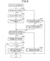
- FIG. 5 is a flowchart of a same-object determination process
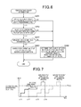
- FIG. 6 is a flowchart of a tentative same-object determination process
- FIG. 7 is an example timing chart of the tentative same-object determination process
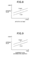
- FIG. 8 is a schematic of maps of first and second determination thresholds versus detected distance.
- FIG. 9 is a schematic of maps of first and second determination thresholds versus confidence-level determination counter N.
- Example embodiments will now be described more fully with reference to the accompanying drawings.
- Example embodiments are provided so that this disclosure will be thorough, and will fully convey the scope to those who are skilled in the art. Numerous specific details are set forth such as examples of specific components to provide a thorough understanding of embodiments of the present disclosure. It will be apparent to those skilled in the art that example embodiments may be embodied in many different forms and that neither should be construed to limit the scope of the disclosure. Identical or equivalent components or components of equal or equivalent action are thereby identified by the same or similar reference numerals.
- An object detection apparatus mounted in a moving object in accordance with one embodiment of the present invention will now be explained with reference to the accompanying drawings.
- the object detection apparatus of the present embodiment is mounted in a vehicle as the moving object and is configured to receive object sensing information from ranging sensors mounted in the vehicle to detect an object around the vehicle, such as another vehicle, a roadway construction or the like.
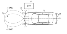
- An object detection system in accordance with the present embodiment will now be explained with reference to FIG. 1 .
- each of ranging sensors 20 may be an ultrasonic sensor having a function of transmitting an ultrasonic wave at a frequency in a range of 20-100 kHz as a probe wave and a function of receiving a reflection of the prove wave from an object.
- four ranging sensors 20 are attached to a front portion of the vehicle 30 (e.g., a front bumper) and spaced apart from each other by a predetermined spacing in a widthwise direction of the vehicle perpendicular to the traveling direction of the vehicle 30 .
- the ranging sensors 20 include two center sensors (first and second sensors 21 , 22 ) in proximity to the center line 31 of the vehicle 30 and at symmetrical positions about the center line 31 , and corner sensors 23 , 24 at front left and right corners of the vehicle 30 .
- Four more ranging sensor 20 are attached to a rear portion of the vehicle 30 (e.g., a rear bumper) at similar positions, therefore including two center sensors and two corner sensors.
- These rear ranging sensors attached to the rear portion of the vehicle 30 have the same functions as the ranging sensors attached to the front portion of the vehicle 30 . Therefore, descriptions for the rear ranging sensors 20 will not be repeated below.
- the ranging sensor has a range of direct object detection 40 such that a reflection of the probe wave transmitted by the ranging sensor from an object within the range of direct object detection can be received by the ranging sensor.
- Any pair of adjacent ranging sensors 20 are attached to the front portion of the vehicle 30 so that the ranges of direct object detection 40 of the adjacent ranging sensors 20 at least partially overlap each other.
- the corner sensors 23 , 24 may also have similar ranges of direct object detection 40 .
- Each of the ranging sensors 20 has a threshold value for amplitude of reflections. Upon receipt of a reflection having an amplitude equal to or greater than the threshold value, the ranging sensor 20 transmits object sensing information including a receipt time of the reflection to an electronic control unit (ECU) 10 as the object detection apparatus of the present embodiment.
- ECU electronice control unit
- the ECU 10 includes a microcomputer formed of CPU and various memories, such as RAM and ROM, and is configured to detect the object(s) 50 around the vehicle 30 based on the object sensing information of the object(s) 50 received from the ranging sensors 20 . More specifically, the ECU 10 transmits control signals to at least one of the ranging sensors 20 every predetermined time interval (e.g., every hundreds of milliseconds) to instruct the ranging sensors 20 to transmit the probe wave. Upon receipt of the object sensing information of the object 50 from the ranging sensors 20 , the ECU 10 determines the presence or absence of the object 50 around the vehicle based on the received sensing information.
- a microcomputer formed of CPU and various memories, such as RAM and ROM
- the ECU 10 When it is determined that the object 50 is present around the vehicle 30 , then the ECU 10 performs a vehicle-object interaction avoidance control, such as a steering angle control or a deceleration control, or notification to a driver of the vehicle 30 using an audible alarm so that the vehicle 30 does not interact with the object 50 .
- a vehicle-object interaction avoidance control such as a steering angle control or a deceleration control
- the ECU 10 transmits transmission instructions to the ranging sensors 20 to cause each of the ranging sensors 20 to transmit an ultrasonic wave as a probe wave in a predefined sequence at predetermined time intervals.
- the first center sensor 21 transmits an ultrasonic wave and then the second center sensor 22 transmits an ultrasonic wave.
- the corner sensor 23 transmits an ultrasonic wave and then the corner sensor 24 transmits an ultrasonic wave.
- the probe waves are sequentially transmitted at predefined time intervals such that the sequentially transmitted probe waves do not interfere with each other.
- the first received reflection at the ranging sensors 20 after the sequential transmissions of the ultrasonic waves from the ranging sensors 21 , 22 , 23 , 24 is valid, and the second to fourth reflections received after receipt or the first received reflection are invalidated.
- the ECU 10 uses the object sensing information of the object 50 received from the ranging sensors 20 to calculate a position (i.e., coordinates) of the object 50 relative to the vehicle 30 (referred to as a relative position of the object 30 ) using the principle of triangulation.
- a position i.e., coordinates
- the coordinates of a measurement point are calculated using a known distance between two points and distances from the two points to the measurement point.
- the ECU 10 calculates the relative position of the object 50 based on a known distance between two adjacent ranging sensors 20 whose ranges of direct object detection 40 at least partially overlap each other and measured distances from the two adjacent ranging sensors 20 to the object 50 .
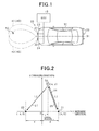
- FIG. 2 is a schematic of calculating the detected relative position of the object 50 , which shows the first and second center sensors 21 , 22 and the object 50 in front of the first and second center sensors 21 , 22 in plan view.
- the first center sensor 21 serves as an active sensor configured to transmit a probe wave 25 and receive a direct wave 26 that is a reflection of the probe wave 25 at a first location
- the second sensor 22 serves as a passive sensor configured to only receive an indirect wave 27 that is a reflection of the probe wave 25 transmitted by the first sensor 21 at a second location away from the first location.
- the ECU 10 calculates an estimated (relative) position of the object 50 specified by X- and Y-coordinates x, y of the object 50 in a coordinate system defined by an X-axis being a straight line passing through the first and second sensors 21 , 22 and a Y-axis being a straight line passing through a median between the first and second sensors 21 , 22 and perpendicular to the X-axis. More specifically, in the present embodiment, the ECU 10 instructs the first center sensor (active sensor) 21 to transmit the probe wave 25 .
- the ECU 10 calculates a distance L 1 between the first center sensor 21 and the object 50 based on the direct wave 26 .
- the ECU 10 calculates a distance L 2 between the second sensor 22 and the object 50 based on the indirect wave 27 .
- a distance between an origin O of the coordinate system at which the X-axis and the Y-axis intersect and the first sensor 21 is equal to a distance between the origin O and the second sensor 22 , which distances are denoted by d and stored beforehand in the ECU 10 .
- the ECU 10 calculates a first time t 1 and a second time t 2 , where the first time t 1 is the time the direct wave 26 is received by the first sensor 21 subtracted by the time the probe wave 25 is transmitted by the first sensor 21 and the second time t 2 is the time the indirect wave 27 is received by the second sensor 22 subtracted by the time the probe wave 25 is transmitted by the first sensor 21 .
- the first time t 1 multiplied by the speed of sound is twice the distance L 1 between the first sensor 21 and the object 50 .
- the second time t 2 multiplied by the speed of sound is a sum of the distance L 1 between the first sensor 21 and the object 50 and a distance L 2 between the second sensor 22 and the object 50 .
- the ECU 10 performs a triangulation calculation using the distance 2 d between the first center sensor 21 and the second center sensor 22 and the first time t 1 and the second time t 2 to calculate the coordinates (x, y) of the object 50 .
- FIG. 2 shows an example where the first center sensor 21 serves as an active sensor and the second center sensor 22 serves as a passive sensor.
- coordinates of an object 50 can be calculated using any combination of adjacent sensors 21 - 24 in a similar manner based on the principle of triangulation.
- coordinates of an object 50 rearward of the vehicle 30 can be calculated using any combination of adjacent sensors attached to the rear portion of the vehicle 30 in a similar manner.
- the ECU 10 sets, as an indication of the likelihood of the object being actually present, a confidence-level determination counter N (as a degree of confidence) for each of the ranging sensors 20 based on the number of times the same object has been detected. For each of the ranging sensors 20 , the confidence-level determination counter N is incremented or decremented such that as the number of times the same object has been detected by the ranging sensor increases, the confidence-level determination counter N is increased. When the confidence-level determination counter N exceeds a threshold, it is determined that the object detected by the ranging sensor is actually present around the vehicle 30 , so that intervention of the interaction avoidance control is permitted. If it is determined that the object detected in the previous cycle and the object detected in the current cycle are different, the confidence-level determination counter N is reset.
- a same-object determination process is performed, in which it is determined whether or not objects detected by a respective one of the ranging sensors 20 in the current and previous cycles are the same. If it is determined that objects detected by one of the ranging sensors 20 in the current and previous cycles are the same, the value of the confidence-level determination counter N is incremented. More specifically, based on a history of positions of the objects detected in the previous cycles, an object position in the next cycle is predicted. Thereafter, the predicted object position and the object position calculated by the triangulation in the current cycle are compared.
- the object position calculated by the triangulation in the current cycle is within a first range of determination including therein the predicted object position, it is determined that the object at the object position calculated by the triangulation in the current cycle and the object position calculated by the triangulation in the previous cycle are the same. Then the value of the confidence-level determination counter N is incremented by a predetermined value. If the value of the confidence-level determination counter N exceeds a predefined threshold after it is consecutively determined plural times that the object at the object position calculated by the triangulation in the current cycle and the object position calculated by the triangulation in the previous cycle are the same, intervention of the vehicle-object interaction avoidance control is permitted.
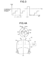
- FIG. 3 shows an example of a temporal development of the confidence-level determination counter N.
- each ranging sensor has a respective confidence-level determination counter N.
- FIG. 3 shows an example of the temporal development of the confidence-level determination counter for one of the four ranging sensors 20 (e.g., the first center sensor 21 ).
- the confidence-level determination counter N is incremented (at times t 11 , t 12 ). If the object position calculated by the triangulation in the current cycle is out of the first range of determination, then it is determined, in principle, that the object detected in the previous cycle and the object detected in the current cycle are different objects or not the same. Then, as shown in FIG. 3 , the confidence-level determination counter N is rest (at time t 13 ). If the value of the confidence-level determination counter N exceeds a counter threshold ThA (at time t 14 ) after detecting other objects detected in consecutive cycles that are determined to be the same, the intervention of the vehicle-object interaction avoidance control is permitted.
- ThA at time t 14
- the reflections of ultrasound waves of the ranging sensors 20 may vary with object shapes and environments around the vehicle, which may cause the ranging sensors 20 to detect an object at an incorrect position (i.e., at a position where the detected object is not actually present).
- a large deviation between the object position predicted based on the history of the object positions detected in the previous cycles (i.e., the object position at which the object detected in the previous cycle is expected to be present in the current cycle) and the object position calculated in the current cycle, which may be caused by temporary detection errors, may lead to an incorrect determination that the object detected in the previous cycle and the object detected in the current cycle are not the same, and then the confidence-level determination counter N is reset. This may delay the intervention of the vehicle-object interaction avoidance control.
- a tentative same-object determination process is performed, in which it is determined whether or not the object detected in the previous cycle and the object detected in the current cycle are likely to be the same. If, in the tentative same-object determination process, it is determined that the object detected in the previous cycle and the object detected in the current cycle are likely to be the same, determining that the object detected in the previous cycle and the object detected in the current cycle are different objects is suspended.
- the object position calculated by the triangulation in the current cycle is within a second range of determination surrounding the first range of determination. If it is determined that the object position calculated in the current cycle is out of the second range of determination, then it is determined that the object detected in the previous cycle and the object detected in the current cycle are different objects. If it is determined that the object position calculated in the current cycle is within the second range of determination (but out of the first range of determination), then determining that the object detected in the previous cycle and the object detected in the current cycle are different objects is suspended.
- FIG. 4A shows a schematic of the tentative same-object determination process.
- the first determination range is a circular region P having a radius of a first threshold ThB 1 and centered at the predicted position 51
- the second determination range is an annular region Q having an inner radius of the first threshold ThB 1 and an outer radius of a second threshold ThB 2 (where ThB 2 >ThB 1 ) and centered at the predicted position 51 .
- the predicted position 51 and three detected object positions 52 - 54 are shown. If the object detected in the current cycle is at the position 52 that is within the first range of determination P, it is determined that the object detected in the previous cycle and the object detected in the current cycle are the same.
- the object detected in the current cycle is at the position 54 that is outside the first and second ranges of determination P, Q, then it is determined that the object detected in the previous cycle and the object detected in the current cycle are different objects. If the object detected in the current cycle is at the position 53 that is outside the first range of determination P, but within the second range of determination Q, then determining that the object detected in the previous cycle and the object detected in the current cycle are different objects is suspended (or forgone) and carried over to the subsequent cycles unless the degree of confidence of the object detected in the previous cycle is equal to or greater than a predetermined value.
- boundaries of the first and second ranges of determination P, Q are concentric circles centered at the predicted position 51 .
- boundaries of the first and second ranges of determination P, Q may be ovals centered at the predicted position 51 that are long in the widthwise direction, which may be more advantageous because the detection errors of the ranging sensors 20 in the widthwise direction of the vehicle 30 are greater than the detection errors of the ranging sensors 20 in the traveling direction.
- FIG. 5 shows a flowchart of the same-object determination process in accordance with the present embodiment. This process is performed in the ECU 10 repeatedly every predetermined time interval.
- step S 101 it is determined whether or not the triangulation is feasible. For example, it is determined that the triangulation is feasible only if the direct wave 26 and the indirect wave 27 have been received during a predetermined wait period after transmission of the probe wave 25 from the ranging sensor 21 .
- the predetermined wait period may be set to, for example, tens of milliseconds. If in step S 101 it is determined whether or not the triangulation is feasible, then the process proceeds to step S 102 , where based on information about the received direct and indirect waves 26 , 27 , coordinates (x, y) specifying an object position are calculated according to the principle of triangulation in a manner as described with reference to FIG. 2 .
- the predicted object position (i.e., the object position at which the object detected in the previous cycle is expected to be present in the current cycle) is acquired.
- a predicted position of the object 50 (see FIG. 1 ) is calculated based on the history of detected object positions calculated by the triangulation in the previous cycles.
- the predicted position of the object 50 (as a coordinate point) is calculated using parameters including coordinates of the objects detected, for example, in the previous cycle and the before the previous cycle, and a speed of the object 50 relative to the vehicle 30 (i.e., the relative speed of the object 50 ).
- step S 104 it is determined whether or not the object detected in the previous cycle and the object detected in the current cycle are the same. More specifically, it is determined whether or not the object position detected in the current cycle is within the first range of determination P. In the present embodiment, only if all the following conditions ( 1 - 1 ) to ( 1 - 4 ) are met, it is determined that the object position detected in the current cycle is within the first range of determination P.
- the condition ( 1 - 1 ) is that a difference between the x-coordinate of the predicted object position 51 and the x-coordinate of the detected objected position (i.e., the object position detected in the current cycle) is less than a first x-coordinate determination threshold ThB 1 x .
- the condition ( 1 - 2 ) is that a difference between the y-coordinate of the predicted object position 51 and the y-coordinate of the detected objected position is less than a first y-coordinate determination threshold ThB 1 y .
- the condition ( 1 - 3 ) is that a difference between the distance from the active sensor 21 to the predicted object position 51 and the detected distance calculated based on the direct wave 26 is less than a first direct-wave determination threshold ThB 1 a .
- the condition ( 1 - 4 ) is that a difference between the distance from the passive sensor 22 to the predicted object position 51 and the detected distance calculated based on the indirect wave 27 is less than a first indirect-wave determination threshold ThB 1 b.
- step S 104 If all the conditions ( 1 - 1 ) to ( 1 - 4 ) are met, it is determined in step S 104 that the object detected in the previous cycle and the object detected in the current cycle are the same. Thereafter, the process proceeds to step S 105 , where the confidence-level determination counter N is incremented. Subsequently, in step S 106 , it is determined whether or not the confidence-level determination counter N has exceeded the counter threshold ThA. If N ⁇ ThA, then the process ends. If N>ThA, then the process proceeds to step S 107 , where the intervention of the vehicle-object interaction avoidance control is permitted.
- step S 101 determines whether the triangulation is infeasible. If in step S 101 it is determined that the triangulation is infeasible, the process proceeds to step S 109 , where it is determined whether or not only either one of the direct wave 26 and the indirect wave 27 has been received. If in step S 109 it is determined whether or not none of the direct wave 26 and the indirect wave 27 have been received during the predetermined wait period after transmission of the probe wave 25 from the ranging sensor 21 , then the process ends.
- step S 109 If in step S 109 it is determined that only either one of the direct wave 26 and the indirect wave 27 has been received during the predetermined wait period after transmission of the probe wave 25 from the ranging sensor 21 , then the process proceeds to step S 110 .
- step S 110 a distance from the active sensor 21 to the predicted object position and a distance detected based on the reflection (the direct wave 26 or the indirect wave 27 ) are calculated. Thereafter, the process proceeds to step S 104 , where it is determined whether or not the object detected in the previous cycle and the object detected in the current cycle are the same.
- step S 104 it is determined whether or not either one of the conditions ( 1 - 3 ) and ( 1 - 4 ), among the conditions ( 1 - 1 ) to ( 1 - 4 ), is met. If in step S 104 it is determined that either one of the conditions ( 1 - 3 ) and ( 1 - 4 ) is met, the process proceeds to step S 105 .
- step S 104 if the object position detected in the current cycle is out of the first range of determination P and thus it is determined in step S 104 that the object detected in the previous cycle and the object detected in the current cycle are not the same, the process proceeds to step S 108 , where the tentative same-object determination process as shown in FIG. 6 is performed.
- step S 201 it is determined whether or not the confidence level of the object detected in the previous cycle is at or above a predetermined level. More specifically, the determination in step S 201 is made by reading a previous value of the confidence-level determination counter N and then comparing the previous value of the confidence-level determination counter N and a criterion value. If it is determined that the previous value of the confidence-level determination counter N is equal to or greater than the criterion value, then the process proceeds to step S 203 , where it is determined whether or not the object detected in the previous cycle and the object detected in the current cycle are likely to be the same.
- step S 203 it is determined whether or not the object position detected in the current cycle is within the second range of determination Q.
- the triangulation is feasible, it is determined that the object position detected in the current cycle is within the second range of determination Q only if all the following conditions ( 2 - 1 ) to ( 2 - 4 ) are met. If the triangulation is infeasible and if only either one of the direct wave 26 and the indirect wave 27 has been received, it is determined that the object position detected in the current cycle is within the second range of determination Q if it is determined that either one of the conditions ( 1 - 3 ) and ( 1 - 4 ) is met.
- the condition ( 2 - 1 ) is that a difference between the x-coordinate of the predicted object position 51 and the x-coordinate of the detected objected position (i.e., the object position detected in the current cycle) is less than a second x-coordinate determination threshold ThB 2 x such that ThB 2 x >ThB 1 x .
- the condition ( 2 - 2 ) is that a difference between the y-coordinate of the predicted object position 51 and the y-coordinate of the detected objected position is less than a second y-coordinate determination threshold ThB 2 y such that ThB 2 y >ThB 1 y .
- the condition ( 2 - 3 ) is that a difference between the distance from the active sensor 21 to the predicted object position 51 and the distance detected based on the direct wave 26 is less than a second direct-wave determination threshold ThB 2 a such that ThB 2 a >ThB 1 a .
- the condition ( 2 - 4 ) is that a difference between the distance from the passive sensor 22 to the predicted object position 51 and the distance detected based on the indirect wave 27 is less than a second indirect-wave determination threshold ThB 2 b such that ThB 2 b >ThB 1 b.
- step S 203 If in step S 203 it is determined that the object detected in the previous cycle and the object detected in the current cycle are likely to be the same, then the process proceeds to step S 204 , where it is determined whether or not the number of tentative same-object determinations is less than a predetermined value Mth, where the number of tentative same-object determinations refers to the number of times of consecutively determining in step S 203 that the object detected in the previous cycle and the object detected in the current cycle are likely to be the same. If in step S 204 it is determined that the number of tentative same-object determinations is less than the predetermined value Mth, then the process proceeds to step S 205 , where the value of the confidence-level determination counter N is carried over to the next cycle.
- step S 201 If in step S 201 it is determined that the object confidence level in the previous cycle is below the predetermined level, or if in step S 203 it is determined that the object detected in the previous cycle and the object detected in the current cycle are less likely to be the same, or if in step S 204 it is determined that the number of tentative same-object determinations is equal to or greater than the predetermined value Mth, then the process proceeds to step S 202 , where it is determined that the object detected in the previous cycle and the object detected in the current cycle are different objects. Thereafter, the confidence-level determination counter N is reset.
- the solid line indicates a temporal development of the confidence-level determination counter N for one of the four ranging sensors 20 (e.g., the first center sensor 21 ) with the tentative same-object determination process to be performed
- the broken line indicates a temporal development of the confidence-level determination counter N without the tentative same-object determination process.
- the object position detected in the current cycle is within the first range of determination P with a small deviation between the predicted object position and the detected object position, it is determined that the object detected in the previous cycle and the object detected in the current cycle are the same and the confidence-level determination counter N is incremented (at and after t 21 ). If the detected object position gets out of the first range of determination P (at t 22 ) and then if the confidence-level determination counter N is equal to or greater than the predetermined value, the tentative same-object determination process is performed.
- the detected object position is within the second range of determination Q, determining that the object detected in the previous cycle and the object detected in the current cycle are different objects is suspended and the value of the confidence-level determination counter N is left unchanged. If at time t 23 it is determined that the object position detected in the current cycle is within the first range of determination P, incrementing of a same-object determination counter K is resumed. Thereafter, if the confidence-level determination counter N exceeds the counter threshold ThA, the intervention of the vehicle-object interaction avoidance control is permitted (at t 24 ).
- the confidence-level determination counter N is reset at time t 22 where it is determined that the object position detected in the current cycle is out of the first range of determination P. Accordingly, permitting the intervention of the vehicle-object interaction avoidance control will be delayed as compared with a configuration where the tentative same-object determination process is performed.
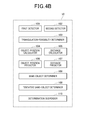
- FIG. 4B shows a functional block diagram of the ECU 10 that corresponds to the object detection apparatus of the present embodiment.
- the ECU 10 includes a first detector 101 , a second detector 102 , an object-position calculator 104 , a same-object determiner 108 , a tentative same-object determiner 109 , a determination suspender 110 , an object-position predictor 106 , a triangulation-feasibility determiner 103 , a distance calculator 105 , a distance predictor 107 .
- Functions of these functional blocks may be implemented by the CPU executing various programs stored in the ROM or the like.
- the first detector 101 is configured to detect the object based on the direct wave 26 that is a first reflection of the probe wave 25 from the object 50 , where the probe wave 25 and the first reflection 26 are respectively transmitted and received by the same ranging sensor that is a first ranging sensor 21 that is one of the plurality of ranging sensors 20 .
- the second detector 102 is configured to detect the object based on the indirect wave 27 that is a second reflection of the probe wave 25 from the object 50 , where the second reflection is received by a second ranging sensor 22 that is another one of the plurality of ranging sensors 20 .
- the object-position calculator 104 is responsible for execution of step S 102 based on the detections of the first and second detectors 101 , 102 .
- the same-object determiner 108 is responsible for execution of step S 104
- the tentative same-object determiner 109 is responsible for execution of steps S 203 -S 204
- the determination suspender 110 responsible for execution of step S 205 .
- the object-position predictor 106 is responsible for execution of step S 103
- the triangulation-feasibility determiner 103 is responsible for execution of step S 101
- the distance calculator 105 is responsible for execution of step S 110
- the distance predictor 107 is responsible for execution of step S 110 .
- the above process has been described as being performed based on the detections of the ranging sensors 21 , 22 . Practically, the above process is performed for each combination of adjacent sensors (active and passive sensors) among the ranging sensors 21 - 24 .
- the object detection apparatus of the present embodiment configured as above can provide the following advantages.
- the tentative same-object determination process is performed without immediately determining that the object detected in the previous cycle and the object detected in the current cycle are different objects.
- the tentative same-object determination process it is determined whether or not the object detected in the previous cycle and the object detected in the current cycle are likely to be the same, on the condition that the object detected in the previous cycle has a predetermined or higher degree of confidence.
- the object position detected in the current cycle is out of the first range of determination P centered at the predicted object position and then if the object detected in the previous cycle has a predetermined or higher degree of confidence, it is determined whether or not the object position detected in the current cycle is within the second range of determination Q. If is determined that the object detected in the previous cycle and the object detected in the current cycle are likely to be the same, then determining that the object detected in the previous cycle and the object detected in the current cycle are different objects is suspended.
- the object detected in the previous cycle having a high degree of confidence is likely to be present in the current cycle, and transient detection errors may have occurred in detecting the object.
- An incorrect same-object determination caused by the transient errors that the object detected in the previous cycle and the object detected in the current cycle are different objects may lead to wastage of sensing information that has been accumulated in the current and previous cycles and may delay the intervention of the vehicle-object interaction avoidance control, which may prevent the vehicle-object interaction avoidance control from being properly performed. Addressing this concern, with the above configuration, even in the presence of transient detection errors, an incorrect same-object determination caused by the transient detection errors can be avoided.
- the tentative same-object determination process determining that that the object detected in the previous cycle and the object detected in the current cycle are different objects is suspended, on the condition that the number of times of consecutively determining that the object detected in the previous cycle and the object detected in the current cycle are likely to be the same is less than the predetermined number of times.
- the object detected in the previous cycle and the object detected in the current cycle are likely to be different objects. Addressing this concern, with the configuration as described above, it can be accurately determined whether or not the object detected in the previous cycle and the object detected in the current cycle are the same.
- the triangulation is infeasible in the current cycle, it is determined based on the comparison of the distance to the predicted object position (referred to as a predicted distance) and the distance to the object detected in the current cycle whether or not the object detected in the previous cycle and the object detected in the current cycle are the same, and further in the tentative same-object determination process it is determined whether or not the object detected in the previous cycle and the object detected in the current cycle are likely to be the same.
- the same-object determination is made based on the distance information about the predicted distance and the distance to the detected object, which allows it to be rapidly determined that an object is present around the vehicle.
- the ultrasonic sensors have a small detection error in the traveling direction of the vehicle while having a large calculation error in the widthwise direction of the vehicle, which can probably lead to an incorrect calculated object position. Therefore, the object detection system configured as above having the ultrasonic sensors as the ranging sensors 20 can prevent the same-object determination (i.e., determining that the object detected in the previous cycle and the object detected in the current cycle are the same) from being made based on the incorrect positional information. This allows the same-object determination to be made accurately.
- the first and second ranges of determination are fixed.
- at least one of the first and second ranges of determination may be variably set.
- at least one of the first and second ranges of determination may be variably set based on the detected distance to the object. This is because the reflections from the object are weakened with increasing detected distance to the object, which may lead to a larger calculation error of the object position.
- the first determination threshold ThB 1 in the conditions ( 1 - 1 ) to ( 1 - 4 ) and the second determination threshold ThB 2 in the conditions ( 2 - 1 ) to ( 2 - 4 ) may be increased with increasing detected distance to the object.
- the first and second ranges of determination are fixed.
- at least one of the first and second ranged of determination may be variably set such that it is less prone to be determined that the object detected in the previous cycle and the object detected in the current cycle are different objects as the confidence level of the object detected in the previous cycle increases. More specifically, as shown in FIG. 9 , the first determination threshold ThB 1 in the conditions ( 1 - 1 ) to ( 1 - 4 ) and the second determination threshold ThB 2 in the conditions ( 2 - 1 ) to ( 2 - 4 ) may be increased with increasing value of the confidence-level determination counter N in the previous cycle.
- the first and second ranges of determination are fixed.
- at least one of the first and second ranges of determination may be variably set based on the detected distance to the object and the confidence level of the object detected in the previous cycle.
- both the first determination threshold ThB 1 in the conditions ( 1 - 1 ) to ( 1 - 4 ) and the second determination threshold ThB 2 in the conditions ( 2 - 1 ) to ( 2 - 4 ) may be variably set based on the detected distance to the object and the confidence level of the object detected in the previous cycle.
- the first determination threshold ThB 1 in the conditions ( 1 - 1 ) to ( 1 - 4 ) may be variably set using the maps of FIGS. 8 and 9 , based on the detected distance to the object and the confidence level of the object detected in the previous cycle, and the second determination threshold ThB 2 may be variably set using the maps of FIG. 8 , based on the detected distance to the object.
- the first and second ranges of determination are fixed.
- at least one of the first and second ranges of determination may be variably set based on parameters of an ambient environment around the vehicle 30 .
- the reflections of the ultrasonic waves transmitted by the ranging sensors 20 are varied with the outside air temperature, the humidity, the wind strength or the like, which may lead to accordingly different calculation errors of the object position. More specifically, the reflections are prone to weaken with increasing outside air temperature, the reflections are prone to weaken with increasing humidity, and the reflections are prone to weaken with increasing wind strength. Accordingly, the calculation error of the object position is prone to increase. Addressing this concern, with the configuration as described above, it can be more accurately determined whether or not the object detected in the previous cycle and the object detected in the current cycle are the same.
- the ranging sensors 20 are attached to the front and rear portions of the vehicle 30 to detect an object around the vehicle 30 .
- the ranging sensors 20 may be attached to the right- and left-side surface portions of the vehicle 30 to detect an object around the vehicle 30 .
- the ranging sensors 20 are ultrasonic sensors adapted to use an ultrasonic wave as a probe wave to detect an object.
- the ranging sensors 20 may be any other sensors capable of transmitting a probe wave and receive a reflection of the probe wave to thereby detect an object.
- the ranging sensors 20 may include millimeter-wave radar or laser radar or the like adapted to use an electromagnetic wave to detect an object.
- the object detection apparatus is mounted in the vehicle.
- the object detection apparatus may be mounted in a moving object other than the vehicle, such as an airplane, a ship, a robot or the like.
Landscapes
- Engineering & Computer Science (AREA)
- Physics & Mathematics (AREA)
- Theoretical Computer Science (AREA)
- General Physics & Mathematics (AREA)
- Radar, Positioning & Navigation (AREA)
- Multimedia (AREA)
- Remote Sensing (AREA)
- Data Mining & Analysis (AREA)
- Computer Vision & Pattern Recognition (AREA)
- Quality & Reliability (AREA)
- General Engineering & Computer Science (AREA)
- Evolutionary Biology (AREA)
- Evolutionary Computation (AREA)
- Bioinformatics & Computational Biology (AREA)
- Bioinformatics & Cheminformatics (AREA)
- Artificial Intelligence (AREA)
- Life Sciences & Earth Sciences (AREA)
- Computer Networks & Wireless Communication (AREA)
- Acoustics & Sound (AREA)
- Measurement Of Velocity Or Position Using Acoustic Or Ultrasonic Waves (AREA)
- Traffic Control Systems (AREA)
Abstract
Description
- This application is based on and claims the benefit of priority from earlier Japanese Patent Application No. 2014-215092 filed Oct. 22, 2014, the description of which is incorporated herein by reference.
- 1. Technical Field
- The present invention relates to an object detection apparatus for detecting an object around a vehicle carrying the apparatus.
- 2. Related Art
- Conventionally, a known object detection apparatus, as disclosed in Japanese Patent Application Laid-Open Publication No. 2014-89077, includes at least one ranging sensor, such as an ultrasonic sensor or the like, mounted in a vehicle to detect an object, such as a pedestrian, an obstacle or the like, around the vehicle, and based on detection results, performs various types of control, such as actuation of a braking device and notification to a driver, for improving vehicle driving safety.
- The object detection apparatus disclosed in Japanese Patent Application Laid-Open Publication No. 2014-89077 includes a plurality of ranging sensors mounted in the vehicle to calculate a widthwise position of the object based on the principle of triangulation, where the widthwise position of the object refers to a position of the object in a widthwise or cross vehicle direction perpendicular to a traveling direction of the vehicle. If the widthwise position of the object is within the vehicle width, it is determined that the object has been detected. If the widthwise position of the object is not within the vehicle width, it is determined that the object has not been detected. Performing such a determination process can prevent erroneously detecting an object that is actually less likely to contact the vehicle as an object that is likely to contact the vehicle.
- When an object is detected using the ranging sensors, reflections of ultrasound waves of the ranging sensors may vary with object shapes and environments around the vehicle. Variations of the reflections may cause variations in detected position of the object. Therefore, despite that actually the same object has been detected, it may be determined that another object has been detected, or despite that actually another object (than the object of interest) has been detected, it may be determined that the same object has been detected. There is concern that such incorrect determinations may cause intervention of control for improving the vehicle driving safety to be permitted despite that the intervention of such control being unnecessary, or to be missed despite the intervention of such control being necessary.
- In consideration of the foregoing, exemplary embodiments of the present invention are directed to providing an object detection apparatus capable of avoiding determining the identity of an object based on incorrect position information.
- In accordance with an exemplary embodiment of the present invention, there is provided an object detection apparatus for detecting an object around a moving object with a plurality of ranging sensors attached to the moving object by transmitting a probe wave and receiving reflections of the probe wave from the object via the plurality of ranging sensor. The apparatus includes: a first detector configured to detect the object based on a direct wave that is a first reflection of the probe wave from the object, the probe wave and the first reflection being respectively transmitted and received by the same ranging sensor that is a first ranging sensor that is one of the plurality of ranging sensors; a second detector configured to detect the object based on an indirect wave that is a second reflection of the probe wave from the object, the second reflection being received by a second ranging sensor that is another one of the plurality of ranging sensors; an object-position calculator configured to calculate an object position as a position of the object based on the detections of the first and second detectors according to the principle of triangulation; a same-object determiner configured to, based on the object position calculated by the object-position calculator in the previous cycle and the object position calculated by the object-position calculator in the current cycle, determine whether or not the object detected by the first and second detectors in the previous cycle and the object detected by the first and second detectors in the current cycle are the same; a tentative same-object determiner configured to, if it is determined by the same-object determiner that the object detected by the first and second detectors in the previous cycle and the object detected by the first and second detectors in the current cycle are not the same and if a degree of confidence of the object detected by the first and second detectors in the previous cycle is equal to or greater than a predetermined degree, determine whether or not the object detected by the first and second detectors in the previous cycle and the object detected by the first and second detectors in the current cycle are likely to be the same; and a determination suspender configured to, if it is determined by the tentative same-object determiner that the object detected by the first and second detectors in the previous cycle and the object detected by the first and second detectors in the current cycle are likely to be the same, suspend determining that the object detected by the first and second detectors in the previous cycle and the object detected by the first and second detectors in the current cycle are not the same.
- In the above embodiment, if, based on information about the object position detected by the sensors in the previous cycle and the object position detected by the sensors in the current cycle, it is determined that the object detected in the previous cycle and the object detected in the current cycle are not the same, then the tentative same-object determination process is performed, where it is determined whether or not the object detected in the previous cycle and the object detected in the current cycle are likely to be the same, provided the object detected in the previous cycle has a predetermined or higher degree of confidence. More specifically, if it is determined that the object position detected in the current cycle is out of the first range of determination including and catered at the predicted object position, it is determined whether or not the object position detected in the current cycle is within the second range of determination, provided the object detected in the previous cycle has a predetermined or higher degree of confidence. If it is determined that the object detected in the previous cycle and the object detected in the current cycle are likely to be the same, then it is suspended determining that the object detected in the previous cycle and the object detected in the current cycle are different objects.
- When an object is detected using the ranging sensors, reflections of prove waves, such as ultrasonic waves, of the ranging sensors from the object may vary with object shapes and the environment around the vehicle. Variations of the reflections may cause variations in detected position of the object leading to transient detection errors of the object position. Therefore, the determination that the object detected in the previous cycle and the object detected in the current cycle are not the same may be caused by such transient detection errors. Such a determination that the object in the previous cycle and the object in the current cycle are not the same may cause intervention of control for improving the vehicle driving safety to be permitted at undesired timings. With the above configuration, in cases where the object detected in the previous cycle has a high degree of confidence and it is likely that the transient detection errors are likely to have occurred, the tentative same-object determination process is performed. If in the tentative same-object determination process it is determined that the object detected in the previous cycle and the object detected in the current cycle are likely to be the same, determining that the object detected in the previous cycle and the object detected in the current cycle are different objects is suspended. Therefore, even if an incorrect object position is calculated, this can avoid a same-object determination based on the incorrect calculated object.
-
FIG. 1 is a schematic of an object detection system in accordance with one embodiment of the present invention; -
FIG. 2 is a schematic of calculating a position of an object by triangulation; -
FIG. 3 is an example timing chart of a temporal development of a confidence-level determination counter N; -
FIG. 4A is a schematic of a tentative same-object determination process; -
FIG. 4B is a functional block diagram of an electronic control unit of the object detection system; -
FIG. 5 is a flowchart of a same-object determination process; -
FIG. 6 is a flowchart of a tentative same-object determination process; -
FIG. 7 is an example timing chart of the tentative same-object determination process; -
FIG. 8 is a schematic of maps of first and second determination thresholds versus detected distance; and -
FIG. 9 is a schematic of maps of first and second determination thresholds versus confidence-level determination counter N. - Example embodiments will now be described more fully with reference to the accompanying drawings. Example embodiments are provided so that this disclosure will be thorough, and will fully convey the scope to those who are skilled in the art. Numerous specific details are set forth such as examples of specific components to provide a thorough understanding of embodiments of the present disclosure. It will be apparent to those skilled in the art that example embodiments may be embodied in many different forms and that neither should be construed to limit the scope of the disclosure. Identical or equivalent components or components of equal or equivalent action are thereby identified by the same or similar reference numerals. An object detection apparatus mounted in a moving object in accordance with one embodiment of the present invention will now be explained with reference to the accompanying drawings. The object detection apparatus of the present embodiment is mounted in a vehicle as the moving object and is configured to receive object sensing information from ranging sensors mounted in the vehicle to detect an object around the vehicle, such as another vehicle, a roadway construction or the like. An object detection system in accordance with the present embodiment will now be explained with reference to
FIG. 1 . - Referring to
FIG. 1 , each of rangingsensors 20 may be an ultrasonic sensor having a function of transmitting an ultrasonic wave at a frequency in a range of 20-100 kHz as a probe wave and a function of receiving a reflection of the prove wave from an object. In the present embodiment, four rangingsensors 20 are attached to a front portion of the vehicle 30 (e.g., a front bumper) and spaced apart from each other by a predetermined spacing in a widthwise direction of the vehicle perpendicular to the traveling direction of thevehicle 30. More specifically, the rangingsensors 20 include two center sensors (first andsecond sensors 21, 22) in proximity to thecenter line 31 of thevehicle 30 and at symmetrical positions about thecenter line 31, andcorner sensors vehicle 30. Four more rangingsensor 20 are attached to a rear portion of the vehicle 30 (e.g., a rear bumper) at similar positions, therefore including two center sensors and two corner sensors. These rear ranging sensors attached to the rear portion of thevehicle 30 have the same functions as the ranging sensors attached to the front portion of thevehicle 30. Therefore, descriptions for therear ranging sensors 20 will not be repeated below. - For each of the ranging
sensors 20, the ranging sensor has a range ofdirect object detection 40 such that a reflection of the probe wave transmitted by the ranging sensor from an object within the range of direct object detection can be received by the ranging sensor. Any pair of adjacent rangingsensors 20 are attached to the front portion of thevehicle 30 so that the ranges ofdirect object detection 40 of the adjacent rangingsensors 20 at least partially overlap each other. Although only the ranges ofdirect object detection FIG. 1 , thecorner sensors direct object detection 40. Each of the rangingsensors 20 has a threshold value for amplitude of reflections. Upon receipt of a reflection having an amplitude equal to or greater than the threshold value, the rangingsensor 20 transmits object sensing information including a receipt time of the reflection to an electronic control unit (ECU) 10 as the object detection apparatus of the present embodiment. - The ECU 10 includes a microcomputer formed of CPU and various memories, such as RAM and ROM, and is configured to detect the object(s) 50 around the
vehicle 30 based on the object sensing information of the object(s) 50 received from the rangingsensors 20. More specifically, theECU 10 transmits control signals to at least one of the rangingsensors 20 every predetermined time interval (e.g., every hundreds of milliseconds) to instruct the rangingsensors 20 to transmit the probe wave. Upon receipt of the object sensing information of theobject 50 from the rangingsensors 20, theECU 10 determines the presence or absence of theobject 50 around the vehicle based on the received sensing information. When it is determined that theobject 50 is present around thevehicle 30, then theECU 10 performs a vehicle-object interaction avoidance control, such as a steering angle control or a deceleration control, or notification to a driver of thevehicle 30 using an audible alarm so that thevehicle 30 does not interact with theobject 50. - The
ECU 10 transmits transmission instructions to the rangingsensors 20 to cause each of the rangingsensors 20 to transmit an ultrasonic wave as a probe wave in a predefined sequence at predetermined time intervals. In the present embodiment, in response to the transmission instructions from theECU 10, thefirst center sensor 21 transmits an ultrasonic wave and then thesecond center sensor 22 transmits an ultrasonic wave. Subsequently, thecorner sensor 23 transmits an ultrasonic wave and then thecorner sensor 24 transmits an ultrasonic wave. The probe waves are sequentially transmitted at predefined time intervals such that the sequentially transmitted probe waves do not interfere with each other. In addition, in the present embodiment, only the first received reflection at the rangingsensors 20 after the sequential transmissions of the ultrasonic waves from the rangingsensors - The
ECU 10 uses the object sensing information of theobject 50 received from the rangingsensors 20 to calculate a position (i.e., coordinates) of theobject 50 relative to the vehicle 30 (referred to as a relative position of the object 30) using the principle of triangulation. According to the well-known principle of triangulation, the coordinates of a measurement point are calculated using a known distance between two points and distances from the two points to the measurement point. According to such principle of triangulation, theECU 10 calculates the relative position of theobject 50 based on a known distance between two adjacent rangingsensors 20 whose ranges ofdirect object detection 40 at least partially overlap each other and measured distances from the two adjacent rangingsensors 20 to theobject 50. -
FIG. 2 is a schematic of calculating the detected relative position of theobject 50, which shows the first andsecond center sensors object 50 in front of the first andsecond center sensors FIG. 2 , thefirst center sensor 21 serves as an active sensor configured to transmit aprobe wave 25 and receive adirect wave 26 that is a reflection of theprobe wave 25 at a first location, and thesecond sensor 22 serves as a passive sensor configured to only receive anindirect wave 27 that is a reflection of theprobe wave 25 transmitted by thefirst sensor 21 at a second location away from the first location. - The
ECU 10 calculates an estimated (relative) position of theobject 50 specified by X- and Y-coordinates x, y of theobject 50 in a coordinate system defined by an X-axis being a straight line passing through the first andsecond sensors second sensors ECU 10 instructs the first center sensor (active sensor) 21 to transmit theprobe wave 25. When thefirst center sensor 21 receives thedirect wave 26 that is a reflection of theprobe wave 25 from theobject 50, theECU 10 calculates a distance L1 between thefirst center sensor 21 and theobject 50 based on thedirect wave 26. When the second center sensor (passive sensor) 22 receives theindirect wave 27 that is a reflection of theprobe wave 25 from theobject 50, theECU 10 calculates a distance L2 between thesecond sensor 22 and theobject 50 based on theindirect wave 27. - A distance between an origin O of the coordinate system at which the X-axis and the Y-axis intersect and the
first sensor 21 is equal to a distance between the origin O and thesecond sensor 22, which distances are denoted by d and stored beforehand in theECU 10. TheECU 10 calculates a first time t1 and a second time t2, where the first time t1 is the time thedirect wave 26 is received by thefirst sensor 21 subtracted by the time theprobe wave 25 is transmitted by thefirst sensor 21 and the second time t2 is the time theindirect wave 27 is received by thesecond sensor 22 subtracted by the time theprobe wave 25 is transmitted by thefirst sensor 21. The first time t1 multiplied by the speed of sound is twice the distance L1 between thefirst sensor 21 and theobject 50. The second time t2 multiplied by the speed of sound is a sum of the distance L1 between thefirst sensor 21 and theobject 50 and a distance L2 between thesecond sensor 22 and theobject 50. TheECU 10 performs a triangulation calculation using the distance 2 d between thefirst center sensor 21 and thesecond center sensor 22 and the first time t1 and the second time t2 to calculate the coordinates (x, y) of theobject 50. - In the present embodiment,
FIG. 2 shows an example where thefirst center sensor 21 serves as an active sensor and thesecond center sensor 22 serves as a passive sensor. Practically, coordinates of anobject 50 can be calculated using any combination of adjacent sensors 21-24 in a similar manner based on the principle of triangulation. As for the ranging sensors attached to the rear portion of thevehicle 30, coordinates of anobject 50 rearward of thevehicle 30 can be calculated using any combination of adjacent sensors attached to the rear portion of thevehicle 30 in a similar manner. - In the present embodiment, the
ECU 10 sets, as an indication of the likelihood of the object being actually present, a confidence-level determination counter N (as a degree of confidence) for each of the rangingsensors 20 based on the number of times the same object has been detected. For each of the rangingsensors 20, the confidence-level determination counter N is incremented or decremented such that as the number of times the same object has been detected by the ranging sensor increases, the confidence-level determination counter N is increased. When the confidence-level determination counter N exceeds a threshold, it is determined that the object detected by the ranging sensor is actually present around thevehicle 30, so that intervention of the interaction avoidance control is permitted. If it is determined that the object detected in the previous cycle and the object detected in the current cycle are different, the confidence-level determination counter N is reset. - In the present embodiment, a same-object determination process is performed, in which it is determined whether or not objects detected by a respective one of the ranging
sensors 20 in the current and previous cycles are the same. If it is determined that objects detected by one of the rangingsensors 20 in the current and previous cycles are the same, the value of the confidence-level determination counter N is incremented. More specifically, based on a history of positions of the objects detected in the previous cycles, an object position in the next cycle is predicted. Thereafter, the predicted object position and the object position calculated by the triangulation in the current cycle are compared. If the object position calculated by the triangulation in the current cycle is within a first range of determination including therein the predicted object position, it is determined that the object at the object position calculated by the triangulation in the current cycle and the object position calculated by the triangulation in the previous cycle are the same. Then the value of the confidence-level determination counter N is incremented by a predetermined value. If the value of the confidence-level determination counter N exceeds a predefined threshold after it is consecutively determined plural times that the object at the object position calculated by the triangulation in the current cycle and the object position calculated by the triangulation in the previous cycle are the same, intervention of the vehicle-object interaction avoidance control is permitted. -
FIG. 3 shows an example of a temporal development of the confidence-level determination counter N. In the present embodiment, each ranging sensor has a respective confidence-level determination counter N.FIG. 3 shows an example of the temporal development of the confidence-level determination counter for one of the four ranging sensors 20 (e.g., the first center sensor 21). - If the object position calculated by the triangulation in the current cycle is within the first range of determination, then it is determined that the object detected in the previous cycle and the object detected in the current cycle are the same. As shown in
FIG. 3 , the confidence-level determination counter N is incremented (at times t11, t12). If the object position calculated by the triangulation in the current cycle is out of the first range of determination, then it is determined, in principle, that the object detected in the previous cycle and the object detected in the current cycle are different objects or not the same. Then, as shown inFIG. 3 , the confidence-level determination counter N is rest (at time t13). If the value of the confidence-level determination counter N exceeds a counter threshold ThA (at time t14) after detecting other objects detected in consecutive cycles that are determined to be the same, the intervention of the vehicle-object interaction avoidance control is permitted. - In general. the reflections of ultrasound waves of the ranging
sensors 20 may vary with object shapes and environments around the vehicle, which may cause the rangingsensors 20 to detect an object at an incorrect position (i.e., at a position where the detected object is not actually present). A large deviation between the object position predicted based on the history of the object positions detected in the previous cycles (i.e., the object position at which the object detected in the previous cycle is expected to be present in the current cycle) and the object position calculated in the current cycle, which may be caused by temporary detection errors, may lead to an incorrect determination that the object detected in the previous cycle and the object detected in the current cycle are not the same, and then the confidence-level determination counter N is reset. This may delay the intervention of the vehicle-object interaction avoidance control. - Addressing this concern, in the present embodiment, in cases where despite a large deviation between the object position predicted in the previous cycle and the object position calculated in the current cycle, the confidence level of the object detected in the previous cycle is high enough to determine that the detected object is likely to be present, a tentative same-object determination process is performed, in which it is determined whether or not the object detected in the previous cycle and the object detected in the current cycle are likely to be the same. If, in the tentative same-object determination process, it is determined that the object detected in the previous cycle and the object detected in the current cycle are likely to be the same, determining that the object detected in the previous cycle and the object detected in the current cycle are different objects is suspended.
- More specifically, in the tentative same-object determination process, it is determined whether or not the object position calculated by the triangulation in the current cycle is within a second range of determination surrounding the first range of determination. If it is determined that the object position calculated in the current cycle is out of the second range of determination, then it is determined that the object detected in the previous cycle and the object detected in the current cycle are different objects. If it is determined that the object position calculated in the current cycle is within the second range of determination (but out of the first range of determination), then determining that the object detected in the previous cycle and the object detected in the current cycle are different objects is suspended.
-
FIG. 4A shows a schematic of the tentative same-object determination process. InFIG. 4A , the first determination range is a circular region P having a radius of a first threshold ThB1 and centered at the predictedposition 51, and the second determination range is an annular region Q having an inner radius of the first threshold ThB1 and an outer radius of a second threshold ThB2 (where ThB2>ThB1) and centered at the predictedposition 51. - In the example of
FIG. 4A , the predictedposition 51 and three detected object positions 52-54 are shown. If the object detected in the current cycle is at theposition 52 that is within the first range of determination P, it is determined that the object detected in the previous cycle and the object detected in the current cycle are the same. - If the object detected in the current cycle is at the
position 54 that is outside the first and second ranges of determination P, Q, then it is determined that the object detected in the previous cycle and the object detected in the current cycle are different objects. If the object detected in the current cycle is at theposition 53 that is outside the first range of determination P, but within the second range of determination Q, then determining that the object detected in the previous cycle and the object detected in the current cycle are different objects is suspended (or forgone) and carried over to the subsequent cycles unless the degree of confidence of the object detected in the previous cycle is equal to or greater than a predetermined value. - In
FIG. 4A , boundaries of the first and second ranges of determination P, Q are concentric circles centered at the predictedposition 51. Alternatively, boundaries of the first and second ranges of determination P, Q may be ovals centered at the predictedposition 51 that are long in the widthwise direction, which may be more advantageous because the detection errors of the rangingsensors 20 in the widthwise direction of thevehicle 30 are greater than the detection errors of the rangingsensors 20 in the traveling direction. -
FIG. 5 shows a flowchart of the same-object determination process in accordance with the present embodiment. This process is performed in theECU 10 repeatedly every predetermined time interval. - Referring to
FIG. 5 , in step S101, it is determined whether or not the triangulation is feasible. For example, it is determined that the triangulation is feasible only if thedirect wave 26 and theindirect wave 27 have been received during a predetermined wait period after transmission of theprobe wave 25 from the rangingsensor 21. The predetermined wait period may be set to, for example, tens of milliseconds. If in step S101 it is determined whether or not the triangulation is feasible, then the process proceeds to step S102, where based on information about the received direct andindirect waves FIG. 2 . - Subsequently, in step S103, the predicted object position (i.e., the object position at which the object detected in the previous cycle is expected to be present in the current cycle) is acquired. In the present embodiment, a predicted position of the object 50 (see
FIG. 1 ) is calculated based on the history of detected object positions calculated by the triangulation in the previous cycles. The predicted position of the object 50 (as a coordinate point) is calculated using parameters including coordinates of the objects detected, for example, in the previous cycle and the before the previous cycle, and a speed of theobject 50 relative to the vehicle 30 (i.e., the relative speed of the object 50). - In step S104, it is determined whether or not the object detected in the previous cycle and the object detected in the current cycle are the same. More specifically, it is determined whether or not the object position detected in the current cycle is within the first range of determination P. In the present embodiment, only if all the following conditions (1-1) to (1-4) are met, it is determined that the object position detected in the current cycle is within the first range of determination P.
- The condition (1-1) is that a difference between the x-coordinate of the predicted
object position 51 and the x-coordinate of the detected objected position (i.e., the object position detected in the current cycle) is less than a first x-coordinate determination threshold ThB1 x. The condition (1-2) is that a difference between the y-coordinate of the predictedobject position 51 and the y-coordinate of the detected objected position is less than a first y-coordinate determination threshold ThB1 y. The condition (1-3) is that a difference between the distance from theactive sensor 21 to the predictedobject position 51 and the detected distance calculated based on thedirect wave 26 is less than a first direct-wave determination threshold ThB1 a. The condition (1-4) is that a difference between the distance from thepassive sensor 22 to the predictedobject position 51 and the detected distance calculated based on theindirect wave 27 is less than a first indirect-wave determination threshold ThB1 b. - If all the conditions (1-1) to (1-4) are met, it is determined in step S104 that the object detected in the previous cycle and the object detected in the current cycle are the same. Thereafter, the process proceeds to step S105, where the confidence-level determination counter N is incremented. Subsequently, in step S106, it is determined whether or not the confidence-level determination counter N has exceeded the counter threshold ThA. If N≦ThA, then the process ends. If N>ThA, then the process proceeds to step S107, where the intervention of the vehicle-object interaction avoidance control is permitted.
- If in step S101 it is determined that the triangulation is infeasible, the process proceeds to step S109, where it is determined whether or not only either one of the
direct wave 26 and theindirect wave 27 has been received. If in step S109 it is determined whether or not none of thedirect wave 26 and theindirect wave 27 have been received during the predetermined wait period after transmission of theprobe wave 25 from the rangingsensor 21, then the process ends. - If in step S109 it is determined that only either one of the
direct wave 26 and theindirect wave 27 has been received during the predetermined wait period after transmission of theprobe wave 25 from the rangingsensor 21, then the process proceeds to step S110. In step S110, a distance from theactive sensor 21 to the predicted object position and a distance detected based on the reflection (thedirect wave 26 or the indirect wave 27) are calculated. Thereafter, the process proceeds to step S104, where it is determined whether or not the object detected in the previous cycle and the object detected in the current cycle are the same. In this subroutine, in step S104, it is determined whether or not either one of the conditions (1-3) and (1-4), among the conditions (1-1) to (1-4), is met. If in step S104 it is determined that either one of the conditions (1-3) and (1-4) is met, the process proceeds to step S105. - In addition, if the object position detected in the current cycle is out of the first range of determination P and thus it is determined in step S104 that the object detected in the previous cycle and the object detected in the current cycle are not the same, the process proceeds to step S108, where the tentative same-object determination process as shown in
FIG. 6 is performed. - Referring to
FIG. 6 , in step S201, it is determined whether or not the confidence level of the object detected in the previous cycle is at or above a predetermined level. More specifically, the determination in step S201 is made by reading a previous value of the confidence-level determination counter N and then comparing the previous value of the confidence-level determination counter N and a criterion value. If it is determined that the previous value of the confidence-level determination counter N is equal to or greater than the criterion value, then the process proceeds to step S203, where it is determined whether or not the object detected in the previous cycle and the object detected in the current cycle are likely to be the same. - More specifically, in step S203, it is determined whether or not the object position detected in the current cycle is within the second range of determination Q. In the present embodiment, if the triangulation is feasible, it is determined that the object position detected in the current cycle is within the second range of determination Q only if all the following conditions (2-1) to (2-4) are met. If the triangulation is infeasible and if only either one of the
direct wave 26 and theindirect wave 27 has been received, it is determined that the object position detected in the current cycle is within the second range of determination Q if it is determined that either one of the conditions (1-3) and (1-4) is met. - The condition (2-1) is that a difference between the x-coordinate of the predicted
object position 51 and the x-coordinate of the detected objected position (i.e., the object position detected in the current cycle) is less than a second x-coordinate determination threshold ThB2 x such that ThB2 x>ThB1 x. The condition (2-2) is that a difference between the y-coordinate of the predictedobject position 51 and the y-coordinate of the detected objected position is less than a second y-coordinate determination threshold ThB2 y such that ThB2 y>ThB1 y. The condition (2-3) is that a difference between the distance from theactive sensor 21 to the predictedobject position 51 and the distance detected based on thedirect wave 26 is less than a second direct-wave determination threshold ThB2 a such that ThB2 a>ThB1 a. The condition (2-4) is that a difference between the distance from thepassive sensor 22 to the predictedobject position 51 and the distance detected based on theindirect wave 27 is less than a second indirect-wave determination threshold ThB2 b such that ThB2 b>ThB1 b. - If in step S203 it is determined that the object detected in the previous cycle and the object detected in the current cycle are likely to be the same, then the process proceeds to step S204, where it is determined whether or not the number of tentative same-object determinations is less than a predetermined value Mth, where the number of tentative same-object determinations refers to the number of times of consecutively determining in step S203 that the object detected in the previous cycle and the object detected in the current cycle are likely to be the same. If in step S204 it is determined that the number of tentative same-object determinations is less than the predetermined value Mth, then the process proceeds to step S205, where the value of the confidence-level determination counter N is carried over to the next cycle. If in step S201 it is determined that the object confidence level in the previous cycle is below the predetermined level, or if in step S203 it is determined that the object detected in the previous cycle and the object detected in the current cycle are less likely to be the same, or if in step S204 it is determined that the number of tentative same-object determinations is equal to or greater than the predetermined value Mth, then the process proceeds to step S202, where it is determined that the object detected in the previous cycle and the object detected in the current cycle are different objects. Thereafter, the confidence-level determination counter N is reset.
- An example of performing the tentative same-object determination process of the present embodiment will now be explained with reference to a timing chart of
FIG. 7 . InFIG. 7 , the solid line indicates a temporal development of the confidence-level determination counter N for one of the four ranging sensors 20 (e.g., the first center sensor 21) with the tentative same-object determination process to be performed, the broken line indicates a temporal development of the confidence-level determination counter N without the tentative same-object determination process. - In
FIG. 7 , if the object position detected in the current cycle is within the first range of determination P with a small deviation between the predicted object position and the detected object position, it is determined that the object detected in the previous cycle and the object detected in the current cycle are the same and the confidence-level determination counter N is incremented (at and after t21). If the detected object position gets out of the first range of determination P (at t22) and then if the confidence-level determination counter N is equal to or greater than the predetermined value, the tentative same-object determination process is performed. In the tentative same-object determination process, if the detected object position is within the second range of determination Q, determining that the object detected in the previous cycle and the object detected in the current cycle are different objects is suspended and the value of the confidence-level determination counter N is left unchanged. If at time t23 it is determined that the object position detected in the current cycle is within the first range of determination P, incrementing of a same-object determination counter K is resumed. Thereafter, if the confidence-level determination counter N exceeds the counter threshold ThA, the intervention of the vehicle-object interaction avoidance control is permitted (at t24). - In contrast, in a configuration where the tentative same-object determination process is not performed, as indicated by the dashed line, the confidence-level determination counter N is reset at time t22 where it is determined that the object position detected in the current cycle is out of the first range of determination P. Accordingly, permitting the intervention of the vehicle-object interaction avoidance control will be delayed as compared with a configuration where the tentative same-object determination process is performed.
-
FIG. 4B shows a functional block diagram of theECU 10 that corresponds to the object detection apparatus of the present embodiment. TheECU 10 includes afirst detector 101, asecond detector 102, an object-position calculator 104, a same-object determiner 108, a tentative same-object determiner 109, adetermination suspender 110, an object-position predictor 106, a triangulation-feasibility determiner 103, adistance calculator 105, adistance predictor 107. Functions of these functional blocks may be implemented by the CPU executing various programs stored in the ROM or the like. - In the
ECU 10, thefirst detector 101 is configured to detect the object based on thedirect wave 26 that is a first reflection of theprobe wave 25 from theobject 50, where theprobe wave 25 and thefirst reflection 26 are respectively transmitted and received by the same ranging sensor that is a first rangingsensor 21 that is one of the plurality of rangingsensors 20. Thesecond detector 102 is configured to detect the object based on theindirect wave 27 that is a second reflection of theprobe wave 25 from theobject 50, where the second reflection is received by a second rangingsensor 22 that is another one of the plurality of rangingsensors 20. The object-position calculator 104 is responsible for execution of step S102 based on the detections of the first andsecond detectors - In the
ECU 10, the same-object determiner 108 is responsible for execution of step S104, the tentative same-object determiner 109 is responsible for execution of steps S203-S204, and thedetermination suspender 110 responsible for execution of step S205. Additionally, in theECU 10, the object-position predictor 106 is responsible for execution of step S103, the triangulation-feasibility determiner 103 is responsible for execution of step S101, thedistance calculator 105 is responsible for execution of step S110, and thedistance predictor 107 is responsible for execution of step S110. - Although in the present embodiment the above process has been described as being performed based on the detections of the ranging
sensors - The object detection apparatus of the present embodiment configured as above can provide the following advantages.
- If it is determined based on the object position detected by the sensors in the previous cycle and the object position detected by the sensors in the current cycle that the object detected in the previous cycle and the object detected in the current cycle are not the same, then the tentative same-object determination process is performed without immediately determining that the object detected in the previous cycle and the object detected in the current cycle are different objects. In the tentative same-object determination process, it is determined whether or not the object detected in the previous cycle and the object detected in the current cycle are likely to be the same, on the condition that the object detected in the previous cycle has a predetermined or higher degree of confidence. More specifically, if it is determined that the object position detected in the current cycle is out of the first range of determination P centered at the predicted object position and then if the object detected in the previous cycle has a predetermined or higher degree of confidence, it is determined whether or not the object position detected in the current cycle is within the second range of determination Q. If is determined that the object detected in the previous cycle and the object detected in the current cycle are likely to be the same, then determining that the object detected in the previous cycle and the object detected in the current cycle are different objects is suspended.
- The object detected in the previous cycle having a high degree of confidence is likely to be present in the current cycle, and transient detection errors may have occurred in detecting the object. An incorrect same-object determination caused by the transient errors that the object detected in the previous cycle and the object detected in the current cycle are different objects may lead to wastage of sensing information that has been accumulated in the current and previous cycles and may delay the intervention of the vehicle-object interaction avoidance control, which may prevent the vehicle-object interaction avoidance control from being properly performed. Addressing this concern, with the above configuration, even in the presence of transient detection errors, an incorrect same-object determination caused by the transient detection errors can be avoided.
- In the tentative same-object determination process, determining that that the object detected in the previous cycle and the object detected in the current cycle are different objects is suspended, on the condition that the number of times of consecutively determining that the object detected in the previous cycle and the object detected in the current cycle are likely to be the same is less than the predetermined number of times. In situations where the tentative same-object determination process is consecutively performed the predetermined number of times or more despite that it is determined in the tentative same-object determination process that the object detected in the previous cycle and the object detected in the current cycle are likely to be the same, the object detected in the previous cycle and the object detected in the current cycle are likely to be different objects. Addressing this concern, with the configuration as described above, it can be accurately determined whether or not the object detected in the previous cycle and the object detected in the current cycle are the same.
- If it is determined that the triangulation is infeasible in the current cycle, it is determined based on the comparison of the distance to the predicted object position (referred to as a predicted distance) and the distance to the object detected in the current cycle whether or not the object detected in the previous cycle and the object detected in the current cycle are the same, and further in the tentative same-object determination process it is determined whether or not the object detected in the previous cycle and the object detected in the current cycle are likely to be the same. Thus, even in the event where a coordinate point of the detected object is unable be determined by the triangulation, the same-object determination is made based on the distance information about the predicted distance and the distance to the detected object, which allows it to be rapidly determined that an object is present around the vehicle.
- The ultrasonic sensors have a small detection error in the traveling direction of the vehicle while having a large calculation error in the widthwise direction of the vehicle, which can probably lead to an incorrect calculated object position. Therefore, the object detection system configured as above having the ultrasonic sensors as the ranging
sensors 20 can prevent the same-object determination (i.e., determining that the object detected in the previous cycle and the object detected in the current cycle are the same) from being made based on the incorrect positional information. This allows the same-object determination to be made accurately. - There will now be explained some other embodiments that may be devised without departing from the spirit and scope of the present invention.
- (i) In the above embodiment, the first and second ranges of determination are fixed. Alternatively, at least one of the first and second ranges of determination may be variably set. For example, at least one of the first and second ranges of determination may be variably set based on the detected distance to the object. This is because the reflections from the object are weakened with increasing detected distance to the object, which may lead to a larger calculation error of the object position. As shown in
FIG. 8 , the first determination threshold ThB1 in the conditions (1-1) to (1-4) and the second determination threshold ThB2 in the conditions (2-1) to (2-4) may be increased with increasing detected distance to the object. - (ii) In the above embodiment, the first and second ranges of determination are fixed. Alternatively, at least one of the first and second ranged of determination may be variably set such that it is less prone to be determined that the object detected in the previous cycle and the object detected in the current cycle are different objects as the confidence level of the object detected in the previous cycle increases. More specifically, as shown in
FIG. 9 , the first determination threshold ThB1 in the conditions (1-1) to (1-4) and the second determination threshold ThB2 in the conditions (2-1) to (2-4) may be increased with increasing value of the confidence-level determination counter N in the previous cycle. - (iii) In the above embodiment, the first and second ranges of determination are fixed. Alternatively, at least one of the first and second ranges of determination may be variably set based on the detected distance to the object and the confidence level of the object detected in the previous cycle. For example, using the maps as shown in
FIGS. 8 and 9 , both the first determination threshold ThB1 in the conditions (1-1) to (1-4) and the second determination threshold ThB2 in the conditions (2-1) to (2-4) may be variably set based on the detected distance to the object and the confidence level of the object detected in the previous cycle. Still alternatively, the first determination threshold ThB1 in the conditions (1-1) to (1-4) may be variably set using the maps ofFIGS. 8 and 9 , based on the detected distance to the object and the confidence level of the object detected in the previous cycle, and the second determination threshold ThB2 may be variably set using the maps ofFIG. 8 , based on the detected distance to the object. - (iv) In the above embodiment, the first and second ranges of determination are fixed. Alternatively, at least one of the first and second ranges of determination may be variably set based on parameters of an ambient environment around the
vehicle 30. The reflections of the ultrasonic waves transmitted by the rangingsensors 20 are varied with the outside air temperature, the humidity, the wind strength or the like, which may lead to accordingly different calculation errors of the object position. More specifically, the reflections are prone to weaken with increasing outside air temperature, the reflections are prone to weaken with increasing humidity, and the reflections are prone to weaken with increasing wind strength. Accordingly, the calculation error of the object position is prone to increase. Addressing this concern, with the configuration as described above, it can be more accurately determined whether or not the object detected in the previous cycle and the object detected in the current cycle are the same. - (v) In the above embodiment, if it is determined that the triangulation is feasible and then if all the conditions (1-1) to (1-4) are met, it is determined whether or not the object detected in the previous cycle and the object detected in the current cycle are the same. Alternatively, if it is determined that the triangulation is feasible and then if the conditions (1-1) and (1-2) regarding the x- and y-coordinates of the object position are met, it may be determined whether or not the object detected in the previous cycle and the object detected in the current cycle are the same. In such an alternative embodiment, the determination of whether or not the conditions (1-3) and (1-4) are met is not made.
- (vi) In the tentative same-object determination process of the above present embodiment, if all the conditions (2-1) to (2-4) are met, it is determined whether or not the object detected in the previous cycle and the object detected in the current cycle are likely to be the same. Alternatively, if the conditions (2-1) and (2-2) regarding the x- and y-coordinates of the object position are met, it may be determined whether or not the object detected in the previous cycle and the object detected in the current cycle are the same.in such an alternative embodiment, the determination of whether or not the conditions (2-3) and (2-4) are met is not made.
- (vii) In the above embodiment, if it is determined that the triangulation is feasible, then using the coordinates of the object position, it is determined whether or not the object detected in the previous cycle and the object detected in the current cycle are the same and it is determined whether or not the object detected in the previous cycle and the object detected in the current cycle are likely to be the same. Alternatively, instead of using the coordinates of the object position, using angles and distances of the object detected by the ranging
sensors 20, it is determined whether or not the object detected in the previous cycle and the object detected in the current cycle are the same and it is determined whether or not the object detected in the previous cycle and the object detected in the current cycle are likely to be the same. - (viii) In the above embodiment, it is determined based on a deviation between the predicted object position and the detected object position, whether or not the object detected in the previous cycle and the object detected in the current cycle are the same. Alternatively, it may be determined based on a deviation between the detected object position in the previous cycle and the detected position in the current cycle, whether or not the object detected in the previous cycle and the object detected in the current cycle are the same.
- (ix) In the above embodiment, if it is determined that the triangulation is infeasible, then based on the detected distance to the object, it is determined whether or not the object detected in the previous cycle and the object detected in the current cycle are the same, and it is determined whether or not the object detected in the previous cycle and the object detected in the current cycle are likely to be the same. Then based on the determinations, the confidence-level determination counter N is updated. Alternatively, if it is determined that the triangulation is infeasible, then the confidence-level determination counter N may not be updated.
- (x) In the above embodiment, the ranging
sensors 20 are attached to the front and rear portions of thevehicle 30 to detect an object around thevehicle 30. Alternatively or additionally, the rangingsensors 20 may be attached to the right- and left-side surface portions of thevehicle 30 to detect an object around thevehicle 30. - (xi) In the above embodiment, the ranging
sensors 20 are ultrasonic sensors adapted to use an ultrasonic wave as a probe wave to detect an object. Alternatively, the rangingsensors 20 may be any other sensors capable of transmitting a probe wave and receive a reflection of the probe wave to thereby detect an object. The rangingsensors 20 may include millimeter-wave radar or laser radar or the like adapted to use an electromagnetic wave to detect an object. - (xii) In the above embodiment, the object detection apparatus is mounted in the vehicle. Alternatively, the object detection apparatus may be mounted in a moving object other than the vehicle, such as an airplane, a ship, a robot or the like.
Claims (10)
Applications Claiming Priority (2)
| Application Number | Priority Date | Filing Date | Title |
|---|---|---|---|
| JP2014-215092 | 2014-10-22 | ||
| JP2014215092A JP6430777B2 (en) | 2014-10-22 | 2014-10-22 | Object detection device |
Publications (2)
| Publication Number | Publication Date |
|---|---|
| US20160117841A1 true US20160117841A1 (en) | 2016-04-28 |
| US10210435B2 US10210435B2 (en) | 2019-02-19 |
Family
ID=55792380
Family Applications (1)
| Application Number | Title | Priority Date | Filing Date |
|---|---|---|---|
| US14/918,920 Active US10210435B2 (en) | 2014-10-22 | 2015-10-21 | Object detection apparatus |
Country Status (2)
| Country | Link |
|---|---|
| US (1) | US10210435B2 (en) |
| JP (1) | JP6430777B2 (en) |
Cited By (8)
| Publication number | Priority date | Publication date | Assignee | Title |
|---|---|---|---|---|
| US20170344888A1 (en) * | 2016-05-27 | 2017-11-30 | Kabushiki Kaisha Toshiba | Information processing apparatus and information processing method |
| US20170345182A1 (en) * | 2016-05-27 | 2017-11-30 | Kabushiki Kaisha Toshiba | Information processing apparatus, vehicle, and information processing method |
| US20190084562A1 (en) * | 2016-04-07 | 2019-03-21 | Robert Bosch Gmbh | Method for operating a vehicle |
| US20190291742A1 (en) * | 2018-03-22 | 2019-09-26 | Veoneer Us Inc. | Sensor plausibility using gps road information |
| US10427588B1 (en) * | 2015-04-20 | 2019-10-01 | Ambarella, Inc. | Automatic beam-shaping using an on-car camera system |
| US10846840B2 (en) * | 2016-10-20 | 2020-11-24 | Denso Corporation | Image recognition device |
| US20210356583A1 (en) * | 2018-12-04 | 2021-11-18 | Denso Corporation | Object detection apparatus and object detection method |
| US20220258731A1 (en) * | 2021-02-17 | 2022-08-18 | Toyota Jidosha Kabushiki Kaisha | Collision avoidance assist apparatus |
Families Citing this family (6)
| Publication number | Priority date | Publication date | Assignee | Title |
|---|---|---|---|---|
| EP3252658B1 (en) * | 2016-05-30 | 2021-08-11 | Kabushiki Kaisha Toshiba | Information processing apparatus and information processing method |
| US11204610B2 (en) * | 2016-05-30 | 2021-12-21 | Kabushiki Kaisha Toshiba | Information processing apparatus, vehicle, and information processing method using correlation between attributes |
| KR102441047B1 (en) * | 2016-06-10 | 2022-09-06 | 현대자동차주식회사 | Obstacle map management device and method using ultrasonic sensor |
| JP6992439B2 (en) * | 2017-11-22 | 2022-01-13 | 株式会社アイシン | Object detector |
| JP7132861B2 (en) * | 2019-01-25 | 2022-09-07 | 株式会社デンソー | Object detection device and object detection method |
| US12608001B2 (en) * | 2020-11-04 | 2026-04-21 | Canon Kabushiki Kaisha | Apparatus, method, and non-transitory computer-readable storage medium |
Citations (8)
| Publication number | Priority date | Publication date | Assignee | Title |
|---|---|---|---|---|
| US20060119473A1 (en) * | 1998-08-06 | 2006-06-08 | Altra Technologies Incorporated | System and method of avoiding collisions |
| US7202776B2 (en) * | 1997-10-22 | 2007-04-10 | Intelligent Technologies International, Inc. | Method and system for detecting objects external to a vehicle |
| US20070176822A1 (en) * | 2006-01-30 | 2007-08-02 | Fujitsu Limited | Target detection apparatus and system |
| US8108147B1 (en) * | 2009-02-06 | 2012-01-31 | The United States Of America As Represented By The Secretary Of The Navy | Apparatus and method for automatic omni-directional visual motion-based collision avoidance |
| US8605947B2 (en) * | 2008-04-24 | 2013-12-10 | GM Global Technology Operations LLC | Method for detecting a clear path of travel for a vehicle enhanced by object detection |
| US8989944B1 (en) * | 2013-11-26 | 2015-03-24 | Google Inc. | Methods and devices for determining movements of an object in an environment |
| US20150310281A1 (en) * | 2014-04-25 | 2015-10-29 | Google Inc. | Methods and Systems for Object Detection using Multiple Sensors |
| US20160253575A1 (en) * | 2013-10-07 | 2016-09-01 | Hitachi Automotive Systems, Ltd. | Object Detection Device and Vehicle Using Same |
Family Cites Families (49)
| Publication number | Priority date | Publication date | Assignee | Title |
|---|---|---|---|---|
| GB1132962A (en) | 1964-11-13 | 1968-11-06 | Seismograph Service England | Method and apparatus for the interpretation of signals which include multiple reflections |
| JPS5910513B2 (en) * | 1976-10-30 | 1984-03-09 | 勘二 佐竹 | Obstacle detection method using ultrasound |
| JPS63127179A (en) | 1986-11-15 | 1988-05-31 | Matsushita Electric Works Ltd | Ultrasonic detector |
| US5122990A (en) | 1991-02-01 | 1992-06-16 | Rowe-Deines Instruments Incorporated | Bottom tracking system |
| US5315562A (en) | 1992-10-23 | 1994-05-24 | Rowe, Deines Instruments Inc. | Correlation sonar system |
| JP3140863B2 (en) | 1992-10-27 | 2001-03-05 | 松下電工株式会社 | Automotive ultrasonic detector |
| JP3065821B2 (en) | 1992-11-02 | 2000-07-17 | 株式会社豊田中央研究所 | Object detection device |
| DE4406525C2 (en) | 1994-02-28 | 1996-10-24 | Siemens Ag | Method for determining the position of an object relative to the background using ultrasound |
| DE4433957A1 (en) | 1994-09-23 | 1996-03-28 | Mayser Gmbh & Co | Ultrasonic obstacle detection method |
| US5767793A (en) | 1995-04-21 | 1998-06-16 | Trw Inc. | Compact vehicle based rear and side obstacle detection system including multiple antennae |
| JPH1164497A (en) | 1997-08-15 | 1999-03-05 | Mitsubishi Electric Corp | Radar equipment |
| DE19842250A1 (en) * | 1998-09-15 | 2000-03-16 | Mannesmann Vdo Ag | Method for determining the distance between an object and a locally changing device, in particular a motor vehicle |
| US6434486B1 (en) | 2000-08-28 | 2002-08-13 | Delphi Technologies Inc. | Technique for limiting the range of an object sensing system in a vehicle |
| JP2002131428A (en) | 2000-10-25 | 2002-05-09 | Mitsubishi Electric Corp | Ultrasonic obstacle detection device |
| JP3860061B2 (en) | 2002-04-16 | 2006-12-20 | 富士重工業株式会社 | Outside-of-vehicle monitoring device and travel control device equipped with this out-of-vehicle monitoring device |
| US6898528B2 (en) | 2002-07-23 | 2005-05-24 | Ford Global Technologies, Llc | Collision and injury mitigation system using fuzzy cluster tracking |
| KR100513523B1 (en) | 2003-05-29 | 2005-09-07 | 현대자동차주식회사 | Autonomous intelligent cruise control device |
| JP3975985B2 (en) | 2003-08-21 | 2007-09-12 | 松下電工株式会社 | Vehicle periphery monitoring device |
| JP4293865B2 (en) | 2003-09-02 | 2009-07-08 | 富士通テン株式会社 | Object detection device |
| DE102004010752A1 (en) | 2004-03-05 | 2005-09-22 | Robert Bosch Gmbh | Distance warning and distance warning unit method |
| WO2005091015A1 (en) * | 2004-03-23 | 2005-09-29 | Murata Manufacturing Co., Ltd. | Radar |
| US7068155B2 (en) | 2004-07-14 | 2006-06-27 | General Motors Corporation | Apparatus and methods for near object detection |
| US7409295B2 (en) | 2004-08-09 | 2008-08-05 | M/A-Com, Inc. | Imminent-collision detection system and process |
| US7720652B2 (en) | 2004-10-19 | 2010-05-18 | Microsoft Corporation | Modeling location histories |
| US7873181B1 (en) | 2005-09-23 | 2011-01-18 | The United States Of America As Represented By The Administrator Of The National Aeronautics And Space Administration | Visual image sensor organ replacement: implementation |
| JP4353162B2 (en) | 2005-09-26 | 2009-10-28 | トヨタ自動車株式会社 | Vehicle surrounding information display device |
| DE102005059907A1 (en) | 2005-12-15 | 2007-06-21 | Robert Bosch Gmbh | ultrasonic sensor |
| JP2008039497A (en) * | 2006-08-03 | 2008-02-21 | Matsushita Electric Works Ltd | Obstacle detector |
| JP4757147B2 (en) * | 2006-08-24 | 2011-08-24 | 本田技研工業株式会社 | Object detection device |
| US20080068146A1 (en) | 2006-09-16 | 2008-03-20 | Cauldwell Jack D | Red light accident warning |
| JP2008122137A (en) | 2006-11-09 | 2008-05-29 | Mitsubishi Electric Corp | Radar equipment |
| JP2011517632A (en) | 2008-02-20 | 2011-06-16 | コンチネンタル・テーヴエス・アクチエンゲゼルシヤフト・ウント・コンパニー・オツフエネハンデルスゲゼルシヤフト | Method and assistance system for detecting objects in the vicinity of a vehicle |
| DE102008001648A1 (en) | 2008-05-08 | 2009-11-12 | Robert Bosch Gmbh | Driver assistance method for moving a motor vehicle and driver assistance device |
| EP2128576B1 (en) | 2008-05-27 | 2016-12-28 | VEGA Grieshaber KG | Evaluation of an echo shape of filling level sensors |
| FR2941537B1 (en) | 2009-01-29 | 2016-02-05 | Valeo Vision Sas | METHOD FOR MONITORING THE ENVIRONMENT OF A MOTOR VEHICLE |
| US8232872B2 (en) | 2009-12-03 | 2012-07-31 | GM Global Technology Operations LLC | Cross traffic collision alert system |
| DE102009054634A1 (en) | 2009-12-15 | 2011-06-16 | Robert Bosch Gmbh | Device for monitoring a distance of a vehicle to an object |
| WO2011145140A1 (en) | 2010-05-19 | 2011-11-24 | 三菱電機株式会社 | Obstacle detection device |
| JP6032211B2 (en) | 2011-12-12 | 2016-11-24 | 株式会社村田製作所 | Position measuring device |
| JP2013124982A (en) | 2011-12-15 | 2013-06-24 | Panasonic Corp | Obstacle detection device for vehicle |
| KR20130119674A (en) | 2012-04-24 | 2013-11-01 | 대구가톨릭대학교산학협력단 | A composition comprising alginate with fibroblast growth factor for wound healing |
| US9221396B1 (en) | 2012-09-27 | 2015-12-29 | Google Inc. | Cross-validating sensors of an autonomous vehicle |
| JP6089585B2 (en) | 2012-10-29 | 2017-03-08 | 株式会社デンソー | Obstacle detection device |
| JP5900293B2 (en) | 2012-11-06 | 2016-04-06 | トヨタ自動車株式会社 | Collision avoidance support device and collision avoidance support method |
| JP6123133B2 (en) | 2013-03-04 | 2017-05-10 | パナソニックIpマネジメント株式会社 | Obstacle detection device for vehicle and obstacle detection system for vehicle |
| JP2015004562A (en) | 2013-06-20 | 2015-01-08 | 株式会社デンソー | Obstacle detection device |
| KR101892763B1 (en) | 2013-10-08 | 2018-08-28 | 주식회사 만도 | Method for detecting obstacle, apparatus for detecting obstacle and method and system for parking assistant |
| CN103605125B (en) | 2013-11-29 | 2016-02-24 | 深圳市航盛电子股份有限公司 | Radar for backing car anti-disturbance method and system |
| WO2016003473A1 (en) | 2014-07-03 | 2016-01-07 | GM Global Technology Operations LLC | Vehicle radar methods and systems |
-
2014
- 2014-10-22 JP JP2014215092A patent/JP6430777B2/en active Active
-
2015
- 2015-10-21 US US14/918,920 patent/US10210435B2/en active Active
Patent Citations (8)
| Publication number | Priority date | Publication date | Assignee | Title |
|---|---|---|---|---|
| US7202776B2 (en) * | 1997-10-22 | 2007-04-10 | Intelligent Technologies International, Inc. | Method and system for detecting objects external to a vehicle |
| US20060119473A1 (en) * | 1998-08-06 | 2006-06-08 | Altra Technologies Incorporated | System and method of avoiding collisions |
| US20070176822A1 (en) * | 2006-01-30 | 2007-08-02 | Fujitsu Limited | Target detection apparatus and system |
| US8605947B2 (en) * | 2008-04-24 | 2013-12-10 | GM Global Technology Operations LLC | Method for detecting a clear path of travel for a vehicle enhanced by object detection |
| US8108147B1 (en) * | 2009-02-06 | 2012-01-31 | The United States Of America As Represented By The Secretary Of The Navy | Apparatus and method for automatic omni-directional visual motion-based collision avoidance |
| US20160253575A1 (en) * | 2013-10-07 | 2016-09-01 | Hitachi Automotive Systems, Ltd. | Object Detection Device and Vehicle Using Same |
| US8989944B1 (en) * | 2013-11-26 | 2015-03-24 | Google Inc. | Methods and devices for determining movements of an object in an environment |
| US20150310281A1 (en) * | 2014-04-25 | 2015-10-29 | Google Inc. | Methods and Systems for Object Detection using Multiple Sensors |
Cited By (14)
| Publication number | Priority date | Publication date | Assignee | Title |
|---|---|---|---|---|
| US10427588B1 (en) * | 2015-04-20 | 2019-10-01 | Ambarella, Inc. | Automatic beam-shaping using an on-car camera system |
| US20190084562A1 (en) * | 2016-04-07 | 2019-03-21 | Robert Bosch Gmbh | Method for operating a vehicle |
| US10787171B2 (en) * | 2016-04-07 | 2020-09-29 | Robert Bosch Gmbh | Method for operating a vehicle |
| US11132611B2 (en) * | 2016-05-27 | 2021-09-28 | Kabushiki Kaisha Toshiba | Information processing apparatus and information processing method for determining presence probability of object |
| US20170345182A1 (en) * | 2016-05-27 | 2017-11-30 | Kabushiki Kaisha Toshiba | Information processing apparatus, vehicle, and information processing method |
| US11222438B2 (en) * | 2016-05-27 | 2022-01-11 | Kabushiki Kaisha Toshiba | Information processing apparatus, vehicle, and information processing method for presence probability of object |
| US20170344888A1 (en) * | 2016-05-27 | 2017-11-30 | Kabushiki Kaisha Toshiba | Information processing apparatus and information processing method |
| US10846840B2 (en) * | 2016-10-20 | 2020-11-24 | Denso Corporation | Image recognition device |
| US20190291742A1 (en) * | 2018-03-22 | 2019-09-26 | Veoneer Us Inc. | Sensor plausibility using gps road information |
| US11686582B2 (en) * | 2018-03-22 | 2023-06-27 | Arriver Software Llc | Sensor plausibility using GPS road information |
| US20230288208A1 (en) * | 2018-03-22 | 2023-09-14 | Arriver Software Llc | Sensor plausibility using gps road information |
| US12044532B2 (en) * | 2018-03-22 | 2024-07-23 | Arriver Software Llc | Sensor plausibility using GPS road information |
| US20210356583A1 (en) * | 2018-12-04 | 2021-11-18 | Denso Corporation | Object detection apparatus and object detection method |
| US20220258731A1 (en) * | 2021-02-17 | 2022-08-18 | Toyota Jidosha Kabushiki Kaisha | Collision avoidance assist apparatus |
Also Published As
| Publication number | Publication date |
|---|---|
| JP2016080643A (en) | 2016-05-16 |
| JP6430777B2 (en) | 2018-11-28 |
| US10210435B2 (en) | 2019-02-19 |
Similar Documents
| Publication | Publication Date | Title |
|---|---|---|
| US10210435B2 (en) | Object detection apparatus | |
| US10175355B2 (en) | Object detection apparatus | |
| US10175354B2 (en) | Object detection apparatus | |
| CN105549017B (en) | Article detection device | |
| US10578736B2 (en) | Object detection apparatus | |
| JP6430778B2 (en) | Object detection device | |
| US10247825B2 (en) | Object detection device | |
| JP6484000B2 (en) | Object detection device | |
| CN105539437B (en) | Object test equipment | |
| US10451734B2 (en) | Object detecting apparatus | |
| JP6336886B2 (en) | Object detection device | |
| JP2022149205A (en) | Object detection device, vehicle and object detection method |
Legal Events
| Date | Code | Title | Description |
|---|---|---|---|
| AS | Assignment |
Owner name: DENSO CORPORATION, JAPAN Free format text: ASSIGNMENT OF ASSIGNORS INTEREST;ASSIGNORS:FUKUMAN, MASUMI;OHBAYASHI, MOTONARI;KIDA, AKIHIRO;SIGNING DATES FROM 20151029 TO 20151102;REEL/FRAME:037455/0533 Owner name: TOYOTA JIDOSHA KABUSHIKI KAISHA, JAPAN Free format text: ASSIGNMENT OF ASSIGNORS INTEREST;ASSIGNORS:FUKUMAN, MASUMI;OHBAYASHI, MOTONARI;KIDA, AKIHIRO;SIGNING DATES FROM 20151029 TO 20151102;REEL/FRAME:037455/0533 |
|
| STCF | Information on status: patent grant |
Free format text: PATENTED CASE |
|
| CC | Certificate of correction | ||
| MAFP | Maintenance fee payment |
Free format text: PAYMENT OF MAINTENANCE FEE, 4TH YEAR, LARGE ENTITY (ORIGINAL EVENT CODE: M1551); ENTITY STATUS OF PATENT OWNER: LARGE ENTITY Year of fee payment: 4 |