US20160077458A1 - Image forming apparatus that corrects image forming condition based on measurement result of measurement image - Google Patents
Image forming apparatus that corrects image forming condition based on measurement result of measurement image Download PDFInfo
- Publication number
- US20160077458A1 US20160077458A1 US14/850,259 US201514850259A US2016077458A1 US 20160077458 A1 US20160077458 A1 US 20160077458A1 US 201514850259 A US201514850259 A US 201514850259A US 2016077458 A1 US2016077458 A1 US 2016077458A1
- Authority
- US
- United States
- Prior art keywords
- measurement
- image
- unit
- image forming
- density
- Prior art date
- Legal status (The legal status is an assumption and is not a legal conclusion. Google has not performed a legal analysis and makes no representation as to the accuracy of the status listed.)
- Granted
Links
Images

Classifications
-
- G—PHYSICS
- G03—PHOTOGRAPHY; CINEMATOGRAPHY; ANALOGOUS TECHNIQUES USING WAVES OTHER THAN OPTICAL WAVES; ELECTROGRAPHY; HOLOGRAPHY
- G03G—ELECTROGRAPHY; ELECTROPHOTOGRAPHY; MAGNETOGRAPHY
- G03G15/00—Apparatus for electrographic processes using a charge pattern
- G03G15/50—Machine control of apparatus for electrographic processes using a charge pattern, e.g. regulating differents parts of the machine, multimode copiers, microprocessor control
- G03G15/5033—Machine control of apparatus for electrographic processes using a charge pattern, e.g. regulating differents parts of the machine, multimode copiers, microprocessor control by measuring the photoconductor characteristics, e.g. temperature, or the characteristics of an image on the photoconductor
- G03G15/5041—Detecting a toner image, e.g. density, toner coverage, using a test patch
-
- G—PHYSICS
- G03—PHOTOGRAPHY; CINEMATOGRAPHY; ANALOGOUS TECHNIQUES USING WAVES OTHER THAN OPTICAL WAVES; ELECTROGRAPHY; HOLOGRAPHY
- G03G—ELECTROGRAPHY; ELECTROPHOTOGRAPHY; MAGNETOGRAPHY
- G03G15/00—Apparatus for electrographic processes using a charge pattern
- G03G15/04—Apparatus for electrographic processes using a charge pattern for exposing, i.e. imagewise exposure by optically projecting the original image on a photoconductive recording material
- G03G15/043—Apparatus for electrographic processes using a charge pattern for exposing, i.e. imagewise exposure by optically projecting the original image on a photoconductive recording material with means for controlling illumination or exposure
-
- G—PHYSICS
- G03—PHOTOGRAPHY; CINEMATOGRAPHY; ANALOGOUS TECHNIQUES USING WAVES OTHER THAN OPTICAL WAVES; ELECTROGRAPHY; HOLOGRAPHY
- G03G—ELECTROGRAPHY; ELECTROPHOTOGRAPHY; MAGNETOGRAPHY
- G03G15/00—Apparatus for electrographic processes using a charge pattern
- G03G15/50—Machine control of apparatus for electrographic processes using a charge pattern, e.g. regulating differents parts of the machine, multimode copiers, microprocessor control
- G03G15/5054—Machine control of apparatus for electrographic processes using a charge pattern, e.g. regulating differents parts of the machine, multimode copiers, microprocessor control by measuring the characteristics of an intermediate image carrying member or the characteristics of an image on an intermediate image carrying member, e.g. intermediate transfer belt or drum, conveyor belt
- G03G15/5058—Machine control of apparatus for electrographic processes using a charge pattern, e.g. regulating differents parts of the machine, multimode copiers, microprocessor control by measuring the characteristics of an intermediate image carrying member or the characteristics of an image on an intermediate image carrying member, e.g. intermediate transfer belt or drum, conveyor belt using a test patch
-
- G—PHYSICS
- G03—PHOTOGRAPHY; CINEMATOGRAPHY; ANALOGOUS TECHNIQUES USING WAVES OTHER THAN OPTICAL WAVES; ELECTROGRAPHY; HOLOGRAPHY
- G03G—ELECTROGRAPHY; ELECTROPHOTOGRAPHY; MAGNETOGRAPHY
- G03G2215/00—Apparatus for electrophotographic processes
- G03G2215/00025—Machine control, e.g. regulating different parts of the machine
- G03G2215/00029—Image density detection
- G03G2215/00033—Image density detection on recording member
- G03G2215/00037—Toner image detection
- G03G2215/00042—Optical detection
-
- G—PHYSICS
- G03—PHOTOGRAPHY; CINEMATOGRAPHY; ANALOGOUS TECHNIQUES USING WAVES OTHER THAN OPTICAL WAVES; ELECTROGRAPHY; HOLOGRAPHY
- G03G—ELECTROGRAPHY; ELECTROPHOTOGRAPHY; MAGNETOGRAPHY
- G03G2215/00—Apparatus for electrophotographic processes
- G03G2215/00025—Machine control, e.g. regulating different parts of the machine
- G03G2215/00029—Image density detection
- G03G2215/00059—Image density detection on intermediate image carrying member, e.g. transfer belt
-
- G—PHYSICS
- G03—PHOTOGRAPHY; CINEMATOGRAPHY; ANALOGOUS TECHNIQUES USING WAVES OTHER THAN OPTICAL WAVES; ELECTROGRAPHY; HOLOGRAPHY
- G03G—ELECTROGRAPHY; ELECTROPHOTOGRAPHY; MAGNETOGRAPHY
- G03G2215/00—Apparatus for electrophotographic processes
- G03G2215/00362—Apparatus for electrophotographic processes relating to the copy medium handling
- G03G2215/00535—Stable handling of copy medium
- G03G2215/00556—Control of copy medium feeding
- G03G2215/00569—Calibration, test runs, test prints
Definitions
- the present invention relates to a density correction technique for use in an image forming apparatus.
- Electrophotographic image forming apparatuses are required to provide density stability and tone stability of output images.
- U.S. Pat. No. 5,752,126 and U.S. Pat. No. 5,583,644 disclose density correction control that stabilizes the quality of resulting images by forming a test pattern, which is a density correction image, detecting the density of the test pattern, and determining an image forming condition based on the detected density.
- the density correction control is executed, for example, each time image forming is performed on a predetermined number of sheets.
- a variation in the characteristics of an image forming apparatus that affects the density and tone of output images is not always proportional to, for example, the number of image-formed sheets, and accordingly, the following problems may occur when density correction control is performed based on a predetermined number of image-formed sheets. For example, density correction control may be performed at an unnecessary timing despite the fact that the density of output images is stable, or density correction control may not be performed at a necessary timing despite the fact that the density of output images is changing. If density correction control is performed at an unnecessary timing, the productivity of the image forming apparatus decreases. If density correction control is not performed at a necessary timing, the quality of output images decreases.
- an image forming apparatus includes: a converting unit configured to convert image data based on a conversion condition; a photosensitive member; an exposure unit configured to emit light based on a set light intensity and to expose the photosensitive member to the light based on the converted image data to form an electrostatic latent image; a developing unit configured to develop the electrostatic latent image to form an image on the photosensitive member; a transfer unit configured to transfer the image formed by the developing unit onto a sheet; a measuring unit configured to measure a plurality of measurement images formed on the photosensitive member by the exposure unit and the developing unit, the plurality of measurement images including a first measurement image and second measurement images; a generation unit configured to generate the conversion condition based on second measurement data corresponding to the second measurement images measured by the measuring unit; a first determination unit configured to determine an execution condition based on first measurement data corresponding to the first measurement image measured by the measuring unit; and a second determination unit configured to determine the light intensity based on the first measurement data.
- a subsequent timing when the plurality of measurement images are to be formed is determined based on the execution condition determined by the first determination unit, the exposure unit updates the set light intensity to the light intensity determined by the second determination unit when the plurality of measurement images are formed at the subsequent timing, and the conversion condition for converting the image data is updated to the conversion condition generated by the generation unit after generation of the conversion condition by the generation unit, and before the subsequent timing.
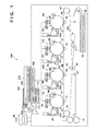
- FIG. 1 is a configuration diagram of an image forming apparatus according to one embodiment.
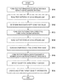
- FIG. 2 is a flowchart of processing for obtaining target density information according to one embodiment.
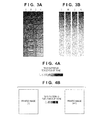
- FIGS. 3A and 3B are diagrams showing test patterns formed on a recording material according to one embodiment.
- FIGS. 4A and 4B are diagrams showing test patterns formed on a photosensitive member according to one embodiment.
- FIG. 5 is an illustrative diagram used to create a tone correction table in density correction control according to one embodiment.
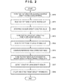
- FIG. 6 is a flowchart of density correction control according to one embodiment.
- FIG. 7 is a diagram showing correction information according to one embodiment.
- FIG. 8 is an illustrative diagram illustrating effects according to one embodiment.
- FIG. 9 is an illustrative diagram illustrating effects according to one embodiment.
- FIG. 1 is a configuration diagram of an image forming apparatus 100 according to the present embodiment.
- yellow, magenta, cyan and black image forming units PY, PM, PC and PK are arranged along an intermediate transfer belt 6 .
- the image forming unit PY includes a photosensitive member 1 Y, which is an image carrier and is rotationally driven in a direction indicated by an arrow in the diagram and charged to a predetermined potential by a charging unit 2 Y at the time of image forming.
- An exposure unit 3 Y scans the photosensitive member 1 Y with light, and exposes the photosensitive member 1 Y to light so as to form an electrostatic latent image on the surface of the photosensitive member 1 Y.
- a developing unit 4 Y outputs a developing bias, and supplies a yellow toner (coloring material) to the electrostatic latent image formed on the photosensitive member 1 Y so as to visualize the electrostatic latent image as a toner image.
- a primary transfer roller 7 Y outputs a primary transfer bias so as to transfer the toner image formed on the photosensitive member 1 Y onto the intermediate transfer belt 6 .
- the image forming unit PY also includes a density sensor 12 Y for detecting the density of the toner image formed on the photosensitive member 1 Y.
- the density sensor 12 Y emits light to, for example, the photosensitive member 1 Y, and detects the density by using specularly reflected light.
- the configuration of the density sensor 12 Y is not limited to detecting or measuring the density of the toner image formed on the photosensitive member, and the density sensor 12 Y may be configured to measure the density of the toner image transferred onto the intermediate transfer belt 6 , which will be described later.
- the image forming units PM, PC and PK and the image forming unit PY have the same configuration except that a different toner color is used. Accordingly, a description of the image forming units PM, PC and PK is omitted here. In the following description, the image forming units will be indicated by the reference alphabet without a suffix of Y, M, C or K unless it is necessary to distinguish the colors.
- the intermediate transfer belt 6 is an image carrier held under tension by three rollers 61 , 62 and 63 , and is rotationally driven in a direction indicated by R 2 in the diagram.
- a full color toner image is formed on the intermediate transfer belt 6 .
- a recording material P fed from a cassette 65 is conveyed toward a secondary transfer area T 2 including a roller 63 and a secondary transfer roller 64 by roller pairs 66 and 67 .
- the toner image that has been transferred onto the intermediate transfer belt 6 is then transferred onto the recording material P in the secondary transfer area T 2 .
- the recording material P is then heated and pressed by a fixing unit 11 so as to fix the toner image, and discharged to the outside of the apparatus.
- a light source 103 provided in a reading unit 216 irradiates an original placed on an original platen 102 with light.
- a CCD sensor 105 provided in the reading unit 216 reads the original by receiving reflected light from the original.
- Image data corresponding to the original read by the reading unit 216 is subjected to image processing in a reader image processing unit 108 , and transmitted to a printer control unit 109 .
- the printer control unit 109 executes, on the transmitted image data, image processing corresponding to each image forming unit PY, PM, PC or PK.
- the image forming apparatus 100 is configured not only to obtain image data corresponding to an original read by the reading unit 216 , but also to receive image data from a telephone line (FAX) or an external computer via a network.
- An operation unit 20 is used by the user so as to operate the image forming apparatus 100 , and includes a display unit 218 , such as a display, for displaying the state of the image forming apparatus 100 .
- a control unit 110 performs overall control on image forming operations of the image forming apparatus 100 , and includes a CPU 111 and storage units such as a RAM 112 and a ROM 113 .
- the control unit 110 obtains the density of the toner image formed on the photosensitive member 1 based on a signal from the density sensor 12 , which is a detection unit.
- the CPU 111 controls the image forming apparatus 100 by using programs and various types of data stored in the ROM 113 , and the RAM 112 as a work area. By the CPU 111 executing the programs, target density information obtaining processing, density correction control using the reading unit 216 , and density correction control using the density sensor 12 , which will be described below, are executed.
- the image forming apparatus 100 includes an environmental sensor 30 that obtains internal environmental information of the image forming apparatus, for example, either or both of temperature and humidity, and informs the control unit 110 of the internal environmental information.
- the control unit 110 carries out the density correction control using the reading unit 216 .
- the processing shown in FIG. 2 is performed by a user operation or when a predetermined condition is satisfied, and is performed with respect to each color.
- the control unit 110 forms a plurality of test patterns on a recording material based on predetermined image data.
- FIG. 3A shows examples of test patterns formed in S 10 .
- the image forming units PY, PM, PC and PK each form ten test patterns for their color.
- the amount of exposure light or exposure intensity is used as the image forming condition that is changed so as to control density, but a configuration is also possible in which another image forming condition regarding density is changed.
- a configuration may be used in which a value that determines a development contrast such as the developing bias supplied to the developing unit 4 or the charging bias supplied to the charging unit 2 is changed.
- a plurality of image forming conditions regarding density may be changed.
- the recording material having the test patterns of FIG. 3A formed thereon will be referred to as “test chart A”.
- the control unit 110 causes the reading unit 216 to read the test chart A, so as to measure the density of each test pattern.
- the control unit 110 determines, based on the density of each test pattern, an image forming condition with which the density of the toner image formed by using the predetermined image data as an input value achieves a target density.
- the target density is set to, for example, a maximum density that can be achieved by the image forming apparatus 100 .
- the amount of exposure light is used as the image forming condition for achieving the target density.
- the determined image forming condition is stored in the RAM 112 , and used in subsequent image forming operations.
- FIG. 3B shows examples of test patterns formed in S 13 .
- the test patterns shown in FIG. 3B are test patterns formed by using, for example, a plurality of values selected from a range of 0 to 255, namely, 64 values if the image data is 8-bit data.
- the recording material having the test patterns of FIG. 3B formed thereon will be referred to as “test chart B”. If the user places the test chart B on the reading unit 216 and issues an instruction to read the test chart B, in S 14 , the control unit 110 causes the reading unit 216 to read the test chart B, so as to measure the density of each test pattern.
- the control unit 110 In S 15 , the control unit 110 generates a tone correction table (reference tone correction table) based on the density of each test pattern, and stores the tone correction table in the RAM 112 .
- the tone correction table refers to information indicating a relationship between the input image data value (input value) and the value actually used in image forming (output value), and is a correction condition for correcting density characteristics of the image formed by the image forming apparatus 100 .
- the control unit 110 corrects image data based on the tone correction table, and causes the image forming unit PY, PM, PC or PK to form an image based on the corrected image data, whereby an image having a desired density can be formed.
- the control unit 110 If the target density characteristics is, for example, linear, the control unit 110 generates a tone correction table by reversing the relationship between the input value (255 value) of image data when the test chart B was formed and the density (255 value) of the test pattern of the test chart B.
- the method for generating a tone correction table any method can be used as long as the density characteristics of the image forming apparatus 100 can be corrected to desired density characteristics.
- the control unit 110 forms a test pattern R having ten levels of tone as shown in FIG. 4A on the photosensitive member 1 based on the reference tone correction table generated in S 15 , and in S 17 , the density sensor 12 detects a density in the test pattern R.
- the control unit 110 sets each density detected in the test pattern R in S 17 as a target density of the test pattern R, creates target density information indicating a relationship between the input value of image data and the target density of the test pattern R, and stores the target density information in the RAM 112 in S 18 .
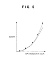
- the solid line shown in FIG. 5 indicates the target density information stored in S 18 .
- the target density is determined by interpolation calculation because there are only ten input values of image data.
- the density correction control using the density sensor 12 is carried out while the image forming apparatus 100 is forming a plurality of images, with reference to the flowchart of FIG. 6 .
- the density correction control using the reading unit 216 has poor usability because it requires the user to place the test chart A and the test chart B on the original platen 102 .
- the control unit 110 executes the density correction control using the density sensor 12 in order to stabilize the output density during a period between previous execution of the density correction control using the reading unit 216 and subsequent execution of the density correction control using the reading unit 216 .
- the density correction control using the density sensor 12 includes a tone correction (steps S 13 to S 15 of FIG.
- the density correction control using the density sensor 12 does not cause the reading unit 216 to read the test chart A and the test chart B.
- the tone correction using the density sensor 12 means to update the tone correction table (LUT) in S 25 .
- the maximum density correction using the density sensor 12 means to set the amount of exposure light again.
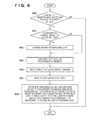
- the control unit 110 executes determination processing shown in FIG. 6 each time one page's worth of image information is formed. Hereinafter, the determination processing will be described.
- the control unit 110 determines whether the number of image-formed sheets has reached a threshold value N. In other words, the control unit 110 determines whether or not the image forming unit PY, PM, PC or PK has formed N page's worth of image information. If it is determined in S 20 that the number of image-formed sheets has not reached the threshold value N, the control unit 110 ends the determination processing.
- the control unit 110 determines whether or not it is necessary to change the amount of exposure light, and if it is determined that it is necessary to change the amount of exposure light, in S 22 , the control unit 110 changes the amount of exposure light. The method for determining whether or not it is necessary to change the amount of exposure light and the amount of adjustment if it is necessary to change the amount of exposure light will be described later. After that, the control unit 110 starts density correction control. First, in S 23 , the control unit 110 forms a test pattern Q having five levels of tone as shown in FIG. 4B on the photosensitive member 1 .
- the test pattern Q includes a maximum density measurement image formed by using a maximum input value and density measurement images having a density other than the maximum density. That is, the test pattern Q having five levels of tone includes a maximum density measurement image.
- the maximum density measurement image in the test pattern Q is formed by using the same input value as the input value of image data used to form the maximum density test pattern in the test pattern R. That is, if the input value of image data is, for example, a level of 255, the test pattern Q includes images formed by a signal level of 255.
- the control unit 110 detects the density of each measurement image in the test pattern Q by using the density sensor 12 . Then, in S 25 , the control unit 110 updates the tone correction table (LUT) based on the target density corresponding to a measurement image in the test pattern Q and the result of measurement (density) of the measurement image formed on the photosensitive member 1 based on the input value of image data corresponding to the test pattern Q.
- the target density corresponding to the measurement image in the test pattern Q is the measurement result of the measurement image in the test pattern R, which was stored in the RAM 112 in the target density information obtaining processing shown in FIG. 2 .
- tone correction table (LUT) is corrected such that a difference between the current density characteristics (broken line) and the target density information (solid line) is small.
- the corrected tone correction table (LUT) is stored in the RAM 112 .
- the updated tone correction table (LUT) is used in subsequent image forming operations. In this way, the tone correction using the density sensor 12 is performed.
- the control unit 110 determines whether or not it is necessary to change the amount of exposure light in the subsequent correction control according to a difference between the measurement result (density) of the maximum density measurement image in the test pattern Q and the target density of the same. Furthermore, in S 26 , the control unit 110 determines the threshold value N, which is an execution condition for executing subsequent tone correction and maximum density correction, according to that difference.
- the threshold value N specifies the frequency of execution of the correction control, and the execution timing of subsequent correct control is adjusted by using the threshold value N.
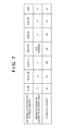
- the difference X between the measurement result (detection result) and the target density takes a negative value, it indicates that the measured density (detection result) is lower than the target density. If the difference X takes a positive value, it indicates that the measured density is higher than the target density. As shown in FIG. 7 , if the difference X is, for example, greater than ⁇ 20 and less than +20, it is unnecessary to change the amount of exposure light.
- the difference X is 20 or greater, it is necessary to change the amount of exposure light. For example, if the difference X is 20 or more and less than +30, it means that the density of the measurement image is higher than the target density, and thus the amount of exposure light is reduced by one unit so as to lower the density of the image.
- the amount of exposure light is changed by electric power or the like supplied to the exposure unit 3 .
- the control unit 110 controls the amount of exposure light by determining the amount of change (the amount of adjustment) based on the correction information shown in FIG. 7 , and setting a parameter such as the electric power supplied to the exposure unit 3 . Next, the method for setting the threshold value N will be described.
- the control unit 110 sets the threshold value N to, for example, 200. If, on the other hand, the absolute value of the difference X is greater than 20, it means that the density characteristics exhibits significant changes. If the absolute value of the difference X is greater than 20, the control unit 110 sets the threshold value N to a value smaller than 200 in order to increase the frequency of execution of the correction control. That is, if the difference X between the measured density and the target density exceeds a predetermined density, the control unit 110 reduces the threshold value N so as to increase the frequency of execution of the correction control.
- the control unit 110 determines whether or not it is necessary to adjust the amount of exposure light, and if it is determined that it is necessary to adjust the amount of exposure light, the control unit 110 determines the amount of adjustment of the amount of exposure light.
- the control unit 110 stores, in the RAM 112 , the result of determination made in S 26 and the amount of adjustment determined in S 26 .
- the control unit 110 also stores the threshold value N determined in S 26 in the RAM 112 . Then, at the time of subsequent execution of the determination processing (S 20 ), the control unit 110 reads the threshold value N from the RAM 112 , and compares the threshold value N with the number of image-formed sheets.
- the control unit 110 determines whether or not it is necessary to change the amount of exposure light based on the information stored in the RAM 112 , and sets the amount of adjustment used when the amount of exposure light is changed by reading it from the RAM 112 .
- the present embodiment is configured to, instead of immediately changing the amount of exposure light in S 26 , reflect the change at the time of subsequent execution of the density correction control using the density sensor 12 .
- FIG. 8 is a diagram showing changes in output density in the case where the frequency of execution of the density correction control using the density sensor 12 was fixed.
- the diagram shows changes in the density of a predetermined intermediate density image in the case where 5000 low density images are continuously formed and thereafter 1000 high density images are continuously formed.
- low density image refers to an image in which the toner application area is about 0.5% with respect to the total area of the recording material
- high density image refers to an image in which the toner application area is about 50% with respect to the total area of the recording material. Continuously forming low density images increases the time during which toner is stirred in the developing unit 4 , resulting in an increase in the amount of charge of toner.
- the density correction control using the density sensor 12 corrects the amount of exposure light and the tone correction table, and thus variations in the density of the image are suppressed, and images having the target density can be formed. After that, when forming of high density images starts, the time during which toner is stirred in the developing unit 4 is shortened, and the amount of charge of toner drops rapidly. If the amount of charge of toner drops, the amount of toner attached to the electrostatic latent image formed on the photosensitive member increases.
- the threshold value N used in the density correction control is fixed to 100 , the amount of exposure light and the tone correction table are not corrected at an appropriate timing, and thus it is not possible to keep up with the rapid changes in the density characteristics, and significant variations occur in the image density.
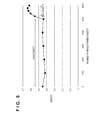
- FIG. 9 is a diagram showing changes in output density in the case where the threshold value N used in the density correction control was changed based on the correction information shown in FIG. 7 .
- the measurement conditions were the same as those of FIG. 8 .
- the threshold value N was changed to 25, and accordingly, the frequency of execution of the density correction control increased as compared to the conventional configuration ( FIG. 8 ). For this reason, the image density was maintained at a substantially constant level even when the density characteristics varied significantly.
- the threshold value N was changed to 200, and thus the frequency of execution of the density correction control decreased. Accordingly, productivity was improved as compared to the conventional configuration ( FIG. 8 ) because the frequency of execution of the density correction control using the density sensor 12 is suppressed if the variation in the density characteristics is small, while the image density is maintained at a substantially constant level.
- the test pattern R has ten levels of tone and the test pattern Q has five levels of tone, but the test patterns may have a different number of tone levels.
- the threshold value N is determined based on the measured density of the maximum density image of the test pattern Q and the target density of the same. However, the threshold value N may be determined by a difference between the measured density of a measurement image other than the maximum density measurement image in the test pattern Q and a target density corresponding to that measurement image.
- the number of image-formed sheets is used as a parameter used to determine whether or not to execute density correction control, but it is also possible to use other parameters such as an elapsed time since the previous update of the tone correction table.
- the density of the test pattern R is read by the reading unit 216 , but it is also possible to use a configuration in which, for example, the test patterns formed on a recording material is read by a sensor provided on the downstream side of the fixing unit 11 .
- control unit 110 is configured to, in S 25 of FIG. 6 , update the tone correction table (LUT) based on the measurement results (densities) of all measurement images in the test pattern Q and the target densities.
- control unit 110 may be configured to update the tone correction table (LUT) based on the measured densities of measurement images other than the maximum density measurement image in the test pattern Q and the target densities for the measurement images other than the maximum density measurement image in the test pattern Q.
- control unit 110 makes an assumption that the measured density of the maximum density measurement image is the target maximum density, and updates the tone correction table (LUT) based on the assumed target maximum density, the measured densities of measurement images other than the maximum density measurement image, and the target densities for the measurement images other than the maximum density measurement image.
- LUT tone correction table
- Embodiments of the present invention can also be realized by a computer of a system or apparatus that reads out and executes computer executable instructions (e.g., one or more programs) recorded on a storage medium (which may also be referred to more fully as a ‘non-transitory computer-readable storage medium’) to perform the functions of one or more of the above-described embodiments and/or that includes one or more circuits (e.g., application specific integrated circuit (ASIC)) for performing the functions of one or more of the above-described embodiments, and by a method performed by the computer of the system or apparatus by, for example, reading out and executing the computer executable instructions from the storage medium to perform the functions of one or more of the above-described embodiments and/or controlling the one or more circuits to perform the functions of one or more of the above-described embodiments.
- computer executable instructions e.g., one or more programs
- a storage medium which may also be referred to more fully as a ‘non-transitory computer-
- the computer may comprise one or more processors (e.g., central processing unit (CPU), micro processing unit (MPU)) and may include a network of separate computers or separate processors to read out and execute the computer executable instructions.
- the computer executable instructions may be provided to the computer, for example, from a network or the storage medium.
- the storage medium may include, for example, one or more of a hard disk, a random-access memory (RAM), a read only memory (ROM), a storage of distributed computing systems, an optical disk (such as a compact disc (CD), digital versatile disc (DVD), or Blu-ray Disc (BD)TM), a flash memory device, a memory card, and the like.
Landscapes
- Physics & Mathematics (AREA)
- General Physics & Mathematics (AREA)
- Engineering & Computer Science (AREA)
- Microelectronics & Electronic Packaging (AREA)
- Control Or Security For Electrophotography (AREA)
Abstract
Description
- 1. Field of the Invention
- The present invention relates to a density correction technique for use in an image forming apparatus.
- 2. Description of the Related Art
- Electrophotographic image forming apparatuses are required to provide density stability and tone stability of output images. For this reason, U.S. Pat. No. 5,752,126 and U.S. Pat. No. 5,583,644 disclose density correction control that stabilizes the quality of resulting images by forming a test pattern, which is a density correction image, detecting the density of the test pattern, and determining an image forming condition based on the detected density. The density correction control is executed, for example, each time image forming is performed on a predetermined number of sheets.
- A variation in the characteristics of an image forming apparatus that affects the density and tone of output images is not always proportional to, for example, the number of image-formed sheets, and accordingly, the following problems may occur when density correction control is performed based on a predetermined number of image-formed sheets. For example, density correction control may be performed at an unnecessary timing despite the fact that the density of output images is stable, or density correction control may not be performed at a necessary timing despite the fact that the density of output images is changing. If density correction control is performed at an unnecessary timing, the productivity of the image forming apparatus decreases. If density correction control is not performed at a necessary timing, the quality of output images decreases.
- According to an aspect of the present invention, an image forming apparatus includes: a converting unit configured to convert image data based on a conversion condition; a photosensitive member; an exposure unit configured to emit light based on a set light intensity and to expose the photosensitive member to the light based on the converted image data to form an electrostatic latent image; a developing unit configured to develop the electrostatic latent image to form an image on the photosensitive member; a transfer unit configured to transfer the image formed by the developing unit onto a sheet; a measuring unit configured to measure a plurality of measurement images formed on the photosensitive member by the exposure unit and the developing unit, the plurality of measurement images including a first measurement image and second measurement images; a generation unit configured to generate the conversion condition based on second measurement data corresponding to the second measurement images measured by the measuring unit; a first determination unit configured to determine an execution condition based on first measurement data corresponding to the first measurement image measured by the measuring unit; and a second determination unit configured to determine the light intensity based on the first measurement data. A subsequent timing when the plurality of measurement images are to be formed is determined based on the execution condition determined by the first determination unit, the exposure unit updates the set light intensity to the light intensity determined by the second determination unit when the plurality of measurement images are formed at the subsequent timing, and the conversion condition for converting the image data is updated to the conversion condition generated by the generation unit after generation of the conversion condition by the generation unit, and before the subsequent timing.
- Further features of the present invention will become apparent from the following description of exemplary embodiments with reference to the attached drawings.
-
FIG. 1 is a configuration diagram of an image forming apparatus according to one embodiment. -
FIG. 2 is a flowchart of processing for obtaining target density information according to one embodiment. -
FIGS. 3A and 3B are diagrams showing test patterns formed on a recording material according to one embodiment. -
FIGS. 4A and 4B are diagrams showing test patterns formed on a photosensitive member according to one embodiment. -
FIG. 5 is an illustrative diagram used to create a tone correction table in density correction control according to one embodiment. -
FIG. 6 is a flowchart of density correction control according to one embodiment. -
FIG. 7 is a diagram showing correction information according to one embodiment. -
FIG. 8 is an illustrative diagram illustrating effects according to one embodiment. -
FIG. 9 is an illustrative diagram illustrating effects according to one embodiment. - Hereinafter, an exemplary embodiment of the present invention will be described with reference to the drawings. It is to be noted that the embodiment given below is merely an example, and thus is not intended to limit the scope of the present invention to the content of the embodiment. Also, in the diagrams described below, constituent elements that are not necessary in the description of the embodiment are not illustrated.
-
FIG. 1 is a configuration diagram of animage forming apparatus 100 according to the present embodiment. In theimage forming apparatus 100 shown inFIG. 1 , yellow, magenta, cyan and black image forming units PY, PM, PC and PK are arranged along anintermediate transfer belt 6. The image forming unit PY includes aphotosensitive member 1Y, which is an image carrier and is rotationally driven in a direction indicated by an arrow in the diagram and charged to a predetermined potential by acharging unit 2Y at the time of image forming. Anexposure unit 3Y scans thephotosensitive member 1Y with light, and exposes thephotosensitive member 1Y to light so as to form an electrostatic latent image on the surface of thephotosensitive member 1Y. A developingunit 4Y outputs a developing bias, and supplies a yellow toner (coloring material) to the electrostatic latent image formed on thephotosensitive member 1Y so as to visualize the electrostatic latent image as a toner image. Aprimary transfer roller 7Y outputs a primary transfer bias so as to transfer the toner image formed on thephotosensitive member 1Y onto theintermediate transfer belt 6. The image forming unit PY also includes adensity sensor 12Y for detecting the density of the toner image formed on thephotosensitive member 1Y. Thedensity sensor 12Y emits light to, for example, thephotosensitive member 1Y, and detects the density by using specularly reflected light. The configuration of thedensity sensor 12Y is not limited to detecting or measuring the density of the toner image formed on the photosensitive member, and thedensity sensor 12Y may be configured to measure the density of the toner image transferred onto theintermediate transfer belt 6, which will be described later. - The image forming units PM, PC and PK and the image forming unit PY have the same configuration except that a different toner color is used. Accordingly, a description of the image forming units PM, PC and PK is omitted here. In the following description, the image forming units will be indicated by the reference alphabet without a suffix of Y, M, C or K unless it is necessary to distinguish the colors.
- The
intermediate transfer belt 6 is an image carrier held under tension by threerollers photosensitive members 1 of the image forming units being transferred onto theintermediate transfer belt 6 in a superimposed manner, a full color toner image is formed on theintermediate transfer belt 6. A recording material P fed from acassette 65 is conveyed toward a secondary transfer area T2 including aroller 63 and asecondary transfer roller 64 byroller pairs intermediate transfer belt 6 is then transferred onto the recording material P in the secondary transfer area T2. The recording material P is then heated and pressed by afixing unit 11 so as to fix the toner image, and discharged to the outside of the apparatus. - A
light source 103 provided in areading unit 216 irradiates an original placed on anoriginal platen 102 with light. ACCD sensor 105 provided in thereading unit 216 reads the original by receiving reflected light from the original. Image data corresponding to the original read by thereading unit 216 is subjected to image processing in a readerimage processing unit 108, and transmitted to aprinter control unit 109. Theprinter control unit 109 executes, on the transmitted image data, image processing corresponding to each image forming unit PY, PM, PC or PK. Theimage forming apparatus 100 according to the present embodiment is configured not only to obtain image data corresponding to an original read by thereading unit 216, but also to receive image data from a telephone line (FAX) or an external computer via a network. Anoperation unit 20 is used by the user so as to operate theimage forming apparatus 100, and includes adisplay unit 218, such as a display, for displaying the state of theimage forming apparatus 100. Acontrol unit 110 performs overall control on image forming operations of theimage forming apparatus 100, and includes aCPU 111 and storage units such as aRAM 112 and aROM 113. Thecontrol unit 110 obtains the density of the toner image formed on thephotosensitive member 1 based on a signal from thedensity sensor 12, which is a detection unit. TheCPU 111 controls theimage forming apparatus 100 by using programs and various types of data stored in theROM 113, and theRAM 112 as a work area. By theCPU 111 executing the programs, target density information obtaining processing, density correction control using thereading unit 216, and density correction control using thedensity sensor 12, which will be described below, are executed. Furthermore, theimage forming apparatus 100 includes anenvironmental sensor 30 that obtains internal environmental information of the image forming apparatus, for example, either or both of temperature and humidity, and informs thecontrol unit 110 of the internal environmental information. - Next is a description of the density correction control using the
reading unit 216 and the target density information obtaining processing with reference toFIG. 2 . In the case of executing the target density information obtaining processing, thecontrol unit 110 carries out the density correction control using thereading unit 216. The processing shown inFIG. 2 is performed by a user operation or when a predetermined condition is satisfied, and is performed with respect to each color. In S10, thecontrol unit 110 forms a plurality of test patterns on a recording material based on predetermined image data.FIG. 3A shows examples of test patterns formed in S10. The image forming units PY, PM, PC and PK each form ten test patterns for their color. The test patterns shown inFIG. 3A are test patterns formed by using, for example, a signal level of 255 if the image data is 8-bit data, and changing an image forming condition regarding density. In the following description, the amount of exposure light or exposure intensity is used as the image forming condition that is changed so as to control density, but a configuration is also possible in which another image forming condition regarding density is changed. To be specific, for example, a configuration may be used in which a value that determines a development contrast such as the developing bias supplied to the developing unit 4 or the charging bias supplied to thecharging unit 2 is changed. Furthermore, a plurality of image forming conditions regarding density may be changed. The recording material having the test patterns ofFIG. 3A formed thereon will be referred to as “test chart A”. If the user places the test chart A on thereading unit 216 and issues an instruction to read the test chart A, in S11, thecontrol unit 110 causes thereading unit 216 to read the test chart A, so as to measure the density of each test pattern. In S12, thecontrol unit 110 determines, based on the density of each test pattern, an image forming condition with which the density of the toner image formed by using the predetermined image data as an input value achieves a target density. The target density is set to, for example, a maximum density that can be achieved by theimage forming apparatus 100. As described above, in the present embodiment, the amount of exposure light is used as the image forming condition for achieving the target density. The determined image forming condition is stored in theRAM 112, and used in subsequent image forming operations. - Next, in S13, the
control unit 110 forms test patterns for correcting tone on a recording material.FIG. 3B shows examples of test patterns formed in S13. The test patterns shown inFIG. 3B are test patterns formed by using, for example, a plurality of values selected from a range of 0 to 255, namely, 64 values if the image data is 8-bit data. The recording material having the test patterns ofFIG. 3B formed thereon will be referred to as “test chart B”. If the user places the test chart B on thereading unit 216 and issues an instruction to read the test chart B, in S14, thecontrol unit 110 causes thereading unit 216 to read the test chart B, so as to measure the density of each test pattern. In S15, thecontrol unit 110 generates a tone correction table (reference tone correction table) based on the density of each test pattern, and stores the tone correction table in theRAM 112. The tone correction table refers to information indicating a relationship between the input image data value (input value) and the value actually used in image forming (output value), and is a correction condition for correcting density characteristics of the image formed by theimage forming apparatus 100. Thecontrol unit 110 corrects image data based on the tone correction table, and causes the image forming unit PY, PM, PC or PK to form an image based on the corrected image data, whereby an image having a desired density can be formed. If the target density characteristics is, for example, linear, thecontrol unit 110 generates a tone correction table by reversing the relationship between the input value (255 value) of image data when the test chart B was formed and the density (255 value) of the test pattern of the test chart B. As the method for generating a tone correction table, any method can be used as long as the density characteristics of theimage forming apparatus 100 can be corrected to desired density characteristics. After that, in S16, thecontrol unit 110 forms a test pattern R having ten levels of tone as shown inFIG. 4A on thephotosensitive member 1 based on the reference tone correction table generated in S15, and in S17, thedensity sensor 12 detects a density in the test pattern R. Thecontrol unit 110 sets each density detected in the test pattern R in S17 as a target density of the test pattern R, creates target density information indicating a relationship between the input value of image data and the target density of the test pattern R, and stores the target density information in theRAM 112 in S18. The solid line shown inFIG. 5 indicates the target density information stored in S18. The target density is determined by interpolation calculation because there are only ten input values of image data. - A description is now given of the density correction control using the
density sensor 12, which is carried out while theimage forming apparatus 100 is forming a plurality of images, with reference to the flowchart ofFIG. 6 . The density correction control using thereading unit 216 has poor usability because it requires the user to place the test chart A and the test chart B on theoriginal platen 102. For this reason, thecontrol unit 110 executes the density correction control using thedensity sensor 12 in order to stabilize the output density during a period between previous execution of the density correction control using thereading unit 216 and subsequent execution of the density correction control using thereading unit 216. The density correction control using thedensity sensor 12 includes a tone correction (steps S13 to S15 ofFIG. 2 ) and a maximum density correction (steps S10 to S12 ofFIG. 2 ), as with the density correction control using thereading unit 216. However, unlike the density correction control using thereading unit 216, the density correction control using thedensity sensor 12 does not cause thereading unit 216 to read the test chart A and the test chart B. The tone correction using thedensity sensor 12 means to update the tone correction table (LUT) in S25. Likewise, the maximum density correction using thedensity sensor 12 means to set the amount of exposure light again. Thecontrol unit 110 executes determination processing shown inFIG. 6 each time one page's worth of image information is formed. Hereinafter, the determination processing will be described. In S20, after previous execution of the density correction control using thedensity sensor 12 or the target density information obtaining processing using thereading unit 216, thecontrol unit 110 determines whether the number of image-formed sheets has reached a threshold value N. In other words, thecontrol unit 110 determines whether or not the image forming unit PY, PM, PC or PK has formed N page's worth of image information. If it is determined in S20 that the number of image-formed sheets has not reached the threshold value N, thecontrol unit 110 ends the determination processing. If it is determined that the number of image-formed sheets has reached the threshold value N, in S21, thecontrol unit 110 determines whether or not it is necessary to change the amount of exposure light, and if it is determined that it is necessary to change the amount of exposure light, in S22, thecontrol unit 110 changes the amount of exposure light. The method for determining whether or not it is necessary to change the amount of exposure light and the amount of adjustment if it is necessary to change the amount of exposure light will be described later. After that, thecontrol unit 110 starts density correction control. First, in S23, thecontrol unit 110 forms a test pattern Q having five levels of tone as shown inFIG. 4B on thephotosensitive member 1. The test pattern Q includes a maximum density measurement image formed by using a maximum input value and density measurement images having a density other than the maximum density. That is, the test pattern Q having five levels of tone includes a maximum density measurement image. The maximum density measurement image in the test pattern Q is formed by using the same input value as the input value of image data used to form the maximum density test pattern in the test pattern R. That is, if the input value of image data is, for example, a level of 255, the test pattern Q includes images formed by a signal level of 255. - In S24, the
control unit 110 detects the density of each measurement image in the test pattern Q by using thedensity sensor 12. Then, in S25, thecontrol unit 110 updates the tone correction table (LUT) based on the target density corresponding to a measurement image in the test pattern Q and the result of measurement (density) of the measurement image formed on thephotosensitive member 1 based on the input value of image data corresponding to the test pattern Q. The target density corresponding to the measurement image in the test pattern Q is the measurement result of the measurement image in the test pattern R, which was stored in theRAM 112 in the target density information obtaining processing shown inFIG. 2 . To be specific, a relationship between image data values and measurement results (densities) of five measurement images is interpolated so as to obtain the current density characteristics indicated by the broken line inFIG. 5 . Then, the tone correction table (LUT) is corrected such that a difference between the current density characteristics (broken line) and the target density information (solid line) is small. The corrected tone correction table (LUT) is stored in theRAM 112. The updated tone correction table (LUT) is used in subsequent image forming operations. In this way, the tone correction using thedensity sensor 12 is performed. - After that, in S26, the
control unit 110 determines whether or not it is necessary to change the amount of exposure light in the subsequent correction control according to a difference between the measurement result (density) of the maximum density measurement image in the test pattern Q and the target density of the same. Furthermore, in S26, thecontrol unit 110 determines the threshold value N, which is an execution condition for executing subsequent tone correction and maximum density correction, according to that difference. The threshold value N specifies the frequency of execution of the correction control, and the execution timing of subsequent correct control is adjusted by using the threshold value N.FIG. 7 shows a relationship between the amount of change (the amount of adjustment) used when the amount of exposure light is changed and the threshold value N with respect to a difference X between the measurement result of the maximum density measurement image in the test pattern Q and the target density, which is stored in theROM 113 in advance, for example. If the difference X between the measurement result (detection result) and the target density takes a negative value, it indicates that the measured density (detection result) is lower than the target density. If the difference X takes a positive value, it indicates that the measured density is higher than the target density. As shown inFIG. 7 , if the difference X is, for example, greater than −20 and less than +20, it is unnecessary to change the amount of exposure light. If, on the other hand, the difference X is 20 or greater, it is necessary to change the amount of exposure light. For example, if the difference X is 20 or more and less than +30, it means that the density of the measurement image is higher than the target density, and thus the amount of exposure light is reduced by one unit so as to lower the density of the image. The amount of exposure light is changed by electric power or the like supplied to theexposure unit 3. Thecontrol unit 110 controls the amount of exposure light by determining the amount of change (the amount of adjustment) based on the correction information shown inFIG. 7 , and setting a parameter such as the electric power supplied to theexposure unit 3. Next, the method for setting the threshold value N will be described. If the difference X is greater than −20 and less than +20, the density characteristics exhibits less changes. In this case, thecontrol unit 110 sets the threshold value N to, for example, 200. If, on the other hand, the absolute value of the difference X is greater than 20, it means that the density characteristics exhibits significant changes. If the absolute value of the difference X is greater than 20, thecontrol unit 110 sets the threshold value N to a value smaller than 200 in order to increase the frequency of execution of the correction control. That is, if the difference X between the measured density and the target density exceeds a predetermined density, thecontrol unit 110 reduces the threshold value N so as to increase the frequency of execution of the correction control. - In the processing of S26, the
control unit 110 determines whether or not it is necessary to adjust the amount of exposure light, and if it is determined that it is necessary to adjust the amount of exposure light, thecontrol unit 110 determines the amount of adjustment of the amount of exposure light. Thecontrol unit 110 stores, in theRAM 112, the result of determination made in S26 and the amount of adjustment determined in S26. Thecontrol unit 110 also stores the threshold value N determined in S26 in theRAM 112. Then, at the time of subsequent execution of the determination processing (S20), thecontrol unit 110 reads the threshold value N from theRAM 112, and compares the threshold value N with the number of image-formed sheets. By doing so, the number of times of execution of correction control is suppressed if the density characteristics exhibits less changes, and the correction control is executed frequently if the density characteristics exhibits significant changes. Furthermore, in S21, thecontrol unit 110 determines whether or not it is necessary to change the amount of exposure light based on the information stored in theRAM 112, and sets the amount of adjustment used when the amount of exposure light is changed by reading it from theRAM 112. The present embodiment is configured to, instead of immediately changing the amount of exposure light in S26, reflect the change at the time of subsequent execution of the density correction control using thedensity sensor 12. This is done so because if the amount of exposure light is changed immediately, the amount of exposure light used in subsequent image forming is different from the amount of exposure light used at the time of forming the test pattern Q, based on which the LUT was updated. That is, if image forming is performed by using an amount of exposure light that is different from the amount of exposure light based on which the LUT used was determined, it is not possible to properly correct tone. -
FIG. 8 is a diagram showing changes in output density in the case where the frequency of execution of the density correction control using thedensity sensor 12 was fixed. The diagram shows changes in the density of a predetermined intermediate density image in the case where 5000 low density images are continuously formed and thereafter 1000 high density images are continuously formed. As used herein, “low density image” refers to an image in which the toner application area is about 0.5% with respect to the total area of the recording material, and “high density image” refers to an image in which the toner application area is about 50% with respect to the total area of the recording material. Continuously forming low density images increases the time during which toner is stirred in the developing unit 4, resulting in an increase in the amount of charge of toner. If the amount of charge of toner increases, the amount of toner applied to the electrostatic latent image formed on the photosensitive member decreases, and thus the formed image has a low density. However, the density correction control using thedensity sensor 12 corrects the amount of exposure light and the tone correction table, and thus variations in the density of the image are suppressed, and images having the target density can be formed. After that, when forming of high density images starts, the time during which toner is stirred in the developing unit 4 is shortened, and the amount of charge of toner drops rapidly. If the amount of charge of toner drops, the amount of toner attached to the electrostatic latent image formed on the photosensitive member increases. In the case where the threshold value N used in the density correction control is fixed to 100, the amount of exposure light and the tone correction table are not corrected at an appropriate timing, and thus it is not possible to keep up with the rapid changes in the density characteristics, and significant variations occur in the image density. - On the other hand,
FIG. 9 is a diagram showing changes in output density in the case where the threshold value N used in the density correction control was changed based on the correction information shown inFIG. 7 . The measurement conditions were the same as those ofFIG. 8 . In this case, after the start of forming of high density images, the threshold value N was changed to 25, and accordingly, the frequency of execution of the density correction control increased as compared to the conventional configuration (FIG. 8 ). For this reason, the image density was maintained at a substantially constant level even when the density characteristics varied significantly. Also, after 2000 low density images had been formed, the threshold value N was changed to 200, and thus the frequency of execution of the density correction control decreased. Accordingly, productivity was improved as compared to the conventional configuration (FIG. 8 ) because the frequency of execution of the density correction control using thedensity sensor 12 is suppressed if the variation in the density characteristics is small, while the image density is maintained at a substantially constant level. - Note that specific values used in the embodiment described above are merely examples. For example, the test pattern R has ten levels of tone and the test pattern Q has five levels of tone, but the test patterns may have a different number of tone levels. Also, in the embodiment described above, the threshold value N is determined based on the measured density of the maximum density image of the test pattern Q and the target density of the same. However, the threshold value N may be determined by a difference between the measured density of a measurement image other than the maximum density measurement image in the test pattern Q and a target density corresponding to that measurement image. In the present embodiment, the number of image-formed sheets is used as a parameter used to determine whether or not to execute density correction control, but it is also possible to use other parameters such as an elapsed time since the previous update of the tone correction table. Furthermore, in the processing shown in
FIG. 2 , the density of the test pattern R is read by thereading unit 216, but it is also possible to use a configuration in which, for example, the test patterns formed on a recording material is read by a sensor provided on the downstream side of the fixingunit 11. - In addition, in the embodiment described above, the
control unit 110 is configured to, in S25 ofFIG. 6 , update the tone correction table (LUT) based on the measurement results (densities) of all measurement images in the test pattern Q and the target densities. However, thecontrol unit 110 may be configured to update the tone correction table (LUT) based on the measured densities of measurement images other than the maximum density measurement image in the test pattern Q and the target densities for the measurement images other than the maximum density measurement image in the test pattern Q. In this case, thecontrol unit 110 makes an assumption that the measured density of the maximum density measurement image is the target maximum density, and updates the tone correction table (LUT) based on the assumed target maximum density, the measured densities of measurement images other than the maximum density measurement image, and the target densities for the measurement images other than the maximum density measurement image. - Embodiments of the present invention can also be realized by a computer of a system or apparatus that reads out and executes computer executable instructions (e.g., one or more programs) recorded on a storage medium (which may also be referred to more fully as a ‘non-transitory computer-readable storage medium’) to perform the functions of one or more of the above-described embodiments and/or that includes one or more circuits (e.g., application specific integrated circuit (ASIC)) for performing the functions of one or more of the above-described embodiments, and by a method performed by the computer of the system or apparatus by, for example, reading out and executing the computer executable instructions from the storage medium to perform the functions of one or more of the above-described embodiments and/or controlling the one or more circuits to perform the functions of one or more of the above-described embodiments. The computer may comprise one or more processors (e.g., central processing unit (CPU), micro processing unit (MPU)) and may include a network of separate computers or separate processors to read out and execute the computer executable instructions. The computer executable instructions may be provided to the computer, for example, from a network or the storage medium. The storage medium may include, for example, one or more of a hard disk, a random-access memory (RAM), a read only memory (ROM), a storage of distributed computing systems, an optical disk (such as a compact disc (CD), digital versatile disc (DVD), or Blu-ray Disc (BD)™), a flash memory device, a memory card, and the like.
- While the present invention has been described with reference to exemplary embodiments, it is to be understood that the invention is not limited to the disclosed exemplary embodiments. The scope of the following claims is to be accorded the broadest interpretation so as to encompass all such modifications and equivalent structures and functions.
- This application claims the benefit of Japanese Patent Application No. 2014-189444, filed on Sep. 17, 2014, which is hereby incorporated by reference herein in its entirety.
Claims (20)
Applications Claiming Priority (2)
| Application Number | Priority Date | Filing Date | Title |
|---|---|---|---|
| JP2014-189444 | 2014-09-17 | ||
| JP2014189444A JP6486044B2 (en) | 2014-09-17 | 2014-09-17 | Image forming apparatus |
Publications (2)
| Publication Number | Publication Date |
|---|---|
| US20160077458A1 true US20160077458A1 (en) | 2016-03-17 |
| US9459579B2 US9459579B2 (en) | 2016-10-04 |
Family
ID=55454662
Family Applications (1)
| Application Number | Title | Priority Date | Filing Date |
|---|---|---|---|
| US14/850,259 Active US9459579B2 (en) | 2014-09-17 | 2015-09-10 | Image forming apparatus that corrects image forming condition based on measurement result of measurement image |
Country Status (2)
| Country | Link |
|---|---|
| US (1) | US9459579B2 (en) |
| JP (1) | JP6486044B2 (en) |
Cited By (5)
| Publication number | Priority date | Publication date | Assignee | Title |
|---|---|---|---|---|
| US9977365B2 (en) * | 2016-04-20 | 2018-05-22 | Canon Kabushiki Kaisha | Image forming apparatus with correction of exposure light using measurement image |
| US20180284675A1 (en) * | 2017-03-29 | 2018-10-04 | Canon Kabushiki Kaisha | Image forming apparatus that controls image density |
| US10324407B2 (en) | 2016-07-12 | 2019-06-18 | Canon Kabushiki Kaisha | Image forming apparatus |
| US20230064610A1 (en) * | 2021-08-25 | 2023-03-02 | Canon Kabushiki Kaisha | Information processing apparatus |
| US20240330633A1 (en) * | 2023-03-27 | 2024-10-03 | Kyocera Document Solutions Inc. | Image forming apparatus and image quality adjustment method capable of suppressing user's perception of change in image quality caused by adjustment of image quality of output image |
Families Citing this family (1)
| Publication number | Priority date | Publication date | Assignee | Title |
|---|---|---|---|---|
| JP6921489B2 (en) | 2016-07-13 | 2021-08-18 | キヤノン株式会社 | Image forming device |
Family Cites Families (12)
| Publication number | Priority date | Publication date | Assignee | Title |
|---|---|---|---|---|
| EP0628887A3 (en) | 1991-02-22 | 1995-07-19 | Canon Kk | Image forming apparatus. |
| JP3274200B2 (en) | 1992-12-28 | 2002-04-15 | キヤノン株式会社 | Image forming method and apparatus |
| JPH08251367A (en) * | 1995-03-07 | 1996-09-27 | Minolta Co Ltd | Digital image forming device |
| JP3552486B2 (en) * | 1997-09-22 | 2004-08-11 | ミノルタ株式会社 | Image forming device |
| JP3633429B2 (en) * | 2000-03-24 | 2005-03-30 | 松下電器産業株式会社 | Color image forming apparatus |
| US6519425B2 (en) * | 2001-02-23 | 2003-02-11 | Hewlett-Packard Company | Image-producing methods and apparatus |
| JP2003035979A (en) * | 2001-07-23 | 2003-02-07 | Canon Inc | Image forming apparatus and developing apparatus |
| JP2005195973A (en) * | 2004-01-08 | 2005-07-21 | Konica Minolta Business Technologies Inc | Image forming apparatus and image forming method |
| JP5006625B2 (en) * | 2006-12-01 | 2012-08-22 | キヤノン株式会社 | Image forming apparatus |
| JP5006676B2 (en) * | 2007-03-27 | 2012-08-22 | シャープ株式会社 | Image density correction method and image forming apparatus |
| JP5418265B2 (en) * | 2010-02-08 | 2014-02-19 | 株式会社リコー | Image forming apparatus |
| JP5418914B2 (en) * | 2010-03-18 | 2014-02-19 | 株式会社リコー | Image forming apparatus |
-
2014
- 2014-09-17 JP JP2014189444A patent/JP6486044B2/en active Active
-
2015
- 2015-09-10 US US14/850,259 patent/US9459579B2/en active Active
Cited By (7)
| Publication number | Priority date | Publication date | Assignee | Title |
|---|---|---|---|---|
| US9977365B2 (en) * | 2016-04-20 | 2018-05-22 | Canon Kabushiki Kaisha | Image forming apparatus with correction of exposure light using measurement image |
| US10324407B2 (en) | 2016-07-12 | 2019-06-18 | Canon Kabushiki Kaisha | Image forming apparatus |
| US20180284675A1 (en) * | 2017-03-29 | 2018-10-04 | Canon Kabushiki Kaisha | Image forming apparatus that controls image density |
| US10394175B2 (en) * | 2017-03-29 | 2019-08-27 | Canon Kabushiki Kaisha | Image forming apparatus that uses a predetermined measurement image and controls image density |
| US20230064610A1 (en) * | 2021-08-25 | 2023-03-02 | Canon Kabushiki Kaisha | Information processing apparatus |
| US12061825B2 (en) * | 2021-08-25 | 2024-08-13 | Canon Kabushiki Kaisha | Information processing apparatus |
| US20240330633A1 (en) * | 2023-03-27 | 2024-10-03 | Kyocera Document Solutions Inc. | Image forming apparatus and image quality adjustment method capable of suppressing user's perception of change in image quality caused by adjustment of image quality of output image |
Also Published As
| Publication number | Publication date |
|---|---|
| US9459579B2 (en) | 2016-10-04 |
| JP2016061924A (en) | 2016-04-25 |
| JP6486044B2 (en) | 2019-03-20 |
Similar Documents
| Publication | Publication Date | Title |
|---|---|---|
| US10057459B2 (en) | Image forming apparatus, updating method of gamma correction information, and storage medium | |
| US9459579B2 (en) | Image forming apparatus that corrects image forming condition based on measurement result of measurement image | |
| US8988728B2 (en) | Calibration method executed in image forming apparatus | |
| US9310742B2 (en) | Image forming apparatus that updates process condition of image formation | |
| US9372460B2 (en) | Image forming apparatus holding tone correction table | |
| US9436145B2 (en) | Image forming apparatus including correction unit that corrects tone correction table | |
| US9261840B2 (en) | Method of determining process condition of image forming apparatus | |
| JP2015073162A (en) | Image forming apparatus, and update method of correction value of shading correction | |
| US9819826B2 (en) | Image forming apparatus that controls image forming conditions for adjusting image density | |
| US9678463B2 (en) | Image forming apparatus that adjusts maximum density | |
| US9933740B2 (en) | Image forming apparatus that generates conversion condition based on measurement result and first coefficient, and where chromatic color image is formed after predetermined number of monochrome images, generates conversion condition based on new measurement result and second coefficient | |
| US9851672B2 (en) | Image forming apparatus that adjusts image forming conditions | |
| US20250119506A1 (en) | Image-forming apparatus for suppressing image unevenness | |
| US10331068B2 (en) | Image forming apparatus performing density adjustment control | |
| JP6666932B2 (en) | Image forming device | |
| JP6562786B2 (en) | Image forming apparatus | |
| JP6244969B2 (en) | Image forming apparatus and gradation pattern forming method | |
| JP6745062B2 (en) | Image forming device | |
| US12072643B2 (en) | Image forming apparatus for correcting density unevenness in a scanning direction | |
| US20240320456A1 (en) | Image forming apparatus for creating image forming condition | |
| US20190037101A1 (en) | Image forming apparatus that converts image data based on conversion condition corresponding to type of halftone process | |
| JP2015197470A (en) | image forming apparatus | |
| JP6624096B2 (en) | Image forming apparatus, voltage adjustment method | |
| JP2017129689A (en) | Image formation apparatus, gradation correction apparatus, gradation correction program, and gradation correction method | |
| JP6604767B2 (en) | Image forming apparatus |
Legal Events
| Date | Code | Title | Description |
|---|---|---|---|
| AS | Assignment |
Owner name: CANON KABUSHIKI KAISHA, JAPAN Free format text: ASSIGNMENT OF ASSIGNORS INTEREST;ASSIGNOR:SHIRAFUJI, YASUHITO;REEL/FRAME:037577/0888 Effective date: 20150827 |
|
| STCF | Information on status: patent grant |
Free format text: PATENTED CASE |
|
| MAFP | Maintenance fee payment |
Free format text: PAYMENT OF MAINTENANCE FEE, 4TH YEAR, LARGE ENTITY (ORIGINAL EVENT CODE: M1551); ENTITY STATUS OF PATENT OWNER: LARGE ENTITY Year of fee payment: 4 |
|
| MAFP | Maintenance fee payment |
Free format text: PAYMENT OF MAINTENANCE FEE, 8TH YEAR, LARGE ENTITY (ORIGINAL EVENT CODE: M1552); ENTITY STATUS OF PATENT OWNER: LARGE ENTITY Year of fee payment: 8 |