US2015405A - Igniter for gas burners - Google Patents
Igniter for gas burners Download PDFInfo
- Publication number
- US2015405A US2015405A US471180A US47118030A US2015405A US 2015405 A US2015405 A US 2015405A US 471180 A US471180 A US 471180A US 47118030 A US47118030 A US 47118030A US 2015405 A US2015405 A US 2015405A
- Authority
- US
- United States
- Prior art keywords
- burner
- gas
- tube
- torch head
- flame
- Prior art date
- Legal status (The legal status is an assumption and is not a legal conclusion. Google has not performed a legal analysis and makes no representation as to the accuracy of the status listed.)
- Expired - Lifetime
Links
Images
Classifications
-
- F—MECHANICAL ENGINEERING; LIGHTING; HEATING; WEAPONS; BLASTING
- F24—HEATING; RANGES; VENTILATING
- F24C—DOMESTIC STOVES OR RANGES ; DETAILS OF DOMESTIC STOVES OR RANGES, OF GENERAL APPLICATION
- F24C3/00—Stoves or ranges for gaseous fuels
- F24C3/10—Arrangement or mounting of ignition devices
- F24C3/106—Arrangement or mounting of ignition devices of flash tubes
Definitions
- the instant invention provides means for automatically reigniting the, gas issuing from the burner in cases where the flame is extinguished 20 as above pointed out.
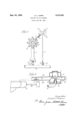
- Figure 1 is a plan view of an arrangement embodying my invention.
- Figure 2 is a partial sectional view taken on the line 22 of Figure 1, looking in the direction indicated by the arrows.
- the usual gas manifold is illustrated at 3.
- the gas burner is illustrated at 4, this burner being fed from the manifold 3 by the usual feed pipe 5, to which air is admitted, in the usual way, at the end nearest the manifold.
- Gaseous fuel is lead into the feed pipe 5 by way of the nozzle pipe 6, from manifold 3, in which nozzle pipe the usual gas cook I is provided.
- An igniter is provided in appropriate proximity to the burner 4.
- This igniter comprises a tube 8 leading from the manifold 3 and terminating in a torch head 9 an appropriate distance from the 40 burner 4.
- gas ranges embody a number of burners, usually four, and the torch ,head 9 is disposed centrally within these circularly arranged burners.
- a protecting hood I is 45 mounted over the torch head 9 upon a flanged perforated collar I2 supported on the upcurved end of the tube 8, as shown in Figure 2, below the torch head.
- the hood II] has the flue II, opening at. the top, and four openings I3, I3 in the V V 50 circular side wall, each in line with the respective burner on the range.
- a tube I I leads from each opening I3 toward the respective burner, as illustrated, each of these tubes having the longitudinally slot I4 at the bottom thereof to 55 provide for the entry of air.
- each of the tubes I I, M extends a short distance into the hood I0 and its inner end at the top is provided with an ear I l in clamping engagement with the flue member I I, the upper end of which,
- the torch head 9 has a pilot flame opening I6 and is fed by Way of the tube 8 from the manifold 3, a coupling I5 being provided.
- This type of coupling is shown in Patent 1,747,015 and detailed 10 description here is unnecessary. Sufiice it to say, for present purposes, that this coupling has a constant by-pass, adjustable by the valve screw I5, by which arrangement a constant pilot light is maintained at the opening I6.
- This torch head has the port I8 drilled in the side thereof and so positioned as to be directed toward the burner l, and the port I9 drilled in the opposite side thereof and so positioned as to be directed toward the pilot flame at I6.
- the cock 1 associated with that burner is open and gas enters the burner ready to be ignited at the burner openings 4', 4'.
- Gas also passes through the tube IE to the torch head i! issuing therefrom in both directions, one stream of gas from the port I8 301 toward and over the burner 3 and the other stream of gasthrough the port 99 toward and to the pilot flame at I 6.
- the gas issuing from the port I9 in the torch head I? into the tube flows toward the torch head 9 and is ignited by the pilot flame.
- the flame is then conveyed back to the torch head I! and to the stream of gasv issuing from the port i8, thus causing a flame to be projected over the burner 4 to ignite the gas issuing from burner openings l.
- the gas issuing from the torch head I 7 remains ignited so long as the gas cock I is open and the continuing flame at I8 is essential to the instant invention as will now be pointed out.
- a gas burner means for maintaining a constant pilot flame
- a torch head spaced laterally of said burner, a conduit supporting said head and fed from said burner, said head having two ports, one directed toward said burner and one directed toward said pilot flame, and means for directing gas from the port directed toward the pilot flame to said pilot flame and the flame back from said pilot flame to said torch head, said means shielding said torch head.
- a gas burner means for maintaining a constant pilot flame, a tube between said burner and said pilot flame, and a torch head extending vertically into said tube at a point spaced laterally of said burner intermediate the ends of said tube, a conduit secured to said burner supporting said head and fed from said burner, said torch head having two ports, one directed toward said burner and one directed toward said pilot flame.
- a gas burner meansfor maintaining a constant pilot flame, a tube between said burner and said pilot flame, said tube having a slot in the bottom thereof for the entry of air, and a torch head extending into said tube and supported laterally of said burner by a conduit extending outwardly of and fed from said burner,
- said torch head having two ports, one directed toward said pilot flame and one directed toward said burner.
- a gas burner for maintaining a pilot flame, a hood over said torch head, a tube carried by said hood and terminating short of said burner, and a second torch head extending vertically into said tube intermediate its ends and fed from said burner, said second torch head having a port directed toward said burner and having additional means for feeding gas to said tube.
- a gas burner means for maintaining a pilot flame in proximity to said burner, a torch head, and means for supplying gas from the interior of said burner to said torch head including a conduit extending from the side wall of said burner and spacing said torch head from said burner, said torch head having two opposed lateral ports to direct streams of gas simultaneously one over said burner and the other to said pilot flame.
- a gas burner in appropriate proximity thereto, a port in said pilot light for maintaining a pilot flame, a hood for said pilot light having a lateral opening directed toward said burner, a tube secured to said hood and leading from said opening toward said burner, said tube terminating short of said burner, a torch head associated with said burner and positioned in said tube intermediate its ends, said head having a pair of oppositely disposed ports, one port being directed toward said burner, the other port being directed toward said pilot light.
- a gas burner in appropriate proximity thereto, a port in said pilot light for maintaining a pilot flame, a hood for said pilot light having an opening therein directed toward said burner, a tube secured to said hood and leading from said opening toward said burner, flue means disposed within said hood for causing a flow of fresh air through said tube, a torch head positioned near the outer extremity of said tube, said torch head having a pair of oppositely disposed ports projecting into and protected by said tube, and a conduit communicating with the interior of said burner at one end and extending laterally outwardly of said burner toward said pilot light, said torch head being supported on the opposite end of said conduit and fed thereby from said burner.
- a gas burner in proximity thereto, a port in said pilot light, a gas supply conduit supporting said pilot light, a hood positioned over said light and secured to said conduit, said hood having an opening therein di- 45 disposed ports directed oppositely in said tube for 55 transmitting a flame from said pilot light to said burner.
Description
Sept. M, W35, 0. J. LEINS IGNITER FOR GAS BURNERS Filed July 28, 1930,
Patented Sept. 24, 1935 UNITED STATES PATENT OFFICE 8 Claims. (01. 158115) The instant invention is in the nature of'an improvement on the lighting device illustrated 15" and described in United States Letters Patent No.
1,747,015, issued February 11, 1930.
The instant invention provides means for automatically reigniting the, gas issuing from the burner in cases where the flame is extinguished 20 as above pointed out.
My invention is illustrated in the accompanying drawing in which:-
Figure 1 is a plan view of an arrangement embodying my invention, and
25'. Figure 2 is a partial sectional view taken on the line 22 of Figure 1, looking in the direction indicated by the arrows.
The usual gas manifold is illustrated at 3. The gas burner is illustrated at 4, this burner being fed from the manifold 3 by the usual feed pipe 5, to which air is admitted, in the usual way, at the end nearest the manifold. Gaseous fuel is lead into the feed pipe 5 by way of the nozzle pipe 6, from manifold 3, in which nozzle pipe the usual gas cook I is provided.
An igniter is provided in appropriate proximity to the burner 4. This igniter comprises a tube 8 leading from the manifold 3 and terminating in a torch head 9 an appropriate distance from the 40 burner 4. Although only one burner is shown, it is, of course, understood that gas ranges embody a number of burners, usually four, and the torch ,head 9 is disposed centrally within these circularly arranged burners. A protecting hood I is 45 mounted over the torch head 9 upon a flanged perforated collar I2 supported on the upcurved end of the tube 8, as shown in Figure 2, below the torch head. The hood II] has the flue II, opening at. the top, and four openings I3, I3 in the V V 50 circular side wall, each in line with the respective burner on the range. A tube I I leads from each opening I3 toward the respective burner, as illustrated, each of these tubes having the longitudinally slot I4 at the bottom thereof to 55 provide for the entry of air. As illustrated, each of the tubes I I, M extends a short distance into the hood I0 and its inner end at the top is provided with an ear I l in clamping engagement with the flue member I I, the upper end of which,
in turn, is in clamping engagement with the top 5 of the hood.
The torch head 9 has a pilot flame opening I6 and is fed by Way of the tube 8 from the manifold 3, a coupling I5 being provided. This type of coupling is shown in Patent 1,747,015 and detailed 10 description here is unnecessary. Sufiice it to say, for present purposes, that this coupling has a constant by-pass, adjustable by the valve screw I5, by which arrangement a constant pilot light is maintained at the opening I6.
Extending from the burner 4 toward the re spective adjacent tube It is a small tube It which carries at its end the torch head ll extending upwardly into the respective tube I4, as illustrated. This torch head has the port I8 drilled in the side thereof and so positioned as to be directed toward the burner l, and the port I9 drilled in the opposite side thereof and so positioned as to be directed toward the pilot flame at I6.
When a burner d is to be ignited, the cock 1 associated with that burner is open and gas enters the burner ready to be ignited at the burner openings 4', 4'. Gas also passes through the tube IE to the torch head i! issuing therefrom in both directions, one stream of gas from the port I8 301 toward and over the burner 3 and the other stream of gasthrough the port 99 toward and to the pilot flame at I 6. The gas issuing from the port I9 in the torch head I? into the tube flows toward the torch head 9 and is ignited by the pilot flame. The flame is then conveyed back to the torch head I! and to the stream of gasv issuing from the port i8, thus causing a flame to be projected over the burner 4 to ignite the gas issuing from burner openings l. The gas issuing from the torch head I 7 remains ignited so long as the gas cock I is open and the continuing flame at I8 is essential to the instant invention as will now be pointed out.
It will be clear that the initial projection of the flame at I8 is due to the initial rush of gas into the burner 4, and before the pressure thereof is relieved by the issue of gas through the burner openings 4'. By the time the pressure is thus relieved, however, the gas issuing from the burner openings 4', or enough of them to light the others, is ignited and the flame at I8 then subsides to appropriate pilot proportions.
'In the event that liquid, boiling over the sides of a vessel disposed over the burner, falls upon the burner, and quenches the flame thereon, it does so just to the extent that the liquid fills the burner openings 4'. 'Just to the extent that burner openings 4 are closed the pressure within the burner is increased. This increase in pressure causes the projection of the flame from the port l8, over the burner, as indicated in Figure 2, and as soon as the filled burner openings become cleared by the evaporation of the liquid therein, the gas issuing therefrom is ignited by this temporarily projected flame. As such reignition takes, place, the gas pressure within the burner is obviously gradually restored and, accordingly, the
.flame at [8 gradually recedes to resume appropriate pilot proportions. Obviously, except for this automatic reignition, the gas which would issue from the cleared burner openings 4 would be unignited, entailing the danger hereinabove referred to. It will be noted that torch head I! is protected by tube I4 against quenching.
Iclaim:
1. In combination, a gas burner, means for maintaining a constant pilot flame, a torch head spaced laterally of said burner, a conduit supporting said head and fed from said burner, said head having two ports, one directed toward said burner and one directed toward said pilot flame, and means for directing gas from the port directed toward the pilot flame to said pilot flame and the flame back from said pilot flame to said torch head, said means shielding said torch head.
2. In combination, a gas burner, means for maintaining a constant pilot flame, a tube between said burner and said pilot flame, and a torch head extending vertically into said tube at a point spaced laterally of said burner intermediate the ends of said tube, a conduit secured to said burner supporting said head and fed from said burner, said torch head having two ports, one directed toward said burner and one directed toward said pilot flame.
3. In combination, a gas burner, meansfor maintaining a constant pilot flame, a tube between said burner and said pilot flame, said tube having a slot in the bottom thereof for the entry of air, and a torch head extending into said tube and supported laterally of said burner by a conduit extending outwardly of and fed from said burner,
said torch head having two ports, one directed toward said pilot flame and one directed toward said burner.
4. In combination, a gas burner, a torch head for maintaining a pilot flame, a hood over said torch head, a tube carried by said hood and terminating short of said burner, and a second torch head extending vertically into said tube intermediate its ends and fed from said burner, said second torch head having a port directed toward said burner and having additional means for feeding gas to said tube.
5. In combination, a gas burner, means for maintaining a pilot flame in proximity to said burner, a torch head, and means for supplying gas from the interior of said burner to said torch head including a conduit extending from the side wall of said burner and spacing said torch head from said burner, said torch head having two opposed lateral ports to direct streams of gas simultaneously one over said burner and the other to said pilot flame.
6. 'In combination, a gas burner, a pilot light in appropriate proximity thereto, a port in said pilot light for maintaining a pilot flame, a hood for said pilot light having a lateral opening directed toward said burner, a tube secured to said hood and leading from said opening toward said burner, said tube terminating short of said burner, a torch head associated with said burner and positioned in said tube intermediate its ends, said head having a pair of oppositely disposed ports, one port being directed toward said burner, the other port being directed toward said pilot light.
'7. In combination, a gas burner, a pilot light in appropriate proximity thereto, a port in said pilot light for maintaining a pilot flame, a hood for said pilot light having an opening therein directed toward said burner, a tube secured to said hood and leading from said opening toward said burner, flue means disposed within said hood for causing a flow of fresh air through said tube, a torch head positioned near the outer extremity of said tube, said torch head having a pair of oppositely disposed ports projecting into and protected by said tube, and a conduit communicating with the interior of said burner at one end and extending laterally outwardly of said burner toward said pilot light, said torch head being supported on the opposite end of said conduit and fed thereby from said burner.
8. In combination, a gas burner, a pilot light in proximity thereto, a port in said pilot light, a gas supply conduit supporting said pilot light, a hood positioned over said light and secured to said conduit, said hood having an opening therein di- 45 disposed ports directed oppositely in said tube for 55 transmitting a flame from said pilot light to said burner.
OSCAR J. LEINS.
Priority Applications (1)
| Application Number | Priority Date | Filing Date | Title |
|---|---|---|---|
| US471180A US2015405A (en) | 1930-07-28 | 1930-07-28 | Igniter for gas burners |
Applications Claiming Priority (1)
| Application Number | Priority Date | Filing Date | Title |
|---|---|---|---|
| US471180A US2015405A (en) | 1930-07-28 | 1930-07-28 | Igniter for gas burners |
Publications (1)
| Publication Number | Publication Date |
|---|---|
| US2015405A true US2015405A (en) | 1935-09-24 |
Family
ID=23870575
Family Applications (1)
| Application Number | Title | Priority Date | Filing Date |
|---|---|---|---|
| US471180A Expired - Lifetime US2015405A (en) | 1930-07-28 | 1930-07-28 | Igniter for gas burners |
Country Status (1)
| Country | Link |
|---|---|
| US (1) | US2015405A (en) |
Cited By (2)
| Publication number | Priority date | Publication date | Assignee | Title |
|---|---|---|---|---|
| US2834408A (en) * | 1954-04-12 | 1958-05-13 | Magic Chef Food Giant Markets | Pilot burner |
| US3650660A (en) * | 1970-03-16 | 1972-03-21 | Applic Gaz Sa | Flame conveying tubes or wave tubes for ignition devices for gas burners |
-
1930
- 1930-07-28 US US471180A patent/US2015405A/en not_active Expired - Lifetime
Cited By (2)
| Publication number | Priority date | Publication date | Assignee | Title |
|---|---|---|---|---|
| US2834408A (en) * | 1954-04-12 | 1958-05-13 | Magic Chef Food Giant Markets | Pilot burner |
| US3650660A (en) * | 1970-03-16 | 1972-03-21 | Applic Gaz Sa | Flame conveying tubes or wave tubes for ignition devices for gas burners |
Similar Documents
| Publication | Publication Date | Title |
|---|---|---|
| US1216529A (en) | Gas-burner. | |
| US2072034A (en) | Gas range lighter and control | |
| US2015405A (en) | Igniter for gas burners | |
| US2011090A (en) | Ignition device | |
| US3056450A (en) | Safety pilots | |
| US2241583A (en) | Gaseous fuel burner | |
| US2183273A (en) | Gas lighter for wick oil burners | |
| US2080141A (en) | Igniter for gas burners | |
| US1686604A (en) | Selective igniter for multiple gas burners | |
| US1353217A (en) | Gas-burner | |
| US2259818A (en) | Burner | |
| US2025351A (en) | Igniter for gas burners | |
| US2114848A (en) | Burner | |
| US2112000A (en) | Lighting device for gas burners | |
| US1747015A (en) | Lighting device | |
| US2008042A (en) | Lighting device | |
| US2082296A (en) | Ignition device for gas burners | |
| US2276802A (en) | Oil burner | |
| US2040011A (en) | Gas range or similar appliance | |
| US1539324A (en) | Ignition device for gas ranges, etc. | |
| US2011097A (en) | Automatic lighter | |
| US1979468A (en) | Device for relighting gas ranges | |
| US2096363A (en) | Ignition device for gas burners | |
| US1830159A (en) | Gas burner | |
| US2131903A (en) | Automatic lighter system for vapor fuel stoves |