US20140327466A1 - Over voltage protection testing apparatus - Google Patents
Over voltage protection testing apparatus Download PDFInfo
- Publication number
- US20140327466A1 US20140327466A1 US13/875,776 US201313875776A US2014327466A1 US 20140327466 A1 US20140327466 A1 US 20140327466A1 US 201313875776 A US201313875776 A US 201313875776A US 2014327466 A1 US2014327466 A1 US 2014327466A1
- Authority
- US
- United States
- Prior art keywords
- voltage
- microprocessor
- unit
- subunit
- testing
- Prior art date
- Legal status (The legal status is an assumption and is not a legal conclusion. Google has not performed a legal analysis and makes no representation as to the accuracy of the status listed.)
- Granted
Links
- 238000012360 testing method Methods 0.000 title claims abstract description 120
- XUIMIQQOPSSXEZ-UHFFFAOYSA-N Silicon Chemical compound [Si] XUIMIQQOPSSXEZ-UHFFFAOYSA-N 0.000 claims description 6
- 230000005669 field effect Effects 0.000 claims description 6
- 238000009413 insulation Methods 0.000 claims description 6
- 229910044991 metal oxide Inorganic materials 0.000 claims description 6
- 150000004706 metal oxides Chemical group 0.000 claims description 6
- 239000004065 semiconductor Substances 0.000 claims description 6
- 229910052710 silicon Inorganic materials 0.000 claims description 6
- 239000010703 silicon Substances 0.000 claims description 6
- 238000010586 diagram Methods 0.000 description 6
- 239000003990 capacitor Substances 0.000 description 2
- 238000012986 modification Methods 0.000 description 2
- 230000004048 modification Effects 0.000 description 2
- 238000006467 substitution reaction Methods 0.000 description 2
- 230000001960 triggered effect Effects 0.000 description 1
Images
Classifications
-
- G—PHYSICS
- G01—MEASURING; TESTING
- G01R—MEASURING ELECTRIC VARIABLES; MEASURING MAGNETIC VARIABLES
- G01R31/00—Arrangements for testing electric properties; Arrangements for locating electric faults; Arrangements for electrical testing characterised by what is being tested not provided for elsewhere
- G01R31/40—Testing power supplies
-
- G—PHYSICS
- G01—MEASURING; TESTING
- G01R—MEASURING ELECTRIC VARIABLES; MEASURING MAGNETIC VARIABLES
- G01R31/00—Arrangements for testing electric properties; Arrangements for locating electric faults; Arrangements for electrical testing characterised by what is being tested not provided for elsewhere
- G01R31/28—Testing of electronic circuits, e.g. by signal tracer
- G01R31/282—Testing of electronic circuits specially adapted for particular applications not provided for elsewhere
- G01R31/2827—Testing of electronic protection circuits
-
- G—PHYSICS
- G01—MEASURING; TESTING
- G01R—MEASURING ELECTRIC VARIABLES; MEASURING MAGNETIC VARIABLES
- G01R31/00—Arrangements for testing electric properties; Arrangements for locating electric faults; Arrangements for electrical testing characterised by what is being tested not provided for elsewhere
- G01R31/28—Testing of electronic circuits, e.g. by signal tracer
- G01R31/317—Testing of digital circuits
- G01R31/31721—Power aspects, e.g. power supplies for test circuits, power saving during test
-
- G—PHYSICS
- G01—MEASURING; TESTING
- G01R—MEASURING ELECTRIC VARIABLES; MEASURING MAGNETIC VARIABLES
- G01R31/00—Arrangements for testing electric properties; Arrangements for locating electric faults; Arrangements for electrical testing characterised by what is being tested not provided for elsewhere
- G01R31/50—Testing of electric apparatus, lines, cables or components for short-circuits, continuity, leakage current or incorrect line connections
Definitions
- the present invention relates to a testing apparatus, and especially relates to an over voltage protection testing apparatus.
- a power supply apparatus is a very common electronic apparatus. Besides supplying power, the power supply apparatus has many other functions, such as over voltage protection function.
- over voltage protection function very important for the power supply apparatus. Therefore, testing the over voltage protection function of the power supply apparatus is also very important. Generally speaking, an over voltage protection testing apparatus is used for testing the over voltage protection function of the power supply apparatus.
- the over voltage protection testing apparatus of the related art includes following disadvantages.
- An extra testing voltage source is required for testing the over voltage protection function of the power supply apparatus.
- an object of the present invention is to provide an over voltage protection testing apparatus.
- the over voltage protection testing apparatus of the present invention is applied to a power supply apparatus.
- the power supply apparatus is electrically connected to the over voltage protection testing apparatus.
- the over voltage protection testing apparatus includes a test contact, a voltage detecting unit, an energy release unit, a switch unit, a voltage boost-storage unit, and a microprocessor.
- the test contact is electrically connected to the power supply apparatus.
- the voltage detecting unit is electrically connected to the test contact.
- the energy release unit is electrically connected to the test contact.
- the switch unit is electrically connected to the test contact.
- the voltage boost-storage unit is electrically connected to the test contact and the switch unit.
- the microprocessor is electrically connected to the voltage detecting unit, the energy release unit, the switch unit, and the voltage boost-storage unit.
- the power supply apparatus outputs an original output voltage to the test contact.
- the voltage detecting unit is configured to detect the original output voltage and inform the microprocessor.
- the microprocessor is configured to record a voltage value of the original output voltage.
- the voltage boost-storage unit boosts the original output voltage into a testing voltage and stores the testing voltage.
- the microprocessor is configured to control the energy release unit and the switch unit. The energy release unit is not conducted and the power supply apparatus receives the testing voltage when the switch unit is conducted. Therefore, an over voltage protection function of the power supply apparatus is tested.
- the voltage detecting unit is configured to detect a voltage of the test contact and inform the microprocessor.
- the microprocessor is informed that the power supply apparatus is turned off due to the over voltage protection function when the voltage value of the original output voltage recorded in the microprocessor minus the voltage value of the test contact is larger than a predetermined value.
- the energy release unit is conducted and the power supply apparatus releases energy through the energy release unit when the switch unit is not conducted.
- the voltage boost-storage unit includes a voltage boost subunit electrically connected to the test contact and the microprocessor.
- the voltage boost subunit is used to boost the original output voltage into the testing voltage.
- the microprocessor is configured to control the voltage boost subunit to boost the testing voltage when the voltage value of the original output voltage recorded in the microprocessor minus the voltage value of the test contact is not larger than the predetermined value.
- the voltage boost-storage unit further includes a voltage storage subunit electrically connected to the voltage boost subunit, the microprocessor, and the switch unit.
- the voltage storage subunit is used to store the testing voltage.
- the microprocessor is configured to control the voltage storage subunit to output the testing voltage.
- the energy release unit includes a switch subunit electrically connected to the test contact and the microprocessor.
- the energy release unit is conducted when the microprocessor is configured to conduct the switch subunit.
- the energy release unit is not conducted when the microprocessor is not configured to conduct the switch subunit.
- the energy release unit further includes an energy release subunit electrically connected to the switch subunit and the microprocessor.
- the energy release subunit is, for example but not limited to, a variable resistor circuit.
- the microprocessor is configured to control a resistance value of the variable resistor circuit.
- the over voltage protection testing apparatus further includes a display unit electrically connected to the microprocessor.
- the voltage detecting unit is, for example but not limited to, a voltage detecting circuit.
- the display unit is, for example but not limited to, a monitor.
- the voltage boost subunit is, for example but not limited to, a voltage boost circuit.
- the voltage storage subunit is, for example but not limited to, a voltage storage circuit.
- the switch unit is, for example but not limited to, a metal oxide semiconductor field effect transistor (MOSFET), an insulation gate bipolar transistor (IGBT), a silicon controlled rectifier (SCR), or a bipolar junction transistor (JUT).
- MOSFET metal oxide semiconductor field effect transistor
- IGBT insulation gate bipolar transistor
- SCR silicon controlled rectifier
- JUT bipolar junction transistor
- the switch subunit is, for example but not limited to, a metal oxide semiconductor field effect transistor, an insulation gate bipolar transistor, a silicon controlled rectifier, or a bipolar junction transistor.
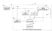
- FIG. 1 shows a block diagram of the over voltage protection testing apparatus of the present invention.
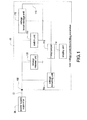
- FIG. 2 shows a block diagram of the voltage boost-storage unit of the present invention.
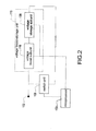
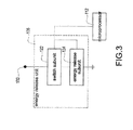
- FIG. 3 shows a block diagram of the energy release unit of the present invention.
- FIG. 1 shows a block diagram of the over voltage protection testing apparatus of the present invention.
- An over voltage protection testing apparatus 10 is applied to a power supply apparatus 20 .
- the power supply apparatus 20 is electrically connected to the over voltage protection testing apparatus 10 .
- the over voltage protection testing apparatus 10 includes a test contact 102 , a voltage detecting unit 104 , an energy release unit 106 , a switch unit 108 , a voltage boost-storage unit 110 , a microprocessor 112 , and a display unit 114 .
- the test contact 102 is electrically connected to the power supply apparatus 20 , the voltage detecting unit 104 , the energy release unit 106 , the switch unit 108 , and the voltage boost-storage unit 110 .
- the microprocessor 112 is electrically connected to the voltage detecting unit 104 , the energy release unit 106 , the switch unit 108 , the voltage boost-storage unit 110 , and the display unit 114 .
- the voltage boost-storage unit 110 is electrically connected to the switch unit 108 .
- FIG. 2 shows a block diagram of the voltage boost-storage unit of the present invention.
- the voltage boost-storage unit 110 includes a voltage boost subunit 118 and a voltage storage subunit 120 .
- the voltage boost subunit 118 is electrically connected to the test contact 102 and the microprocessor 112 .
- the voltage storage subunit 120 is electrically connected to the voltage boost subunit 118 , the microprocessor 112 , and the switch unit 108 .
- FIG. 3 shows a block diagram of the energy release unit of the present invention. Please refer to FIG. 1 and FIG. 2 as well.
- the energy release unit 106 includes a switch subunit 112 and an energy release subunit 124 .
- the switch subunit 122 is electrically connected to the test contact 102 and the microprocessor 112 .
- the energy release subunit 124 is electrically connected to the switch subunit 122 and the microprocessor 112 .
- a voltage output side of the power supply apparatus 20 is connected to the test contact 102 when the over voltage protection function of the power supply apparatus 20 is tested. Then, the power supply apparatus 20 is turned on. The power supply apparatus 20 outputs an original output voltage 22 (for example 12 volts) to the test contact 102 .
- the voltage detecting unit 104 is configured to detect the original output voltage 22 and inform the microprocessor 112 .
- the microprocessor 112 is configured to record a voltage value of the original output voltage 22 .
- the microprocessor 112 is configured to record that the voltage value of the original output voltage 22 is 12 volts.
- the voltage boost-storage unit 110 is used to boost the original output voltage 22 into a testing voltage 116 and store the testing voltage 116 .
- the voltage boost subunit 118 is used to boost the original output voltage 22 into the testing voltage 116 .
- the voltage storage subunit 120 is used to store the testing voltage 116 .
- the microprocessor 112 is configured to control the voltage storage subunit 120 to output the testing voltage 116 .
- the microprocessor 112 is configured to control the voltage boost subunit 118 to boost or reduce the testing voltage 116 .
- the microprocessor 112 is configured to control the energy release unit 106 and the switch unit 108 .
- the energy release unit 106 is not conducted when the switch unit 108 is conducted.
- the energy release unit 106 is conducted when the switch unit 108 is not conducted.
- the energy release unit 106 is conducted when the microprocessor 112 is configured to conduct the switch subunit 122 .
- the energy release unit 106 is not conducted when the microprocessor 112 is not configured to conduct the switch subunit 122 .
- the energy release subunit 124 is, for example but not limited to, a variable resistor circuit.
- the microprocessor 112 is configured to control a resistance value of the variable resistor circuit.
- the energy release subunit 124 could be a resistor as well.
- the power supply apparatus 0 receives the testing voltage 116 to test the over voltage protection function of the power supply apparatus 20 .
- the energy of an output side capacitor (not shown in FIG. 1 ) of the power supply apparatus 20 is released to the energy release unit 106 when the testing of the over voltage protection function of the power supply apparatus 20 is finished (the switch unit 108 is not conducted, and the energy release unit 106 is conducted).
- the energy release unit 106 is not conducted and the power supply apparatus 20 receives the testing voltage 116 when the switch unit 108 is conducted. Therefore, the over voltage protection function of the power supply apparatus 20 is tested.
- the power supply apparatus 20 is turned off when the testing voltage 116 is larger than a trigger voltage (for example 18 volts) of the over voltage protection function of the power supply apparatus 20 . Therefore, the power supply apparatus 20 stops outputting the original output voltage 22 to the test contact 102 . A voltage value of the test contact 102 is dropped to zero (the energy is released to the energy release unit 106 ).
- a trigger voltage for example 18 volts
- the power supply apparatus 20 is not turned off when the testing voltage 116 is not larger than the trigger voltage (for example 18 volts) of the over voltage protection function of the power supply apparatus 20 . Therefore, the power supply apparatus 20 continues to output the original output voltage 22 to the test contact 102 .
- the voltage value of the test contact 102 is boosted to the voltage value of the testing voltage 116 , and then dropped to the voltage value of the original output voltage 22 .
- the energy (resulted from the testing voltage 116 ) of the output side capacitor of the power supply apparatus 20 is released to the energy release unit 106 .
- the voltage detecting unit 104 is configured to detect the voltage of the test contact 102 and inform the microprocessor 112 .
- the microprocessor 112 is configured to judge whether the testing voltage 116 is large enough to trigger the over voltage protection function of the power supply apparatus 20 .
- the microprocessor 112 is informed that the power supply apparatus 20 is turned off due to the over voltage protection function when the voltage value (for example 12 volts) of the original output voltage 22 recorded in the microprocessor 112 minus the voltage value of the test contact 102 is larger than a predetermined value.
- the predetermined value is larger than zero and is any number (for example 3 volts).
- testing voltage 116 (for example 19 volts) is larger than the trigger voltage (for example 18 volts) of the over voltage protection function of the power supply apparatus 20 .
- the power supply apparatus 20 is turned off.
- the voltage detecting unit 104 detects that the voltage value of the test contact 102 is dropped to zero gradually.
- the microprocessor 112 is configured to control the voltage boost subunit 118 to boost the testing voltage 116 to find out the value of the trigger voltage of the over voltage protection function of the power supply apparatus 20 when the voltage value (for example 12 volts) of the original output voltage 22 recorded in the microprocessor 112 minus the voltage value of the test contact 102 is not larger than the predetermined value (the over voltage protection function of the power supply apparatus 20 is not yet triggered).
- the testing voltage 116 (for example 15 volts) is smaller than the trigger voltage (for example 18 volts) of the over voltage protection function of the power supply apparatus 20 .
- the power supply apparatus 20 is not turned off.
- the voltage value of the test contact 102 is dropped to the voltage value of the original output voltage 22 (for example 12 volts) gradually.
- the voltage detecting unit 104 detects that the voltage value of the test contact 102 is 12 volts.
- the microprocessor 112 is configured to control the voltage boost subunit 118 to boost the testing voltage 116 to find out the value of the trigger voltage of the over voltage protection function of the power supply apparatus 20 .
- the voltage value of the testing voltage 116 is changed increasingly (from small voltage to large voltage) in order to find out the value of the trigger voltage of the over voltage protection function of the power supply apparatus 20 .
- the display unit 114 is, for example but not limited to, a monitor.
- the display unit 114 is used to display information, such as the original output voltage 22 , the testing voltage 116 , the status of the power supply apparatus 20 (in working status or shutdown status due to over voltage protection), and so on.
- the voltage detecting unit 104 is, for example but not limited to, a voltage detecting circuit.
- the voltage boost subunit 118 is, for example but not limited to, a voltage boost circuit.
- the voltage storage subunit 120 is, for example but not limited to, a voltage storage circuit.
- the switch unit 108 is, for example but not limited to, a metal oxide semiconductor field effect transistor (MOSFET), an insulation gate bipolar transistor (IGBT), a silicon controlled rectifier (SCR), or a bipolar junction transistor (BJT).
- MOSFET metal oxide semiconductor field effect transistor
- IGBT insulation gate bipolar transistor
- SCR silicon controlled rectifier
- BJT bipolar junction transistor
- the switch subunit 122 is, for example but not limited to, a metal oxide semiconductor field effect transistor, an insulation gate bipolar transistor, a silicon controlled rectifier, or a bipolar junction transistor.
- the present invention includes following features.
- the voltage boost-storage unit 110 is used to boost the original output voltage 22 (outputted from the power supply apparatus 20 ) into the testing voltage 116 . Therefore, no extra testing voltage source is required for testing the over voltage protection function of the power supply apparatus 20 .
- the extra energy is released to the energy release unit 106 after the testing of the over voltage protection function of the power supply apparatus 20 is finished. Therefore, the extra energy is released faster and the efficiency of the testing is higher than the related art.
- the microprocessor 112 is configured to control the resistance value of the variable resistor circuit to control the time of the releasing energy.
- the circuit structure is simple and inexpensive.
Landscapes
- Physics & Mathematics (AREA)
- General Physics & Mathematics (AREA)
- Engineering & Computer Science (AREA)
- Power Engineering (AREA)
- General Engineering & Computer Science (AREA)
- Protection Of Static Devices (AREA)
Abstract
Description
- 1. Field of the Invention
- The present invention relates to a testing apparatus, and especially relates to an over voltage protection testing apparatus.
- 2. Description of the Related Art
- A power supply apparatus is a very common electronic apparatus. Besides supplying power, the power supply apparatus has many other functions, such as over voltage protection function.
- The over voltage protection function very important for the power supply apparatus. Therefore, testing the over voltage protection function of the power supply apparatus is also very important. Generally speaking, an over voltage protection testing apparatus is used for testing the over voltage protection function of the power supply apparatus.
- However, the over voltage protection testing apparatus of the related art includes following disadvantages.
- 1. An extra testing voltage source is required for testing the over voltage protection function of the power supply apparatus.
- 2. The extra energy is released slowly after the testing of the over voltage protection function of the power supply apparatus is finished.
- 3. The circuit structure is complicated and costly.
- In order to solve the above-mentioned problems, an object of the present invention is to provide an over voltage protection testing apparatus.
- In order to achieve the object of the present invention mentioned above, the over voltage protection testing apparatus of the present invention is applied to a power supply apparatus. The power supply apparatus is electrically connected to the over voltage protection testing apparatus. The over voltage protection testing apparatus includes a test contact, a voltage detecting unit, an energy release unit, a switch unit, a voltage boost-storage unit, and a microprocessor. The test contact is electrically connected to the power supply apparatus. The voltage detecting unit is electrically connected to the test contact. The energy release unit is electrically connected to the test contact. The switch unit is electrically connected to the test contact. The voltage boost-storage unit is electrically connected to the test contact and the switch unit. The microprocessor is electrically connected to the voltage detecting unit, the energy release unit, the switch unit, and the voltage boost-storage unit. The power supply apparatus outputs an original output voltage to the test contact. The voltage detecting unit is configured to detect the original output voltage and inform the microprocessor. The microprocessor is configured to record a voltage value of the original output voltage. The voltage boost-storage unit boosts the original output voltage into a testing voltage and stores the testing voltage. The microprocessor is configured to control the energy release unit and the switch unit. The energy release unit is not conducted and the power supply apparatus receives the testing voltage when the switch unit is conducted. Therefore, an over voltage protection function of the power supply apparatus is tested. The voltage detecting unit is configured to detect a voltage of the test contact and inform the microprocessor. The microprocessor is informed that the power supply apparatus is turned off due to the over voltage protection function when the voltage value of the original output voltage recorded in the microprocessor minus the voltage value of the test contact is larger than a predetermined value. The energy release unit is conducted and the power supply apparatus releases energy through the energy release unit when the switch unit is not conducted.
- Moreover, the voltage boost-storage unit includes a voltage boost subunit electrically connected to the test contact and the microprocessor. The voltage boost subunit is used to boost the original output voltage into the testing voltage. The microprocessor is configured to control the voltage boost subunit to boost the testing voltage when the voltage value of the original output voltage recorded in the microprocessor minus the voltage value of the test contact is not larger than the predetermined value.
- Moreover, the voltage boost-storage unit further includes a voltage storage subunit electrically connected to the voltage boost subunit, the microprocessor, and the switch unit. The voltage storage subunit is used to store the testing voltage. The microprocessor is configured to control the voltage storage subunit to output the testing voltage.
- Moreover, the energy release unit includes a switch subunit electrically connected to the test contact and the microprocessor. The energy release unit is conducted when the microprocessor is configured to conduct the switch subunit. The energy release unit is not conducted when the microprocessor is not configured to conduct the switch subunit.
- Moreover, the energy release unit further includes an energy release subunit electrically connected to the switch subunit and the microprocessor.
- Moreover, the energy release subunit is, for example but not limited to, a variable resistor circuit. The microprocessor is configured to control a resistance value of the variable resistor circuit.
- Moreover, the over voltage protection testing apparatus further includes a display unit electrically connected to the microprocessor.
- Moreover, the voltage detecting unit is, for example but not limited to, a voltage detecting circuit. The display unit is, for example but not limited to, a monitor. The voltage boost subunit is, for example but not limited to, a voltage boost circuit. The voltage storage subunit is, for example but not limited to, a voltage storage circuit.
- Moreover, the switch unit is, for example but not limited to, a metal oxide semiconductor field effect transistor (MOSFET), an insulation gate bipolar transistor (IGBT), a silicon controlled rectifier (SCR), or a bipolar junction transistor (JUT).
- Moreover, the switch subunit is, for example but not limited to, a metal oxide semiconductor field effect transistor, an insulation gate bipolar transistor, a silicon controlled rectifier, or a bipolar junction transistor.
-
FIG. 1 shows a block diagram of the over voltage protection testing apparatus of the present invention. -
FIG. 2 shows a block diagram of the voltage boost-storage unit of the present invention. -
FIG. 3 shows a block diagram of the energy release unit of the present invention. -
FIG. 1 shows a block diagram of the over voltage protection testing apparatus of the present invention. An over voltageprotection testing apparatus 10 is applied to apower supply apparatus 20. Thepower supply apparatus 20 is electrically connected to the over voltageprotection testing apparatus 10. - The over voltage
protection testing apparatus 10 includes atest contact 102, avoltage detecting unit 104, anenergy release unit 106, aswitch unit 108, a voltage boost-storage unit 110, amicroprocessor 112, and adisplay unit 114. - The
test contact 102 is electrically connected to thepower supply apparatus 20, thevoltage detecting unit 104, theenergy release unit 106, theswitch unit 108, and the voltage boost-storage unit 110. Themicroprocessor 112 is electrically connected to thevoltage detecting unit 104, theenergy release unit 106, theswitch unit 108, the voltage boost-storage unit 110, and thedisplay unit 114. The voltage boost-storage unit 110 is electrically connected to theswitch unit 108. -
FIG. 2 shows a block diagram of the voltage boost-storage unit of the present invention. The voltage boost-storage unit 110 includes avoltage boost subunit 118 and avoltage storage subunit 120. Thevoltage boost subunit 118 is electrically connected to thetest contact 102 and themicroprocessor 112. Thevoltage storage subunit 120 is electrically connected to thevoltage boost subunit 118, themicroprocessor 112, and theswitch unit 108. -
FIG. 3 shows a block diagram of the energy release unit of the present invention. Please refer toFIG. 1 andFIG. 2 as well. Theenergy release unit 106 includes aswitch subunit 112 and anenergy release subunit 124. Theswitch subunit 122 is electrically connected to thetest contact 102 and themicroprocessor 112. Theenergy release subunit 124 is electrically connected to theswitch subunit 122 and themicroprocessor 112. - A voltage output side of the
power supply apparatus 20 is connected to thetest contact 102 when the over voltage protection function of thepower supply apparatus 20 is tested. Then, thepower supply apparatus 20 is turned on. Thepower supply apparatus 20 outputs an original output voltage 22 (for example 12 volts) to thetest contact 102. - The
voltage detecting unit 104 is configured to detect theoriginal output voltage 22 and inform themicroprocessor 112. Themicroprocessor 112 is configured to record a voltage value of theoriginal output voltage 22. For example, themicroprocessor 112 is configured to record that the voltage value of theoriginal output voltage 22 is 12 volts. - The voltage boost-
storage unit 110 is used to boost theoriginal output voltage 22 into atesting voltage 116 and store thetesting voltage 116. - More specifically, the
voltage boost subunit 118 is used to boost theoriginal output voltage 22 into thetesting voltage 116. Thevoltage storage subunit 120 is used to store thetesting voltage 116. Themicroprocessor 112 is configured to control thevoltage storage subunit 120 to output thetesting voltage 116. Themicroprocessor 112 is configured to control thevoltage boost subunit 118 to boost or reduce thetesting voltage 116. - The
microprocessor 112 is configured to control theenergy release unit 106 and theswitch unit 108. Theenergy release unit 106 is not conducted when theswitch unit 108 is conducted. Theenergy release unit 106 is conducted when theswitch unit 108 is not conducted. - Moreover, the
energy release unit 106 is conducted when themicroprocessor 112 is configured to conduct theswitch subunit 122. Theenergy release unit 106 is not conducted when themicroprocessor 112 is not configured to conduct theswitch subunit 122. - The
energy release subunit 124 is, for example but not limited to, a variable resistor circuit. Themicroprocessor 112 is configured to control a resistance value of the variable resistor circuit. Theenergy release subunit 124 could be a resistor as well. - Therefore, the energy of the
testing voltage 116 is not released when the over voltage protection function of thepower supply apparatus 20 is tested (theswitch unit 108 is conducted, and theenergy release unit 106 is not conducted). The power supply apparatus 0 receives thetesting voltage 116 to test the over voltage protection function of thepower supply apparatus 20. - The energy of an output side capacitor (not shown in
FIG. 1 ) of thepower supply apparatus 20 is released to theenergy release unit 106 when the testing of the over voltage protection function of thepower supply apparatus 20 is finished (theswitch unit 108 is not conducted, and theenergy release unit 106 is conducted). - The
energy release unit 106 is not conducted and thepower supply apparatus 20 receives thetesting voltage 116 when theswitch unit 108 is conducted. Therefore, the over voltage protection function of thepower supply apparatus 20 is tested. - The
power supply apparatus 20 is turned off when thetesting voltage 116 is larger than a trigger voltage (for example 18 volts) of the over voltage protection function of thepower supply apparatus 20. Therefore, thepower supply apparatus 20 stops outputting theoriginal output voltage 22 to thetest contact 102. A voltage value of thetest contact 102 is dropped to zero (the energy is released to the energy release unit 106). - The
power supply apparatus 20 is not turned off when thetesting voltage 116 is not larger than the trigger voltage (for example 18 volts) of the over voltage protection function of thepower supply apparatus 20. Therefore, thepower supply apparatus 20 continues to output theoriginal output voltage 22 to thetest contact 102. The voltage value of thetest contact 102 is boosted to the voltage value of thetesting voltage 116, and then dropped to the voltage value of theoriginal output voltage 22. The energy (resulted from the testing voltage 116) of the output side capacitor of thepower supply apparatus 20 is released to theenergy release unit 106. - The
voltage detecting unit 104 is configured to detect the voltage of thetest contact 102 and inform themicroprocessor 112. Themicroprocessor 112 is configured to judge whether thetesting voltage 116 is large enough to trigger the over voltage protection function of thepower supply apparatus 20. - The
microprocessor 112 is informed that thepower supply apparatus 20 is turned off due to the over voltage protection function when the voltage value (for example 12 volts) of theoriginal output voltage 22 recorded in themicroprocessor 112 minus the voltage value of thetest contact 102 is larger than a predetermined value. The predetermined value is larger than zero and is any number (for example 3 volts). - For example, the testing voltage 116 (for example 19 volts) is larger than the trigger voltage (for example 18 volts) of the over voltage protection function of the
power supply apparatus 20. - The
power supply apparatus 20 is turned off. Thevoltage detecting unit 104 detects that the voltage value of thetest contact 102 is dropped to zero gradually. - The
microprocessor 112 is informed that thepower supply apparatus 20 is turned of due to the over voltage protection function when thevoltage detecting unit 104 detects that the voltage of thetest contact 102 is dropped to 9 volts (12−3=9). - The
microprocessor 112 is configured to control thevoltage boost subunit 118 to boost thetesting voltage 116 to find out the value of the trigger voltage of the over voltage protection function of thepower supply apparatus 20 when the voltage value (for example 12 volts) of theoriginal output voltage 22 recorded in themicroprocessor 112 minus the voltage value of thetest contact 102 is not larger than the predetermined value (the over voltage protection function of thepower supply apparatus 20 is not yet triggered). - For example, the testing voltage 116 (for example 15 volts) is smaller than the trigger voltage (for example 18 volts) of the over voltage protection function of the
power supply apparatus 20. Thepower supply apparatus 20 is not turned off. The voltage value of thetest contact 102 is dropped to the voltage value of the original output voltage 22 (for example 12 volts) gradually. Thevoltage detecting unit 104 detects that the voltage value of thetest contact 102 is 12 volts. Themicroprocessor 112 is configured to control thevoltage boost subunit 118 to boost thetesting voltage 116 to find out the value of the trigger voltage of the over voltage protection function of thepower supply apparatus 20. - Generally speaking, the voltage value of the
testing voltage 116 is changed increasingly (from small voltage to large voltage) in order to find out the value of the trigger voltage of the over voltage protection function of thepower supply apparatus 20. - Moreover, the
display unit 114 is, for example but not limited to, a monitor. Thedisplay unit 114 is used to display information, such as theoriginal output voltage 22, thetesting voltage 116, the status of the power supply apparatus 20 (in working status or shutdown status due to over voltage protection), and so on. - The
voltage detecting unit 104 is, for example but not limited to, a voltage detecting circuit. Thevoltage boost subunit 118 is, for example but not limited to, a voltage boost circuit. Thevoltage storage subunit 120 is, for example but not limited to, a voltage storage circuit. - The
switch unit 108 is, for example but not limited to, a metal oxide semiconductor field effect transistor (MOSFET), an insulation gate bipolar transistor (IGBT), a silicon controlled rectifier (SCR), or a bipolar junction transistor (BJT). - The
switch subunit 122 is, for example but not limited to, a metal oxide semiconductor field effect transistor, an insulation gate bipolar transistor, a silicon controlled rectifier, or a bipolar junction transistor. - The present invention includes following features.
- 1. The voltage boost-
storage unit 110 is used to boost the original output voltage 22 (outputted from the power supply apparatus 20) into thetesting voltage 116. Therefore, no extra testing voltage source is required for testing the over voltage protection function of thepower supply apparatus 20. - 2. The extra energy is released to the
energy release unit 106 after the testing of the over voltage protection function of thepower supply apparatus 20 is finished. Therefore, the extra energy is released faster and the efficiency of the testing is higher than the related art. Moreover, themicroprocessor 112 is configured to control the resistance value of the variable resistor circuit to control the time of the releasing energy. - 3. The circuit structure is simple and inexpensive.
- Although the present invention has been described with reference to the preferred embodiment thereof, it will be understood that the invention is not limited to the details thereof. Various substitutions and modifications have been suggested in the foregoing description, and others will occur to those of ordinary skill in the art. Therefore, all such substitutions and modifications are intended to be embraced within the scope of the invention as defined in the appended claims.
Claims (10)
Priority Applications (1)
| Application Number | Priority Date | Filing Date | Title |
|---|---|---|---|
| US13/875,776 US9030225B2 (en) | 2013-05-02 | 2013-05-02 | Over voltage protection testing apparatus |
Applications Claiming Priority (1)
| Application Number | Priority Date | Filing Date | Title |
|---|---|---|---|
| US13/875,776 US9030225B2 (en) | 2013-05-02 | 2013-05-02 | Over voltage protection testing apparatus |
Publications (2)
| Publication Number | Publication Date |
|---|---|
| US20140327466A1 true US20140327466A1 (en) | 2014-11-06 |
| US9030225B2 US9030225B2 (en) | 2015-05-12 |
Family
ID=51841135
Family Applications (1)
| Application Number | Title | Priority Date | Filing Date |
|---|---|---|---|
| US13/875,776 Active 2034-01-07 US9030225B2 (en) | 2013-05-02 | 2013-05-02 | Over voltage protection testing apparatus |
Country Status (1)
| Country | Link |
|---|---|
| US (1) | US9030225B2 (en) |
Cited By (6)
| Publication number | Priority date | Publication date | Assignee | Title |
|---|---|---|---|---|
| CN107957517A (en) * | 2016-10-17 | 2018-04-24 | 成都锐成芯微科技股份有限公司 | Power supply overvoltage spike detection circuit |
| CN108963968A (en) * | 2017-05-17 | 2018-12-07 | 卢昭正 | Short-circuit protection device for DC power supply |
| FR3075391A1 (en) * | 2017-12-18 | 2019-06-21 | Safran Electronics & Defense | CIRCUIT FOR MONITORING A LIGHTNING PROTECTION COMPONENT |
| CN111239514A (en) * | 2020-01-17 | 2020-06-05 | 苏州浪潮智能科技有限公司 | Method and device for testing overvoltage protection function of server power supply |
| US11105844B2 (en) * | 2019-06-28 | 2021-08-31 | Microsoft Technology Licensing, Llc | Predictive voltage transient reduction in integrated circuits |
| CN114252763A (en) * | 2021-11-29 | 2022-03-29 | 南方电网科学研究院有限责任公司 | Method and device for testing operation process of power module |
Families Citing this family (1)
| Publication number | Priority date | Publication date | Assignee | Title |
|---|---|---|---|---|
| ES2616122T3 (en) * | 2013-02-20 | 2017-06-09 | Omicron Electronics Gmbh | Procedure for checking various protection devices distributed in the space of a power supply network, as well as corresponding checking system |
Citations (4)
| Publication number | Priority date | Publication date | Assignee | Title |
|---|---|---|---|---|
| US7129759B2 (en) * | 2004-02-03 | 2006-10-31 | Nec Electronics Corporation | Integrated circuit including an overvoltage protection circuit |
| US20100226194A1 (en) * | 2007-07-20 | 2010-09-09 | He Huang | Power-failure protection circuit for non-volatile semiconductor storage devices and method for preventing unexpected power-failure using the same |
| US20130134985A1 (en) * | 2011-11-29 | 2013-05-30 | Infineon Technologies Austria Ag | System and Method for Testing a Power Supply Controller |
| US8933704B2 (en) * | 2012-03-26 | 2015-01-13 | Hong Fu Jin Precision Industry (Shenzhen) Co., Ltd. | Capacitive load testing device of power supply |
-
2013
- 2013-05-02 US US13/875,776 patent/US9030225B2/en active Active
Patent Citations (4)
| Publication number | Priority date | Publication date | Assignee | Title |
|---|---|---|---|---|
| US7129759B2 (en) * | 2004-02-03 | 2006-10-31 | Nec Electronics Corporation | Integrated circuit including an overvoltage protection circuit |
| US20100226194A1 (en) * | 2007-07-20 | 2010-09-09 | He Huang | Power-failure protection circuit for non-volatile semiconductor storage devices and method for preventing unexpected power-failure using the same |
| US20130134985A1 (en) * | 2011-11-29 | 2013-05-30 | Infineon Technologies Austria Ag | System and Method for Testing a Power Supply Controller |
| US8933704B2 (en) * | 2012-03-26 | 2015-01-13 | Hong Fu Jin Precision Industry (Shenzhen) Co., Ltd. | Capacitive load testing device of power supply |
Cited By (6)
| Publication number | Priority date | Publication date | Assignee | Title |
|---|---|---|---|---|
| CN107957517A (en) * | 2016-10-17 | 2018-04-24 | 成都锐成芯微科技股份有限公司 | Power supply overvoltage spike detection circuit |
| CN108963968A (en) * | 2017-05-17 | 2018-12-07 | 卢昭正 | Short-circuit protection device for DC power supply |
| FR3075391A1 (en) * | 2017-12-18 | 2019-06-21 | Safran Electronics & Defense | CIRCUIT FOR MONITORING A LIGHTNING PROTECTION COMPONENT |
| US11105844B2 (en) * | 2019-06-28 | 2021-08-31 | Microsoft Technology Licensing, Llc | Predictive voltage transient reduction in integrated circuits |
| CN111239514A (en) * | 2020-01-17 | 2020-06-05 | 苏州浪潮智能科技有限公司 | Method and device for testing overvoltage protection function of server power supply |
| CN114252763A (en) * | 2021-11-29 | 2022-03-29 | 南方电网科学研究院有限责任公司 | Method and device for testing operation process of power module |
Also Published As
| Publication number | Publication date |
|---|---|
| US9030225B2 (en) | 2015-05-12 |
Similar Documents
| Publication | Publication Date | Title |
|---|---|---|
| US9030225B2 (en) | Over voltage protection testing apparatus | |
| US9438049B2 (en) | Control circuit and method for a portable charging carrying case for providing uninterruptible power to charge electronic cigarette batteries | |
| US10033205B2 (en) | Power supply apparatus and method of providing power to an electronic device to prevent overcurrent discharge | |
| US20140368155A1 (en) | Smart vehicle rescue battery apparatus | |
| US20170346284A1 (en) | Power switch circuit and power circuit with the same | |
| US20150171655A1 (en) | Lithium battery auto-depassivation system and method | |
| US8780509B2 (en) | Circuit protection device and protection method | |
| EP2634883A2 (en) | Electronic device and protection circuit and protection method | |
| TWI590551B (en) | Electronic device and its charging protection circuit | |
| CN104065028A (en) | Electronic fuse device and method of operation thereof | |
| US20120126819A1 (en) | Detecting device and method for detecting battery storage capacity | |
| JP2014121169A (en) | Charge and discharge control circuit and battery device | |
| TW201339787A (en) | Communication terminal and control method thereof | |
| KR101707715B1 (en) | Power supply circuit and electronic device with power supply circuit | |
| CN104166299B (en) | Projector heat radiation method and apparatus | |
| CN105807878A (en) | An electronic apparatus power supply protection system | |
| CN105867574A (en) | Overvoltage protective device and method as well as server system | |
| TWI489735B (en) | Electronic equipment | |
| JP2011009152A5 (en) | ||
| TWI460454B (en) | Over voltage protection testing apparatus | |
| US20150054474A1 (en) | Power supply apparatus with reducing voltage overshooting | |
| CN105470913A (en) | Overvoltage protection circuit | |
| US9000830B2 (en) | Method and apparatus for protecting transistors | |
| US9531205B2 (en) | Alarm system for power supply | |
| TWI312925B (en) |
Legal Events
| Date | Code | Title | Description |
|---|---|---|---|
| AS | Assignment |
Owner name: CHICONY POWER TECHNOLOGY CO., LTD., TAIWAN Free format text: ASSIGNMENT OF ASSIGNORS INTEREST;ASSIGNORS:HUANG, CHIH-CHING;HUANG, JHEN-SIANG;HUANG, WEN-NAN;AND OTHERS;SIGNING DATES FROM 20130318 TO 20130319;REEL/FRAME:030346/0090 |
|
| STCF | Information on status: patent grant |
Free format text: PATENTED CASE |
|
| MAFP | Maintenance fee payment |
Free format text: PAYMENT OF MAINTENANCE FEE, 4TH YEAR, LARGE ENTITY (ORIGINAL EVENT CODE: M1551); ENTITY STATUS OF PATENT OWNER: LARGE ENTITY Year of fee payment: 4 |
|
| MAFP | Maintenance fee payment |
Free format text: PAYMENT OF MAINTENANCE FEE, 8TH YEAR, LARGE ENTITY (ORIGINAL EVENT CODE: M1552); ENTITY STATUS OF PATENT OWNER: LARGE ENTITY Year of fee payment: 8 |