US20140297160A1 - Shovel - Google Patents
Shovel Download PDFInfo
- Publication number
- US20140297160A1 US20140297160A1 US14/191,560 US201414191560A US2014297160A1 US 20140297160 A1 US20140297160 A1 US 20140297160A1 US 201414191560 A US201414191560 A US 201414191560A US 2014297160 A1 US2014297160 A1 US 2014297160A1
- Authority
- US
- United States
- Prior art keywords
- fuel efficiency
- display
- displayed
- shovel
- mode
- Prior art date
- Legal status (The legal status is an assumption and is not a legal conclusion. Google has not performed a legal analysis and makes no representation as to the accuracy of the status listed.)
- Granted
Links
- 239000000446 fuel Substances 0.000 claims abstract description 154
- 238000002485 combustion reaction Methods 0.000 claims abstract description 11
- 239000003086 colorant Substances 0.000 claims description 5
- 239000003990 capacitor Substances 0.000 description 61
- 238000004146 energy storage Methods 0.000 description 36
- 238000010586 diagram Methods 0.000 description 17
- 238000004891 communication Methods 0.000 description 8
- 230000001172 regenerating effect Effects 0.000 description 8
- 238000009434 installation Methods 0.000 description 6
- 230000005540 biological transmission Effects 0.000 description 5
- XLYOFNOQVPJJNP-UHFFFAOYSA-N water Substances O XLYOFNOQVPJJNP-UHFFFAOYSA-N 0.000 description 5
- 239000002828 fuel tank Substances 0.000 description 4
- 230000007246 mechanism Effects 0.000 description 4
- 238000002347 injection Methods 0.000 description 3
- 239000007924 injection Substances 0.000 description 3
- 230000004044 response Effects 0.000 description 3
- 239000011435 rock Substances 0.000 description 3
- 238000012546 transfer Methods 0.000 description 3
- 230000000007 visual effect Effects 0.000 description 3
- HBBGRARXTFLTSG-UHFFFAOYSA-N Lithium ion Chemical compound [Li+] HBBGRARXTFLTSG-UHFFFAOYSA-N 0.000 description 2
- 241000283973 Oryctolagus cuniculus Species 0.000 description 2
- 239000000498 cooling water Substances 0.000 description 2
- 238000013016 damping Methods 0.000 description 2
- 238000001514 detection method Methods 0.000 description 2
- 238000009499 grossing Methods 0.000 description 2
- 229910001416 lithium ion Inorganic materials 0.000 description 2
- 239000004065 semiconductor Substances 0.000 description 2
- 238000012935 Averaging Methods 0.000 description 1
- 241000270708 Testudinidae Species 0.000 description 1
- 230000004075 alteration Effects 0.000 description 1
- 230000008901 benefit Effects 0.000 description 1
- 238000004040 coloring Methods 0.000 description 1
- 238000010276 construction Methods 0.000 description 1
- 230000009365 direct transmission Effects 0.000 description 1
- 238000006073 displacement reaction Methods 0.000 description 1
- 238000005265 energy consumption Methods 0.000 description 1
- 230000005669 field effect Effects 0.000 description 1
- 229910044991 metal oxide Inorganic materials 0.000 description 1
- 150000004706 metal oxides Chemical class 0.000 description 1
- 230000008520 organization Effects 0.000 description 1
- 238000010248 power generation Methods 0.000 description 1
- 238000012545 processing Methods 0.000 description 1
- 238000012552 review Methods 0.000 description 1
- 238000006467 substitution reaction Methods 0.000 description 1
Images


Classifications
-
- E—FIXED CONSTRUCTIONS
- E02—HYDRAULIC ENGINEERING; FOUNDATIONS; SOIL SHIFTING
- E02F—DREDGING; SOIL-SHIFTING
- E02F9/00—Component parts of dredgers or soil-shifting machines, not restricted to one of the kinds covered by groups E02F3/00 - E02F7/00
- E02F9/26—Indicating devices
Definitions
- the present invention relates to shovels including a display unit that displays an operating condition.
- Shovels commonly have a display monitor provided in their cabins. By looking at a screen on the display monitor, it is possible for an operator of a shovel to check the operating condition of the shovel at the time.
- a construction machine has been proposed that includes a display part configured to perform such display as to make it possible to determine a difference between measured engine fuel efficiency and set engine fuel efficiency.
- a shovel includes a cabin in which a display monitor is provided, a main pump that generates a hydraulic pressure, an internal combustion engine that drives the main pump, and a display control part configured to generate display information to be displayed on the display monitor based on information communicated between the display control part and the internal combustion engine, and cause the generated display information to be displayed on the display monitor.
- the display control part is configured to cause a graph showing the fuel efficiency of the internal combustion engine over time and the operational work mode of the shovel corresponding to a time for which the fuel efficiency is calculated to be simultaneously displayed on the single display screen of the display monitor.
- FIG. 1 is a side view of a shovel according to an embodiment
- FIG. 2 is a block diagram illustrating a configuration of a drive system of the shovel illustrated in FIG. 1 according to an embodiment
- FIG. 3 is a circuit diagram of an electrical energy storage unit according to an embodiment
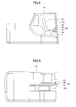
- FIG. 4 is a perspective view of a cabin, illustrating its interior, according to an embodiment
- FIG. 5 is a plan view of the cabin in which a display monitor is provided according to an embodiment
- FIG. 6 is a diagram illustrating a screen of the display monitor on which multiple graphs showing average fuel efficiency, to which information on a work mode is added, are displayed according to an embodiment
- FIG. 7 is a diagram illustrating a screen of the display monitor on which multiple graphs showing average actual engine operation fuel efficiency, to which information on a work mode is added, are displayed according to an embodiment
- FIG. 8 is a diagram illustrating a screen of the display monitor on which multiple graphs showing average actual lever operation fuel efficiency, to which information on a work mode is added, are displayed according to an embodiment
- FIG. 9 is a diagram illustrating a screen of the display monitor on which a graph showing a physical quantity of a turning electric motor and a graph showing the state of charge of a capacitor are simultaneously displayed in addition to multiple graphs showing average fuel efficiency, to which information on a work mode is added, according to an embodiment.
- a display unit displays a single content per screen.
- it is required to switch the screen of the display unit. Therefore, the operator is required to release her/his hand from an operation lever when the operator desires to switch the screen to display other content.
- the operator is impossible for the operator to release her/his hand from the operation lever. Therefore, it is impossible to switch the screen and thus to view desired content during shovel work.
- the operator monitors the basic condition of the shovel displayed on a basic screen and is prevented from viewing a screen that displays information on engine fuel efficiency, for example. Accordingly, it is impossible to provide the operator with information (content) regarding the fuel efficiency of the shovel while the operator is operating the shovel. Therefore, the operator is prevented from operating the shovel while considering engine fuel efficiency.
- a shovel is provided that is capable of providing an operator with information on the fuel efficiency of an engine without requiring the operator to operate a display unit during shovel work.
- FIG. 1 is a side view of a shovel according to an embodiment.
- the shovel illustrated in FIG. 1 is a hybrid shovel.
- Embodiments of the present invention may be applied to not only hybrid shovels but also any kinds of shovels as long as the shovels include an electrical energy storage device as a power supply for driving an electrical load.
- an upper-part turning body 3 (an upper-part turnable body) is mounted through a turning mechanism 2 on a lower-part traveling body 1 (a lower-part movable body) of the shovel.
- a boom 4 , an arm 5 , a bucket 6 , and a boom cylinder 7 , an arm cylinder 8 , and a bucket cylinder 9 for hydraulically driving the boom 4 , the arm 5 , and the bucket 6 , respectively, are provided on the upper-part turning body 3 .
- a cabin 10 and power sources are mounted on the upper-part turning body 3 .
- FIG. 2 is a block diagram illustrating a configuration of a drive system of the shovel illustrated in FIG. 1 according to an embodiment.
- a mechanical power system, a high-pressure hydraulic line, a pilot line, and an engine and electric drive and control system are indicated by a double line, a solid line, a broken line, and a dot-dash line, respectively.
- An engine 11 as a mechanical drive part and a motor generator 12 as an assist drive part are connected to a first input shaft and a second input shaft, respectively, of a transmission 13 .
- a main pump 14 and a pilot pump 15 are connected to the output shaft of the transmission 13 .
- a control valve 17 is connected to the main pump 14 via a high-pressure hydraulic line 16 .
- the control valve 17 is a control unit that controls a hydraulic system of the shovel. Hydraulic motors 1 A (right) and 1 B (left) for the lower-part traveling body 1 , the boom cylinder 7 , the arm cylinder 8 , and the bucket cylinder 9 are connected to the control valve 17 via high-pressure hydraulic lines.
- the electrical energy storage unit 120 includes a capacitor such as an electric double-layer capacitor (EDLC) as the electrical energy storage device.
- EDLC electric double-layer capacitor
- a turning electric motor 21 is connected to the electrical energy storage unit 120 via an inverter 20 .
- a capacitor is illustrated above as an example of the electrical energy storage device.
- a rechargeable battery which is chargeable and dischargeable, such as a lithium ion battery (LIB), or other form of power supply capable of transferring and receiving electric power may be used as the electrical energy storage device.
- LIB lithium ion battery
- a resolver 22 , a mechanical brake 23 , and a turning transmission 24 are connected to a rotating shaft 21 A of the turning electric motor 21 . Furthermore, an operation apparatus 26 is connected to the pilot pump 15 via a pilot line 25 .
- the control valve 17 and a pressure sensor 29 as a lever operation detecting part are connected to the operation apparatus 26 via hydraulic lines 27 and 28 , respectively.
- a controller 30 that controls the driving of an electric system is connected to the pressure sensor 29 .
- the inverter 18 is provided between the motor generator 12 and the electrical energy storage unit 120 .
- the inverter 18 controls the operation of the motor generator 12 based on commands from the controller 30 . This makes it possible for the inverter 18 to supply electric power from the electrical energy storage unit 120 to the motor generator 12 when the motor generator 12 performs a power running operation, and to store the electric power generated by the motor generator 12 in the electrical energy storage device of the electrical energy storage unit 120 when the motor generator 12 performs a regenerative operation.
- the electrical energy storage unit 120 is provided between the inverter 18 and the inverter 20 . This makes it possible for the electrical energy storage unit 120 to supply electric power for a power running operation when at least one of the motor generator 12 and the turning electric motor 21 performs a power running operation, and to store the electric power regenerated by a regenerative operation as electrical energy when at least one of the motor generator 12 and the turning electric motor 21 performs a regenerative operation.
- the inverter 20 is provided between the turning electric motor 21 and the electrical energy storage unit 120 .
- the inverter 20 controls the operation of the turning electric motor 21 based on commands from the controller 30 . This makes it possible for the inverter 20 to supply electric power from the electrical energy storage unit 120 to the turning electric motor 21 when the turning electric motor 21 performs a power running operation, and to store the electric power generated by the turning electric motor 21 in the electrical energy storage device of the electrical energy storage unit 120 when the turning electric motor 21 performs a regenerative operation.
- the charge and discharge of the electrical energy storage device of the electrical energy storage unit 120 is controlled by the controller 30 based on the state of charge of the electrical energy storage device, the operating state (power running operation or regenerative operation) of the motor generator 12 , and the operating state (power running operation or regenerative operation) of the turning electric motor 21 .
- the inverter 20 includes a current sensor 20 a and a voltage sensor 21 a.
- the controller 30 is a control unit serving as a main control part that controls the driving of the hybrid shovel.
- the controller 30 includes a processor including a central processing unit (CPU) and an internal memory 38 ( FIG. 2 ).
- the controller 30 is a device implemented by the CPU executing a drive control program contained in the internal memory 38 .
- the controller 30 converts a signal fed from the pressure sensor 29 into a speed command, and controls the driving of the turning electric motor 21 .
- the signal fed from the pressure sensor 29 corresponds to a signal that represents the amount of operation in the case of operating the operation apparatus 26 in order to cause the turning mechanism 2 to turn.
- the controller 30 controls the operation (switches the electric motor [assist] operation and the generator operation) of the motor generator 12 , and controls the charge and discharge of the electrical energy storage device by controlling the driving of a step-up/step-down converter 100 ( FIG. 3 ) of the electrical energy storage unit 120 .
- the controller 30 controls the charge and discharge of the electrical energy storage device by controlling the switching of the step-up operation and the step-down operation of the step-up/step-down converter 100 of the electrical energy storage unit 120 based on the state of charge of the electrical energy storage device, the operating state (electric motor [assist] operation or generator operation) of the motor generator 12 , and the operating state (power running operation or regenerative operation) of the turning electric motor 21 .
- the controller 30 also controls the amount of charging the electrical energy storage device (charging current or charging electric power) as described below.
- the controller 30 transmits or receives the water temperature of the cooling water of the engine 11 , a command value of the amount of fuel injection of the engine 11 , and the usage condition of an exhaust gas filter (DPF regenerator) through a communication circuit provided between the controller 30 and the engine 11 . Furthermore, the controller 30 receives the level of remaining fuel measured with a fuel gauge provided in a fuel tank 11 a through a communication circuit provided between the controller 30 and the fuel tank 11 a . Furthermore, the controller 30 receives information on the condition of settings of the shovel input from a setting input part (a display monitor 42 ) described below by an operator, through a communication circuit provided between the controller 30 and the setting input part.
- a setting input part a display monitor 42
- FIG. 3 is a circuit diagram of the electrical energy storage unit 120 according to an embodiment.
- the electrical energy storage unit 120 includes a capacitor 19 as an electrical energy storage device, the step-up/step-down converter 100 , and a DC bus 110 .
- the DC bus 110 controls the transfer of electric power among the capacitor 19 , the motor generator 12 , and the turning electric motor 21 .
- the capacitor 19 is provided with a capacitor voltage detecting part 112 for detecting a capacitor voltage value and a capacitor current detecting part 113 for detecting a capacitor current value.
- the capacitor voltage value detected by the capacitor voltage detecting part 112 and the capacitor current value detected by the capacitor current detecting part 113 are fed to the controller 30 .
- the step-up/step-down converter 100 performs such control as the switching of a step-up operation and a step-down operation in accordance with the operating states of the motor generator 12 and the turning electric motor 21 , so that the DC bus voltage value falls within a certain range.
- the DC bus 110 is provided between the inverters 18 and 20 and the step-up/step-down converter 100 to transfer electric power among the capacitor 19 , the motor generator 12 , and the turning electric motor 21 .
- the switching of the step-up operation and the step-down operation of the step-up/step-down converter 100 is controlled based on the DC bus voltage value detected by a DC bus voltage detecting part 111 , the capacitor voltage value detected by the capacitor voltage detecting part 112 , and the capacitor current value detected by the capacitor current detecting part 113 .
- the electric power generated by the motor generator 12 which is an assist motor, is supplied to the DC bus 110 of the electrical energy storage unit 120 via the inverter 18 to be supplied to the capacitor 19 via the step-up/step-down converter 100 .
- the electric power regenerated by the regenerative operation of the turning electric motor 21 is supplied to the DC bus 110 of the electrical energy storage unit 120 via the inverter 20 to be supplied to the capacitor 19 via the step-up/step-down converter 100 .
- the step-up/step-down converter 100 includes a reactor 101 , a step-up IGBT (Insulated Gate Bipolar Transistor) 102 A, a step-down IGBT 102 B, power supply connection terminals 104 for connecting the capacitor 19 , and output terminals 106 for connecting the inverters 18 and 20 .
- the output terminals 106 of the step-up/step-down converter 100 and the inverters 18 and 20 are connected by the DC bus 110 .
- the reactor 101 has one end connected to a point between the step-up IGBT 102 A and the step-down IGBT 102 B and has the other end connected to one of the power supply connection terminals 104 .
- the reactor 101 is provided to supply the DC bus 110 with the induced electromotive power generated with the turning-on/off of the step-up IGBT 102 A.
- the step-up IGBT 102 A and the step-down IGBT 1028 which are constituted of bipolar transistors each having a MOSFET (Metal Oxide Semiconductor Field Effect Transistor) incorporated into its gate part, are semiconductor devices (switching elements) capable of high-speed switching with high power.
- the step-up IGBT 102 A and the step-down IGBT 102 B are driven by application of PWM voltage to their gate terminals by the controller 30 .
- Diodes 102 a and 102 b which are rectifying elements, are connected in parallel to the step-up IGBT 102 A and the step-down IGBT 102 B, respectively.
- the capacitor 19 may be a chargeable and dischargeable electrical energy storage device so as to enable transfer of electric power to and from the DC bus 110 via the step-up/step-down converter 100 .
- the capacitor 19 is illustrated as an electrical energy storage device.
- a rechargeable battery which is chargeable and dischargeable, such as a lithium ion battery, or other form of power supply capable of transferring and receiving electric power may be used.
- the power supply connection terminals 104 may be terminals to which the capacitor 19 may be connected, and the output terminals 106 may be terminals to which the inverters 18 and 20 may be connected.
- the capacitor voltage detecting part 112 that detects the capacitor voltage is connected between the paired power supply connection terminals 104 .
- the DC bus voltage detecting part 111 that detects the DC bus voltage is connected between the paired output terminals 106 .
- the capacitor voltage detecting part 112 detects the voltage value Vcap of the capacitor 19 .
- the DC bus voltage detecting part 111 detects the voltage value Vdc of the DC bus 110 .
- a smoothing capacitor 107 is an electrical energy storage element inserted between the positive and the negative output terminal 106 to smooth the DC bus voltage. The voltage of the DC bus 110 is maintained at a predetermined voltage by this smoothing capacitor 107 .
- the capacitor current detecting part 113 is a detecting part that detects the value of an electric current flowing through the capacitor 19 on the positive terminal (P terminal) side of the capacitor 19 . That is, the capacitor current detecting part 113 detects the value of an electric current I 1 that flows through the positive terminal of the capacitor 19 .
- step-up/step-down converter 100 at the time of raising the voltage of the DC bus 110 , a PWM voltage is applied to the gate terminal of the step-up IGBT 102 A, so that the induced electromotive force generated in the reactor 101 with the turning-on/off of the step-up IGBT 102 A is supplied to the DC bus 110 via the diode 102 b connected in parallel to the step-down IGBT 102 B. As a result, the voltage of the DC bus 110 is raised.
- a PWM voltage is applied to the gate terminal of the step-down IGBT 102 B, so that regenerated electric power supplied via the inverter 18 or 20 is supplied from the DC bus 110 to the capacitor 19 via the step-down IGBT 102 B.
- the capacitor 19 is charged with the electric power stored in the DC bus 110 , so that the voltage of the DC bus 110 is lowered.
- a relay 130 - 1 is provided as a breaker capable of breaking the power supply line 114 .
- the relay 130 - 1 is placed between a connecting point 115 , where the capacitor voltage detecting part 112 is connected to the power supply line 114 , and the positive terminal of the capacitor 19 .
- the relay 130 - 1 is caused to operate by a signal from the controller 30 , and is capable of disconnecting the capacitor 19 from the step-up/step-down converter 100 by breaking the power supply line 114 from the capacitor 19 .
- a relay 130 - 2 is provided as a breaker capable of breaking the power supply line 117 .
- the relay 130 - 2 is placed between a connecting point 118 , where the capacitor voltage detecting part 112 is connected to the power supply line 117 , and the negative terminal of the capacitor 19 .
- the relay 130 - 2 is caused to operate by a signal from the controller 30 , and is capable of disconnecting the capacitor 19 from the step-up/step-down converter 100 by breaking the power supply line 117 from the capacitor 19 .
- the capacitor 19 may be disconnected by breaking both the power supply line 114 on the positive terminal side and the power supply line 117 on the negative terminal side simultaneously, forming the relay 130 - 1 and the relay 130 - 2 as a single relay.
- a drive part that generates PWM signals to drive the step-up IGBT 102 A and the step-down IGBT 102 B between the controller 30 and the step-up IGBT 102 A and the step-down IGBT 102 B.
- the drive part is omitted.
- Such a drive part may be implemented by either an electronic circuit or a processor.
- FIG. 4 is a side view of the cabin 10 , illustrating its interior, according to an embodiment.
- FIG. 5 is a plan view of the cabin 10 , in which a display monitor is provided, according to an embodiment.
- An operator's seat 40 is provided inside the cabin 10 , and the display monitor 42 is placed near the operator's seat 40 . It is possible for an operator seated on the operator's seat 40 to understand the state of each part of the shovel by viewing the display monitor 42 while operating operation levers 26 A and 26 B ( FIG. 2 ). As described below, various kinds of information (contents) are displayed on the display monitor 42 by a display control part 70 ( FIG. 1 ).
- An attachment part 50 for attaching the display monitor 42 includes an installation base 52 and a mount part 54 supported by the installation base 52 .
- the installation base 52 is attached and fixed to a frame 10 a of the cabin 10 , in which the operator's seat 40 is provided.
- the mount part 54 is supported on the installation base 52 through a damping mechanism 56 , which includes an elastic body such as a spring or rubber, so as to prevent direct transmission of vibrations of or impact on the cabin 10 to the mount part 54 via the installation base 52 . That is, the mount part 54 is supported on the installation base 52 through the damping mechanism 56 , so that vibrations of or impact on the cabin 10 transmitted to the display monitor 42 fixed to the mount part 54 is reduced.
- the boom 4 is disposed on the right side as viewed from the operator seated on the operator's seat 40 , and the operator often operates the shovel while viewing the arm 5 attached to the end of the boom 4 or the bucket 6 attached to the arm 5 .
- the frame 10 a which is on the front right side of the cabin 10 , is a part that obstructs the operator's view.
- the attachment part 50 of the display monitor 42 is provided using this part.
- the display monitor 42 is placed on the part that is an obstruction to the view from the beginning, the display monitor 42 does not itself obstruct the operator's view.
- a display unit such as an LCD touchscreen panel is employed as the display monitor 42 .
- a portable terminal (a multifunction portable information terminal) may be used as a display unit.
- a display unit 80 includes the display control part 70 included in the controller 30 and the display monitor 42 provided inside the cabin 10 .
- the display control part 70 is a functional element that is implemented by the CPU of the controller 30 executing a display control program contained in the internal memory 38 .
- the display control part 70 of the controller 30 includes a display data generation part 72 and a display data transmission part 74 .
- the display data generation part 72 creates display data that are displayed on the display monitor 42 based on detection values from various sensors (detectors) transmitted to the controller 30 and stored information (data).
- the detection values and the stored information include the above-described water temperature of the cooling water of the engine 11 , command value of the amount of fuel injection of the engine 11 , and usage condition of an exhaust gas filter (DPF regenerator) that the controller 30 transmits or receives through the communication circuit provided between the controller 30 and the engine 11 .
- the display data generation part 72 stores created display data in the internal memory 38 of the controller 30 .
- the display data transmission part 74 reads display data stored in the internal memory 38 and suitably transmits the read display data to the display monitor 42 .
- the display monitor 42 In response to reception of the display data, the display monitor 42 displays a screen based on the display data. It is possible for the operator to obtain various kinds of information including the condition of the shovel by viewing the screen of the display monitor 42 .
- the display monitor 42 also operates as a setting input part.
- an LCD touchscreen panel or the like is employed as the display monitor 42 , and info/oration regarding the condition of settings (setting condition) of the shovel, such as a work mode, may be input from the display monitor 42 by the operator.
- the display monitor 42 also operates as a setting input part.
- a setting input part may be provided separately from the display monitor 42 .
- a touchscreen panel that also operates as a setting input part and a setting input part provided separately from the touchscreen panel may be combined, so that different setting input parts may be used depending on the contents of settings.
- FIG. 6 is a diagram illustrating a screen of the display monitor 42 on which multiple graphs showing average fuel efficiency are displayed.
- the water temperature of the engine 11 is displayed on a multilevel scale in a region 201 along the left side. Furthermore, the remaining amount of fuel stored in the fuel tank 11 a is displayed on a multilevel scale in a region 202 along the right side.
- the engine water temperature and the remaining amount of fuel which are information items to be constantly observed by the operator, correspond to information on the operating condition of the shovel.
- the water temperature of the engine 11 displayed in the region 201 is information obtained from the engine 11 via the above-described communication circuit by the controller 30 . Furthermore, the remaining amount of fuel displayed in the region 202 is information obtained from the fuel gauge of the fuel tank 11 a via the above-described communication circuit by the controller 30 .
- a work mode that is currently set for the shovel is displayed in a region 203 at the left end of a region along the upper side of the display screen 200 .
- the work mode is input from the setting input part (the display monitor 42 ) by the operator.
- the work mode is a mode for limiting the output of the shovel.
- one of an automatic mode “A,” a heavy mode “H,” and a superpower mode “SP” is set as the work mode.
- the automatic mode “A” is a power save mode, in which the shovel is operated in such a manner as to reduce engine fuel consumption.
- the heavy mode “H” is a mode to increase engine output to make it possible to do heavy work.
- the superpower mode “SP” is a mode for temporarily exerting a large work force by further increasing engine output from that of the heavy mode “H.”
- “A” is displayed, so that it is possible for the operator to recognize that the power save mode is set.
- a traveling mode is displayed as the setting mode of traveling hydraulic motors using a variable displacement pump.
- the traveling mode includes a low-speed mode and a high-speed mode.
- the low-speed mode is displayed using a mark (schematic diagram) in the shape of a “tortoise” and the high-speed mode is displayed with a mark (schematic diagram) in the shape of a “rabbit.”
- the mark (schematic diagram) in the shape of a “rabbit” is displayed, so that it is possible for the operator to recognize that the high-speed mode is set.
- the stopped/operating state of the engine 11 is displayed in a region 205 on the right side next to the region 204 , where the traveling mode is displayed.
- “STOP” is displayed to indicate that the engine 11 is stopped.
- the current time is displayed in a region 206 at the right end of the region along the upper side of the display screen 200 . In the case illustrated in FIG. 6 , it is indicated that the current time is 9:25.
- a currently attached attachment is displayed.
- Attachments attachable to the shovel include various attachments such as a bucket, a rock drill, a grapple, and a lifting magnet.
- marks (schematic diagrams) in the shape of these attachments and numbers corresponding to the attachments are displayed.
- a mark (schematic diagram) in the shape of a rock drill is displayed, and “3” is displayed as a number indicating the magnitude of the output of the rock drill.
- Other information may be displayed in a region between the region 205 and the region 207 .
- the name of a manufacturer of the shovel may be displayed as other information.
- the information displayed in the above-described regions 203 , 204 , 205 , and 207 is information input from the setting input part (display monitor 42 ) and obtained by the controller 30 via the above-described communication circuit.
- a region 208 under the region 204 and the region 205 the operating time of an exhaust gas filter is displayed. Furthermore, in an upper part of the region 208 , a setting as to whether to remove captured matter automatically or manually is displayed.
- the operating time of an exhaust gas filter and so on displayed in the region 208 are information items obtained from the engine 11 via the above-described communication circuit by the controller 30 .
- a load applied to the end of the arm 5 is numerically displayed.
- the load applied to the end of the arm 5 displayed in the region 209 is information obtained from a hydraulic sensor (not illustrated) by the controller 30 .
- the above-described information displayed in the regions 201 through 209 indicates the operating condition and the setting condition of the shovel. That is, the information displayed in the regions 201 , 202 , 208 , and 209 is information on the operating condition of the shovel, and the information displayed in the regions 203 , 204 , 205 , and 207 is information on the setting condition of the shovel.
- the information on the operating condition and the setting condition of the shovel is standard information displayed on the display screen 200 .
- additional information other than the above-described display information is displayed in a region 210 .
- multiple graphs two graphs in this embodiment
- the two graphs are displayed one above the other on the screen.
- An upper graph is a bar graph 260 that shows the hour-by-hour average fuel efficiency of the past 12 hours.
- a lower graph is a bar graph 262 that shows the day-by-day average fuel efficiency of the past 7 days.
- the upper graph and the lower graph which are both graphs that show average fuel efficiency, have different time axes, so that the upper graph has a time axis of an interval of the past 12 hours and shows the hour-by-hour average fuel efficiency, while the lower graph has a time axis of an interval of the past 7 days and shows the day-by-day average fuel efficiency.
- the average fuel efficiency is determined based on a command value of the amount of fuel injection transmitted from the controller 30 to the engine 11 .
- the hour-by-hour average fuel efficiency is represented by vertical bars (extending toward the upper side of the screen) on the screen. Accordingly, 12 bars representing the average fuel efficiency are displayed in the bar graph 260 that shows the average fuel efficiency of the past 12 hours.
- a bar that represents the average fuel efficiency of the last 1 hour is displayed differently from the other bars. Specifically, the luminance of the bar representing the average fuel efficiency of the last 1 hour is caused to be higher than the luminance of the other bars, or the bar representing the average fuel efficiency of the last 1 hour is displayed in a color different from the color of the other bars. This facilitates visual recognition of the average fuel efficiency of the last 1 hour.
- “NOW” is displayed below the bar representing the average fuel efficiency of the last 1 hour, thus making it easy to visually recognize that the bar is the average fuel efficiency of the last 1 hour (that is, a current average fuel efficiency).
- “6 HOURS AGO” is displayed below a bar that represents the average fuel efficiency between 5 hours ago and 6 hours ago
- “12 HOURS AGO” is displayed below a bar that represents the average fuel efficiency between 11 hours ago and 12 hours ago.
- the day-by-day average fuel efficiency is represented by vertical bars (extending toward the upper side of the screen) on the screen. Accordingly, seven bars representing the average fuel efficiency are displayed in the bar graph 262 that shows the average fuel efficiency of the past 7 days. Of the bars, a bar that represents the average fuel efficiency of the last 1 day is displayed differently from the other bars.
- the luminance of the bar representing the average fuel efficiency of the last 1 day is caused to be higher than the luminance of the other bars, or the bar representing the average fuel efficiency of the last 1 day is displayed in a color different from the color of the other bars. This facilitates visual recognition of the average fuel efficiency of the last 1 day.
- “NOW” is displayed below the bar representing the daily average fuel efficiency between now and 1 day ago, thus making it easy to visually recognize that the bar is the average fuel efficiency of the last 1 day (that is, a current average fuel efficiency).
- “4 DAYS AGO” is displayed below a bar that represents the daily average fuel efficiency between 3 days ago and 4 days ago
- “7 DAYS AGO” is displayed below a bar that represents the daily average fuel efficiency between 6 days ago and 7 days ago.
- no bar is displayed in a part for showing the average fuel efficiency of “4 DAYS AGO.” This indicates that the shovel was not in operation “4 DAYS AGO.” For example, no bar is thus displayed that represents the average fuel efficiency in the case where it was a Sunday “4 DAYS AGO” and there was no shovel work because of a holiday.
- the operational work mode (also simply referred to as “work mode”) of the shovel includes multiple work modes.
- one of the superpower mode (SP mode), the heavy mode (H mode), and the automatic mode (A mode) may be set as the operational work mode of the shovel.
- the shovel operator selects a work mode to be used and sets the work mode via the operation part of the shovel.
- the SP mode is a work mode for performing work by setting the output of the engine 11 to a higher level so as to make it possible to temporarily accommodate a large load.
- the rotational speed of the engine 11 is set to be higher than usual, for example, to 1800 rpm.
- the output of the main pump 14 also is set to be higher.
- the H mode is a work mode that is set when performing normal work.
- the rotational speed of the engine 11 is set to a value lower than the rotational speed at the time of the SP mode, for example, 1700 rpm.
- the A mode which is also called “eco mode,” is a work mode to reduce energy consumption (the amount of fuel consumed by the engine 11 ) by reducing output compared with the H mode that is usually set.
- the rotational speed of the engine 11 is set to a value lower than the rotational speed at the time of the H mode, for example, 1600 rpm.
- the operator determines which work mode to use based on the contents of work and sets the determined work mode. In the case of normal work, the operator selects and sets the H mode. In the case of work that is heavier than usual and requires high power, the operator selects and sets the SP mode. If it is desired to perform work with a reduced amount of fuel consumption, the operator selects and sets the A mode.
- display is performed so as to facilitate visually recognizing a work mode corresponding to a time for which the average fuel efficiency is shown, that is, which work mode is set in a time for which the average fuel efficiency is shown. That is, the work modes are assigned respective predetermined colors, and the bars of graphical display showing the average fuel efficiency are colored with the colors assigned to the work modes. As a result, by looking at the color of a bar of the graph showing the average fuel efficiency, it is possible to easily understand what work mode was set in a time (for example, 6 hours ago or 3 days ago) corresponding to the bar.
- the SP mode is assigned red
- the H mode is assigned yellow
- the A mode is assigned blue.
- the work mode set in a time corresponding to the bar of the average fuel efficiency of 6 hours ago is the SP mode.
- the bar of the average fuel efficiency of 6 hours ago is displayed in red assigned to the SP mode.
- the work mode set in a time corresponding to the bar of the average fuel efficiency of 1 day ago is the SP mode.
- the bar of the average fuel efficiency of 1 day ago is displayed in red assigned to the SP mode.
- the bar of the average fuel efficiency of 2 hours ago is displayed in blue assigned to the A mode.
- no bar is displayed in blue in the graph showing the fuel efficiency averaged on a daily basis (the lower graph).
- the A mode has been set in no time.
- the set work mode may be switched to another mode within the unit time.
- the bar display of average fuel efficiency is performed by selecting a color assigned to a dominant work mode in the unit time.
- the term “dominant” means that the work mode is set for a longer time than other work modes.
- the SP mode was set for 45 minutes and the H mode was set for the remaining 15 minutes.
- the SP mode was set for a longer time than the H mode. Therefore, in this case, the SP mode is regarded as a dominant work mode, and the bar showing the average fuel efficiency of 6 hours ago is displayed in red assigned to the SP mode.
- all of the SP mode, the H mode, and the A mode may be set within the unit time.
- a work mode set for the longest time is regarded as a dominant work mode, and the bar is displayed in a color assigned to the work mode.
- coloring the bars of a graph showing average fuel efficiency and indicating work modes set at the times remind the operator of, for example, a work mode at the time of good average fuel efficiency, thus triggering a review of a currently set work mode by the operator. That is, by displaying information on the work mode in a graph showing average fuel efficiency, it is possible to encourage the operator to set a work mode that improves fuel efficiency.
- the bar graph 260 that shows the average fuel efficiency of the past 12 hours and the bar graph 262 that shows the average fuel efficiency of the past 7 days are simultaneously displayed on a single screen. Therefore, it is possible for the shovel operator to go back to 12 hours ago to 7 days ago to determine whether the fuel efficiency in current work due to her/his lever operation is better or worse than the fuel efficiency in the past work. Then, for example, if the current work is similar to the work of 5 days ago, the operator may compare the fuel efficiency of 5 days ago and current fuel efficiency and control the lever operation in the current work so that the lever operation in the current work comes closer to a lever operation in the work of 5 days ago. For example, if the fuel efficiency in the current work is worse than the fuel efficiency of 5 days ago, it is possible for the operator to improve the fuel efficiency in the current work by recalling and approximating the lever operation of 5 days ago.
- FIG. 6 the average fuel efficiency is graphically displayed.
- average actual engine operation fuel efficiency may be graphically displayed.
- FIG. 7 is a diagram illustrating a screen of the display monitor 42 on which two graphs of average actual engine operation fuel efficiency having different time axes are displayed in the same manner as in the case illustrated in FIG. 6 . That is, on a display screen 300 illustrated in FIG. 7 , the bar graphs 260 and 262 of average fuel efficiency illustrated in FIG. 6 are replaced with bar graphs 270 and 272 , respectively, of average actual engine operation fuel efficiency, but the contents of display are otherwise the same as those illustrated in FIG. 6 .
- the average actual engine operation fuel efficiency is the fuel efficiency of the engine 11 averaged based solely on time during which the shovel is in operation, that is, the engine 11 of the shovel is in operation.
- the fuel efficiency is averaged by time including time during which the shovel is not in operation, that is, the engine 11 is stopped, so that the average fuel efficiency varies in response to variations in the time during which the engine 11 is stopped.
- the average actual engine operation fuel efficiency which is the fuel efficiency of the engine 11 of the shovel averaged based solely on the time during which the engine 11 is in operation, is graphically displayed. As a result, such variations in the average fuel efficiency are removed, so that more accurate average fuel efficiency is displayed.
- FIG. 8 is a diagram illustrating a screen of the display monitor 42 on which two graphs of average actual lever operation fuel efficiency having different time axes are displayed in the same manner as in the case illustrated in FIG. 6 . That is, on a display screen 400 illustrated in FIG. 8 , the bar graphs 260 and 262 of average fuel efficiency illustrated in FIG. 6 are replaced with bar graphs 280 and 282 , respectively, of average actual lever operation fuel efficiency, but the contents of display are otherwise the same as those illustrated in FIG. 6 .
- the average actual lever operation fuel efficiency is the fuel efficiency of the engine 11 averaged based solely on time during which the shovel is working, that is, the operator is operating a lever (for example, the operation lever 26 A or 26 B in FIG. 2 ).
- the fuel efficiency is averaged by time including time during which the engine 11 is running idle with no work performed, so that the average fuel efficiency varies in response to variations in the time during which the engine 11 is running idle.
- the average actual lever operation fuel efficiency which is the fuel efficiency of the engine 11 of the shovel averaged based solely on the time during which a lever of the shovel is being operated, is graphically displayed. As a result, such variations in the average actual engine operation fuel efficiency are removed, so that more accurate average fuel efficiency is displayed.
- FIG. 9 is a diagram illustrating a screen of the display monitor 42 on which a graph showing a physical quantity of the turning electric motor 21 is simultaneously displayed in addition to two graphs showing average fuel efficiency.
- the output of the turning electric motor 21 is determined based on the current value detected from the current sensor 20 a of the inverter 20 or based on the current value and the voltage value detected from both the current sensor 20 a and the voltage sensor 20 b of the inverter 20 . Furthermore, the state of charge of the capacitor 19 is determined based on the voltage value detected in the capacitor voltage detecting part 112 .
- the above-described graphical display of the output of the turning electric motor 21 allows the operator to instantaneously visually understand how much electric power is consumed or how much electric power is generated by a turning operation currently performed. This makes it possible for the operator to, for example, determine the appropriateness of the operator's turning operation in light of energy saving and to learn an appropriate turning lever operation in light of energy saving. Furthermore, graphically displaying the state of charge of the capacitor 19 makes it possible for the operator to check the state of charge of the capacitor 19 substantially simultaneously while checking basic information. Thus, the convenience of the display unit 80 is increased. Furthermore, there is no need to switch the display screen to check the state of charge of the capacitor 19 , and it is possible to check the state of charge while operating an operation lever.
- displaying the state of charge of the capacitor 19 beside the output display of the turning electric motor 21 on the same screen makes it possible for the operator to, for example, try to positively perform such a turning lever operation as to enable power generation when the state of charge is low. Furthermore, it is possible for the operator to see how the state of charge changes in the case of continuing the operator's turning operation while viewing a single display screen. Thus, the convenience of the display unit 80 is increased.
- a simultaneous display of a graph showing average fuel efficiency, a graph showing the output of the electric turning motor 21 , and a graph showing the state of charge of the capacitor 19 on a single screen makes it possible for the shovel operator to instantaneously obtain these information items without releasing her/his hand from an operation lever to perform an operation to switch a screen.
- the convenience of the display unit 80 is increased.
- the bar graphs 260 and 262 may be replaced with the bar graphs 270 and 272 illustrated in FIG. 7 or the bar graphs 280 and 282 illustrated in FIG. 8 .
Landscapes
- Engineering & Computer Science (AREA)
- Mining & Mineral Resources (AREA)
- Civil Engineering (AREA)
- General Engineering & Computer Science (AREA)
- Structural Engineering (AREA)
- Component Parts Of Construction Machinery (AREA)
- Instrument Panels (AREA)
Abstract
Description
- This application is based upon and claims the benefit of priority of Japanese Patent Application No. 2013-067626, filed on Mar. 27, 2013, the entire contents of which are incorporated herein by reference.
- 1. Technical Field
- The present invention relates to shovels including a display unit that displays an operating condition.
- 2. Description of Related Art
- Shovels commonly have a display monitor provided in their cabins. By looking at a screen on the display monitor, it is possible for an operator of a shovel to check the operating condition of the shovel at the time. For example, a construction machine has been proposed that includes a display part configured to perform such display as to make it possible to determine a difference between measured engine fuel efficiency and set engine fuel efficiency.
- According to an aspect of the present invention, a shovel includes a cabin in which a display monitor is provided, a main pump that generates a hydraulic pressure, an internal combustion engine that drives the main pump, and a display control part configured to generate display information to be displayed on the display monitor based on information communicated between the display control part and the internal combustion engine, and cause the generated display information to be displayed on the display monitor. The display control part is configured to cause a graph showing the fuel efficiency of the internal combustion engine over time and the operational work mode of the shovel corresponding to a time for which the fuel efficiency is calculated to be simultaneously displayed on the single display screen of the display monitor.
- It is to be understood that both the foregoing general description and the following detailed description are exemplary and explanatory and not restrictive of the invention.
-
FIG. 1 is a side view of a shovel according to an embodiment; -
FIG. 2 is a block diagram illustrating a configuration of a drive system of the shovel illustrated inFIG. 1 according to an embodiment; -
FIG. 3 is a circuit diagram of an electrical energy storage unit according to an embodiment; -
FIG. 4 is a perspective view of a cabin, illustrating its interior, according to an embodiment; -
FIG. 5 is a plan view of the cabin in which a display monitor is provided according to an embodiment; -
FIG. 6 is a diagram illustrating a screen of the display monitor on which multiple graphs showing average fuel efficiency, to which information on a work mode is added, are displayed according to an embodiment; -
FIG. 7 is a diagram illustrating a screen of the display monitor on which multiple graphs showing average actual engine operation fuel efficiency, to which information on a work mode is added, are displayed according to an embodiment; -
FIG. 8 is a diagram illustrating a screen of the display monitor on which multiple graphs showing average actual lever operation fuel efficiency, to which information on a work mode is added, are displayed according to an embodiment; and -
FIG. 9 is a diagram illustrating a screen of the display monitor on which a graph showing a physical quantity of a turning electric motor and a graph showing the state of charge of a capacitor are simultaneously displayed in addition to multiple graphs showing average fuel efficiency, to which information on a work mode is added, according to an embodiment. - According to related art shovels, a display unit displays a single content per screen. In order to cause such a display unit to display multiple contents, it is required to switch the screen of the display unit. Therefore, the operator is required to release her/his hand from an operation lever when the operator desires to switch the screen to display other content. During shovel work, however, it is impossible for the operator to release her/his hand from the operation lever. Therefore, it is impossible to switch the screen and thus to view desired content during shovel work.
- During shovel work, the operator monitors the basic condition of the shovel displayed on a basic screen and is prevented from viewing a screen that displays information on engine fuel efficiency, for example. Accordingly, it is impossible to provide the operator with information (content) regarding the fuel efficiency of the shovel while the operator is operating the shovel. Therefore, the operator is prevented from operating the shovel while considering engine fuel efficiency.
- According to an aspect of the present invention, a shovel is provided that is capable of providing an operator with information on the fuel efficiency of an engine without requiring the operator to operate a display unit during shovel work.
- According to an aspect of the present invention, it is possible to encourage an operator at work to operate a lever efficiently so as to improve the fuel efficiency of an internal combustion engine by causing the fuel efficiency to be displayed simultaneously in multiple graphs having different time axes on a single screen.
- A description is given below, with reference to the accompanying drawings, of embodiments of the present invention.
-
FIG. 1 is a side view of a shovel according to an embodiment. The shovel illustrated inFIG. 1 is a hybrid shovel. Embodiments of the present invention, however, may be applied to not only hybrid shovels but also any kinds of shovels as long as the shovels include an electrical energy storage device as a power supply for driving an electrical load. - Referring to
FIG. 1 , an upper-part turning body 3 (an upper-part turnable body) is mounted through aturning mechanism 2 on a lower-part traveling body 1 (a lower-part movable body) of the shovel. Aboom 4, anarm 5, abucket 6, and aboom cylinder 7, anarm cylinder 8, and abucket cylinder 9 for hydraulically driving theboom 4, thearm 5, and thebucket 6, respectively, are provided on the upper-part turningbody 3. Furthermore, acabin 10 and power sources are mounted on the upper-part turningbody 3. -
FIG. 2 is a block diagram illustrating a configuration of a drive system of the shovel illustrated inFIG. 1 according to an embodiment. InFIG. 2 , a mechanical power system, a high-pressure hydraulic line, a pilot line, and an engine and electric drive and control system are indicated by a double line, a solid line, a broken line, and a dot-dash line, respectively. - An
engine 11 as a mechanical drive part and amotor generator 12 as an assist drive part are connected to a first input shaft and a second input shaft, respectively, of atransmission 13. Amain pump 14 and apilot pump 15 are connected to the output shaft of thetransmission 13. Acontrol valve 17 is connected to themain pump 14 via a high-pressurehydraulic line 16. - The
control valve 17 is a control unit that controls a hydraulic system of the shovel.Hydraulic motors 1A (right) and 1B (left) for the lower-part travelingbody 1, theboom cylinder 7, thearm cylinder 8, and thebucket cylinder 9 are connected to thecontrol valve 17 via high-pressure hydraulic lines. - An electrical
energy storage unit 120 including an electrical energy storage device, which is a capacitor or a battery for storing electrical energy, is connected to themotor generator 12 via aninverter 18. According to this embodiment, it is assumed that the electricalenergy storage unit 120 includes a capacitor such as an electric double-layer capacitor (EDLC) as the electrical energy storage device. Furthermore, a turningelectric motor 21 is connected to the electricalenergy storage unit 120 via aninverter 20. A capacitor is illustrated above as an example of the electrical energy storage device. Alternatively, in place of the capacitor, a rechargeable battery, which is chargeable and dischargeable, such as a lithium ion battery (LIB), or other form of power supply capable of transferring and receiving electric power may be used as the electrical energy storage device. - A
resolver 22, amechanical brake 23, and aturning transmission 24 are connected to a rotatingshaft 21A of the turningelectric motor 21. Furthermore, anoperation apparatus 26 is connected to thepilot pump 15 via apilot line 25. - The
control valve 17 and apressure sensor 29 as a lever operation detecting part are connected to theoperation apparatus 26 viahydraulic lines controller 30 that controls the driving of an electric system is connected to thepressure sensor 29. - As described above, the
inverter 18 is provided between themotor generator 12 and the electricalenergy storage unit 120. Theinverter 18 controls the operation of themotor generator 12 based on commands from thecontroller 30. This makes it possible for theinverter 18 to supply electric power from the electricalenergy storage unit 120 to themotor generator 12 when themotor generator 12 performs a power running operation, and to store the electric power generated by themotor generator 12 in the electrical energy storage device of the electricalenergy storage unit 120 when themotor generator 12 performs a regenerative operation. - The electrical
energy storage unit 120 is provided between theinverter 18 and theinverter 20. This makes it possible for the electricalenergy storage unit 120 to supply electric power for a power running operation when at least one of themotor generator 12 and the turningelectric motor 21 performs a power running operation, and to store the electric power regenerated by a regenerative operation as electrical energy when at least one of themotor generator 12 and the turningelectric motor 21 performs a regenerative operation. - As described above, the
inverter 20 is provided between the turningelectric motor 21 and the electricalenergy storage unit 120. Theinverter 20 controls the operation of the turningelectric motor 21 based on commands from thecontroller 30. This makes it possible for theinverter 20 to supply electric power from the electricalenergy storage unit 120 to the turningelectric motor 21 when the turningelectric motor 21 performs a power running operation, and to store the electric power generated by the turningelectric motor 21 in the electrical energy storage device of the electricalenergy storage unit 120 when the turningelectric motor 21 performs a regenerative operation. - The charge and discharge of the electrical energy storage device of the electrical
energy storage unit 120 is controlled by thecontroller 30 based on the state of charge of the electrical energy storage device, the operating state (power running operation or regenerative operation) of themotor generator 12, and the operating state (power running operation or regenerative operation) of the turningelectric motor 21. - Furthermore, the
inverter 20 includes acurrent sensor 20 a and a voltage sensor 21 a. - The
controller 30 is a control unit serving as a main control part that controls the driving of the hybrid shovel. Thecontroller 30 includes a processor including a central processing unit (CPU) and an internal memory 38 (FIG. 2 ). Thecontroller 30 is a device implemented by the CPU executing a drive control program contained in theinternal memory 38. - The
controller 30 converts a signal fed from thepressure sensor 29 into a speed command, and controls the driving of the turningelectric motor 21. The signal fed from thepressure sensor 29 corresponds to a signal that represents the amount of operation in the case of operating theoperation apparatus 26 in order to cause theturning mechanism 2 to turn. - The
controller 30 controls the operation (switches the electric motor [assist] operation and the generator operation) of themotor generator 12, and controls the charge and discharge of the electrical energy storage device by controlling the driving of a step-up/step-down converter 100 (FIG. 3 ) of the electricalenergy storage unit 120. Thecontroller 30 controls the charge and discharge of the electrical energy storage device by controlling the switching of the step-up operation and the step-down operation of the step-up/step-downconverter 100 of the electricalenergy storage unit 120 based on the state of charge of the electrical energy storage device, the operating state (electric motor [assist] operation or generator operation) of themotor generator 12, and the operating state (power running operation or regenerative operation) of the turningelectric motor 21. Furthermore, thecontroller 30 also controls the amount of charging the electrical energy storage device (charging current or charging electric power) as described below. - The
controller 30 transmits or receives the water temperature of the cooling water of theengine 11, a command value of the amount of fuel injection of theengine 11, and the usage condition of an exhaust gas filter (DPF regenerator) through a communication circuit provided between thecontroller 30 and theengine 11. Furthermore, thecontroller 30 receives the level of remaining fuel measured with a fuel gauge provided in afuel tank 11 a through a communication circuit provided between thecontroller 30 and thefuel tank 11 a. Furthermore, thecontroller 30 receives information on the condition of settings of the shovel input from a setting input part (a display monitor 42) described below by an operator, through a communication circuit provided between thecontroller 30 and the setting input part. -
FIG. 3 is a circuit diagram of the electricalenergy storage unit 120 according to an embodiment. The electricalenergy storage unit 120 includes acapacitor 19 as an electrical energy storage device, the step-up/step-downconverter 100, and aDC bus 110. TheDC bus 110 controls the transfer of electric power among thecapacitor 19, themotor generator 12, and the turningelectric motor 21. Thecapacitor 19 is provided with a capacitor voltage detecting part 112 for detecting a capacitor voltage value and a capacitorcurrent detecting part 113 for detecting a capacitor current value. The capacitor voltage value detected by the capacitor voltage detecting part 112 and the capacitor current value detected by the capacitorcurrent detecting part 113 are fed to thecontroller 30. - The step-up/step-down
converter 100 performs such control as the switching of a step-up operation and a step-down operation in accordance with the operating states of themotor generator 12 and the turningelectric motor 21, so that the DC bus voltage value falls within a certain range. TheDC bus 110 is provided between theinverters converter 100 to transfer electric power among thecapacitor 19, themotor generator 12, and the turningelectric motor 21. - The switching of the step-up operation and the step-down operation of the step-up/step-down
converter 100 is controlled based on the DC bus voltage value detected by a DC busvoltage detecting part 111, the capacitor voltage value detected by the capacitor voltage detecting part 112, and the capacitor current value detected by the capacitorcurrent detecting part 113. - In the configuration as described above, the electric power generated by the
motor generator 12, which is an assist motor, is supplied to theDC bus 110 of the electricalenergy storage unit 120 via theinverter 18 to be supplied to thecapacitor 19 via the step-up/step-downconverter 100. The electric power regenerated by the regenerative operation of the turningelectric motor 21 is supplied to theDC bus 110 of the electricalenergy storage unit 120 via theinverter 20 to be supplied to thecapacitor 19 via the step-up/step-downconverter 100. The step-up/step-downconverter 100 includes areactor 101, a step-up IGBT (Insulated Gate Bipolar Transistor) 102A, a step-downIGBT 102B, powersupply connection terminals 104 for connecting thecapacitor 19, andoutput terminals 106 for connecting theinverters output terminals 106 of the step-up/step-downconverter 100 and theinverters DC bus 110. - The
reactor 101 has one end connected to a point between the step-upIGBT 102A and the step-downIGBT 102B and has the other end connected to one of the powersupply connection terminals 104. Thereactor 101 is provided to supply theDC bus 110 with the induced electromotive power generated with the turning-on/off of the step-upIGBT 102A. - The step-up
IGBT 102A and the step-down IGBT 1028, which are constituted of bipolar transistors each having a MOSFET (Metal Oxide Semiconductor Field Effect Transistor) incorporated into its gate part, are semiconductor devices (switching elements) capable of high-speed switching with high power. The step-upIGBT 102A and the step-downIGBT 102B are driven by application of PWM voltage to their gate terminals by thecontroller 30.Diodes IGBT 102A and the step-downIGBT 102B, respectively. - The
capacitor 19 may be a chargeable and dischargeable electrical energy storage device so as to enable transfer of electric power to and from theDC bus 110 via the step-up/step-downconverter 100. InFIG. 3 , thecapacitor 19 is illustrated as an electrical energy storage device. Alternatively, in place of thecapacitor 19, a rechargeable battery, which is chargeable and dischargeable, such as a lithium ion battery, or other form of power supply capable of transferring and receiving electric power may be used. - The power
supply connection terminals 104 may be terminals to which thecapacitor 19 may be connected, and theoutput terminals 106 may be terminals to which theinverters supply connection terminals 104. The DC busvoltage detecting part 111 that detects the DC bus voltage is connected between the pairedoutput terminals 106. - The capacitor voltage detecting part 112 detects the voltage value Vcap of the
capacitor 19. The DC busvoltage detecting part 111 detects the voltage value Vdc of theDC bus 110. A smoothingcapacitor 107 is an electrical energy storage element inserted between the positive and thenegative output terminal 106 to smooth the DC bus voltage. The voltage of theDC bus 110 is maintained at a predetermined voltage by this smoothingcapacitor 107. - The capacitor
current detecting part 113 is a detecting part that detects the value of an electric current flowing through thecapacitor 19 on the positive terminal (P terminal) side of thecapacitor 19. That is, the capacitorcurrent detecting part 113 detects the value of an electric current I1 that flows through the positive terminal of thecapacitor 19. - In the step-up/step-down
converter 100, at the time of raising the voltage of theDC bus 110, a PWM voltage is applied to the gate terminal of the step-upIGBT 102A, so that the induced electromotive force generated in thereactor 101 with the turning-on/off of the step-upIGBT 102A is supplied to theDC bus 110 via thediode 102 b connected in parallel to the step-downIGBT 102B. As a result, the voltage of theDC bus 110 is raised. - At the time of lowering the voltage of the
DC bus 110, a PWM voltage is applied to the gate terminal of the step-downIGBT 102B, so that regenerated electric power supplied via theinverter DC bus 110 to thecapacitor 19 via the step-downIGBT 102B. As a result, thecapacitor 19 is charged with the electric power stored in theDC bus 110, so that the voltage of theDC bus 110 is lowered. - According to this embodiment, in a
power supply line 114 that connects the positive terminal of thecapacitor 19 to the one of the powersupply connection terminals 104 of the step-up/step-downconverter 100, a relay 130-1 is provided as a breaker capable of breaking thepower supply line 114. The relay 130-1 is placed between a connectingpoint 115, where the capacitor voltage detecting part 112 is connected to thepower supply line 114, and the positive terminal of thecapacitor 19. The relay 130-1 is caused to operate by a signal from thecontroller 30, and is capable of disconnecting thecapacitor 19 from the step-up/step-downconverter 100 by breaking thepower supply line 114 from thecapacitor 19. - Furthermore, in a
power supply line 117 that connects the negative terminal of thecapacitor 19 to the other of the powersupply connection terminals 104 of the step-up/step-downconverter 100, a relay 130-2 is provided as a breaker capable of breaking thepower supply line 117. The relay 130-2 is placed between a connectingpoint 118, where the capacitor voltage detecting part 112 is connected to thepower supply line 117, and the negative terminal of thecapacitor 19. The relay 130-2 is caused to operate by a signal from thecontroller 30, and is capable of disconnecting thecapacitor 19 from the step-up/step-downconverter 100 by breaking thepower supply line 117 from thecapacitor 19. Thecapacitor 19 may be disconnected by breaking both thepower supply line 114 on the positive terminal side and thepower supply line 117 on the negative terminal side simultaneously, forming the relay 130-1 and the relay 130-2 as a single relay. - In practice, there is a drive part that generates PWM signals to drive the step-up
IGBT 102A and the step-downIGBT 102B between thecontroller 30 and the step-upIGBT 102A and the step-downIGBT 102B. InFIG. 3 , however, the drive part is omitted. Such a drive part may be implemented by either an electronic circuit or a processor. -
FIG. 4 is a side view of thecabin 10, illustrating its interior, according to an embodiment.FIG. 5 is a plan view of thecabin 10, in which a display monitor is provided, according to an embodiment. - An operator's
seat 40 is provided inside thecabin 10, and the display monitor 42 is placed near the operator'sseat 40. It is possible for an operator seated on the operator'sseat 40 to understand the state of each part of the shovel by viewing the display monitor 42 while operating operation levers 26A and 26B (FIG. 2 ). As described below, various kinds of information (contents) are displayed on the display monitor 42 by a display control part 70 (FIG. 1 ). - An
attachment part 50 for attaching the display monitor 42 includes aninstallation base 52 and amount part 54 supported by theinstallation base 52. Theinstallation base 52 is attached and fixed to aframe 10 a of thecabin 10, in which the operator'sseat 40 is provided. Themount part 54 is supported on theinstallation base 52 through a dampingmechanism 56, which includes an elastic body such as a spring or rubber, so as to prevent direct transmission of vibrations of or impact on thecabin 10 to themount part 54 via theinstallation base 52. That is, themount part 54 is supported on theinstallation base 52 through the dampingmechanism 56, so that vibrations of or impact on thecabin 10 transmitted to the display monitor 42 fixed to themount part 54 is reduced. - In general, the
boom 4 is disposed on the right side as viewed from the operator seated on the operator'sseat 40, and the operator often operates the shovel while viewing thearm 5 attached to the end of theboom 4 or thebucket 6 attached to thearm 5. Theframe 10 a, which is on the front right side of thecabin 10, is a part that obstructs the operator's view. According to this embodiment, theattachment part 50 of the display monitor 42 is provided using this part. Thus, because the display monitor 42 is placed on the part that is an obstruction to the view from the beginning, the display monitor 42 does not itself obstruct the operator's view. Depending on the width of theframe 10 a, it is preferable to determine the size of the display monitor 42 so that the entire display monitor 42 fits in the width of theframe 10 a. - According to this embodiment, a display unit such as an LCD touchscreen panel is employed as the
display monitor 42. Alternatively, a portable terminal (a multifunction portable information terminal) may be used as a display unit. - Next, a description is given of a display unit according to an embodiment. Referring to
FIG. 2 , adisplay unit 80 according to an embodiment includes thedisplay control part 70 included in thecontroller 30 and the display monitor 42 provided inside thecabin 10. Thedisplay control part 70 is a functional element that is implemented by the CPU of thecontroller 30 executing a display control program contained in theinternal memory 38. - As illustrated in
FIG. 2 , thedisplay control part 70 of thecontroller 30 includes a displaydata generation part 72 and a displaydata transmission part 74. The displaydata generation part 72 creates display data that are displayed on the display monitor 42 based on detection values from various sensors (detectors) transmitted to thecontroller 30 and stored information (data). The detection values and the stored information include the above-described water temperature of the cooling water of theengine 11, command value of the amount of fuel injection of theengine 11, and usage condition of an exhaust gas filter (DPF regenerator) that thecontroller 30 transmits or receives through the communication circuit provided between thecontroller 30 and theengine 11. The displaydata generation part 72 stores created display data in theinternal memory 38 of thecontroller 30. The displaydata transmission part 74 reads display data stored in theinternal memory 38 and suitably transmits the read display data to thedisplay monitor 42. - In response to reception of the display data, the display monitor 42 displays a screen based on the display data. It is possible for the operator to obtain various kinds of information including the condition of the shovel by viewing the screen of the
display monitor 42. - According to this embodiment, the display monitor 42 also operates as a setting input part. As described above, an LCD touchscreen panel or the like is employed as the
display monitor 42, and info/oration regarding the condition of settings (setting condition) of the shovel, such as a work mode, may be input from the display monitor 42 by the operator. - According to this embodiment, the display monitor 42 also operates as a setting input part. Alternatively, for example, in the case of not using a touchscreen panel as the
display monitor 42, a setting input part may be provided separately from thedisplay monitor 42. Furthermore, a touchscreen panel that also operates as a setting input part and a setting input part provided separately from the touchscreen panel may be combined, so that different setting input parts may be used depending on the contents of settings. - Next, a description is given of information (content) that a display unit displays on the display monitor 42 according to an embodiment.
FIG. 6 is a diagram illustrating a screen of the display monitor 42 on which multiple graphs showing average fuel efficiency are displayed. - On a
rectangular display screen 200 illustrated inFIG. 6 , the water temperature of theengine 11 is displayed on a multilevel scale in aregion 201 along the left side. Furthermore, the remaining amount of fuel stored in thefuel tank 11 a is displayed on a multilevel scale in aregion 202 along the right side. The engine water temperature and the remaining amount of fuel, which are information items to be constantly observed by the operator, correspond to information on the operating condition of the shovel. - The water temperature of the
engine 11 displayed in theregion 201 is information obtained from theengine 11 via the above-described communication circuit by thecontroller 30. Furthermore, the remaining amount of fuel displayed in theregion 202 is information obtained from the fuel gauge of thefuel tank 11 a via the above-described communication circuit by thecontroller 30. - A work mode that is currently set for the shovel is displayed in a
region 203 at the left end of a region along the upper side of thedisplay screen 200. The work mode is input from the setting input part (the display monitor 42) by the operator. The work mode is a mode for limiting the output of the shovel. For example, one of an automatic mode “A,” a heavy mode “H,” and a superpower mode “SP” is set as the work mode. The automatic mode “A” is a power save mode, in which the shovel is operated in such a manner as to reduce engine fuel consumption. The heavy mode “H” is a mode to increase engine output to make it possible to do heavy work. The superpower mode “SP” is a mode for temporarily exerting a large work force by further increasing engine output from that of the heavy mode “H.” In the case illustrated inFIG. 6 , “A” is displayed, so that it is possible for the operator to recognize that the power save mode is set. - In a
region 204 on the right side next to theregion 203, where the work mode is indicated, a traveling mode is displayed as the setting mode of traveling hydraulic motors using a variable displacement pump. The traveling mode includes a low-speed mode and a high-speed mode. The low-speed mode is displayed using a mark (schematic diagram) in the shape of a “tortoise” and the high-speed mode is displayed with a mark (schematic diagram) in the shape of a “rabbit.” In the case illustrated inFIG. 6 , the mark (schematic diagram) in the shape of a “rabbit” is displayed, so that it is possible for the operator to recognize that the high-speed mode is set. - In a
region 205 on the right side next to theregion 204, where the traveling mode is displayed, the stopped/operating state of theengine 11 is displayed. In the case illustrated inFIG. 6 , “STOP” is displayed to indicate that theengine 11 is stopped. - In a
region 206 at the right end of the region along the upper side of thedisplay screen 200, the current time is displayed. In the case illustrated inFIG. 6 , it is indicated that the current time is 9:25. - In a
region 207 on the left side next to thetime display region 206, a currently attached attachment is displayed. Attachments attachable to the shovel include various attachments such as a bucket, a rock drill, a grapple, and a lifting magnet. In theregion 207, marks (schematic diagrams) in the shape of these attachments and numbers corresponding to the attachments are displayed. In the case illustrated inFIG. 6 , a mark (schematic diagram) in the shape of a rock drill is displayed, and “3” is displayed as a number indicating the magnitude of the output of the rock drill. - Other information may be displayed in a region between the
region 205 and theregion 207. For example, the name of a manufacturer of the shovel may be displayed as other information. Furthermore, the information displayed in the above-describedregions controller 30 via the above-described communication circuit. - In a
region 208 under theregion 204 and theregion 205, the operating time of an exhaust gas filter is displayed. Furthermore, in an upper part of theregion 208, a setting as to whether to remove captured matter automatically or manually is displayed. - The operating time of an exhaust gas filter and so on displayed in the
region 208 are information items obtained from theengine 11 via the above-described communication circuit by thecontroller 30. - In a
region 209 on the right side next to theregion 208, a load applied to the end of thearm 5 is numerically displayed. In the case illustrated inFIG. 6 , “ACTUAL LOAD=0.4 tons” is displayed in theregion 209, so that it is possible to know that the load applied to the end of thearm 5 is 0.4 tons. - The load applied to the end of the
arm 5 displayed in theregion 209 is information obtained from a hydraulic sensor (not illustrated) by thecontroller 30. - The above-described information displayed in the
regions 201 through 209 indicates the operating condition and the setting condition of the shovel. That is, the information displayed in theregions regions display screen 200. - According to this embodiment, additional information other than the above-described display information is displayed in a
region 210. According to this embodiment, as illustrated inFIG. 6 , multiple graphs (two graphs in this embodiment) that show the average fuel efficiency of theengine 11 are displayed in theregion 210. The two graphs are displayed one above the other on the screen. An upper graph is abar graph 260 that shows the hour-by-hour average fuel efficiency of the past 12 hours. A lower graph is abar graph 262 that shows the day-by-day average fuel efficiency of the past 7 days. That is, the upper graph and the lower graph, which are both graphs that show average fuel efficiency, have different time axes, so that the upper graph has a time axis of an interval of the past 12 hours and shows the hour-by-hour average fuel efficiency, while the lower graph has a time axis of an interval of the past 7 days and shows the day-by-day average fuel efficiency. - The average fuel efficiency is determined based on a command value of the amount of fuel injection transmitted from the
controller 30 to theengine 11. - In the case illustrated in
FIG. 6 , in thebar graph 260 showing the average fuel efficiency of the past 12 hours, the hour-by-hour average fuel efficiency is represented by vertical bars (extending toward the upper side of the screen) on the screen. Accordingly, 12 bars representing the average fuel efficiency are displayed in thebar graph 260 that shows the average fuel efficiency of the past 12 hours. Of the bars, a bar that represents the average fuel efficiency of the last 1 hour is displayed differently from the other bars. Specifically, the luminance of the bar representing the average fuel efficiency of the last 1 hour is caused to be higher than the luminance of the other bars, or the bar representing the average fuel efficiency of the last 1 hour is displayed in a color different from the color of the other bars. This facilitates visual recognition of the average fuel efficiency of the last 1 hour. - Beside the bar representing the average fuel efficiency of the last 1 hour, numbers that represent fuel efficiency are displayed. In the case illustrated in
FIG. 6 , predetermined numbers of “0,” “10” and “20” are displayed, so that, for example, when a bar representing the average fuel efficiency starts at “0” and extends up to a level just halfway between “10” and “20,” it is possible to easily visually recognize that the average fuel efficiency indicated by the bar is 15 (L/Hr).Linear indicators 264 extending in the width directions of the 12 bars (horizontally on the screen) are displayed in correspondence to the positions at which the predetermined numbers (“0,” “10” and “20”) representing values of the average fuel efficiency are displayed. Thelinear indicator 264 indicating the position of the value “10” (L/Hr) of the average fuel efficiency extends across the 12 bars, thus facilitating visual recognition of the average fuel efficiency of bars that are distant from the displayed numerical values. - Furthermore, “NOW” is displayed below the bar representing the average fuel efficiency of the last 1 hour, thus making it easy to visually recognize that the bar is the average fuel efficiency of the last 1 hour (that is, a current average fuel efficiency). Likewise, “6 HOURS AGO” is displayed below a bar that represents the average fuel efficiency between 5 hours ago and 6 hours ago, and “12 HOURS AGO” is displayed below a bar that represents the average fuel efficiency between 11 hours ago and 12 hours ago.
- Furthermore, in the case illustrated in
FIG. 6 , in thebar graph 262 that shows the average fuel efficiency of the past 7 days, displayed below thebar graph 260 showing the average fuel efficiency of the past 12 hours, the day-by-day average fuel efficiency is represented by vertical bars (extending toward the upper side of the screen) on the screen. Accordingly, seven bars representing the average fuel efficiency are displayed in thebar graph 262 that shows the average fuel efficiency of the past 7 days. Of the bars, a bar that represents the average fuel efficiency of the last 1 day is displayed differently from the other bars. Specifically, the luminance of the bar representing the average fuel efficiency of the last 1 day is caused to be higher than the luminance of the other bars, or the bar representing the average fuel efficiency of the last 1 day is displayed in a color different from the color of the other bars. This facilitates visual recognition of the average fuel efficiency of the last 1 day. - Beside the bar representing the average fuel efficiency of the last 1 day, numbers that represent fuel efficiency are displayed. The display of numerical values and the display of linear indicators are the same as those in the
bar graph 260 showing the average fuel efficiency of the past 12 hours described above. - Furthermore, “NOW” is displayed below the bar representing the daily average fuel efficiency between now and 1 day ago, thus making it easy to visually recognize that the bar is the average fuel efficiency of the last 1 day (that is, a current average fuel efficiency). Likewise, “4 DAYS AGO” is displayed below a bar that represents the daily average fuel efficiency between 3 days ago and 4 days ago, and “7 DAYS AGO” is displayed below a bar that represents the daily average fuel efficiency between 6 days ago and 7 days ago.
- In the example display illustrated in
FIG. 6 , no bar is displayed in a part for showing the average fuel efficiency of “4 DAYS AGO.” This indicates that the shovel was not in operation “4 DAYS AGO.” For example, no bar is thus displayed that represents the average fuel efficiency in the case where it was a Sunday “4 DAYS AGO” and there was no shovel work because of a holiday. - According to this embodiment, in addition to the above-described display of average fuel efficiency, information on the work mode of the shovel is displayed. That is, work modes that are set in time periods corresponding to the above-described bars representing average fuel efficiency are displayed in the graphs of average fuel efficiency.
- The operational work mode (also simply referred to as “work mode”) of the shovel includes multiple work modes. According to this embodiment, one of the superpower mode (SP mode), the heavy mode (H mode), and the automatic mode (A mode) may be set as the operational work mode of the shovel. The shovel operator selects a work mode to be used and sets the work mode via the operation part of the shovel.
- The SP mode is a work mode for performing work by setting the output of the
engine 11 to a higher level so as to make it possible to temporarily accommodate a large load. When the SP mode is set, the rotational speed of theengine 11 is set to be higher than usual, for example, to 1800 rpm. Furthermore, the output of themain pump 14 also is set to be higher. - The H mode is a work mode that is set when performing normal work. When the H mode is set, the rotational speed of the
engine 11 is set to a value lower than the rotational speed at the time of the SP mode, for example, 1700 rpm. - The A mode, which is also called “eco mode,” is a work mode to reduce energy consumption (the amount of fuel consumed by the engine 11) by reducing output compared with the H mode that is usually set. When the A mode is set, the rotational speed of the
engine 11 is set to a value lower than the rotational speed at the time of the H mode, for example, 1600 rpm. - When performing shovel work, the operator determines which work mode to use based on the contents of work and sets the determined work mode. In the case of normal work, the operator selects and sets the H mode. In the case of work that is heavier than usual and requires high power, the operator selects and sets the SP mode. If it is desired to perform work with a reduced amount of fuel consumption, the operator selects and sets the A mode.
- On the
display screen 200 illustrated inFIG. 6 , display is performed so as to facilitate visually recognizing a work mode corresponding to a time for which the average fuel efficiency is shown, that is, which work mode is set in a time for which the average fuel efficiency is shown. That is, the work modes are assigned respective predetermined colors, and the bars of graphical display showing the average fuel efficiency are colored with the colors assigned to the work modes. As a result, by looking at the color of a bar of the graph showing the average fuel efficiency, it is possible to easily understand what work mode was set in a time (for example, 6 hours ago or 3 days ago) corresponding to the bar. - To be more specific, according to this embodiment, of the work modes, the SP mode is assigned red, the H mode is assigned yellow, and the A mode is assigned blue. For example, it is assumed that in
FIG. 6 , the work mode set in a time corresponding to the bar of the average fuel efficiency of 6 hours ago is the SP mode. In this case, the bar of the average fuel efficiency of 6 hours ago is displayed in red assigned to the SP mode. Likewise, it is assumed that the work mode set in a time corresponding to the bar of the average fuel efficiency of 1 day ago is the SP mode. In this case, the bar of the average fuel efficiency of 1 day ago is displayed in red assigned to the SP mode. - On the other hand, for example, if the work mode set in a time corresponding to the bar of the average fuel efficiency of 2 hours ago is the A mode in
FIG. 6 , the bar of the average fuel efficiency of 2 hours ago is displayed in blue assigned to the A mode. In the case illustrated inFIG. 6 , no bar is displayed in blue in the graph showing the fuel efficiency averaged on a daily basis (the lower graph). Thus, the A mode has been set in no time. - When the unit time for averaging (an hour and a day in the case illustrated in
FIG. 6 ) increases, the set work mode may be switched to another mode within the unit time. In this case, the bar display of average fuel efficiency is performed by selecting a color assigned to a dominant work mode in the unit time. The term “dominant” means that the work mode is set for a longer time than other work modes. - For example, it is assumed that in the unit time (1 hour [60 minutes]) of 6 hours ago, the SP mode was set for 45 minutes and the H mode was set for the remaining 15 minutes. In this case, the SP mode was set for a longer time than the H mode. Therefore, in this case, the SP mode is regarded as a dominant work mode, and the bar showing the average fuel efficiency of 6 hours ago is displayed in red assigned to the SP mode.
- When the unit time increases, all of the SP mode, the H mode, and the A mode may be set within the unit time. In this case as well, a work mode set for the longest time is regarded as a dominant work mode, and the bar is displayed in a color assigned to the work mode.
- Thus, coloring the bars of a graph showing average fuel efficiency and indicating work modes set at the times remind the operator of, for example, a work mode at the time of good average fuel efficiency, thus triggering a review of a currently set work mode by the operator. That is, by displaying information on the work mode in a graph showing average fuel efficiency, it is possible to encourage the operator to set a work mode that improves fuel efficiency.
- Furthermore, in the example display illustrated in
FIG. 6 , thebar graph 260 that shows the average fuel efficiency of the past 12 hours and thebar graph 262 that shows the average fuel efficiency of the past 7 days are simultaneously displayed on a single screen. Therefore, it is possible for the shovel operator to go back to 12 hours ago to 7 days ago to determine whether the fuel efficiency in current work due to her/his lever operation is better or worse than the fuel efficiency in the past work. Then, for example, if the current work is similar to the work of 5 days ago, the operator may compare the fuel efficiency of 5 days ago and current fuel efficiency and control the lever operation in the current work so that the lever operation in the current work comes closer to a lever operation in the work of 5 days ago. For example, if the fuel efficiency in the current work is worse than the fuel efficiency of 5 days ago, it is possible for the operator to improve the fuel efficiency in the current work by recalling and approximating the lever operation of 5 days ago. - In the example display illustrated in
FIG. 6 , two graphs of average fuel efficiency having different time axes are displayed. Alternatively, if the display area permits, three or more graphs having different time axes may be displayed. That is, this specification discloses simultaneous display of multiple graphs of average fuel efficiency having different time axes on a single display screen. - In
FIG. 6 , the average fuel efficiency is graphically displayed. Alternatively, in place of the average fuel efficiency, average actual engine operation fuel efficiency may be graphically displayed.FIG. 7 is a diagram illustrating a screen of the display monitor 42 on which two graphs of average actual engine operation fuel efficiency having different time axes are displayed in the same manner as in the case illustrated inFIG. 6 . That is, on adisplay screen 300 illustrated inFIG. 7 , thebar graphs FIG. 6 are replaced withbar graphs FIG. 6 . - Like in the case illustrated in
FIG. 6 , in the graphs of the average actual engine operation fuel efficiency illustrated inFIG. 7 as well, information on the work mode is added to the bars showing the average actual engine operation fuel efficiency. That is, the bars showing the average actual engine operation fuel efficiency are displayed in colors assigned to work modes that are dominant in the respective times. - The average actual engine operation fuel efficiency is the fuel efficiency of the
engine 11 averaged based solely on time during which the shovel is in operation, that is, theengine 11 of the shovel is in operation. According to the average fuel efficiency illustrated inFIG. 6 , the fuel efficiency is averaged by time including time during which the shovel is not in operation, that is, theengine 11 is stopped, so that the average fuel efficiency varies in response to variations in the time during which theengine 11 is stopped. Accordingly, in the case illustrated inFIG. 7 , the average actual engine operation fuel efficiency, which is the fuel efficiency of theengine 11 of the shovel averaged based solely on the time during which theengine 11 is in operation, is graphically displayed. As a result, such variations in the average fuel efficiency are removed, so that more accurate average fuel efficiency is displayed. - Furthermore, in place of the average fuel efficiency illustrated in
FIG. 6 , average actual lever operation fuel efficiency may alternatively be displayed.FIG. 8 is a diagram illustrating a screen of the display monitor 42 on which two graphs of average actual lever operation fuel efficiency having different time axes are displayed in the same manner as in the case illustrated inFIG. 6 . That is, on adisplay screen 400 illustrated inFIG. 8 , thebar graphs FIG. 6 are replaced withbar graphs FIG. 6 . - Like in the case illustrated in
FIG. 6 , in the graphs of the average actual lever operation fuel efficiency illustrated inFIG. 8 as well, information on the work mode is added to the bars showing the average actual lever operation fuel efficiency. That is, the bars showing the average actual lever operation fuel efficiency are displayed in colors assigned to work modes that are dominant in the respective times. - The average actual lever operation fuel efficiency is the fuel efficiency of the
engine 11 averaged based solely on time during which the shovel is working, that is, the operator is operating a lever (for example, theoperation lever FIG. 2 ). According to the average actual engine operation fuel efficiency illustrated inFIG. 7 , the fuel efficiency is averaged by time including time during which theengine 11 is running idle with no work performed, so that the average fuel efficiency varies in response to variations in the time during which theengine 11 is running idle. Accordingly, in the case illustrated inFIG. 8 , the average actual lever operation fuel efficiency, which is the fuel efficiency of theengine 11 of the shovel averaged based solely on the time during which a lever of the shovel is being operated, is graphically displayed. As a result, such variations in the average actual engine operation fuel efficiency are removed, so that more accurate average fuel efficiency is displayed. -
FIG. 9 is a diagram illustrating a screen of the display monitor 42 on which a graph showing a physical quantity of the turningelectric motor 21 is simultaneously displayed in addition to two graphs showing average fuel efficiency. - On a
display screen 500 illustrated inFIG. 9 , thebar graphs FIG. 6 , agraph 290 of the output of the turningelectric motor 21, and agraph 291 of the state of charge of thecapacitor 19 are simultaneously displayed. - The output of the turning
electric motor 21 is determined based on the current value detected from thecurrent sensor 20 a of theinverter 20 or based on the current value and the voltage value detected from both thecurrent sensor 20 a and thevoltage sensor 20 b of theinverter 20. Furthermore, the state of charge of thecapacitor 19 is determined based on the voltage value detected in the capacitor voltage detecting part 112. - The above-described graphical display of the output of the turning
electric motor 21 allows the operator to instantaneously visually understand how much electric power is consumed or how much electric power is generated by a turning operation currently performed. This makes it possible for the operator to, for example, determine the appropriateness of the operator's turning operation in light of energy saving and to learn an appropriate turning lever operation in light of energy saving. Furthermore, graphically displaying the state of charge of thecapacitor 19 makes it possible for the operator to check the state of charge of thecapacitor 19 substantially simultaneously while checking basic information. Thus, the convenience of thedisplay unit 80 is increased. Furthermore, there is no need to switch the display screen to check the state of charge of thecapacitor 19, and it is possible to check the state of charge while operating an operation lever. - Furthermore, displaying the state of charge of the
capacitor 19 beside the output display of the turningelectric motor 21 on the same screen makes it possible for the operator to, for example, try to positively perform such a turning lever operation as to enable power generation when the state of charge is low. Furthermore, it is possible for the operator to see how the state of charge changes in the case of continuing the operator's turning operation while viewing a single display screen. Thus, the convenience of thedisplay unit 80 is increased. - Thus, a simultaneous display of a graph showing average fuel efficiency, a graph showing the output of the
electric turning motor 21, and a graph showing the state of charge of thecapacitor 19 on a single screen makes it possible for the shovel operator to instantaneously obtain these information items without releasing her/his hand from an operation lever to perform an operation to switch a screen. Thus, the convenience of thedisplay unit 80 is increased. - In the example display illustrated in
FIG. 9 , thebar graphs bar graphs FIG. 7 or thebar graphs FIG. 8 . - All examples and conditional language provided herein are intended for pedagogical purposes of aiding the reader in understanding the invention and the concepts contributed by the inventors to further the art, and are not to be construed as limitations to such specifically recited examples and conditions, nor does the organization of such examples in the specification relate to a showing of the superiority or inferiority of the invention. Although one or more embodiments of the present invention have been described in detail, it should be understood that the various changes, substitutions, and alterations could be made hereto without departing from the spirit and scope of the invention.
Claims (4)
Applications Claiming Priority (2)
| Application Number | Priority Date | Filing Date | Title |
|---|---|---|---|
| JP2013-067626 | 2013-03-27 | ||
| JP2013067626A JP6073170B2 (en) | 2013-03-27 | 2013-03-27 | Excavator |
Publications (2)
| Publication Number | Publication Date |
|---|---|
| US20140297160A1 true US20140297160A1 (en) | 2014-10-02 |
| US9481981B2 US9481981B2 (en) | 2016-11-01 |
Family
ID=50289418
Family Applications (1)
| Application Number | Title | Priority Date | Filing Date |
|---|---|---|---|
| US14/191,560 Active US9481981B2 (en) | 2013-03-27 | 2014-02-27 | Shovel |
Country Status (5)
| Country | Link |
|---|---|
| US (1) | US9481981B2 (en) |
| EP (1) | EP2784230B1 (en) |
| JP (1) | JP6073170B2 (en) |
| KR (1) | KR101622249B1 (en) |
| CN (1) | CN104074230B (en) |
Cited By (3)
| Publication number | Priority date | Publication date | Assignee | Title |
|---|---|---|---|---|
| US10026242B2 (en) | 2014-12-26 | 2018-07-17 | Komatsu Ltd. | Status information display device for wheeled work vehicle, maintenance-screen display method for wheeled work vehicle, and maintenance-screen display program for wheeled work vehicle |
| US20190196462A1 (en) * | 2017-12-22 | 2019-06-27 | Liebherr-Hydraulikbagger Gmbh | Construction machine, in particular earth-moving machine, having a control panel |
| US20200170561A1 (en) * | 2017-08-08 | 2020-06-04 | Sumitomo Heavy Industries, Ltd. | Shovel, assist device for shovel, and management apparatus for shovel |
Families Citing this family (6)
| Publication number | Priority date | Publication date | Assignee | Title |
|---|---|---|---|---|
| JP6559529B2 (en) * | 2015-10-06 | 2019-08-14 | 日立建機株式会社 | Construction machinery |
| JP6718399B2 (en) * | 2017-02-21 | 2020-07-08 | 日立建機株式会社 | Work machine |
| CN110573680A (en) * | 2017-04-26 | 2019-12-13 | 住友建机株式会社 | Shovel, shovel management device, and shovel management assistance device |
| JP7292928B2 (en) * | 2019-03-30 | 2023-06-19 | 住友建機株式会社 | Working machine, information processing device, information processing method, program |
| EP4317618B1 (en) | 2021-03-29 | 2025-09-03 | Sumitomo Construction Machinery Co., Ltd. | Display device for shovel, shovel, and shovel assistance device |
| JP2025006200A (en) * | 2023-06-29 | 2025-01-17 | 株式会社小松製作所 | Display control system for work machines |
Citations (12)
| Publication number | Priority date | Publication date | Assignee | Title |
|---|---|---|---|---|
| US6453731B1 (en) * | 1999-01-07 | 2002-09-24 | Nissan Motor Co., Ltd. | Fuel consumption display system and method for vehicles |
| US20050021245A1 (en) * | 2002-06-12 | 2005-01-27 | Yoshinori Furuno | Information providing system of construction machine and information providing method of construction machine |
| US20060212203A1 (en) * | 2003-06-23 | 2006-09-21 | Yoshinori Furuno | Operation information control device for construction machine and construction machine operation information control system provided with it |
| US20070171087A1 (en) * | 2000-08-07 | 2007-07-26 | Komatsu Ltd. | Display device for working machine |
| US7483814B2 (en) * | 2003-09-02 | 2009-01-27 | Komatsu Ltd. | Construction machinery |
| US20090299707A1 (en) * | 2008-05-27 | 2009-12-03 | Aki Putkonen | System for Evaluating the Productivity of a Working Machine and its Driver |
| US20110210838A1 (en) * | 2008-09-29 | 2011-09-01 | Honda Motor Co., Ltd. | Apparatus for coaching a driver for driving operation to improve fuel efficiency |
| US20110276261A1 (en) * | 2009-01-07 | 2011-11-10 | Kobelco Cranes Co., Ltd. | Crane operation evaluation device |
| US20120185159A1 (en) * | 2011-01-14 | 2012-07-19 | Tadano Ltd. | Fuel consumption display apparatus for crane |
| US20120197465A1 (en) * | 2009-08-27 | 2012-08-02 | Hitachi Construction Machinery Co., Ltd. | Remote Management System for Work Machinery |
| US20120323453A1 (en) * | 2009-11-26 | 2012-12-20 | Ponsse Oyj | Method and apparatus in connection with forestry machine |
| US20130057305A1 (en) * | 2010-05-20 | 2013-03-07 | Komatsu Ltd. | Hybrid construction machine and method for measuring capacitance of electricity storage device of hybrid construction machine |
Family Cites Families (13)
| Publication number | Priority date | Publication date | Assignee | Title |
|---|---|---|---|---|
| JP2582279B2 (en) * | 1988-02-25 | 1997-02-19 | 株式会社小松製作所 | Hydraulic excavator life selection device |
| JP3545003B2 (en) * | 1993-02-15 | 2004-07-21 | 日立建機株式会社 | Electronic control unit for hydraulic circuit |
| CN1249308C (en) | 2000-11-29 | 2006-04-05 | 日立建机株式会社 | Information display device and display control device for construction machine |
| JP3893879B2 (en) * | 2001-02-05 | 2007-03-14 | トヨタ自動車株式会社 | Vehicle status display device |
| JP4506286B2 (en) | 2003-08-19 | 2010-07-21 | 株式会社小松製作所 | Construction machinery |
| JP2005113397A (en) * | 2003-10-03 | 2005-04-28 | Hitachi Constr Mach Co Ltd | Construction machine display device |
| JP4310632B2 (en) * | 2003-11-07 | 2009-08-12 | 日立建機株式会社 | Construction machine display device |
| JP4079113B2 (en) * | 2004-04-19 | 2008-04-23 | 日立建機株式会社 | Construction machine display device |
| JP5236872B2 (en) * | 2006-09-07 | 2013-07-17 | 株式会社小松製作所 | Work vehicle |
| JP2010023738A (en) * | 2008-07-23 | 2010-02-04 | Toyota Motor Corp | Hybrid vehicle and control method of hybrid vehicle |
| KR101078341B1 (en) * | 2009-02-12 | 2011-11-01 | 볼보 컨스트럭션 이큅먼트 에이비 | construction equipment mounting rear view apparatus |
| JP5233751B2 (en) * | 2009-03-03 | 2013-07-10 | コベルコ建機株式会社 | Work machine |
| JP5218613B2 (en) * | 2011-08-25 | 2013-06-26 | トヨタ自動車株式会社 | Fuel consumption display device |
-
2013
- 2013-03-27 JP JP2013067626A patent/JP6073170B2/en active Active
-
2014
- 2014-01-21 KR KR1020140007332A patent/KR101622249B1/en active Active
- 2014-01-21 CN CN201410028670.4A patent/CN104074230B/en active Active
- 2014-02-27 US US14/191,560 patent/US9481981B2/en active Active
- 2014-03-13 EP EP14159472.1A patent/EP2784230B1/en active Active
Patent Citations (12)
| Publication number | Priority date | Publication date | Assignee | Title |
|---|---|---|---|---|
| US6453731B1 (en) * | 1999-01-07 | 2002-09-24 | Nissan Motor Co., Ltd. | Fuel consumption display system and method for vehicles |
| US20070171087A1 (en) * | 2000-08-07 | 2007-07-26 | Komatsu Ltd. | Display device for working machine |
| US20050021245A1 (en) * | 2002-06-12 | 2005-01-27 | Yoshinori Furuno | Information providing system of construction machine and information providing method of construction machine |
| US20060212203A1 (en) * | 2003-06-23 | 2006-09-21 | Yoshinori Furuno | Operation information control device for construction machine and construction machine operation information control system provided with it |
| US7483814B2 (en) * | 2003-09-02 | 2009-01-27 | Komatsu Ltd. | Construction machinery |
| US20090299707A1 (en) * | 2008-05-27 | 2009-12-03 | Aki Putkonen | System for Evaluating the Productivity of a Working Machine and its Driver |
| US20110210838A1 (en) * | 2008-09-29 | 2011-09-01 | Honda Motor Co., Ltd. | Apparatus for coaching a driver for driving operation to improve fuel efficiency |
| US20110276261A1 (en) * | 2009-01-07 | 2011-11-10 | Kobelco Cranes Co., Ltd. | Crane operation evaluation device |
| US20120197465A1 (en) * | 2009-08-27 | 2012-08-02 | Hitachi Construction Machinery Co., Ltd. | Remote Management System for Work Machinery |
| US20120323453A1 (en) * | 2009-11-26 | 2012-12-20 | Ponsse Oyj | Method and apparatus in connection with forestry machine |
| US20130057305A1 (en) * | 2010-05-20 | 2013-03-07 | Komatsu Ltd. | Hybrid construction machine and method for measuring capacitance of electricity storage device of hybrid construction machine |
| US20120185159A1 (en) * | 2011-01-14 | 2012-07-19 | Tadano Ltd. | Fuel consumption display apparatus for crane |
Cited By (7)
| Publication number | Priority date | Publication date | Assignee | Title |
|---|---|---|---|---|
| US10026242B2 (en) | 2014-12-26 | 2018-07-17 | Komatsu Ltd. | Status information display device for wheeled work vehicle, maintenance-screen display method for wheeled work vehicle, and maintenance-screen display program for wheeled work vehicle |
| US20200170561A1 (en) * | 2017-08-08 | 2020-06-04 | Sumitomo Heavy Industries, Ltd. | Shovel, assist device for shovel, and management apparatus for shovel |
| US11717205B2 (en) * | 2017-08-08 | 2023-08-08 | Sumitomo Heavy Industries, Ltd. | Shovel, assist device for shovel, and management apparatus for shovel |
| US20190196462A1 (en) * | 2017-12-22 | 2019-06-27 | Liebherr-Hydraulikbagger Gmbh | Construction machine, in particular earth-moving machine, having a control panel |
| CN109958160A (en) * | 2017-12-22 | 2019-07-02 | 利渤海尔液压挖掘有限公司 | Engineering machinery with control panel |
| EP3511472A3 (en) * | 2017-12-22 | 2019-12-04 | Liebherr-Hydraulikbagger GmbH | Construction machine, in particular earth mover having a control panel |
| US10996667B2 (en) * | 2017-12-22 | 2021-05-04 | Liebherr-Hydraulikbagger Gmbh | Construction machine, in particular earth- moving machine, having a control panel |
Also Published As
| Publication number | Publication date |
|---|---|
| CN104074230B (en) | 2017-01-18 |
| JP2014190091A (en) | 2014-10-06 |
| KR20140118705A (en) | 2014-10-08 |
| EP2784230B1 (en) | 2018-08-15 |
| CN104074230A (en) | 2014-10-01 |
| US9481981B2 (en) | 2016-11-01 |
| EP2784230A3 (en) | 2014-10-29 |
| EP2784230A2 (en) | 2014-10-01 |
| JP6073170B2 (en) | 2017-02-01 |
| KR101622249B1 (en) | 2016-05-18 |
Similar Documents
| Publication | Publication Date | Title |
|---|---|---|
| US9481981B2 (en) | Shovel | |
| US9340957B2 (en) | Shovel including a display device | |
| US9464409B2 (en) | Shovel | |
| US9000716B2 (en) | Hybrid working machine and electric power accumulation controller | |
| US9745723B2 (en) | Construction machine and battery pack thereof | |
| JP2017108429A (en) | Multi-function personal digital assistant for excavators | |
| CN104487303A (en) | Hybrid work machine, and auto-stop control method for engine of hybrid work machine | |
| KR102646805B1 (en) | working machine | |
| KR20150035717A (en) | Excavator | |
| JPWO2015011809A1 (en) | Hybrid work machine | |
| KR102696161B1 (en) | Display control devices for work vehicles and work vehicles | |
| EP3342940A1 (en) | Hybrid construction machine | |
| JP5893106B1 (en) | Motor generator apparatus and control method thereof | |
| JP2012062661A (en) | Battery monitoring device for work vehicle | |
| JP2022142670A (en) | Construction machine |
Legal Events
| Date | Code | Title | Description |
|---|---|---|---|
| AS | Assignment |
Owner name: SUMITOMO(S.H.I.) CONSTRUCTION MACHINERY CO., LTD., Free format text: ASSIGNMENT OF ASSIGNORS INTEREST;ASSIGNORS:MAGAKI, HIDETO;SANO, KIMINORI;KUROSAWA, RYOTA;REEL/FRAME:032312/0251 Effective date: 20140127 |
|
| STCF | Information on status: patent grant |
Free format text: PATENTED CASE |
|
| MAFP | Maintenance fee payment |
Free format text: PAYMENT OF MAINTENANCE FEE, 4TH YEAR, LARGE ENTITY (ORIGINAL EVENT CODE: M1551); ENTITY STATUS OF PATENT OWNER: LARGE ENTITY Year of fee payment: 4 |
|
| MAFP | Maintenance fee payment |
Free format text: PAYMENT OF MAINTENANCE FEE, 8TH YEAR, LARGE ENTITY (ORIGINAL EVENT CODE: M1552); ENTITY STATUS OF PATENT OWNER: LARGE ENTITY Year of fee payment: 8 |