US20140054832A1 - Aluminum-based material melting apparatus - Google Patents
Aluminum-based material melting apparatus Download PDFInfo
- Publication number
- US20140054832A1 US20140054832A1 US13/752,725 US201313752725A US2014054832A1 US 20140054832 A1 US20140054832 A1 US 20140054832A1 US 201313752725 A US201313752725 A US 201313752725A US 2014054832 A1 US2014054832 A1 US 2014054832A1
- Authority
- US
- United States
- Prior art keywords
- furnace
- aluminum
- space
- shaft
- axis
- Prior art date
- Legal status (The legal status is an assumption and is not a legal conclusion. Google has not performed a legal analysis and makes no representation as to the accuracy of the status listed.)
- Granted
Links
Images


Classifications
-
- F—MECHANICAL ENGINEERING; LIGHTING; HEATING; WEAPONS; BLASTING
- F27—FURNACES; KILNS; OVENS; RETORTS
- F27D—DETAILS OR ACCESSORIES OF FURNACES, KILNS, OVENS OR RETORTS, IN SO FAR AS THEY ARE OF KINDS OCCURRING IN MORE THAN ONE KIND OF FURNACE
- F27D3/00—Charging; Discharging; Manipulation of charge
- F27D3/14—Charging or discharging liquid or molten material
-
- C—CHEMISTRY; METALLURGY
- C22—METALLURGY; FERROUS OR NON-FERROUS ALLOYS; TREATMENT OF ALLOYS OR NON-FERROUS METALS
- C22B—PRODUCTION AND REFINING OF METALS; PRETREATMENT OF RAW MATERIALS
- C22B21/00—Obtaining aluminium
- C22B21/06—Obtaining aluminium refining
-
- B—PERFORMING OPERATIONS; TRANSPORTING
- B22—CASTING; POWDER METALLURGY
- B22D—CASTING OF METALS; CASTING OF OTHER SUBSTANCES BY THE SAME PROCESSES OR DEVICES
- B22D1/00—Treatment of fused masses in the ladle or the supply runners before casting
-
- C—CHEMISTRY; METALLURGY
- C22—METALLURGY; FERROUS OR NON-FERROUS ALLOYS; TREATMENT OF ALLOYS OR NON-FERROUS METALS
- C22B—PRODUCTION AND REFINING OF METALS; PRETREATMENT OF RAW MATERIALS
- C22B21/00—Obtaining aluminium
- C22B21/0084—Obtaining aluminium melting and handling molten aluminium
-
- C—CHEMISTRY; METALLURGY
- C22—METALLURGY; FERROUS OR NON-FERROUS ALLOYS; TREATMENT OF ALLOYS OR NON-FERROUS METALS
- C22B—PRODUCTION AND REFINING OF METALS; PRETREATMENT OF RAW MATERIALS
- C22B9/00—General processes of refining or remelting of metals; Apparatus for electroslag or arc remelting of metals
-
- F—MECHANICAL ENGINEERING; LIGHTING; HEATING; WEAPONS; BLASTING
- F27—FURNACES; KILNS; OVENS; RETORTS
- F27B—FURNACES, KILNS, OVENS OR RETORTS IN GENERAL; OPEN SINTERING OR LIKE APPARATUS
- F27B14/00—Crucible or pot furnaces
- F27B14/06—Crucible or pot furnaces heated electrically, e.g. induction crucible furnaces with or without any other source of heat
-
- F—MECHANICAL ENGINEERING; LIGHTING; HEATING; WEAPONS; BLASTING
- F27—FURNACES; KILNS; OVENS; RETORTS
- F27B—FURNACES, KILNS, OVENS OR RETORTS IN GENERAL; OPEN SINTERING OR LIKE APPARATUS
- F27B14/00—Crucible or pot furnaces
- F27B14/08—Details specially adapted for crucible or pot furnaces
-
- F—MECHANICAL ENGINEERING; LIGHTING; HEATING; WEAPONS; BLASTING
- F27—FURNACES; KILNS; OVENS; RETORTS
- F27B—FURNACES, KILNS, OVENS OR RETORTS IN GENERAL; OPEN SINTERING OR LIKE APPARATUS
- F27B14/00—Crucible or pot furnaces
- F27B14/08—Details specially adapted for crucible or pot furnaces
- F27B14/20—Arrangement of controlling, monitoring, alarm or like devices
-
- F—MECHANICAL ENGINEERING; LIGHTING; HEATING; WEAPONS; BLASTING
- F27—FURNACES; KILNS; OVENS; RETORTS
- F27D—DETAILS OR ACCESSORIES OF FURNACES, KILNS, OVENS OR RETORTS, IN SO FAR AS THEY ARE OF KINDS OCCURRING IN MORE THAN ONE KIND OF FURNACE
- F27D17/00—Arrangements for using waste heat; Arrangements for using, or disposing of, waste gases
- F27D17/10—Arrangements for using waste heat
- F27D17/18—Arrangements for using waste heat for preheating solid materials
-
- F—MECHANICAL ENGINEERING; LIGHTING; HEATING; WEAPONS; BLASTING
- F27—FURNACES; KILNS; OVENS; RETORTS
- F27D—DETAILS OR ACCESSORIES OF FURNACES, KILNS, OVENS OR RETORTS, IN SO FAR AS THEY ARE OF KINDS OCCURRING IN MORE THAN ONE KIND OF FURNACE
- F27D3/00—Charging; Discharging; Manipulation of charge
- F27D3/10—Charging directly from hoppers or shoots
Definitions
- This invention relates to an aluminum-based material melting apparatus, more particularly to an aluminum-based material melting apparatus including a scoop member that is movable upwardly and downwardly and that is rotatable in a furnace for scooping and pouring an aluminum-based melt.
- U.S. Pat. No. 3,070,437 discloses a rotary furnace for melting aluminum in a molten salt on a continuous operation basis.
- the rotary furnace includes a furnace body and a plurality of scoops formed on an inner wall of the furnace body and rotatable together with the furnace body for scooping an aluminum melt in the furnace body.
- a collecting member extends into the furnace body for collecting the aluminum melt spilled from the scoops.
- a feed hopper is connected to the rotary furnace through a feed conduit that extends into the furnace body for delivering aluminum solids into the furnace body.
- An object of the present invention is to provide an aluminum-based material melting apparatus that is energy saving and that can directly deliver a controllable amount of an aluminum-based melt to a casting die.
- an aluminum-based material melting apparatus that comprises: a furnace defining a furnace space and adapted to accommodate an aluminum-based melt in the furnace space; a melt-discharging conduit having an inner portion disposed in the furnace space, and an outer portion disposed outwardly of the furnace space, the inner portion being adapted to be disposed above a surface of the aluminum-based melt in the furnace space; a driving mechanism mounted on the furnace; a transmission mechanism connected to the driving mechanism; and a scoop member suspended in the furnace space and driven by the driving mechanism through the transmission mechanism so as to be movable upwardly and downwardly in the furnace space between upper and lower positions and so as to be rotatable relative to the furnace about an axis between scooping and pouring positions so that the scoop member can scoop the aluminum-based melt when disposed at the lower position and the scooping position and that the scoop member can pour the aluminum-based melt into the inner portion of the melt-discharging conduit when disposed at the upper position and the pouring position.
- FIG. 1 is a perspective view of the preferred embodiment of an aluminum-based material melting apparatus according to the present invention
- FIG. 2 is a sectional view of the preferred embodiment, illustrating a scoop member at a scooping position
- FIG. 3 is a perspective view of a driving mechanism and an assembly of a rack and a pinion of the preferred embodiment
- FIG. 4 is a perspective view of an assembly of first and second shafts, a worm, a worm wheel and the scoop member of the preferred embodiment
- FIG. 5 is a sectional view illustrating another state where the scoop member is disposed at a pouring position
- FIG. 6 is a fragmentary perspective view of an assembly of a preheating funnel, an inlet conduit, a motor, and a horizontal conveying shaft of the preferred embodiment
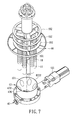
- FIG. 7 is a partly exploded perspective view of an assembly of the inlet conduit, the motor, the horizontal conveying shaft, perforated hollow pillars and a stirrer of the preferred embodiment;
- FIG. 8 is a partly exploded side view of an assembly of the preheating funnel, a feed hopper, a material outlet conduit, and a weight-controlling valve mechanism of the preferred embodiment.
- FIG. 9 is a fragmentary perspective view of the assembly of the weight-controlling valve mechanism and the material outlet conduit of the preferred embodiment.
- FIGS. 1 to 4 illustrate the preferred embodiment of an aluminum-based material melting apparatus according to the present invention.
- the aluminum-based material melting apparatus includes a furnace 3 , a plurality of heating elements 31 , a temperature sensor 32 , a melt level sensor 33 , a melt-discharging conduit 38 , a driving mechanism, a transmission mechanism, a scoop member 52 , a preheating funnel 41 , an inlet conduit 43 , a horizontal conveying shaft 42 , a discharging tube 422 , a vertical screw feeder shaft 461 , a plurality of perforated hollow pillars 44 , a stirrer 46 , a feed hopper 45 , a material outlet conduit 451 , and a weight-controlling valve mechanism 40 .
- the feed hopper 45 stores an aluminum-based raw material (not shown) therein.
- the aluminum-based raw material is in the form of aluminum or aluminum alloy particles.
- the driving mechanism includes first and second driving motors 511 , 512 .
- the transmission mechanism includes first and second shafts 516 , 517 , a worm wheel 514 , a worm 515 , a linking shaft 523 that defines a first axis (X), a rack 513 and a pinion 519 .
- the furnace 3 includes a main body 30 and a furnace cover 302 which covers a top opening of the main body 30 and which cooperates with the main body 30 to define a furnace space 305 for accommodating an aluminum-based melt 90 therein.
- the melt-discharging conduit 38 has an inner portion 381 disposed in the furnace space 305 , and an outer portion 383 disposed outwardly of the furnace space 305 and cooperating with the inner portion 381 to define a melt passage 384 for passage of the aluminum-based melt 90 therethrough.
- the inner portion 381 is disposed above a surface of the aluminum-based melt 90 in the furnace space 305 .
- the heating elements 31 and the temperature sensor 32 are mounted on the furnace cover 302 , extend into the furnace space 305 , and each is partially immersed in the aluminum-based melt 90 .
- the heating elements 31 are electrically powered to generate heat to melt the aluminum-based raw material received in the furnace space 305 under a melting temperature of above 680° C.
- a temperature controller (not shown) is connected to the temperature sensor 32 and the heating elements 31 to control power on and off states of the heating elements 31 based on a temperature signal generated by the temperature sensor 32 .
- the melt level sensor 33 is mounted on the furnace 3 for detecting the level of the aluminum-based melt 90 .
- the driving mechanism and the transmission mechanism are mounted on the furnace cover 302 of the furnace 3 .
- the scoop member 52 is suspended in the furnace space 305 , and is driven by the driving mechanism through the transmission mechanism so as to be movable upwardly and downwardly in the furnace space 305 between upper and lower positions (see FIGS. 5 and 2 ) and so as to be rotatable relative to the furnace 3 about the first axis (X) between scooping and pouring positions (see FIGS. 2 and 5 ) so that the scoop member 52 can scoop the aluminum-based melt 90 when disposed at the lower position and the scooping position (see FIG. 2 ) and that the scoop member 52 can pour the aluminum-based melt 90 into the inner portion 381 of the melt-discharging conduit 38 when disposed at the upper position and the pouring position (see FIG. 5 ), thereby permitting discharging of the aluminum-based melt 90 from the furnace space 305 into a casting mold 6 .
- first and second shafts 516 , 517 are mounted movably on the furnace 3 , extend through the furnace cover 302 , and are coaxially disposed with respect to a second axis (Y) which is perpendicular to the first axis (X).
- the second shaft 517 is disposed in the first shaft 516 , and is coupled rotatably to the first shaft 516 through a bearing set (not shown).
- the first driving motor 511 has an output shaft 518 .
- the rack 513 is secured to the first shaft 516 .
- the pinion 519 is coaxially and securely sleeved on the output shaft 518 , and meshes with the rack 513 for driving co-movement of the first and second shafts 516 , 517 along the second axis (Y) when the first driving motor 511 is actuated.
- the second driving motor 512 drives rotation of the second shaft 517 relative to the first shaft 516 about the second axis (Y).
- the worm 515 is secured to the second shaft 517 .
- the linking shaft 523 is secured to a bottom of the scoop member 52 .
- the worm wheel 514 is secured to the linking shaft 523 , and meshes with the worm 515 for driving rotation of the scoop member 52 relative to the first shaft 516 about the first axis (X) when the second driving motor 512 is actuated.
- a motor controller (not shown) is connected to the second driving motor 512 for controlling the rotational angle of the scoop member 52 so that the amount of the aluminum-based melt 90 scooped into the scoop member 52 can be controlled.
- the preheating funnel 41 is disposed above and is mounted on the furnace cover 302 of the furnace 3 , defines a funnel space 410 for receiving the aluminum-based raw material from the feed hopper 45 , and has an inlet port 412 for passage of the aluminum-based raw material, delivered from the feed hopper 45 , therethrough and into the funnel space 410 .
- the vertical screw feeder shaft 461 is disposed rotatably in the funnel space 410 for driving downward movement of the aluminum-based raw material in the funnel space 410 .
- the inlet conduit 43 interconnects the preheating funnel 41 and the furnace 3 , and has an annular upper portion 432 and an annular lower portion 433 that extends downwardly from the upper portion 432 through a top inlet hole 303 in the furnace cover 302 .
- the upper portion 432 of the inlet conduit 43 has an inner wall surface that defines a central space 430 in fluid communication with the furnace space 305 and the funnel space 410 for passage of the aluminum-based raw material, delivered from the funnel space 410 , therethrough and into the furnace space 305 .
- the horizontal conveying shaft 42 extends transversely through the upper portion 432 of the inlet conduit 43 , is driven by a third driving motor 421 to rotate about its axis relative to the inlet conduit 43 , and is formed with a plurality of radially extending blades 423 that protrude therefrom into the central space 430 for conveying the aluminum-based raw material from the central space 430 into the furnace space 305 when the horizontal conveying shaft 42 rotates about its axis.
- the upper portion 432 of the inlet conduit 43 is connected to the preheating funnel 41 , has a truncated conical top surface 4322 (see FIG. 7 ), and is formed with a plurality of axial holes 431 that extend axially along the length of the upper portion 432 through the top surface 4322 , and that are angularly displaced from one another to surround the central space 430 .
- the perforated hollow pillars 44 are disposed in the funnel space 410 , are angularly displaced from one another to surround the vertical screw feeder shaft 461 , extend respectively in a vertical direction into the axial holes 431 in the upper portion 432 of the inlet conduit 43 , and each is formed with a plurality of through-holes 441 in fluid communication with the funnel space 410 , thereby permitting fluid flow of a hot gas, arisen from the furnace space 305 and through the axial holes 431 , therethrough and into the funnel space 410 to preheat the aluminum-based raw material in the funnel space 410 and to remove moisture from the aluminum-based raw material.
- the aluminum-based raw material in the funnel space 410 can be preheated to a temperature ranging from 450° C. to 550° C. by the fluid flow of the hot gas and radiation heat radiated from the aluminum-based melt 90 and the heating elements 31 .
- the discharging tube 422 extends downwardly along the axis of the vertical screw feeder shaft 461 from a bottom end 4321 of the upper portion 432 through the lower portion 433 of the inlet conduit 43 and into the furnace space 305 , and is in spatial communication with the central space 430 for passage of the aluminum-based raw material therethrough and into the furnace space 305 .
- the stirrer 46 is disposed in the funnel space 410 above the vertical screw feeder shaft 461 , and has a plurality of annular blades 462 (see FIG. 7 ) for stirring the aluminum-based raw material in the funnel space 410 for facilitating conveying of the aluminum-based raw material from the funnel space 410 to the furnace space 305 .
- the material outlet conduit 451 interconnects the feed hopper 45 and the inlet port 412 , and has an upper segment 4512 and a lower segment 4513 .
- the upper segment 4512 defines a central axis (L).
- the lower segment 4513 extends downwardly from the upper segment 4512 in an inclined direction relative to the central axis (L), and defines a bottom end opening 4515 .
- the weight-controlling valve mechanism 40 utilizes the lever principle to control covering and uncovering of the bottom end opening 4515 in the lower segment 4513 of the material outlet conduit 451 , and includes a valve plate 453 having a bottom surface 4531 , a first linkage 458 connected to the bottom surface 4531 of the valve plate 453 through an angle plate 450 , a driving shaft 457 connected to and transverse to the first linkage 458 and pivoted to the inlet port 412 , a second linkage 455 connected and transverse to an end of the driving shaft 457 , and a weight block 456 connected to the second linkage 455 for providing a downward force acting on the second linkage 455 for driving rotation of the driving shaft 457 together with the first linkage 458 and the valve plate 453 about an axis of the driving shaft 457 in a downward rotational direction so as to rotate the valve plate 453 to a closed position (see FIGS.
- the valve plate 453 is rotatable together with the first linkage 458 , the driving shaft 457 , the second linkage 455 and the weight block 456 about the axis of the driving shaft 457 in an upward rotational direction opposite to the downward rotational direction when the weight of the aluminum-based raw material loaded on a top surface of the valve plate 453 overcomes the weight of the weight block 456 , thereby uncovering the bottom end opening 4515 (not shown) and permitting passage of the aluminum-based raw material therethrough and into the funnel space 305 .
- the amount of the aluminum-based melt 90 received in the scoop member 52 can be controlled.
- the purpose of energy saving can be achieved.
Landscapes
- Engineering & Computer Science (AREA)
- Mechanical Engineering (AREA)
- General Engineering & Computer Science (AREA)
- Chemical & Material Sciences (AREA)
- Metallurgy (AREA)
- Materials Engineering (AREA)
- Manufacturing & Machinery (AREA)
- Organic Chemistry (AREA)
- Environmental & Geological Engineering (AREA)
- Vertical, Hearth, Or Arc Furnaces (AREA)
- Manufacture And Refinement Of Metals (AREA)
- Furnace Details (AREA)
- Waste-Gas Treatment And Other Accessory Devices For Furnaces (AREA)
- Crucibles And Fluidized-Bed Furnaces (AREA)
- Furnace Charging Or Discharging (AREA)
Abstract
Description
- This application claims priority of Taiwanese Application No. 101130646, filed on Aug. 23, 2012.
- 1. Field of the Invention
- This invention relates to an aluminum-based material melting apparatus, more particularly to an aluminum-based material melting apparatus including a scoop member that is movable upwardly and downwardly and that is rotatable in a furnace for scooping and pouring an aluminum-based melt.
- 2. Description of the Related Art
- U.S. Pat. No. 3,070,437 discloses a rotary furnace for melting aluminum in a molten salt on a continuous operation basis. The rotary furnace includes a furnace body and a plurality of scoops formed on an inner wall of the furnace body and rotatable together with the furnace body for scooping an aluminum melt in the furnace body. A collecting member extends into the furnace body for collecting the aluminum melt spilled from the scoops. A feed hopper is connected to the rotary furnace through a feed conduit that extends into the furnace body for delivering aluminum solids into the furnace body.
- An object of the present invention is to provide an aluminum-based material melting apparatus that is energy saving and that can directly deliver a controllable amount of an aluminum-based melt to a casting die.
- According to this invention, there is provided an aluminum-based material melting apparatus that comprises: a furnace defining a furnace space and adapted to accommodate an aluminum-based melt in the furnace space; a melt-discharging conduit having an inner portion disposed in the furnace space, and an outer portion disposed outwardly of the furnace space, the inner portion being adapted to be disposed above a surface of the aluminum-based melt in the furnace space; a driving mechanism mounted on the furnace; a transmission mechanism connected to the driving mechanism; and a scoop member suspended in the furnace space and driven by the driving mechanism through the transmission mechanism so as to be movable upwardly and downwardly in the furnace space between upper and lower positions and so as to be rotatable relative to the furnace about an axis between scooping and pouring positions so that the scoop member can scoop the aluminum-based melt when disposed at the lower position and the scooping position and that the scoop member can pour the aluminum-based melt into the inner portion of the melt-discharging conduit when disposed at the upper position and the pouring position.
- In drawings which illustrate an embodiment of the invention,
-
FIG. 1 is a perspective view of the preferred embodiment of an aluminum-based material melting apparatus according to the present invention; -
FIG. 2 is a sectional view of the preferred embodiment, illustrating a scoop member at a scooping position; -
FIG. 3 is a perspective view of a driving mechanism and an assembly of a rack and a pinion of the preferred embodiment; -
FIG. 4 is a perspective view of an assembly of first and second shafts, a worm, a worm wheel and the scoop member of the preferred embodiment; -
FIG. 5 is a sectional view illustrating another state where the scoop member is disposed at a pouring position; -
FIG. 6 is a fragmentary perspective view of an assembly of a preheating funnel, an inlet conduit, a motor, and a horizontal conveying shaft of the preferred embodiment; -
FIG. 7 is a partly exploded perspective view of an assembly of the inlet conduit, the motor, the horizontal conveying shaft, perforated hollow pillars and a stirrer of the preferred embodiment; -
FIG. 8 is a partly exploded side view of an assembly of the preheating funnel, a feed hopper, a material outlet conduit, and a weight-controlling valve mechanism of the preferred embodiment; and -
FIG. 9 is a fragmentary perspective view of the assembly of the weight-controlling valve mechanism and the material outlet conduit of the preferred embodiment. -
FIGS. 1 to 4 illustrate the preferred embodiment of an aluminum-based material melting apparatus according to the present invention. The aluminum-based material melting apparatus includes afurnace 3, a plurality ofheating elements 31, atemperature sensor 32, amelt level sensor 33, a melt-discharging conduit 38, a driving mechanism, a transmission mechanism, ascoop member 52, apreheating funnel 41, aninlet conduit 43, ahorizontal conveying shaft 42, adischarging tube 422, a verticalscrew feeder shaft 461, a plurality of perforatedhollow pillars 44, astirrer 46, afeed hopper 45, amaterial outlet conduit 451, and a weight-controllingvalve mechanism 40. The feed hopper 45 stores an aluminum-based raw material (not shown) therein. Preferably, the aluminum-based raw material is in the form of aluminum or aluminum alloy particles. The driving mechanism includes first andsecond driving motors second shafts worm wheel 514, aworm 515, a linkingshaft 523 that defines a first axis (X), arack 513 and apinion 519. - The
furnace 3 includes amain body 30 and afurnace cover 302 which covers a top opening of themain body 30 and which cooperates with themain body 30 to define afurnace space 305 for accommodating an aluminum-basedmelt 90 therein. The melt-dischargingconduit 38 has aninner portion 381 disposed in thefurnace space 305, and anouter portion 383 disposed outwardly of thefurnace space 305 and cooperating with theinner portion 381 to define amelt passage 384 for passage of the aluminum-basedmelt 90 therethrough. Theinner portion 381 is disposed above a surface of the aluminum-basedmelt 90 in thefurnace space 305. - The
heating elements 31 and thetemperature sensor 32 are mounted on thefurnace cover 302, extend into thefurnace space 305, and each is partially immersed in the aluminum-basedmelt 90. Theheating elements 31 are electrically powered to generate heat to melt the aluminum-based raw material received in thefurnace space 305 under a melting temperature of above 680° C. A temperature controller (not shown) is connected to thetemperature sensor 32 and theheating elements 31 to control power on and off states of theheating elements 31 based on a temperature signal generated by thetemperature sensor 32. Themelt level sensor 33 is mounted on thefurnace 3 for detecting the level of the aluminum-basedmelt 90. The driving mechanism and the transmission mechanism are mounted on thefurnace cover 302 of thefurnace 3. - The
scoop member 52 is suspended in thefurnace space 305, and is driven by the driving mechanism through the transmission mechanism so as to be movable upwardly and downwardly in thefurnace space 305 between upper and lower positions (seeFIGS. 5 and 2 ) and so as to be rotatable relative to thefurnace 3 about the first axis (X) between scooping and pouring positions (seeFIGS. 2 and 5 ) so that thescoop member 52 can scoop the aluminum-basedmelt 90 when disposed at the lower position and the scooping position (seeFIG. 2 ) and that thescoop member 52 can pour the aluminum-basedmelt 90 into theinner portion 381 of the melt-dischargingconduit 38 when disposed at the upper position and the pouring position (seeFIG. 5 ), thereby permitting discharging of the aluminum-basedmelt 90 from thefurnace space 305 into acasting mold 6. - In this embodiment, the first and
second shafts furnace 3, extend through thefurnace cover 302, and are coaxially disposed with respect to a second axis (Y) which is perpendicular to the first axis (X). Thesecond shaft 517 is disposed in thefirst shaft 516, and is coupled rotatably to thefirst shaft 516 through a bearing set (not shown). - The
first driving motor 511 has anoutput shaft 518. Therack 513 is secured to thefirst shaft 516. Thepinion 519 is coaxially and securely sleeved on theoutput shaft 518, and meshes with therack 513 for driving co-movement of the first andsecond shafts first driving motor 511 is actuated. Thesecond driving motor 512 drives rotation of thesecond shaft 517 relative to thefirst shaft 516 about the second axis (Y). Theworm 515 is secured to thesecond shaft 517. The linkingshaft 523 is secured to a bottom of thescoop member 52. Theworm wheel 514 is secured to the linkingshaft 523, and meshes with theworm 515 for driving rotation of thescoop member 52 relative to thefirst shaft 516 about the first axis (X) when thesecond driving motor 512 is actuated. A motor controller (not shown) is connected to thesecond driving motor 512 for controlling the rotational angle of thescoop member 52 so that the amount of the aluminum-basedmelt 90 scooped into thescoop member 52 can be controlled. - The preheating
funnel 41 is disposed above and is mounted on thefurnace cover 302 of thefurnace 3, defines afunnel space 410 for receiving the aluminum-based raw material from thefeed hopper 45, and has aninlet port 412 for passage of the aluminum-based raw material, delivered from thefeed hopper 45, therethrough and into thefunnel space 410. The verticalscrew feeder shaft 461 is disposed rotatably in thefunnel space 410 for driving downward movement of the aluminum-based raw material in thefunnel space 410. - The
inlet conduit 43 interconnects the preheatingfunnel 41 and thefurnace 3, and has an annularupper portion 432 and an annularlower portion 433 that extends downwardly from theupper portion 432 through atop inlet hole 303 in thefurnace cover 302. Theupper portion 432 of theinlet conduit 43 has an inner wall surface that defines acentral space 430 in fluid communication with thefurnace space 305 and thefunnel space 410 for passage of the aluminum-based raw material, delivered from thefunnel space 410, therethrough and into thefurnace space 305. - Referring to
FIGS. 6 and 7 , in combination withFIG. 2 , thehorizontal conveying shaft 42 extends transversely through theupper portion 432 of theinlet conduit 43, is driven by a third drivingmotor 421 to rotate about its axis relative to theinlet conduit 43, and is formed with a plurality of radially extendingblades 423 that protrude therefrom into thecentral space 430 for conveying the aluminum-based raw material from thecentral space 430 into thefurnace space 305 when thehorizontal conveying shaft 42 rotates about its axis. - The
upper portion 432 of theinlet conduit 43 is connected to the preheatingfunnel 41, has a truncated conical top surface 4322 (seeFIG. 7 ), and is formed with a plurality ofaxial holes 431 that extend axially along the length of theupper portion 432 through thetop surface 4322, and that are angularly displaced from one another to surround thecentral space 430. The perforatedhollow pillars 44 are disposed in thefunnel space 410, are angularly displaced from one another to surround the verticalscrew feeder shaft 461, extend respectively in a vertical direction into theaxial holes 431 in theupper portion 432 of theinlet conduit 43, and each is formed with a plurality of through-holes 441 in fluid communication with thefunnel space 410, thereby permitting fluid flow of a hot gas, arisen from thefurnace space 305 and through theaxial holes 431, therethrough and into thefunnel space 410 to preheat the aluminum-based raw material in thefunnel space 410 and to remove moisture from the aluminum-based raw material. The aluminum-based raw material in thefunnel space 410 can be preheated to a temperature ranging from 450° C. to 550° C. by the fluid flow of the hot gas and radiation heat radiated from the aluminum-basedmelt 90 and theheating elements 31. - The
discharging tube 422 extends downwardly along the axis of the verticalscrew feeder shaft 461 from abottom end 4321 of theupper portion 432 through thelower portion 433 of theinlet conduit 43 and into thefurnace space 305, and is in spatial communication with thecentral space 430 for passage of the aluminum-based raw material therethrough and into thefurnace space 305. - The
stirrer 46 is disposed in thefunnel space 410 above the verticalscrew feeder shaft 461, and has a plurality of annular blades 462 (seeFIG. 7 ) for stirring the aluminum-based raw material in thefunnel space 410 for facilitating conveying of the aluminum-based raw material from thefunnel space 410 to thefurnace space 305. - Referring to
FIGS. 8 and 9 , in combination withFIG. 2 , the material outlet conduit 451 interconnects thefeed hopper 45 and theinlet port 412, and has anupper segment 4512 and alower segment 4513. Theupper segment 4512 defines a central axis (L). Thelower segment 4513 extends downwardly from theupper segment 4512 in an inclined direction relative to the central axis (L), and defines a bottom end opening 4515. - The weight-controlling
valve mechanism 40 utilizes the lever principle to control covering and uncovering of thebottom end opening 4515 in thelower segment 4513 of thematerial outlet conduit 451, and includes avalve plate 453 having abottom surface 4531, afirst linkage 458 connected to thebottom surface 4531 of thevalve plate 453 through anangle plate 450, a drivingshaft 457 connected to and transverse to thefirst linkage 458 and pivoted to theinlet port 412, asecond linkage 455 connected and transverse to an end of the drivingshaft 457, and aweight block 456 connected to thesecond linkage 455 for providing a downward force acting on thesecond linkage 455 for driving rotation of the drivingshaft 457 together with thefirst linkage 458 and thevalve plate 453 about an axis of the drivingshaft 457 in a downward rotational direction so as to rotate thevalve plate 453 to a closed position (seeFIGS. 8 and 9 ) to cover thebottom end opening 4515. Thevalve plate 453 is rotatable together with thefirst linkage 458, the drivingshaft 457, thesecond linkage 455 and theweight block 456 about the axis of the drivingshaft 457 in an upward rotational direction opposite to the downward rotational direction when the weight of the aluminum-based raw material loaded on a top surface of thevalve plate 453 overcomes the weight of theweight block 456, thereby uncovering the bottom end opening 4515 (not shown) and permitting passage of the aluminum-based raw material therethrough and into thefunnel space 305. - With the inclusion of the
scoop member 52, the driving mechanism and the transmission mechanism in the aluminum-based material melting apparatus of this invention, the amount of the aluminum-basedmelt 90 received in thescoop member 52, which is to be discharged to the castingmold 6, can be controlled. Moreover, with the inclusion of theaxial holes 431 in theinlet conduit 43 and the perforatedhollow pillars 44 in the preheatingfunnel 41 in the aluminum-based material melting apparatus of this invention, the purpose of energy saving can be achieved. - While the present invention has been described in connection with what is considered the most practical and preferred embodiment, it is understood that this invention is not limited to the disclosed embodiment but is intended to furnace cover various arrangements included within the spirit and scope of the broadest interpretation and equivalent arrangements.
Claims (5)
Applications Claiming Priority (3)
| Application Number | Priority Date | Filing Date | Title |
|---|---|---|---|
| TW101130646A TW201408398A (en) | 2012-08-23 | 2012-08-23 | Method and device for supplying aluminum alloy melt |
| TW101130646A | 2012-08-23 | ||
| TW101130646 | 2012-08-23 |
Publications (2)
| Publication Number | Publication Date |
|---|---|
| US20140054832A1 true US20140054832A1 (en) | 2014-02-27 |
| US9188390B2 US9188390B2 (en) | 2015-11-17 |
Family
ID=47678635
Family Applications (1)
| Application Number | Title | Priority Date | Filing Date |
|---|---|---|---|
| US13/752,725 Expired - Fee Related US9188390B2 (en) | 2012-08-23 | 2013-01-29 | Aluminum-based material melting apparatus |
Country Status (6)
| Country | Link |
|---|---|
| US (1) | US9188390B2 (en) |
| EP (1) | EP2700892A3 (en) |
| JP (1) | JP5583231B2 (en) |
| KR (1) | KR101399466B1 (en) |
| CN (2) | CN103624243B (en) |
| TW (1) | TW201408398A (en) |
Cited By (8)
| Publication number | Priority date | Publication date | Assignee | Title |
|---|---|---|---|---|
| US10119763B2 (en) | 2015-05-25 | 2018-11-06 | Chai-Long Yu | Apparatus for feeding raw material bars to a melting furnace |
| CN109059569A (en) * | 2018-09-21 | 2018-12-21 | 广东兴发铝业(江西)有限公司 | A kind of energy-saving type heat energy circulating device for aluminum profile processing |
| USD926241S1 (en) * | 2020-08-24 | 2021-07-27 | Yewei LI | Metal melting furnace |
| CN114523087A (en) * | 2022-02-25 | 2022-05-24 | 吉林大学 | Aluminum alloy melt quantitative pouring device for extrusion casting |
| CN117928229A (en) * | 2024-03-21 | 2024-04-26 | 徐州冠华机械制造有限公司 | Smelting furnace loading attachment |
| CN117989854A (en) * | 2024-02-21 | 2024-05-07 | 沂水晟佰钛业科技有限公司 | A smelting device for smelting titanium alloy |
| KR102737436B1 (en) * | 2024-01-11 | 2024-12-04 | 주식회사 르본인터내셔널 | An Ag-Cu wire Manufacturing Apparatus inclding variable raw material inlet for Electric contact |
| CN119353916A (en) * | 2024-12-27 | 2025-01-24 | 洛阳金涛华印新材料有限公司 | An integrated device for opening the cover and scooping slag from an aluminum smelting furnace and a method for using the same |
Families Citing this family (14)
| Publication number | Priority date | Publication date | Assignee | Title |
|---|---|---|---|---|
| CN103983105A (en) * | 2014-05-29 | 2014-08-13 | 芜湖长启炉业有限公司 | Direct heating aluminum base material melting furnace |
| CN104571150B (en) * | 2014-11-19 | 2017-03-29 | 田志恒 | Fused ceramic fiber flow control system |
| TWI614072B (en) * | 2015-02-06 | 2018-02-11 | 楊文銓 | Smelting apparatus and method for smelting metal materials |
| CN105369294B (en) * | 2015-09-01 | 2018-05-15 | 包头市玺骏稀土有限责任公司 | The apparatus and method that a kind of rare earth electrolysis cell goes out metal |
| CN105798275A (en) * | 2016-03-16 | 2016-07-27 | 高诗白 | Electromagnetic induction heating metal liquid forming equipment and process |
| CN108639589A (en) * | 2018-06-15 | 2018-10-12 | 衡东县中湖包装有限公司 | A kind of hot melt hopper |
| CN109604561A (en) * | 2018-11-13 | 2019-04-12 | 苏州卡利肯新光讯科技有限公司 | A kind of feedway of metallic solution |
| US11027333B2 (en) * | 2019-03-22 | 2021-06-08 | Sukhjinder Kullar | Liquid-resistant direct-drive robotic ladler |
| CN110238355B (en) * | 2019-06-06 | 2022-01-21 | 东风本田汽车有限公司 | Weighing, temperature measuring and hydrogen removing same-station integrated equipment and weighing, temperature measuring and hydrogen removing method thereof |
| CN111673067A (en) * | 2020-06-11 | 2020-09-18 | 张亮 | Novel intelligent linkage type soup feeding machine for die casting machine |
| CN111854445B (en) * | 2020-07-20 | 2024-09-24 | 沁阳市中冉耐火材料有限公司 | A feeding device for a vertical bauxite calcining kiln |
| CN112795804B (en) * | 2020-12-27 | 2021-11-09 | 上海交通大学安徽(淮北)陶铝新材料研究院 | Method for controlling in-situ authigenic aluminum-based composite material by melt with continuous treatment |
| CN114226706B (en) * | 2021-12-30 | 2023-03-28 | 万丰镁瑞丁新材料科技有限公司 | Automatic slagging-off device of die-casting |
| CN120593509B (en) * | 2025-08-07 | 2025-10-17 | 陕西九木晟焰新材料有限公司 | A magnesium alloy vacuum melting furnace |
Citations (6)
| Publication number | Priority date | Publication date | Assignee | Title |
|---|---|---|---|---|
| US3398782A (en) * | 1964-02-28 | 1968-08-27 | Lauterjung Gustav | Automatic ladling device |
| US4741514A (en) * | 1984-02-23 | 1988-05-03 | Gerhard Bleickert | High temperature and/or melting furnace for non-ferrous metals with dosing device |
| US4891204A (en) * | 1984-07-21 | 1990-01-02 | Scm Chemical Limited | Purification of aluminum chloride |
| US5131452A (en) * | 1989-08-23 | 1992-07-21 | Alcan Deutschland Gmbh | Method and apparatus for the dosed removal molten metal out of a melt vessel |
| US5341394A (en) * | 1992-08-31 | 1994-08-23 | Nicem S.R.L. | Furnace for melting materials with low melting point with improved casting duct |
| CN101073828A (en) * | 2007-06-22 | 2007-11-21 | 石家庄镁淇科技发展有限公司 | Apparatus for pouring magnesium-alloy quantitatively |
Family Cites Families (26)
| Publication number | Priority date | Publication date | Assignee | Title |
|---|---|---|---|---|
| US3070437A (en) | 1961-03-14 | 1962-12-25 | Gen Motors Corp | Method and apparatus for melting aluminum in a salt bath rotary furnace |
| GB1375520A (en) * | 1973-08-31 | 1974-11-27 | ||
| JPS5639160A (en) * | 1979-09-04 | 1981-04-14 | Aisin Seiki Co Ltd | Automatic molten metal feeder |
| JPS5914302B2 (en) * | 1980-09-02 | 1984-04-04 | 東芝機械株式会社 | automatic water heater |
| JPS61205654A (en) | 1985-03-09 | 1986-09-11 | 電気化学工業株式会社 | Superhigh strength cement concrete composition |
| JPS61205654U (en) * | 1985-06-17 | 1986-12-25 | ||
| JPH0623655U (en) * | 1992-09-01 | 1994-03-29 | 本田技研工業株式会社 | Automatic water heater |
| JPH07190629A (en) * | 1993-04-15 | 1995-07-28 | Ishikawajima Harima Heavy Ind Co Ltd | Scrap material preheating charging device |
| JPH08238559A (en) * | 1995-03-02 | 1996-09-17 | Kiyoshi Fujino | Ladle for supplying molten metal into casting machine |
| JPH09216042A (en) * | 1996-02-06 | 1997-08-19 | Ube Ind Ltd | Hot water supply method of closed hot water supply device |
| TW344789B (en) * | 1996-03-07 | 1998-11-11 | Daido Steel Co Ltd | Preheating device for melting materials and melting furnace having preheating device |
| TW460584B (en) | 1996-07-15 | 2001-10-21 | Nippon Crucible Co | Continuous melting apparatus for law-melting point metal, improved crucible for such apparatus, and melting method using such apparatus |
| US6024912A (en) * | 1997-11-27 | 2000-02-15 | Empco (Canada) Ltd. | Apparatus and process system for preheating of steel scrap for melting metallurgical furnaces with concurrent flow of scrap and heating gases |
| DE19807590A1 (en) * | 1998-02-23 | 1999-08-26 | Arcmet Tech Gmbh | Charge preheater for melting furnaces |
| JP3796617B2 (en) * | 1998-10-23 | 2006-07-12 | 日本坩堝株式会社 | Melting and holding furnace such as aluminum ingot |
| JP2000317612A (en) * | 1999-05-14 | 2000-11-21 | Toda Seiki Kk | Ladle inclining device for die casting |
| JP2001234204A (en) * | 2000-02-17 | 2001-08-28 | Kawasaki Steel Corp | Heating equipment for metal powder |
| US6447288B1 (en) * | 2000-06-01 | 2002-09-10 | Energy Research Company | Heat treating apparatus |
| JP3074007U (en) * | 2000-06-13 | 2000-12-19 | 利坤 林 | Furnace structure of die casting machine |
| CN1251827C (en) * | 2000-06-22 | 2006-04-19 | 株式会社丰荣商会 | molten metal supply container |
| US6893607B2 (en) * | 2001-09-07 | 2005-05-17 | Premelt Systems, Inc. | Elevated discharge gas lift bubble pump and furnace for use therewith |
| AT411363B (en) * | 2002-02-21 | 2003-12-29 | Tribovent Verfahrensentwicklg | DEVICE FOR MELTING DUST |
| CN201069308Y (en) * | 2007-06-08 | 2008-06-04 | 正英工业燃烧设备(上海)有限公司 | A heat accumulation aluminum alloy fusion keeping furnace |
| TWM323587U (en) * | 2007-07-02 | 2007-12-11 | Suncue Co Ltd | Material feeding device |
| KR101121148B1 (en) * | 2009-12-24 | 2012-03-19 | 권동철 | Device for casting ladle |
| CN201672799U (en) | 2010-05-12 | 2010-12-15 | 佛山市中科炉业有限公司 | Environment-friendly high-efficient aluminum metal melting holding furnace with low burning loss |
-
2012
- 2012-08-23 TW TW101130646A patent/TW201408398A/en not_active IP Right Cessation
- 2012-11-07 CN CN201210442543.XA patent/CN103624243B/en not_active Expired - Fee Related
- 2012-11-07 CN CN2012205852362U patent/CN202894300U/en not_active Expired - Fee Related
-
2013
- 2013-01-29 JP JP2013014221A patent/JP5583231B2/en not_active Expired - Fee Related
- 2013-01-29 US US13/752,725 patent/US9188390B2/en not_active Expired - Fee Related
- 2013-02-11 EP EP13154832.3A patent/EP2700892A3/en not_active Withdrawn
- 2013-03-14 KR KR1020130026993A patent/KR101399466B1/en not_active Expired - Fee Related
Patent Citations (6)
| Publication number | Priority date | Publication date | Assignee | Title |
|---|---|---|---|---|
| US3398782A (en) * | 1964-02-28 | 1968-08-27 | Lauterjung Gustav | Automatic ladling device |
| US4741514A (en) * | 1984-02-23 | 1988-05-03 | Gerhard Bleickert | High temperature and/or melting furnace for non-ferrous metals with dosing device |
| US4891204A (en) * | 1984-07-21 | 1990-01-02 | Scm Chemical Limited | Purification of aluminum chloride |
| US5131452A (en) * | 1989-08-23 | 1992-07-21 | Alcan Deutschland Gmbh | Method and apparatus for the dosed removal molten metal out of a melt vessel |
| US5341394A (en) * | 1992-08-31 | 1994-08-23 | Nicem S.R.L. | Furnace for melting materials with low melting point with improved casting duct |
| CN101073828A (en) * | 2007-06-22 | 2007-11-21 | 石家庄镁淇科技发展有限公司 | Apparatus for pouring magnesium-alloy quantitatively |
Cited By (8)
| Publication number | Priority date | Publication date | Assignee | Title |
|---|---|---|---|---|
| US10119763B2 (en) | 2015-05-25 | 2018-11-06 | Chai-Long Yu | Apparatus for feeding raw material bars to a melting furnace |
| CN109059569A (en) * | 2018-09-21 | 2018-12-21 | 广东兴发铝业(江西)有限公司 | A kind of energy-saving type heat energy circulating device for aluminum profile processing |
| USD926241S1 (en) * | 2020-08-24 | 2021-07-27 | Yewei LI | Metal melting furnace |
| CN114523087A (en) * | 2022-02-25 | 2022-05-24 | 吉林大学 | Aluminum alloy melt quantitative pouring device for extrusion casting |
| KR102737436B1 (en) * | 2024-01-11 | 2024-12-04 | 주식회사 르본인터내셔널 | An Ag-Cu wire Manufacturing Apparatus inclding variable raw material inlet for Electric contact |
| CN117989854A (en) * | 2024-02-21 | 2024-05-07 | 沂水晟佰钛业科技有限公司 | A smelting device for smelting titanium alloy |
| CN117928229A (en) * | 2024-03-21 | 2024-04-26 | 徐州冠华机械制造有限公司 | Smelting furnace loading attachment |
| CN119353916A (en) * | 2024-12-27 | 2025-01-24 | 洛阳金涛华印新材料有限公司 | An integrated device for opening the cover and scooping slag from an aluminum smelting furnace and a method for using the same |
Also Published As
| Publication number | Publication date |
|---|---|
| EP2700892A2 (en) | 2014-02-26 |
| JP5583231B2 (en) | 2014-09-03 |
| TW201408398A (en) | 2014-03-01 |
| TWI473677B (en) | 2015-02-21 |
| JP2014039956A (en) | 2014-03-06 |
| KR20140026237A (en) | 2014-03-05 |
| EP2700892A3 (en) | 2017-04-26 |
| KR101399466B1 (en) | 2014-06-27 |
| US9188390B2 (en) | 2015-11-17 |
| CN103624243A (en) | 2014-03-12 |
| CN202894300U (en) | 2013-04-24 |
| CN103624243B (en) | 2015-09-23 |
Similar Documents
| Publication | Publication Date | Title |
|---|---|---|
| US9188390B2 (en) | Aluminum-based material melting apparatus | |
| EP1846147B1 (en) | Kneading and granulating machine | |
| CN107262002A (en) | A kind of reactor for being used to have colloid product | |
| CN106492669A (en) | A kind of coating material production agitator tank | |
| CN109440000A (en) | Amorphous alloy smelting furnace molten iron guiding device | |
| JPH08155950A (en) | Mixing and defoaming apparatus | |
| CN109093848A (en) | A kind of high-effective concrete blender | |
| CN111070459A (en) | Automatic stirring equipment for PVC pipe raw materials | |
| CN209615972U (en) | It is poured blender | |
| CN207456167U (en) | A kind of automatic feeding device | |
| CN214842503U (en) | Distributing device for kiln | |
| JP4571659B2 (en) | Garbage fermentation processing equipment | |
| CN108854760A (en) | A kind of paint production dispersion mixing device | |
| CN204278234U (en) | mortar mixer | |
| CN210025954U (en) | Automatic feeding device | |
| CN203678290U (en) | Agitator | |
| CN208326751U (en) | A kind of sulphur feed device | |
| CN208218931U (en) | A kind of aluminum ingot melting device | |
| CN216578677U (en) | A plastic particle melting device | |
| CN213913674U (en) | A change wax device for low molecular weight polyethylene production | |
| CN214398966U (en) | Single-arm type rotatable feeding device | |
| CN100412214C (en) | Tin dross processor | |
| CN116659231A (en) | A sponge cadmium smelting and purification device and its application method | |
| CN223879807U (en) | Feed bin for electroslag furnace slag adder | |
| JP3182618U (en) | Horizontal dry crusher |
Legal Events
| Date | Code | Title | Description |
|---|---|---|---|
| STCF | Information on status: patent grant |
Free format text: PATENTED CASE |
|
| MAFP | Maintenance fee payment |
Free format text: PAYMENT OF MAINTENANCE FEE, 4TH YR, SMALL ENTITY (ORIGINAL EVENT CODE: M2551); ENTITY STATUS OF PATENT OWNER: SMALL ENTITY Year of fee payment: 4 |
|
| FEPP | Fee payment procedure |
Free format text: MAINTENANCE FEE REMINDER MAILED (ORIGINAL EVENT CODE: REM.); ENTITY STATUS OF PATENT OWNER: SMALL ENTITY |
|
| LAPS | Lapse for failure to pay maintenance fees |
Free format text: PATENT EXPIRED FOR FAILURE TO PAY MAINTENANCE FEES (ORIGINAL EVENT CODE: EXP.); ENTITY STATUS OF PATENT OWNER: SMALL ENTITY |
|
| STCH | Information on status: patent discontinuation |
Free format text: PATENT EXPIRED DUE TO NONPAYMENT OF MAINTENANCE FEES UNDER 37 CFR 1.362 |
|
| FP | Lapsed due to failure to pay maintenance fee |
Effective date: 20231117 |