US20130039730A1 - Robot - Google Patents
Robot Download PDFInfo
- Publication number
- US20130039730A1 US20130039730A1 US13/558,348 US201213558348A US2013039730A1 US 20130039730 A1 US20130039730 A1 US 20130039730A1 US 201213558348 A US201213558348 A US 201213558348A US 2013039730 A1 US2013039730 A1 US 2013039730A1
- Authority
- US
- United States
- Prior art keywords
- pressing member
- brake
- pressing
- horizontal arm
- arm unit
- Prior art date
- Legal status (The legal status is an assumption and is not a legal conclusion. Google has not performed a legal analysis and makes no representation as to the accuracy of the status listed.)
- Abandoned
Links
Images




Classifications
-
- B—PERFORMING OPERATIONS; TRANSPORTING
- B25—HAND TOOLS; PORTABLE POWER-DRIVEN TOOLS; MANIPULATORS
- B25J—MANIPULATORS; CHAMBERS PROVIDED WITH MANIPULATION DEVICES
- B25J19/00—Accessories fitted to manipulators, e.g. for monitoring, for viewing; Safety devices combined with or specially adapted for use in connection with manipulators
- B25J19/06—Safety devices
-
- B—PERFORMING OPERATIONS; TRANSPORTING
- B25—HAND TOOLS; PORTABLE POWER-DRIVEN TOOLS; MANIPULATORS
- B25J—MANIPULATORS; CHAMBERS PROVIDED WITH MANIPULATION DEVICES
- B25J19/00—Accessories fitted to manipulators, e.g. for monitoring, for viewing; Safety devices combined with or specially adapted for use in connection with manipulators
- B25J19/0004—Braking devices
-
- B—PERFORMING OPERATIONS; TRANSPORTING
- B25—HAND TOOLS; PORTABLE POWER-DRIVEN TOOLS; MANIPULATORS
- B25J—MANIPULATORS; CHAMBERS PROVIDED WITH MANIPULATION DEVICES
- B25J9/00—Program-controlled manipulators
- B25J9/02—Program-controlled manipulators characterised by movement of the arms, e.g. cartesian coordinate type
- B25J9/04—Program-controlled manipulators characterised by movement of the arms, e.g. cartesian coordinate type by rotating at least one arm, excluding the head movement itself, e.g. cylindrical coordinate type or polar coordinate type
- B25J9/041—Cylindrical coordinate type
- B25J9/042—Cylindrical coordinate type comprising an articulated arm
-
- B—PERFORMING OPERATIONS; TRANSPORTING
- B25—HAND TOOLS; PORTABLE POWER-DRIVEN TOOLS; MANIPULATORS
- B25J—MANIPULATORS; CHAMBERS PROVIDED WITH MANIPULATION DEVICES
- B25J9/00—Program-controlled manipulators
- B25J9/02—Program-controlled manipulators characterised by movement of the arms, e.g. cartesian coordinate type
- B25J9/04—Program-controlled manipulators characterised by movement of the arms, e.g. cartesian coordinate type by rotating at least one arm, excluding the head movement itself, e.g. cylindrical coordinate type or polar coordinate type
- B25J9/046—Revolute coordinate type
- B25J9/047—Revolute coordinate type the pivoting axis of the first arm being offset to the vertical axis
Definitions
- the present invention relates to a robot.
- Japanese Unexamined Patent Application Publication No. 2008-307618 discloses a robot including a motor.
- the motor includes a brake such as a non-excitation actuated electromagnetic brake.
- the brake is for the purpose of preventing, when power is off, displacement due to gravity of the components of the robot such as arms.
- a non-excitation actuated electromagnetic brake releases its braking force utilizing electromagnetic force when power is on, while when power is off, effects braking force utilizing mechanical action such as of springs.
- a robot includes a rotating electrical machine and a brake.
- the rotating electrical machine includes a shaft.
- the brake is configured to restrict rotation of the rotating electrical machine.
- the brake includes a brake plate, a plurality of pressing members, at least one biasing member, and an electromagnetic coil.
- the brake plate is configured to rotate integrally with the shaft of the rotating electrical machine.
- the plurality of pressing members are movable toward the brake plate and include a first pressing member and a second pressing member.
- the at least one biasing member is configured to bias the first pressing member and the second pressing member toward the brake plate using mutually different biasing forces.
- the electromagnetic coil is configured to, when current is on, electromagnetically attract the first pressing member and the second pressing member against the biasing forces of the at least one biasing member.
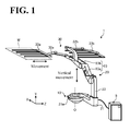
- FIG. 1 is a schematic perspective view of a robot according to embodiment 1;
- FIG. 2 is a schematic side view of the robot
- FIG. 3 is a schematic cross-sectional view of a servo motor
- FIG. 4 is an enlarged cross-sectional view of an internal brake
- FIG. 5 is a front view of a pressing member according to embodiment 1;
- FIG. 6 is an enlarged cross-sectional view of a third joint and other elements in the vicinity of the third joint;
- FIG. 7 is a block diagram illustrating an exemplary configuration of a control device
- FIG. 8 is a flowchart of an exemplary procedure for a diagnosis
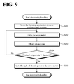
- FIG. 9 is a flowchart of an exemplary procedure for abnormality handling
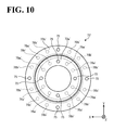
- FIG. 10 is a front view of a pressing member according to embodiment 2.
- FIG. 11 is a diagram illustrating an external brake according to embodiment 3.
- FIG. 12 is a schematic perspective view of a robot according to embodiment 4.
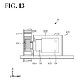
- FIG. 13 is a partially enlarged view of a robot according to embodiment 5.
- FIG. 1 is a schematic perspective view of the robot according to embodiment 1.
- the direction Y shown in FIG. 1 is assumed the upper direction.
- the robot according to this embodiment is a transfer robot with two hands, this should not be construed as limiting the number of hands.
- the transfer robot may have a single hand.
- the objects to be conveyed on the hands are thin plate workpieces such as LCD glass substrates and substrates for solar power generation. This, however, should not be construed as limiting the objects to be conveyed.
- the robot 1 includes a turning mechanism 10 , an elevating mechanism 20 , and a horizontal arm unit 30 .
- the turning mechanism 10 turns the elevating mechanism 20 and the horizontal arm unit 30 about a perpendicular pivot axis O.
- the elevating mechanism 20 includes a base 21 , a pillar 22 , and a leg unit 23 .
- the pillar 22 is upright on the base 21 .
- the leg unit 23 has a base end supported by the pillar 22 and a distal end supporting the horizontal arm unit 30 .
- the leg unit 23 includes a first leg 23 a and a second leg 23 b .
- the first leg 23 a has a base end rotatably supported at the pillar 22 , which is upright at one end of the base 21 .
- the second leg 23 b has a base end rotatably supported by the distal end of the first leg 23 a and a distal end rotatably supporting the horizontal arm unit 30 .
- the elevating mechanism 20 changes the posture of the leg unit 23 so as to move the horizontal arm unit 30 in vertical directions.
- the base 21 includes a stopper 21 a to contact the horizontal arm unit 30 when the elevating mechanism 20 moves down to its lowest position.
- the horizontal arm unit 30 includes hands 33 a and 33 b and arms 32 a and 32 b .
- the hands 33 a and 33 b carry workpieces W, which are objects to be conveyed.
- the arms 32 a and 32 b respectively support the hands 33 a and 33 b at the distal ends of the arms 32 a and 32 b .
- the horizontal arm unit 30 extends and retracts the arms 32 a and 32 b so as to move the hands 33 a and 33 b in predetermined directions. For example, when the robot 1 turns to the position shown in FIG. 1 , the arms 32 a and 32 b linearly move the hands 33 a and 33 b in the direction Z.
- the robot 1 When, for example, a workpiece W is stored in a stocker, not shown, the robot 1 according to embodiment 1 picks the workpiece W out of the stocker and conveys the workpiece W to a working area, not shown. While the following description is regarding conveyance by the hand 33 a , the same applies to conveyance by the hand 33 b .
- the robot 1 uses the elevating mechanism 20 to move up or down the horizontal arm unit 30 and to position the hand 33 a to a height slightly lower than the workpiece W to be taken out of the stocker.
- the robot 1 drives the arm 32 a to linearly move the hand 33 a in a horizontal direction and to insert the hand 33 a into the stocker storing the workpiece W.
- the elevating mechanism 20 then moves up the horizontal arm unit 30 , resulting in the workpiece W carried on the hand 33 a.
- the robot 1 retracts the arm 32 a to linearly withdraw the hand 33 a carrying the workpiece W from the stocker in a horizontal direction.
- the robot 1 then uses the turning mechanism 10 to turn the horizontal arm unit 30 and the elevating mechanism 20 and to orient the distal end of the hand 33 a toward the working area.
- the robot 1 again extends the arm 32 a to linearly move the hand 33 a in a horizontal direction and to make the hand 33 a reach the working area.
- the robot 1 then uses the elevating mechanism 20 to move down the horizontal arm unit 30 , thereby lowering the position of the hand 33 a and placing the workpiece W in the working area.
- the robot 1 conveys workpieces W by extending and retracting the arms 32 a and 32 b to move the hands 33 a and 33 b , by moving up and down the horizontal arm unit 30 using the elevating mechanism 20 , and by turning the horizontal arm unit 30 using the turning mechanism 10 .
- the robot 1 makes these movements on instruction from a control device 5 coupled to the robot 1 through a communication network.
- the control device 5 controls driving of the robot 1 .
- the robot 1 includes servo motors at the joints of the robot 1 .
- the control device 5 controls the driving of the servo motors.
- the robot 1 individually rotates the servo motors by certain degrees, thus driving the turning mechanism 10 , the elevating mechanism 20 , and the horizontal arm unit 30 .
- Examples of the communication network coupling the robot 1 and the control device 5 to one another include, but not limited to, common networks such as a wired Local Area Network (LAN) and a wireless LAN.
- LAN Local Area Network
- wireless LAN wireless LAN
- Each of the servo motors of the robot 1 includes a built-in brake to restrict rotation of the servo motor when driving power is off.
- the brake includes a brake plate, a pressing member, a biasing member, and an electromagnetic coil.
- the brake plate rotates integrally with the shaft of the servo motor.
- the pressing member is movable to the brake plate.
- the biasing member biases the pressing member to the brake plate.
- the electromagnetic coil electromagnetically attracts the pressing member against the biasing force of the biasing member when current is on.
- the pressing member of the brake presses the brake plate utilizing the biasing force of the biasing member, thus restricting rotation of the brake plate.
- the restriction of rotation of the brake plate leads to restriction of rotation of the shaft, which is configured to rotate integrally with the brake plate. This keeps the current posture of the robot 1 , and eliminates or minimizes displacement of the elevating mechanism 20 and the horizontal arm unit 30 .
- the braking force of the brake may degrade due to factors such as leakage of grease and deterioration over time of the brake shoe and the pressing member through friction.
- Conventional practice is to, for example, conduct periodic maintenance of the brake including replacement as necessary, in an attempt to prevent degradation of the braking force and to prevent displacement of the elevating mechanism 20 or other components caused by the degraded braking force. It is preferred, however, to more reliably prevent displacement of the elevating mechanism 20 or other components.
- the robot 1 according to embodiment 1 is of the type that supports the horizontal arm unit 30 on a single leg unit 23 , as shown in FIG. 1 .
- the elevating mechanism 20 or other components are more likely to be displaced due to the degraded braking force, compared with the type of robot including more than two leg units to support the horizontal arm unit 30 .
- the robot 1 according to embodiment 1 conveys LCD glass substrates and substrates for solar power generation. This kind of robots have been using increasing sizes of arms in accordance with the increasing sizes of substrates. This makes the arms heavier, and makes displacement of the arms more likely to occur.
- the robot 1 according to embodiment 1 includes a plurality of pressing members to press the brake plate. This ensures that even when any of the pressing members stops functioning due to factors such as deterioration over time and failure, the rest of the pressing members properly function to prevent displacement due to gravity of the elevating mechanism 20 or other components.
- the robot 1 according to embodiment 1 includes an additional brake outside the servo motor to restrict rotation of the servo motor, as well as the brake disposed inside the servo motor, in order to increase the braking force of the brake. This more reliably prevents displacement due to gravity of the elevating mechanism 20 or other components.
- the internal brake and the external brake are non-excitation actuated electromagnetic brakes
- FIG. 2 is a schematic side view of the robot 1 .
- the robot 1 includes a first joint 25 , a second joint 26 , and a third joint 27 .
- the first joint 25 couples the base end of the first leg 23 a to the distal end of the pillar 22 such that the base end of the first leg 23 a is rotatable about a rotation axis parallel to the direction Z.
- the second joint 26 couples the base end of the second leg 23 b to the distal end of the first leg 23 a such that the base end of the second leg 23 b is rotatable about a rotation axis parallel to the direction Z.
- the third joint 27 couples the horizontal arm unit 30 to the distal end of the second leg 23 b such that the horizontal arm unit 30 is rotatable about a rotation axis parallel to the direction Z.
- the first joint 25 includes a servo motor 41 a , a reducer 42 a , and an external brake 44 a .
- the second joint 26 includes a servo motor 41 b , a reducer 42 b , and an external brake 44 b .
- the third joint 27 includes a servo motor 41 c , a reducer 42 c , and an external brake 44 c .
- the servo motors 41 a to 41 c respectively include internal brakes 43 a to 43 c .
- the servo motors 41 a to 41 c are exemplary “rotating electrical machines”.
- the rotation of the servo motor 41 a is reduced by the reducer 42 a , and the reduced rotation is output to the first leg 23 a , causing the first leg 23 a to turn and change its posture relative to the pillar 22 .
- the internal brake 43 a and the external brake 44 a are activated to keep the current posture of the first leg 23 a relative to the pillar 22 .
- the rotation of the servo motor 41 b is reduced by the reducer 42 b , and the reduced rotation is output to the second leg 23 b , causing the second leg 23 b to turn and change its posture relative to the first leg 23 a .
- the internal brake 43 b and the external brake 44 b keep the current posture of the second leg 23 b relative to the first leg 23 a.
- the rotation of the servo motor 41 c is reduced by the reducer 42 c , and the reduced rotation is output to the horizontal arm unit 30 , causing the horizontal arm unit 30 to turn and change its posture relative to the second leg 23 b .
- the internal brake 43 c and the external brake 44 c keep the current posture of the horizontal arm unit 30 relative to the second leg 23 b.
- the pillar 22 , the leg unit 23 , and the horizontal arm unit 30 are coupled to each other with the leg unit 23 positioned between the horizontal arm unit 30 and the pillar 22 as viewed from the direction X. That is, the horizontal arm unit 30 , the second leg 23 b , the first leg 23 a , and the pillar 22 are disposed in the direction Z in this order. Each of these components is rotatably coupled to the next component.
- FIG. 3 is a schematic cross-sectional view of the servo motor 41 c .
- FIG. 4 is an enlarged cross-sectional view of the internal brake 43 c .
- the enlarged cross-sectional view shown in FIG. 4 is that of the internal brake 43 c in brake released state.
- the servo motor 41 c includes a motor main body 60 and the internal brake 43 c .
- the motor main body 60 includes a shaft 61 , a rotor 62 , and two bearings 63 .
- the shaft 61 extends in the direction Z.
- the rotor 62 is secured to the shaft 61 and rotates about the axis of the shaft 61 .
- the bearings 63 sandwich the rotor 62 in the direction Z and rotatably support the shaft 61 .
- the motor main body 60 includes a bracket 64 and a stator 65 .
- the bracket 64 covers the rotor 62 and the bearings 63 .
- the stator 65 is opposite the rotor 62 in the bracket 64 .
- a predetermined voltage is applied to the coil of the stator 65 , generating a rotational magnetic field on the stator 65 .
- the rotational magnetic field interacts with a magnetic field generated by the permanent magnets of the rotor 62 . This interaction causes the rotor 62 to rotate, which in turn causes the shaft 61 to rotate.
- the shaft 61 includes a spline 61 a extending in the direction Z at the distal end of the shaft 61 at its negative side in the direction Z (that is, the distal end of the shaft 61 at its internal brake 43 c side). That is, the distal end of the shaft 61 is in the form of an external gear on the outer circumferential surface.
- the spline 61 a engages with an internal gear on the inner circumferential surface of a brake plate 72 , described later. This causes the brake plate 72 to integrally rotate with the shaft 61 .
- the internal brake 43 c includes brake shoes 71 , the brake plate 72 , a pressing member 73 , bolts 74 , a guide 75 , and a field core 76 .
- the brake shoes 71 are made of rubber or other material of high friction resistance.
- the brake shoes 71 are disposed on the front surface and the rear surface of the brake plate 72 (that is, on the positive side and the negative side of the brake plate 72 in the direction Z). At the time of braking, the brake shoes 71 on the front surface contact the bracket 64 , while the brake shoes 71 on the rear surface contact the pressing member 73 .
- the brake plate 72 is ring shaped and has an internal gear on the inner circumferential surface.
- the inner circumferential surface of the brake plate 72 engages with the spline 61 a of the shaft 61 , causing the brake plate 72 to integrally rotate with the shaft 61 .
- the brake plate 72 is movable in the direction Z between the bracket 64 and the pressing member 73 .
- the pressing member 73 is disposed between the field core 76 and the brake plate 72 , and is supported by the guide 75 movably between the field core 76 and the brake plate 72 .
- the pressing member 73 is biased toward the brake plate 72 by helical compression springs 78 a and 78 b disposed on the field core 76 .
- the field core 76 is ring shaped and secured to the bracket 64 with the bolts 74 .
- the field core 76 contains a soft magnetic material.
- the field core 76 includes an electromagnetic coil 77 and the helical compression springs 78 a and 78 b.
- the electromagnetic coil 77 electromagnetically attracts the pressing member 73 when current is on, against the biasing forces of the helical compression springs 78 a and 78 b .
- the helical compression springs 78 a and 78 b bias the pressing member 73 toward the brake plate 72 .
- the helical compression springs 78 a and 78 b are examples of a “biasing member” and a “spring”.
- the pressing member 73 When driving power is off and the internal brake 43 c turns into non-excitation state, the pressing member 73 is pressed toward the bracket 64 by the biasing force of the helical compression springs 78 a and 78 b . This causes a friction force between the pressing member 73 and the opposing brake shoe 71 and a friction force between the bracket 64 and the opposing brake shoe 71 . The friction forces restrict the rotation of the brake plate 72 , which in turn restricts the rotation of the shaft 61 .
- the pressing member 73 which presses the brake plate 72 , includes two pressing members 73 a and 73 b .
- a configuration of the pressing member 73 will be described in detail by referring to FIG. 5 .
- FIG. 5 is a front view of the pressing member 73 according to embodiment 1.
- the pressing member 73 defines a single ring shape in the front view (as seen in the direction Z).
- the ring shape is cut in the radial direction into the two pressing members 73 a and 73 b . That is, the two pressing members 73 a and 73 b constitute the single ring shaped pressing member 73 .
- the two pressing members 73 a and 73 b have mutually different central angles. That is, the pressing member 73 is divided such that the pressing members 73 a and 73 b have mutually different central angles along the circumferential direction of the pressing member 73 . Specifically, the pressing member 73 a has a central angle of approximately 150 degrees, while the pressing member 73 b has a central angle of approximately 210 degrees.
- Dividing the pressing member 73 in this manner makes the pressing area (surface area) of the pressing member 73 a different from the pressing area (surface area) of the pressing member 73 b .
- the pressing area (surface area) of the pressing member 73 b is larger than the pressing area (surface area) of the pressing member 73 a.
- the central angle of the pressing member 73 a is approximately 150 degrees, while the central angle of the pressing member 73 b is approximately 210 degrees. This, however, should not be construed in a limiting sense. Any other central angles are possible insofar as the pressing member 73 a and the pressing member 73 b have mutually different central angles.
- the pressing area (surface area) of the pressing member 73 b is larger than the pressing area (surface area) of the pressing member 73 a .
- the pressing area (surface area) of the pressing member 73 a may be larger than the pressing area (surface area) of the pressing member 73 b .
- the pressing member 73 is divided such that the larger central angle of the pressing member 73 a is larger than the central angle of the pressing member 73 b.
- the pressing member 73 a receives the biasing force of the helical compression springs 78 a
- the pressing member 73 b receives the biasing force of the helical compression springs 78 b , so as to press the brake plate 72 .
- the spring constants of the helical compression springs 78 a and the spring constants of the helical compression springs 78 b are the same.
- the number of the helical compression springs 78 a is determined based on the pressing area (surface area) of the pressing member 73 a .
- the number of the helical compression springs 78 b is determined based on the pressing area (surface area) of the pressing member 73 b , and is different from the number of the helical compression springs 78 a .
- four helical compression springs 78 a are disposed to bias the pressing member 73 a at a region of the pressing member 73 a corresponding to the brake plate 72 (at a radially inner portion of the pressing member 73 a ).
- Six helical compression springs 78 b are disposed to bias the pressing member 73 b at a region of the pressing member 73 b corresponding to the brake plate 72 (at a radially inner portion of the pressing member 73 b ).
- the helical compression springs 78 a and the helical compression springs 78 b are the same in spring constant and different in number considering the area sizes of the pressing members 73 a and 73 b . This ensures that the pressing members 73 a and 73 b exert pressing forces that are determined based on the respective area sizes.
- Making the pressing forces of the pressing members 73 a and 73 b mutually different means that the pressing members 73 a and 73 b exert the mutually different pressing forces on the brake plate 72 .
- the pressing force of the pressing member 73 b is larger than the pressing force of the pressing member 73 a.
- the helical compression springs 78 a and 78 b having the same spring constants are used to effect mutually different pressing forces of the pressing members 73 a and 73 b .
- the use of the helical compression springs 78 a and 78 b having the same spring constants also facilitates the differentiation of the pressing forces of the pressing members 73 a and 73 b , compared with the use of helical compression springs having mutually different spring constants.
- the pressing member 73 a includes three guide holes 75 at a region of the pressing member 73 a not overlapping with the brake plate 72 (at a ring shaped region further outward than the ring shaped region in which the helical compression springs 78 a are disposed).
- the pressing member 73 b includes four guide holes 75 at a region of the pressing member 73 b not overlapping with the brake plate 72 (at a ring shaped region further outward than the ring shaped region in which the helical compression springs 78 b are disposed).
- the brake plate 72 will be described in detail regarding how it operates at the time of braking and at the time of releasing the brake.
- the internal brake 43 c is under braking operation of the brake plate 72 , that is, no predetermined voltage is applied through the electromagnetic coil 77 .
- the pressing members 73 a and 73 b respectively receive the biasing forces of the helical compression springs 78 a and 78 b , and press the brake plate 72 approximately simultaneously.
- the pressing force of the pressing member 73 b is larger than the pressing force of the pressing member 73 a.
- the brake plate 72 is pressed against the bracket 64 . This brings the brake shoe 71 on the side of the pressing members 73 a and 73 b into contact with the pressing members 73 a and 73 b , and brings the brake shoe 71 on the side of the bracket 64 into contact with the bracket 64 .
- the smaller pressing force which is received by the pressing member 73 a in this embodiment, makes the pressing member 73 a more rapidly attracted to the electromagnetic coil 77 than the pressing member 73 b , which receives the larger pressing force in this embodiment. That is, a time lag exists between the timing at which the pressing member 73 a releases its braking on the brake plate 72 and the timing at which the pressing member 73 b releases its braking on the brake plate 72 .
- Embodiment 1 employs two pressing members, namely the pressing members 73 a and 73 b , to press the brake plate 72 .
- the pressing member 73 a and the pressing member 73 b have mutually different pressing forces. This makes a timing difference of wear-caused failure between the pressing members 73 a and 73 b . This, in turn, eliminates or minimizes simultaneous failure of the pressing members 73 a and 73 b.
- the helical compression springs 78 a and 78 b are the same in spring constant and different in number considering the pressing area sizes of the pressing members 73 a and 73 b , which together define a ring shape. This ensures that the pressing members 73 a and 73 b exert mutually different pressing forces that are determined based on the respective pressing area sizes.
- the period of time for braking the rotation of the brake plate 72 is shortened.
- the braking force comes in a staged manner (two stages in this embodiment). This ensures smoother braking of the rotation of the brake plate 72 , and reduces impacts and braking noise involved in braking
- an adjustment may involve making the spring constants of the helical compression springs 78 a and 78 b mutually different. That is, the helical compression springs 78 a and 78 b may not necessarily have the same spring constants.
- the single pressing member 73 has two divisions, the number of divisions will not be limited to two.
- the helical compression springs may be disposed such that the pressing forces of at least two pressing members are different from one another.
- the servo motor 41 c has been described as a representative example, the other servo motors 41 a and 41 b are similar to the servo motor 41 c.
- the single pressing member 73 has two divisions of mutually different central angles, and this makes the pressing areas of the divisional pressing members 73 a and 73 b mutually different.
- This should not be construed in a limiting sense.
- the helical compression springs disposed on the pressing member 73 a and the helical compression springs disposed on the pressing member 73 b have the same spring constants and are mutually different in number, and this makes the pressing forces of the two pressing members 73 a and 73 b mutually different.
- the helical compression springs disposed on the pressing member 73 a and the helical compression springs disposed on the pressing member 73 b may have mutually different spring constants and may be the same in number. This also makes the pressing forces of the pressing members 73 a and 73 b mutually different.
- FIG. 6 is an enlarged cross-sectional view of the third joint 27 and other elements in the vicinity of the third joint 27 .
- the servo motor 41 c is secured in a casing 100 , which is at the side of the horizontal arm unit 30 .
- the reducer 42 c and the external brake 44 c are secured in a casing 200 , which is at the side of the second leg 23 b.
- the reducer 42 c includes a cylindrical reducer main body 421 , an input shaft 422 , an output shaft 423 .
- the input shaft 422 passes through the reducer main body 421 .
- Examples of the reducer 42 c include, but not limited to, a planetary roller reducer.
- the reducer main body 421 includes a sun roller, a planetary roller, and other elements.
- the input shaft 422 has a base end coupled to the shaft 61 of the servo motor 41 c .
- the input shaft 422 transmits rotation of the shaft 61 to the sun roller of the reducer main body 421 .
- the output shaft 423 has a base end secured to the planetary roller of the reducer main body 421 and has a distal end secured to the casing 100 .
- the sun roller rotates in conjunction with the rotation of the input shaft 422
- the planetary roller rotates about itself and revolves around the sun roller in conjunction with the rotation of the sun roller.
- the output shaft 423 rotates in conjunction with the revolution of the planetary roller, and this causes rotation of the horizontal arm unit 30 secured to the distal end of the output shaft 423 .
- the posture of the horizontal arm unit 30 changes relative to the second leg 23 b.
- the reducer 42 c is not limited to a planetary roller reducer; for example, a planetary gear reducer may be used. While in embodiment 1 the robot 1 includes the reducer 42 c , the robot 1 may be without the reducer 42 c.
- the external brake 44 c includes a brake shaft 441 and a brake main body 442 .
- the brake shaft 441 has a base end coupled to the distal end of the input shaft 422 and is concentric to the input shaft 422 .
- the brake shaft 441 has a base end in the form of an internal gear on the inner circumferential surface, while the input shaft 422 has a distal end in the form of an external gear on the outer circumferential surface.
- the distal end of the input shaft 422 engages with the base end of the brake shaft 441 , integrating the input shaft 422 and the brake shaft 441 .
- the brake shaft 441 rotates in conjunction with the rotation of the input shaft 422 .
- a bearing 201 is secured in the casing 200 .
- the bearing 201 rotatably supports the brake shaft 441 .
- the brake main body 442 is a non-excitation actuated electromagnetic brake similar to the internal brake 43 c , as shown in FIG. 3 and other drawings. That is, the brake main body 442 includes a brake plate, a field core, a pressing member, and helical compression springs.
- the brake plate rotates integrally with the brake shaft 441 .
- the field core is secured to the casing 200 with bolts or other means.
- the pressing member is disposed between the field core and the brake plate.
- the helical compression springs bias the pressing member toward the brake plate.
- the pressing member of the external brake 44 c has two divisions, similarly to the pressing member 73 of the internal brake 43 c . This ensures that even when, for example, one of the pressing members fails, the other, non-failing pressing member continues operating. This more reliably prevents displacement of the elevating mechanism 20 or other components.
- the pressing member of the brake main body 442 has a similar configuration to the pressing member of the internal brake 43 c .
- the number of divisions of the pressing member of the brake main body 442 and the angles of the divisions may be different from the number of divisions of the pressing member 73 of the internal brake 43 c and the angles of the divisions of the pressing member 73 .
- the helical compression springs on the pressing member of the brake main body 442 may not necessarily be the same in number as the helical compression springs on the pressing member 73 of the internal brake 43 c . Additionally, the pressing member of the brake main body 442 may not have any divisions.
- the robot 1 according to embodiment 1 includes two brakes in one servo motor 41 c , namely the internal brake 43 c and the external brake 44 c . This enhances the braking force compared with the use of the internal brake 43 c alone to restrict rotation of the servo motor 41 c.
- the external brake 44 c restricts the rotation of the input shaft 422 , instead of restricting the rotation of the output shaft 423 . This is because the torque of the input shaft 422 is smaller than the torque of the output shaft 423 , and restricting the rotation of the input shaft 422 using the external brake 44 c ensures a reduction in size of the external brake, compared with restriction of the rotation of the output shaft 423 .
- the servo motor 41 c , the reducer 42 c , and the external brake 44 c of the third joint 27 are respectively similar to the servo motor 41 a, the reducer 42 a , and the external brake 44 a of the first joint 25 , and respectively similar to the servo motor 41 b , the reducer 42 b , and the external brake 44 b of the second joint 26 .
- the control device 5 controls driving of the servo motors 4 and executes a diagnosis and abnormality handling.
- the control device 5 determines whether the internal brakes 43 and the external brakes 44 are functioning normally.
- the control device 5 executes abnormality handling of causing the robot 1 to take an evacuation posture.
- FIG. 7 is a block diagram illustrating an exemplary configuration of the control device 5 .
- FIG. 7 shows only those components necessary for an understanding of the operation of the control device 5 .
- the control device 5 includes a converter 51 , a servo amplifier 52 , a DC power supply 53 , switches 54 a and 54 b , and a controller 55 .
- the robot 1 further includes encoders 46 .
- the encoders 46 are position detectors to detect the rotation positions of the servo motors 41 , and are dedicated to the respective servo motors 41 .
- Each encoder 46 detects the rotation position (encoder value) of the corresponding servo motor 41 and outputs the detected rotation position to the controller 55 .
- each encoder 46 is an absolute value encoder, this should not be construed in a limiting sense.
- the encoder 46 may be an incremental encoder.
- the encoder 46 may be replaced by some other position detector, such as a resolver.
- the converter 51 receives a supply of alternating current (AC) power from an AC main power supply 2 , and generates driving electric power for the servo motors 41 using the AC power.
- the driving electric power generated by the converter 51 is input to the servo amplifier 52 .
- the servo amplifier 52 on instruction from the controller 55 , executes PWM control and supplies the driving electric power to each servo motor 41 .
- the DC power supply 53 receives a supply of AC from the AC main power supply 2 , and generates direct current (DC) power from the AC power.
- the DC power generated by the DC power supply 53 is supplied to the internal brake 43 and the external brake 44 .
- the generated DC power is also supplied to the controller 55 and other components, not shown.
- the switch 54 a is an electric power switch dedicated to the internal brake 43 .
- the switch 54 a switches between ON and OFF of the DC power from the DC power supply 53 to the internal brake 43 .
- the switch 54 b is an electric power switch dedicated to the external brake 44 .
- the switch 54 b switches between ON and OFF of the DC power from the DC power supply 53 to the external brake 44 .
- the switching operations of the switches 54 a and 54 b are controlled by the controller 55 .
- the internal brake 43 and the external brake 44 are activated by the OFF operation of the switches 54 a and 54 b , that is, activated when power is off, so as to restrict the rotation of the servo motor 41 .
- the controller 55 executes arithmetic operations necessary for the control of the servo motors 41 based on instruction data from an operating unit or an upper controller and based on the encoder value from the encoder 46 .
- Examples of the operating unit include, but not limited to, a pendant.
- Examples of the upper controller include, but not limited to, a personal computer (PC).
- the controller 55 generates a PWM waveform and outputs the generated PWM waveform to the servo amplifier 52 .
- the servo amplifier 52 executes PWM control in accordance with the PWM waveform.
- the controller 55 executes a diagnosis of the internal brake 43 and the external brake 44 .
- the diagnosis includes a determination, based on the encoder value obtained from the encoder 46 , as to whether the internal brake 43 or the external brake 44 is functioning normally when the servo motor 41 is activated with the internal brake 43 or the external brake 44 in operation. A procedure for the diagnosis will be described in detail below by referring to FIG. 8 .
- abnormality handling refers to moving down the elevating mechanism 20 to its lowest position and cutting off the supply of electric power to the servo motors 41 . This is for the purpose of safety against displacement, if any, of the elevating mechanism 20 or the horizontal arm unit 30 due to gravity. A procedure for the abnormality handling will be described in detail below by referring to FIG. 9 .
- the controller 55 controls switching between ON and OFF of the switches 54 a and 54 b so as to operate the internal brake 43 and the external brake 44 at different timings.
- the controller 55 has another function, not shown, of obtaining torque values of the servo motors 41 from the servo motors 41 themselves. That is, the controller 55 also functions as a torque value obtaining unit to obtain torque values of the servo motors 41 .
- FIG. 8 is a flowchart of an exemplary procedure for the diagnosis.
- the control device 5 While the diagnosis shown in FIG. 8 is regarding the internal brake 43 , the control device 5 also executes similar processing relative to the external brake 44 . It will be assumed that prior to the diagnosis, both the switches 54 a and 54 b are ON, that is, both the internal brake 43 and the external brake 44 are released.
- the controller 55 of the control device 5 starts a diagnosis by obtaining the current encoder value from the encoder 46 .
- the current encoder value serves as a reference value (step S 101 ).
- the encoder value obtained here will be referred to as an encoder value A.
- the controller 55 stores the obtained encoder value A in a storage, not shown, such as a random access memory (RAM).
- RAM random access memory
- the controller 55 switches off the switch 54 a to operate the internal brake 43 (step S 102 ), and then drives the servo motor 41 (step S 103 ). Then, the controller 55 again obtains an encoder value, which will be referred to as an encoder value B (step S 104 ). The controller 55 determines whether the absolute value of the difference between the obtained encoder value B and the reference encoder value A exceeds a predetermined threshold (step S 105 ).
- step S 106 the controller 55 determines that the internal brakes 43 is functioning normally.
- the controller 55 determines that the rotation of the servo motor 41 is appropriately restricted by the internal brake 43 (that is, the internal brake 43 is functioning normally). The controller 55 may notify the determination made in step S 106 to the upper controller or other unit.
- step S 105 When the absolute value of the difference between the encoder value A and the encoder value B is in excess of the predetermined threshold (YES in step S 105 ), the controller 55 determines that the internal brake 43 is not functioning normally (step S 107 ), and executes abnormality handling (step S 108 ). Upon ending the processing of step S 106 or step S 108 , the controller 55 ends the diagnosis relative to the internal brake 43 .
- control device 5 determines whether the internal brake 43 or the external brake 44 is functioning normally based on the encoder value of the servo motor 41 when it is activated with the internal brake 43 or the external brake 44 in operation. This facilitates the diagnosis as to whether the internal brake 43 or the external brake 44 is functioning normally.
- control device 5 starts the diagnosis upon receipt of an instruction from the operating unit or the upper controller. This, however, should not be construed in a limiting sense.
- the control device 5 may routinely execute the diagnosis.
- FIG. 9 is a flowchart of an exemplary procedure for the abnormality handling.
- the controller 55 starts abnormality handling by driving the servo motors 41 to move down the elevating mechanism 20 of the robot 1 to a predetermined position (step S 201 ).
- the predetermined position is, for example, the lower limit of a software-based range in which the control device 5 moves up and down the elevating mechanism 20 . Even when the elevating mechanism 20 is moved down to the predetermined position, the horizontal arm unit 30 does not contact the stopper 21 a of the base 21 .
- the controller 55 drives the servo motors 41 to further move down the elevating mechanism 20 (step S 202 ).
- the horizontal arm unit 30 is further moved down toward the stopper 21 a.
- the controller 55 then obtains a torque value from each servo motor 41 (step S 203 ), and determines whether the obtained torque value exceeds a predetermined threshold (step S 204 ). When the obtained torque value is not in excess of the predetermined threshold (NO in step S 204 ), steps S 202 to S 204 are repeated until the obtained torque value exceeds the predetermined threshold.
- step S 204 the controller 55 determines that the horizontal arm unit 30 has moved down to its lowest position, and cuts off the supply of electric power to the servo motors 41 (step S 205 ), thus ending the processing.
- the controller 55 may execute processing of sending information indicating a brake failure to the upper controller or other unit. For example, notifying that the internal brake 43 or the external brake 44 has failed enables the operator or other workers to efficiently execute replacement or other work.
- the abnormality handling is executed when the internal brake 43 or the external brake 44 is detected as failing. This, however, should not be construed in a limiting sense. It is also possible to execute the abnormality handling when both the internal brake 43 and the external brake 44 are detected as failing.
- the only processing that may follow is, for example, notifying the detected failure to the upper controller or other unit.
- the control device 5 determines that the internal brake 43 or the external brake 44 is not functioning normally, the servo motors 41 are driven to move the elevating mechanism 20 to its lowest position. This ensures displacement, if any, of the elevating mechanism 20 or the horizontal arm unit 30 due to gravity.
- the control device 5 After moving the elevating mechanism 20 to the predetermined position, the control device 5 further drives the servo motors 41 to obtain the torque value of each servo motor 41 . When the torque value obtained from each servo motor 41 is in excess of a predetermined value, the control device 5 determines that the elevating mechanism 20 has moved to its lowest position. This ensures more reliable movement of the elevating mechanism 20 to its lowest position.
- the control device 5 After moving the elevating mechanism 20 to its lowest position, the control device 5 cuts off the supply of electric power to the servo motors 41 . This ensures improved safety of the operator during replacement of brakes or other work.
- the robot according to embodiment 1 includes an internal brake (or external brake) to restrict rotation of the servo motor.
- the internal brake (or external brake) includes a brake plate, a plurality of pressing members, a helical compression spring, and an electromagnetic coil.
- the brake plate integrally rotates with the shaft of the servo motor.
- the plurality of pressing members are movable toward the brake plate.
- the helical compression spring biases the pressing member toward the brake plate.
- the electromagnetic coil electromagnetically attracts the pressing member against the biasing force of the helical compression spring when current is on.
- the helical compression spring biases the plurality of pressing members using mutually different biasing forces. This more reliably prevents displacement of the elevating mechanism or other components.
- the robot includes an internal brake and an external brake. This enhances the braking force of the brake to restrict rotation of the servo motor, and more reliably prevents displacement of the elevating mechanism or other components.
- one internal brake 43 and one external brake 44 are provided per servo motor 41 . This, however, should not be construed in a limiting sense.
- One servo motor 41 may include a plurality of internal brakes 43 or a plurality of external brakes 44 .
- FIG. 10 is a front view of a pressing member according to embodiment 2.
- a pressing member 73 ′ includes two pressing members 73 a and 73 b ′, which have mutually different radii.
- the two pressing members 73 a ′ and 73 b ′ define approximately concentric ring shapes.
- the radius of the pressing member 73 a is smaller than the radius of the pressing member 73 b ′.
- the pressing area of the pressing member 73 a ′ is smaller than the pressing area of the pressing member 73 b′.
- the pressing members 73 a ′ defines the inner ring of the concentric rings, and is closer to the center of the concentric rings than the 73 b ′ is to the center of the concentric rings.
- the pressing member 73 a ′ includes eight helical compression springs 78 a ′ to press the pressing member 73 a ′.
- the eight helical compression springs 78 a ′ are disposed approximately throughout the circumference of the pressing member 73 a ′.
- the pressing member 73 b ′ defines the outer ring of the concentric rings, and is further radially outward than the pressing member 73 a ′.
- the pressing member 73 b ′ includes twelve helical compression springs 78 b ′ to bias the pressing member 73 b ′.
- the twelve helical compression springs 78 b ′ are disposed approximately throughout the circumference of the pressing member 73 b ′.
- the helical compression springs 78 a and 78 b ′ are examples of a “biasing member” and a “spring”.
- the helical compression springs 78 a ′ and the helical compression springs 78 b ′ are mutually different in number and respectively determined based on the pressing areas of the pressing members 73 a ′ and 73 b ′.
- the helical compression springs 78 a ′ and the helical compression springs 78 b ′ have the same spring constants.
- the pressing member 73 a ′ includes four guides 75 at 90-degree intervals.
- the pressing member 73 b ′ also includes four guides 75 at 90-degree intervals.
- embodiment 2 is different from embodiment 1 in that the plurality of pressing members define approximately concentric rings of mutually different radii.
- the pressing member defining the outer ring of the concentric rings is biased by helical compression springs using pressing forces different from the pressing forces of helical compression springs that bias the pressing member defining the inner ring of the concentric rings.
- the pressing members thus configured provide similar advantageous effects to those in embodiment 1. For example, even when one of the pressing member 73 a ′ and the pressing member 73 b ′ fails, the other, non-failing pressing member continues operating, as opposed to the use of a single pressing member. This more reliably prevents displacement of the elevating mechanism 20 or other components. Other advantageous effects are similar to those in embodiment 1.
- the external brake 44 c is opposite the servo motor 41 c across the reducer main body 421 , as shown in FIG. 6 . This, however, should not be construed as limiting the position of the external brake.
- FIG. 11 is a diagram illustrating another exemplary position of the external brake.
- an external brake 44 ′ may be disposed, for example, between a servo motor 41 ′ and a reducer 42 ′. While in FIG. 11 the external brake 44 ′ is secured to the servo motor 41 ′, the external brake 44 ′ may be secured to the reducer 42 ′.
- the external brake may be opposite the servo motor 41 across the reducer main body 421 , as with the external brake 44 according to embodiment 1, or may be disposed between the servo motor 41 ′ and the reducer 42 ′, as with the external brake 44 ′ according to embodiment 3.
- the servo motor 41 ′ includes an internal brake 43 ′, similarly to embodiment 1 and embodiment 2.
- the internal brake 43 ′ includes a pressing member that may be similar to the pressing member 73 according to embodiment 1 or similar to the pressing member 73 ′ according to embodiment 2.
- the robot uses a single leg unit to support the horizontal arm unit, this should not be construed as limiting the type of robot.
- FIG. 12 is a schematic perspective view of a robot according to embodiment 4.
- a robot 1 a includes a base 310 , an elevating mechanism 320 , and a horizontal arm unit 330 .
- the elevating mechanism 320 includes a turning portion 321 , pillars 322 and 323 , a supporting base 324 , and two leg units 325 and 326 .
- the a turning portion 321 is rotatably coupled to the base 310 .
- the pillars 322 and 323 are upright on both ends of the turning portion 321 .
- the supporting base 324 rotatably supports the horizontal arm unit 330 .
- the two leg units 325 and 326 are respectively supported by the pillars 322 and 323 on the base ends, and support the supporting base 324 on the distal ends.
- the leg unit 325 includes a first leg 325 a and a second leg 325 b .
- the first leg 325 a has a base end rotatably supported by the pillar 322 .
- the second leg 325 b has a base end rotatably supported by the distal end of the first leg 325 a and has a distal end supporting the supporting base 324 .
- the leg unit 326 includes a first leg 326 a and a second leg 326 b .
- the first leg 326 a has a base end rotatably supported by the pillar 323 .
- the second leg 326 b has a base end rotatably supported by the distal end of the first leg 326 a and has a distal end supporting the supporting base 324 .
- the horizontal arm unit 330 includes hands 331 a and 331 b and arms 332 a and 332 b .
- the hands 331 a and 331 b carry workpieces.
- the arms 332 a and 332 b has distal ends respectively supporting the hands 331 a and 331 b.
- the horizontal arm unit 330 extends and retracts the arms 332 a and 332 b so as to move the hands 331 a and 331 b in predetermined directions, similarly to the horizontal arm unit 30 according to embodiment 1.
- the elevating mechanism 320 changes the postures of the two leg units 325 and 326 so as to move the horizontal arm unit 330 in vertical directions.
- the elevating mechanism 320 supports the horizontal arm unit 330 on the two leg units 325 and 326 , and thus more reliably holds the horizontal arm unit 330 than the elevating mechanism 20 according to embodiment 1 holds the horizontal arm unit 30 .
- the elevating mechanism 320 has a first joint and a second joint. At the first joint, the base ends of the first legs 325 a and 326 a are rotatably coupled to the distal ends of the pillars 322 and 323 . At the second joint, the base ends of the second legs 325 b and 326 b are rotatably coupled to the distal ends of the first legs 325 a and 326 a .
- the first and second joints each include a servo motor, a reducer, and an external brake.
- the servo motor includes an internal brake.
- the servo motor, the reducer, the internal brake, and the external brake are respectively similar to the servo motor 41 , the reducer 42 , the internal brake 43 , and the external brake 44 according to embodiment 1, or respectively similar to the servo motor 41 ′, the reducer 42 ′, the internal brake 43 ′, and the external brake 44 ′ according to embodiment 3.
- the robot may use two leg units to support the horizontal arm unit. While in FIG. 12 the robot includes two leg units, this should not be construed in a limiting sense.
- the number of the leg units may be more than two.
- the robot may be, for example, a linear motion transfer robot.
- Embodiment 5 is directed to this type of robot, which will be described below by referring to FIG. 13 .
- FIG. 13 is a partially enlarged view of a robot according to embodiment 5. In the following description, the direction Y shown in FIG. 13 is assumed a vertical direction.
- a robot 1 b is what is called a rack-and-pinion robot, which converts rotational force to linear motion in the vertical direction.
- the robot 1 b includes a rack 510 , a linear motion unit 520 , and a motor unit 530 .
- the rack 510 extends in the vertical direction.
- the linear motion unit 520 is held to the rack 510 movably in the vertical direction.
- the motor unit 530 is disposed on the linear motion unit 520 .
- the motor unit 530 includes a support 531 , a servo motor 532 , a reducer 533 , an external brake 534 , and a pinion gear 535 .
- the support 531 is upright on the linear motion unit 520 .
- the servo motor 532 is secured to the support 531 .
- the reducer 533 decelerates rotation of the servo motor 532 and outputs the decelerated rotation.
- the external brake 534 restricts the rotation of the servo motor 532 .
- the pinion gear 535 is disposed on a distal end of an output shaft 533 a of the reducer 533 .
- the servo motor 532 includes an internal brake 536 , similarly to the servo motors according to above-described embodiments.
- the pressing member against the internal brake 536 may be similar to the pressing member 73 according to embodiment 1 or similar to the pressing member 73 ′ according to embodiment 2.
- the servo motor 532 drives the pinion gear 535 to rotate while engaging with the rack 510 , thus moving the linear motion unit 520 in the vertical direction.
- one internal brake 536 and one external brake 534 are provided per servo motor 532 , similarly to the above-described embodiments. This enhances the braking force and more reliably prevents displacement due to gravity of the linear motion unit 520 , compared with the use of the internal brake 536 alone to restrict rotation of the servo motor 532 .
- the robot may be a linear motion robot as shown in FIG. 13 .
- the above-described embodiments employ two brakes, namely the internal brake and the external brake, per servo motor. This, however, should not be construed in a limiting sense.
- One servo motor may only include either the internal brake or the external brake.
Landscapes
- Engineering & Computer Science (AREA)
- Robotics (AREA)
- Mechanical Engineering (AREA)
- Manipulator (AREA)
- Connection Of Motors, Electrical Generators, Mechanical Devices, And The Like (AREA)
Abstract
A robot includes a rotating electrical machine and a brake. The brake is configured to restrict rotation of the rotating electrical machine. The brake includes a brake plate, a plurality of pressing members, at least one biasing member, and an electromagnetic coil. The brake plate is configured to rotate integrally with a shaft of the rotating electrical machine. The plurality of pressing members are movable toward the brake plate and include a first pressing member and a second pressing member. The at least one biasing member is configured to bias the first pressing member and the second pressing member toward the brake plate using mutually different biasing forces. The electromagnetic coil is configured to, when current is on, electromagnetically attract the first pressing member and the second pressing member against the biasing forces of the at least one biasing member.
Description
- The present application claims priority under 35 U.S.C. §119 to Japanese Patent Application No. 2011-172821, filed Aug. 8, 2011. The contents of this application are incorporated herein by reference in their entirety.
- 1. Field of the Invention
- The present invention relates to a robot.
- 2. Discussion of the Background
- A multiplicity of robots with rotating electrical machines such as motors have been used in manufacturing sites and other facilities. Japanese Unexamined Patent Application Publication No. 2008-307618 discloses a robot including a motor. The motor includes a brake such as a non-excitation actuated electromagnetic brake. The brake is for the purpose of preventing, when power is off, displacement due to gravity of the components of the robot such as arms.
- A non-excitation actuated electromagnetic brake releases its braking force utilizing electromagnetic force when power is on, while when power is off, effects braking force utilizing mechanical action such as of springs.
- According to one aspect of the present invention, a robot includes a rotating electrical machine and a brake. The rotating electrical machine includes a shaft. The brake is configured to restrict rotation of the rotating electrical machine. The brake includes a brake plate, a plurality of pressing members, at least one biasing member, and an electromagnetic coil. The brake plate is configured to rotate integrally with the shaft of the rotating electrical machine. The plurality of pressing members are movable toward the brake plate and include a first pressing member and a second pressing member. The at least one biasing member is configured to bias the first pressing member and the second pressing member toward the brake plate using mutually different biasing forces. The electromagnetic coil is configured to, when current is on, electromagnetically attract the first pressing member and the second pressing member against the biasing forces of the at least one biasing member.
- A more complete appreciation of the invention and many of the attendant advantages thereof will be readily obtained as the same becomes better understood by reference to the following detailed description when considered in connection with the accompanying drawings, wherein:
-
FIG. 1 is a schematic perspective view of a robot according toembodiment 1; -
FIG. 2 is a schematic side view of the robot; -
FIG. 3 is a schematic cross-sectional view of a servo motor; -
FIG. 4 is an enlarged cross-sectional view of an internal brake; -
FIG. 5 is a front view of a pressing member according toembodiment 1; -
FIG. 6 is an enlarged cross-sectional view of a third joint and other elements in the vicinity of the third joint; -
FIG. 7 is a block diagram illustrating an exemplary configuration of a control device; -
FIG. 8 is a flowchart of an exemplary procedure for a diagnosis; -
FIG. 9 is a flowchart of an exemplary procedure for abnormality handling; -
FIG. 10 is a front view of a pressing member according toembodiment 2; -
FIG. 11 is a diagram illustrating an external brake according to embodiment 3; -
FIG. 12 is a schematic perspective view of a robot according to embodiment 4; and -
FIG. 13 is a partially enlarged view of a robot according toembodiment 5. - The embodiments will now be described with reference to the accompanying drawings, wherein like reference numerals designate corresponding or identical elements throughout the various drawings.
- A robot according to
embodiment 1 will be described by referring toFIG. 1 .FIG. 1 is a schematic perspective view of the robot according toembodiment 1. In the following description, the direction Y shown inFIG. 1 is assumed the upper direction. - While the robot according to this embodiment is a transfer robot with two hands, this should not be construed as limiting the number of hands. For example, the transfer robot may have a single hand. Also in this embodiment, the objects to be conveyed on the hands are thin plate workpieces such as LCD glass substrates and substrates for solar power generation. This, however, should not be construed as limiting the objects to be conveyed.
- As shown in
FIG. 1 , therobot 1 according toembodiment 1 includes aturning mechanism 10, anelevating mechanism 20, and ahorizontal arm unit 30. Theturning mechanism 10 turns theelevating mechanism 20 and thehorizontal arm unit 30 about a perpendicular pivot axis O. - The
elevating mechanism 20 includes abase 21, apillar 22, and aleg unit 23. Thepillar 22 is upright on thebase 21. Theleg unit 23 has a base end supported by thepillar 22 and a distal end supporting thehorizontal arm unit 30. Theleg unit 23 includes afirst leg 23 a and asecond leg 23 b. Thefirst leg 23 a has a base end rotatably supported at thepillar 22, which is upright at one end of thebase 21. Thesecond leg 23 b has a base end rotatably supported by the distal end of thefirst leg 23 a and a distal end rotatably supporting thehorizontal arm unit 30. - The
elevating mechanism 20 changes the posture of theleg unit 23 so as to move thehorizontal arm unit 30 in vertical directions. Thebase 21 includes astopper 21 a to contact thehorizontal arm unit 30 when theelevating mechanism 20 moves down to its lowest position. - The
horizontal arm unit 30 includeshands arms hands arms hands arms horizontal arm unit 30 extends and retracts thearms hands robot 1 turns to the position shown inFIG. 1 , thearms hands - When, for example, a workpiece W is stored in a stocker, not shown, the
robot 1 according toembodiment 1 picks the workpiece W out of the stocker and conveys the workpiece W to a working area, not shown. While the following description is regarding conveyance by thehand 33 a, the same applies to conveyance by thehand 33 b. - First, the
robot 1 uses the elevatingmechanism 20 to move up or down thehorizontal arm unit 30 and to position thehand 33 a to a height slightly lower than the workpiece W to be taken out of the stocker. - Then, the
robot 1 drives thearm 32 a to linearly move thehand 33 a in a horizontal direction and to insert thehand 33 a into the stocker storing the workpiece W. The elevatingmechanism 20 then moves up thehorizontal arm unit 30, resulting in the workpiece W carried on thehand 33 a. - Then, the
robot 1 retracts thearm 32 a to linearly withdraw thehand 33 a carrying the workpiece W from the stocker in a horizontal direction. Therobot 1 then uses theturning mechanism 10 to turn thehorizontal arm unit 30 and the elevatingmechanism 20 and to orient the distal end of thehand 33 a toward the working area. - Then, the
robot 1 again extends thearm 32 a to linearly move thehand 33 a in a horizontal direction and to make thehand 33 a reach the working area. Therobot 1 then uses the elevatingmechanism 20 to move down thehorizontal arm unit 30, thereby lowering the position of thehand 33 a and placing the workpiece W in the working area. - Thus, the
robot 1 conveys workpieces W by extending and retracting thearms hands horizontal arm unit 30 using the elevatingmechanism 20, and by turning thehorizontal arm unit 30 using theturning mechanism 10. - The
robot 1 makes these movements on instruction from acontrol device 5 coupled to therobot 1 through a communication network. - The
control device 5 controls driving of therobot 1. Specifically, therobot 1 includes servo motors at the joints of therobot 1. Thecontrol device 5 controls the driving of the servo motors. On instruction from thecontrol device 5, therobot 1 individually rotates the servo motors by certain degrees, thus driving theturning mechanism 10, the elevatingmechanism 20, and thehorizontal arm unit 30. - Examples of the communication network coupling the
robot 1 and thecontrol device 5 to one another include, but not limited to, common networks such as a wired Local Area Network (LAN) and a wireless LAN. - Each of the servo motors of the
robot 1 includes a built-in brake to restrict rotation of the servo motor when driving power is off. Specifically, the brake includes a brake plate, a pressing member, a biasing member, and an electromagnetic coil. The brake plate rotates integrally with the shaft of the servo motor. The pressing member is movable to the brake plate. The biasing member biases the pressing member to the brake plate. The electromagnetic coil electromagnetically attracts the pressing member against the biasing force of the biasing member when current is on. - When current is off and the
robot 1 turns into non-excitation state, the pressing member of the brake presses the brake plate utilizing the biasing force of the biasing member, thus restricting rotation of the brake plate. The restriction of rotation of the brake plate leads to restriction of rotation of the shaft, which is configured to rotate integrally with the brake plate. This keeps the current posture of therobot 1, and eliminates or minimizes displacement of the elevatingmechanism 20 and thehorizontal arm unit 30. - The braking force of the brake may degrade due to factors such as leakage of grease and deterioration over time of the brake shoe and the pressing member through friction. Conventional practice is to, for example, conduct periodic maintenance of the brake including replacement as necessary, in an attempt to prevent degradation of the braking force and to prevent displacement of the elevating
mechanism 20 or other components caused by the degraded braking force. It is preferred, however, to more reliably prevent displacement of the elevatingmechanism 20 or other components. - This is particularly true for
embodiment 1 because therobot 1 according toembodiment 1 is of the type that supports thehorizontal arm unit 30 on asingle leg unit 23, as shown inFIG. 1 . Although this configuration ensures simplicity, the elevatingmechanism 20 or other components are more likely to be displaced due to the degraded braking force, compared with the type of robot including more than two leg units to support thehorizontal arm unit 30. Therobot 1 according toembodiment 1 conveys LCD glass substrates and substrates for solar power generation. This kind of robots have been using increasing sizes of arms in accordance with the increasing sizes of substrates. This makes the arms heavier, and makes displacement of the arms more likely to occur. - In view of this, the
robot 1 according toembodiment 1 includes a plurality of pressing members to press the brake plate. This ensures that even when any of the pressing members stops functioning due to factors such as deterioration over time and failure, the rest of the pressing members properly function to prevent displacement due to gravity of the elevatingmechanism 20 or other components. - The
robot 1 according toembodiment 1 includes an additional brake outside the servo motor to restrict rotation of the servo motor, as well as the brake disposed inside the servo motor, in order to increase the braking force of the brake. This more reliably prevents displacement due to gravity of the elevatingmechanism 20 or other components. - Description will be made with regard to a configuration and operations of the brakes in the
robot 1 according toembodiment 1. The brake (first brake) disposed inside the servo motor will be hereinafter referred to as “internal brake”, while the brake (second brake) disposed outside the servo motor will be hereinafter referred to as “external brake”. - While in the following description the internal brake and the external brake are non-excitation actuated electromagnetic brakes, it is also possible to use other electromagnetic brakes than non-excitation actuated electromagnetic brakes.
-
FIG. 2 is a schematic side view of therobot 1. As shown inFIG. 2 , therobot 1 includes a first joint 25, a second joint 26, and a third joint 27. - The first joint 25 couples the base end of the
first leg 23 a to the distal end of thepillar 22 such that the base end of thefirst leg 23 a is rotatable about a rotation axis parallel to the direction Z. The second joint 26 couples the base end of thesecond leg 23 b to the distal end of thefirst leg 23 a such that the base end of thesecond leg 23 b is rotatable about a rotation axis parallel to the direction Z. The third joint 27 couples thehorizontal arm unit 30 to the distal end of thesecond leg 23 b such that thehorizontal arm unit 30 is rotatable about a rotation axis parallel to the direction Z. - As shown in
FIG. 2 , the first joint 25 includes aservo motor 41 a, areducer 42 a, and anexternal brake 44 a. The second joint 26 includes aservo motor 41 b, areducer 42 b, and anexternal brake 44 b. The third joint 27 includes aservo motor 41 c, areducer 42 c, and anexternal brake 44 c. Theservo motors 41 a to 41 c respectively includeinternal brakes 43 a to 43 c. Theservo motors 41 a to 41 c are exemplary “rotating electrical machines”. - At the first joint 25, the rotation of the
servo motor 41 a is reduced by thereducer 42 a, and the reduced rotation is output to thefirst leg 23 a, causing thefirst leg 23 a to turn and change its posture relative to thepillar 22. Also at the first joint 25, when power is off, theinternal brake 43 a and theexternal brake 44 a are activated to keep the current posture of thefirst leg 23 a relative to thepillar 22. - At the second joint 26, the rotation of the
servo motor 41 b is reduced by thereducer 42 b, and the reduced rotation is output to thesecond leg 23 b, causing thesecond leg 23 b to turn and change its posture relative to thefirst leg 23 a. At the second joint 26, when power is off, theinternal brake 43 b and theexternal brake 44 b keep the current posture of thesecond leg 23 b relative to thefirst leg 23 a. - At the third joint 27, the rotation of the
servo motor 41 c is reduced by thereducer 42 c, and the reduced rotation is output to thehorizontal arm unit 30, causing thehorizontal arm unit 30 to turn and change its posture relative to thesecond leg 23 b. At the third joint 27, when power is off, theinternal brake 43 c and theexternal brake 44 c keep the current posture of thehorizontal arm unit 30 relative to thesecond leg 23 b. - As shown in
FIG. 2 , thepillar 22, theleg unit 23, and thehorizontal arm unit 30 are coupled to each other with theleg unit 23 positioned between thehorizontal arm unit 30 and thepillar 22 as viewed from the direction X. That is, thehorizontal arm unit 30, thesecond leg 23 b, thefirst leg 23 a, and thepillar 22 are disposed in the direction Z in this order. Each of these components is rotatably coupled to the next component. - The
servo motors 41 a to 41 c will be described in terms of their internal configuration. In the following description, an internal configuration of theservo motor 41 c, which is disposed in the third joint 27, will be taken as an example.FIG. 3 is a schematic cross-sectional view of theservo motor 41 c.FIG. 4 is an enlarged cross-sectional view of theinternal brake 43 c. The enlarged cross-sectional view shown inFIG. 4 is that of theinternal brake 43 c in brake released state. - As shown in
FIG. 3 , theservo motor 41 c includes a motormain body 60 and theinternal brake 43 c. The motormain body 60 includes ashaft 61, arotor 62, and twobearings 63. Theshaft 61 extends in the direction Z. Therotor 62 is secured to theshaft 61 and rotates about the axis of theshaft 61. Thebearings 63 sandwich therotor 62 in the direction Z and rotatably support theshaft 61. The motormain body 60 includes abracket 64 and astator 65. Thebracket 64 covers therotor 62 and thebearings 63. Thestator 65 is opposite therotor 62 in thebracket 64. - In the motor
main body 60, a predetermined voltage is applied to the coil of thestator 65, generating a rotational magnetic field on thestator 65. The rotational magnetic field interacts with a magnetic field generated by the permanent magnets of therotor 62. This interaction causes therotor 62 to rotate, which in turn causes theshaft 61 to rotate. - The
shaft 61 includes aspline 61 a extending in the direction Z at the distal end of theshaft 61 at its negative side in the direction Z (that is, the distal end of theshaft 61 at itsinternal brake 43 c side). That is, the distal end of theshaft 61 is in the form of an external gear on the outer circumferential surface. Thespline 61 a engages with an internal gear on the inner circumferential surface of abrake plate 72, described later. This causes thebrake plate 72 to integrally rotate with theshaft 61. - The
internal brake 43 c includesbrake shoes 71, thebrake plate 72, a pressingmember 73,bolts 74, aguide 75, and afield core 76. - The
brake shoes 71 are made of rubber or other material of high friction resistance. Thebrake shoes 71 are disposed on the front surface and the rear surface of the brake plate 72 (that is, on the positive side and the negative side of thebrake plate 72 in the direction Z). At the time of braking, thebrake shoes 71 on the front surface contact thebracket 64, while thebrake shoes 71 on the rear surface contact the pressingmember 73. - The
brake plate 72 is ring shaped and has an internal gear on the inner circumferential surface. The inner circumferential surface of thebrake plate 72 engages with thespline 61 a of theshaft 61, causing thebrake plate 72 to integrally rotate with theshaft 61. Thebrake plate 72 is movable in the direction Z between thebracket 64 and the pressingmember 73. - The pressing
member 73 is disposed between thefield core 76 and thebrake plate 72, and is supported by theguide 75 movably between thefield core 76 and thebrake plate 72. The pressingmember 73 is biased toward thebrake plate 72 by helical compression springs 78 a and 78 b disposed on thefield core 76. - The
field core 76 is ring shaped and secured to thebracket 64 with thebolts 74. Thefield core 76 contains a soft magnetic material. Thefield core 76 includes anelectromagnetic coil 77 and the helical compression springs 78 a and 78 b. - The
electromagnetic coil 77 electromagnetically attracts the pressingmember 73 when current is on, against the biasing forces of the helical compression springs 78 a and 78 b. The helical compression springs 78 a and 78 b bias the pressingmember 73 toward thebrake plate 72. The helical compression springs 78 a and 78 b are examples of a “biasing member” and a “spring”. - When current is applied through the
electromagnetic coil 77, theinternal brake 43 c turns into excitation state. This makes thepressing member 73 magnetically attracted to thefield core 76 against the biasing forces of the helical compression springs 78 a and 78 b, as shown inFIG. 4 . This, in turn, releases the pressing force against thebrake plate 72, making theshaft 61 rotatable. - When driving power is off and the
internal brake 43 c turns into non-excitation state, the pressingmember 73 is pressed toward thebracket 64 by the biasing force of the helical compression springs 78 a and 78 b. This causes a friction force between the pressingmember 73 and the opposingbrake shoe 71 and a friction force between thebracket 64 and the opposingbrake shoe 71. The friction forces restrict the rotation of thebrake plate 72, which in turn restricts the rotation of theshaft 61. - In
embodiment 1, the pressingmember 73, which presses thebrake plate 72, includes twopressing members member 73 will be described in detail by referring toFIG. 5 .FIG. 5 is a front view of the pressingmember 73 according toembodiment 1. - As shown in
FIG. 5 , the pressingmember 73 defines a single ring shape in the front view (as seen in the direction Z). The ring shape is cut in the radial direction into the twopressing members pressing members member 73. - The two
pressing members member 73 is divided such that thepressing members member 73. Specifically, the pressingmember 73 a has a central angle of approximately 150 degrees, while the pressingmember 73 b has a central angle of approximately 210 degrees. - Dividing the pressing
member 73 in this manner makes the pressing area (surface area) of the pressingmember 73 a different from the pressing area (surface area) of the pressingmember 73 b. In this embodiment, the pressing area (surface area) of the pressingmember 73 b is larger than the pressing area (surface area) of the pressingmember 73 a. - In this embodiment, the central angle of the pressing
member 73 a is approximately 150 degrees, while the central angle of the pressingmember 73 b is approximately 210 degrees. This, however, should not be construed in a limiting sense. Any other central angles are possible insofar as the pressingmember 73 a and the pressingmember 73 b have mutually different central angles. - In this embodiment, the pressing area (surface area) of the pressing
member 73 b is larger than the pressing area (surface area) of the pressingmember 73 a. Contrarily, the pressing area (surface area) of the pressingmember 73 a may be larger than the pressing area (surface area) of the pressingmember 73 b. In this case, the pressingmember 73 is divided such that the larger central angle of the pressingmember 73 a is larger than the central angle of the pressingmember 73 b. - The pressing
member 73 a receives the biasing force of the helical compression springs 78 a, while the pressingmember 73 b receives the biasing force of the helical compression springs 78 b, so as to press thebrake plate 72. The spring constants of the helical compression springs 78 a and the spring constants of the helical compression springs 78 b are the same. - The number of the helical compression springs 78 a is determined based on the pressing area (surface area) of the pressing
member 73 a. The number of the helical compression springs 78 b is determined based on the pressing area (surface area) of the pressingmember 73 b, and is different from the number of the helical compression springs 78 a. Specifically, four helical compression springs 78 a are disposed to bias the pressingmember 73 a at a region of the pressingmember 73 a corresponding to the brake plate 72 (at a radially inner portion of the pressingmember 73 a). Six helical compression springs 78 b are disposed to bias the pressingmember 73 b at a region of the pressingmember 73 b corresponding to the brake plate 72 (at a radially inner portion of the pressingmember 73 b). - Thus, the helical compression springs 78 a and the helical compression springs 78 b are the same in spring constant and different in number considering the area sizes of the
pressing members pressing members - Making the pressing forces of the
pressing members pressing members brake plate 72. In the case shown inFIG. 5 , the pressing force of the pressingmember 73 b is larger than the pressing force of the pressingmember 73 a. - In this embodiment, the helical compression springs 78 a and 78 b having the same spring constants are used to effect mutually different pressing forces of the
pressing members internal brake 43 c, compared with the use of helical compression springs having mutually different spring constants. The use of the helical compression springs 78 a and 78 b having the same spring constants also facilitates the differentiation of the pressing forces of thepressing members - As shown in
FIG. 5 , the pressingmember 73 a includes threeguide holes 75 at a region of the pressingmember 73 a not overlapping with the brake plate 72 (at a ring shaped region further outward than the ring shaped region in which the helical compression springs 78 a are disposed). The pressingmember 73 b includes fourguide holes 75 at a region of the pressingmember 73 b not overlapping with the brake plate 72 (at a ring shaped region further outward than the ring shaped region in which the helical compression springs 78 b are disposed). - Now that the configurations of the
pressing members FIG. 5 , thebrake plate 72 will be described in detail regarding how it operates at the time of braking and at the time of releasing the brake. - In
FIG. 3 , theinternal brake 43 c is under braking operation of thebrake plate 72, that is, no predetermined voltage is applied through theelectromagnetic coil 77. In this state, thepressing members brake plate 72 approximately simultaneously. As described above, the pressing force of the pressingmember 73 b is larger than the pressing force of the pressingmember 73 a. - Receiving the pressing forces of the
pressing members brake plate 72 is pressed against thebracket 64. This brings thebrake shoe 71 on the side of thepressing members pressing members brake shoe 71 on the side of thebracket 64 into contact with thebracket 64. - This causes friction between the
pressing members brake shoe 71 and friction between thebracket 64 and the opposingbrake shoe 71. The frictions restrict the rotation of thebrake plate 72, which in turn restricts the rotation of theshaft 61. - When the braking operation of the
brake plate 72 is released, a predetermined voltage is applied through theelectromagnetic coil 77, generating an electromagnetic force on theelectromagnetic coil 77. The electromagnetic force attracts thepressing members electromagnetic coil 77 against the biasing forces of the helical compression springs 78 a and 78 b, as shown inFIG. 4 . - In this respect, the smaller pressing force, which is received by the pressing
member 73 a in this embodiment, makes thepressing member 73 a more rapidly attracted to theelectromagnetic coil 77 than the pressingmember 73 b, which receives the larger pressing force in this embodiment. That is, a time lag exists between the timing at which the pressingmember 73 a releases its braking on thebrake plate 72 and the timing at which the pressingmember 73 b releases its braking on thebrake plate 72. - When both the
pressing members brake plate 72, the friction force between the pressingmember 73 and the opposingbrake shoe 71 is released, and the friction force between thebracket 64 and the opposingbrake shoe 71 is released. This, as a result, makes thebrake plate 72 rotatable in conjunction with the rotation of theshaft 61. That is, the restricted rotation of theshaft 61 due to theinternal brake 43 c is released. -
Embodiment 1 employs two pressing members, namely thepressing members brake plate 72. - This ensures that in an example situation where one of the pressing
member 73 a and the pressingmember 73 b fails, the other, non-failing pressing member continues operating, as opposed to the use of a single pressing member. This more reliably prevents displacement of the elevatingmechanism 20 or other components. - The pressing
member 73 a and the pressingmember 73 b have mutually different pressing forces. This makes a timing difference of wear-caused failure between thepressing members pressing members - The helical compression springs 78 a and 78 b are the same in spring constant and different in number considering the pressing area sizes of the
pressing members pressing members - It is also possible to adjust, as necessary, the spring constants and the number of the helical compression springs 78 a and 78 b, or adjust the masses of the
pressing members pressing members pressing members - If an adjustment is made so as to effect approximately simultaneous contact of the pressing
member 73 a and the pressingmember 73 b with the brake plate 72 (specifically, the brake shoe 71), the period of time for braking the rotation of thebrake plate 72 is shortened. - If an adjustment is made so as to effect different timings at which the pressing
member 73 a and the pressingmember 73 b contact the brake plate 72 (the brake shoes 71), the braking force comes in a staged manner (two stages in this embodiment). This ensures smoother braking of the rotation of thebrake plate 72, and reduces impacts and braking noise involved in braking - It should be noted that an adjustment may involve making the spring constants of the helical compression springs 78 a and 78 b mutually different. That is, the helical compression springs 78 a and 78 b may not necessarily have the same spring constants.
- While in this embodiment the single pressing
member 73 has two divisions, the number of divisions will not be limited to two. When the pressingmember 73 has equal to or more than three pressing members, the helical compression springs may be disposed such that the pressing forces of at least two pressing members are different from one another. While in this embodiment theservo motor 41 c has been described as a representative example, theother servo motors servo motor 41 c. - In this embodiment, the single pressing
member 73 has two divisions of mutually different central angles, and this makes the pressing areas of the divisional pressingmembers - In this embodiment, the helical compression springs disposed on the pressing
member 73 a and the helical compression springs disposed on the pressingmember 73 b have the same spring constants and are mutually different in number, and this makes the pressing forces of the twopressing members member 73 a and the helical compression springs disposed on the pressingmember 73 b may have mutually different spring constants and may be the same in number. This also makes the pressing forces of thepressing members - Next, the
reducers 42 a to 42 c and theexternal brakes 44 a to 44 c will be described in detail. Thereducer 42 c and theexternal brake 44 c, which are disposed at the third joint 27, will be described in detail here by referring toFIG. 6 .FIG. 6 is an enlarged cross-sectional view of the third joint 27 and other elements in the vicinity of the third joint 27. - As shown in
FIG. 6 , in the third joint 27, theservo motor 41 c is secured in acasing 100, which is at the side of thehorizontal arm unit 30. Thereducer 42 c and theexternal brake 44 c are secured in acasing 200, which is at the side of thesecond leg 23 b. - The
reducer 42 c includes a cylindrical reducermain body 421, aninput shaft 422, anoutput shaft 423. Theinput shaft 422 passes through the reducermain body 421. Examples of thereducer 42 c include, but not limited to, a planetary roller reducer. The reducermain body 421 includes a sun roller, a planetary roller, and other elements. - The
input shaft 422 has a base end coupled to theshaft 61 of theservo motor 41 c. Theinput shaft 422 transmits rotation of theshaft 61 to the sun roller of the reducermain body 421. Theoutput shaft 423 has a base end secured to the planetary roller of the reducermain body 421 and has a distal end secured to thecasing 100. - In the
reducer 42 c, the sun roller rotates in conjunction with the rotation of theinput shaft 422, while the planetary roller rotates about itself and revolves around the sun roller in conjunction with the rotation of the sun roller. Theoutput shaft 423 rotates in conjunction with the revolution of the planetary roller, and this causes rotation of thehorizontal arm unit 30 secured to the distal end of theoutput shaft 423. Thus, the posture of thehorizontal arm unit 30 changes relative to thesecond leg 23 b. - The
reducer 42 c is not limited to a planetary roller reducer; for example, a planetary gear reducer may be used. While inembodiment 1 therobot 1 includes thereducer 42 c, therobot 1 may be without thereducer 42 c. - The
external brake 44 c includes abrake shaft 441 and a brakemain body 442. Thebrake shaft 441 has a base end coupled to the distal end of theinput shaft 422 and is concentric to theinput shaft 422. - Specifically, the
brake shaft 441 has a base end in the form of an internal gear on the inner circumferential surface, while theinput shaft 422 has a distal end in the form of an external gear on the outer circumferential surface. The distal end of theinput shaft 422 engages with the base end of thebrake shaft 441, integrating theinput shaft 422 and thebrake shaft 441. Thus, thebrake shaft 441 rotates in conjunction with the rotation of theinput shaft 422. - A
bearing 201 is secured in thecasing 200. The bearing 201 rotatably supports thebrake shaft 441. - The brake
main body 442 is a non-excitation actuated electromagnetic brake similar to theinternal brake 43 c, as shown inFIG. 3 and other drawings. That is, the brakemain body 442 includes a brake plate, a field core, a pressing member, and helical compression springs. The brake plate rotates integrally with thebrake shaft 441. The field core is secured to thecasing 200 with bolts or other means. The pressing member is disposed between the field core and the brake plate. The helical compression springs bias the pressing member toward the brake plate. - The pressing member of the
external brake 44 c has two divisions, similarly to the pressingmember 73 of theinternal brake 43 c. This ensures that even when, for example, one of the pressing members fails, the other, non-failing pressing member continues operating. This more reliably prevents displacement of the elevatingmechanism 20 or other components. - In this embodiment, the pressing member of the brake
main body 442 has a similar configuration to the pressing member of theinternal brake 43 c. This, however, should not be construed in a limiting sense. For example, the number of divisions of the pressing member of the brakemain body 442 and the angles of the divisions may be different from the number of divisions of the pressingmember 73 of theinternal brake 43 c and the angles of the divisions of the pressingmember 73. The helical compression springs on the pressing member of the brakemain body 442 may not necessarily be the same in number as the helical compression springs on the pressingmember 73 of theinternal brake 43 c. Additionally, the pressing member of the brakemain body 442 may not have any divisions. - Thus, the
robot 1 according toembodiment 1 includes two brakes in oneservo motor 41 c, namely theinternal brake 43 c and theexternal brake 44 c. This enhances the braking force compared with the use of theinternal brake 43 c alone to restrict rotation of theservo motor 41 c. - Even when one of the
internal brake 43 c and theexternal brake 44 c provides an insufficient braking force through wear over time or due to other factors, the other brake restricts the rotation of theservo motor 41 c. This more reliably prevents displacement due to gravity of thehorizontal arm unit 30. - As shown in
FIG. 6 , theexternal brake 44 c restricts the rotation of theinput shaft 422, instead of restricting the rotation of theoutput shaft 423. This is because the torque of theinput shaft 422 is smaller than the torque of theoutput shaft 423, and restricting the rotation of theinput shaft 422 using theexternal brake 44 c ensures a reduction in size of the external brake, compared with restriction of the rotation of theoutput shaft 423. - The
servo motor 41 c, thereducer 42 c, and theexternal brake 44 c of the third joint 27 are respectively similar to theservo motor 41 a, thereducer 42 a, and theexternal brake 44 a of the first joint 25, and respectively similar to theservo motor 41 b, thereducer 42 b, and theexternal brake 44 b of the second joint 26. - Next, the operation of the
robot 1 as controlled by thecontrol device 5 will be described by referring toFIGS. 7 to 9 . Thecontrol device 5 according toembodiment 1 controls driving of the servo motors 4 and executes a diagnosis and abnormality handling. In the diagnosis, thecontrol device 5 determines whether theinternal brakes 43 and theexternal brakes 44 are functioning normally. When thecontrol device 5 determines in the diagnosis that theinternal brakes 43 or theexternal brakes 44 are not functioning normally, thecontrol device 5 executes abnormality handling of causing therobot 1 to take an evacuation posture. - First, a configuration of the
control device 5 will be described by referring toFIG. 7 .FIG. 7 is a block diagram illustrating an exemplary configuration of thecontrol device 5.FIG. 7 shows only those components necessary for an understanding of the operation of thecontrol device 5. - As shown in
FIG. 7 , thecontrol device 5 includes aconverter 51, aservo amplifier 52, aDC power supply 53, switches 54 a and 54 b, and acontroller 55. - As shown in
FIG. 7 , therobot 1 further includesencoders 46. Theencoders 46 are position detectors to detect the rotation positions of theservo motors 41, and are dedicated to therespective servo motors 41. Eachencoder 46 detects the rotation position (encoder value) of the correspondingservo motor 41 and outputs the detected rotation position to thecontroller 55. - While in this embodiment each
encoder 46 is an absolute value encoder, this should not be construed in a limiting sense. Theencoder 46 may be an incremental encoder. Theencoder 46 may be replaced by some other position detector, such as a resolver. - The
converter 51 receives a supply of alternating current (AC) power from an ACmain power supply 2, and generates driving electric power for theservo motors 41 using the AC power. The driving electric power generated by theconverter 51 is input to theservo amplifier 52. Theservo amplifier 52, on instruction from thecontroller 55, executes PWM control and supplies the driving electric power to eachservo motor 41. - The
DC power supply 53 receives a supply of AC from the ACmain power supply 2, and generates direct current (DC) power from the AC power. The DC power generated by theDC power supply 53 is supplied to theinternal brake 43 and theexternal brake 44. The generated DC power is also supplied to thecontroller 55 and other components, not shown. - The
switch 54 a is an electric power switch dedicated to theinternal brake 43. Theswitch 54 a switches between ON and OFF of the DC power from theDC power supply 53 to theinternal brake 43. Theswitch 54 b is an electric power switch dedicated to theexternal brake 44. Theswitch 54 b switches between ON and OFF of the DC power from theDC power supply 53 to theexternal brake 44. - The switching operations of the
switches controller 55. Theinternal brake 43 and theexternal brake 44 are activated by the OFF operation of theswitches servo motor 41. - The
controller 55 executes arithmetic operations necessary for the control of theservo motors 41 based on instruction data from an operating unit or an upper controller and based on the encoder value from theencoder 46. Examples of the operating unit include, but not limited to, a pendant. Examples of the upper controller include, but not limited to, a personal computer (PC). As a result of the arithmetic operations, thecontroller 55 generates a PWM waveform and outputs the generated PWM waveform to theservo amplifier 52. Theservo amplifier 52 executes PWM control in accordance with the PWM waveform. - On instruction from the operating unit or the upper controller, the
controller 55 executes a diagnosis of theinternal brake 43 and theexternal brake 44. The diagnosis includes a determination, based on the encoder value obtained from theencoder 46, as to whether theinternal brake 43 or theexternal brake 44 is functioning normally when theservo motor 41 is activated with theinternal brake 43 or theexternal brake 44 in operation. A procedure for the diagnosis will be described in detail below by referring toFIG. 8 . - When in the diagnosis the
controller 55 determines that theinternal brake 43 or theexternal brake 44 is not functioning normally, thecontroller 55 executes abnormality handling. The term abnormality handling refers to moving down the elevatingmechanism 20 to its lowest position and cutting off the supply of electric power to theservo motors 41. This is for the purpose of safety against displacement, if any, of the elevatingmechanism 20 or thehorizontal arm unit 30 due to gravity. A procedure for the abnormality handling will be described in detail below by referring toFIG. 9 . - The
controller 55 controls switching between ON and OFF of theswitches internal brake 43 and theexternal brake 44 at different timings. Thecontroller 55 has another function, not shown, of obtaining torque values of theservo motors 41 from theservo motors 41 themselves. That is, thecontroller 55 also functions as a torque value obtaining unit to obtain torque values of theservo motors 41. - Next, a procedure for the diagnosis by the
control device 5 relative to theinternal brake 43 and theexternal brake 44 will be described by referring toFIG. 8 .FIG. 8 is a flowchart of an exemplary procedure for the diagnosis. - While the diagnosis shown in
FIG. 8 is regarding theinternal brake 43, thecontrol device 5 also executes similar processing relative to theexternal brake 44. It will be assumed that prior to the diagnosis, both theswitches internal brake 43 and theexternal brake 44 are released. - As shown in
FIG. 8 , thecontroller 55 of thecontrol device 5 starts a diagnosis by obtaining the current encoder value from theencoder 46. The current encoder value serves as a reference value (step S101). The encoder value obtained here will be referred to as an encoder value A. Thecontroller 55 stores the obtained encoder value A in a storage, not shown, such as a random access memory (RAM). - Next, the
controller 55 switches off theswitch 54 a to operate the internal brake 43 (step S102), and then drives the servo motor 41 (step S103). Then, thecontroller 55 again obtains an encoder value, which will be referred to as an encoder value B (step S104). Thecontroller 55 determines whether the absolute value of the difference between the obtained encoder value B and the reference encoder value A exceeds a predetermined threshold (step S105). - When the absolute value of the difference between the encoder value A and the encoder value B is not in excess of the predetermined threshold (NO in step S105), the
controller 55 determines that theinternal brakes 43 is functioning normally (step S106). - That is, when the
servo motor 41 is driven and no change occurs to its encoder value, thecontroller 55 determines that the rotation of theservo motor 41 is appropriately restricted by the internal brake 43 (that is, theinternal brake 43 is functioning normally). Thecontroller 55 may notify the determination made in step S106 to the upper controller or other unit. - When the absolute value of the difference between the encoder value A and the encoder value B is in excess of the predetermined threshold (YES in step S105), the
controller 55 determines that theinternal brake 43 is not functioning normally (step S107), and executes abnormality handling (step S108). Upon ending the processing of step S106 or step S108, thecontroller 55 ends the diagnosis relative to theinternal brake 43. - Thus, the
control device 5 determines whether theinternal brake 43 or theexternal brake 44 is functioning normally based on the encoder value of theservo motor 41 when it is activated with theinternal brake 43 or theexternal brake 44 in operation. This facilitates the diagnosis as to whether theinternal brake 43 or theexternal brake 44 is functioning normally. - In this embodiment, the
control device 5 starts the diagnosis upon receipt of an instruction from the operating unit or the upper controller. This, however, should not be construed in a limiting sense. Thecontrol device 5 may routinely execute the diagnosis. - Next, a procedure for the abnormality handling in step S108 will be described by referring to
FIG. 9 .FIG. 9 is a flowchart of an exemplary procedure for the abnormality handling. - As shown in
FIG. 9 , thecontroller 55 starts abnormality handling by driving theservo motors 41 to move down the elevatingmechanism 20 of therobot 1 to a predetermined position (step S201). The predetermined position is, for example, the lower limit of a software-based range in which thecontrol device 5 moves up and down the elevatingmechanism 20. Even when the elevatingmechanism 20 is moved down to the predetermined position, thehorizontal arm unit 30 does not contact thestopper 21 a of thebase 21. - Next, the
controller 55 drives theservo motors 41 to further move down the elevating mechanism 20 (step S202). Thus, thehorizontal arm unit 30 is further moved down toward thestopper 21 a. - The
controller 55 then obtains a torque value from each servo motor 41 (step S203), and determines whether the obtained torque value exceeds a predetermined threshold (step S204). When the obtained torque value is not in excess of the predetermined threshold (NO in step S204), steps S202 to S204 are repeated until the obtained torque value exceeds the predetermined threshold. - When the
horizontal arm unit 30 contacts thestopper 21 a and cannot move further downward, the torque value of eachservo motor 41 increases. When the obtained torque value exceeds the predetermined threshold (YES in step S204), thecontroller 55 determines that thehorizontal arm unit 30 has moved down to its lowest position, and cuts off the supply of electric power to the servo motors 41(step S205), thus ending the processing. - The
controller 55 may execute processing of sending information indicating a brake failure to the upper controller or other unit. For example, notifying that theinternal brake 43 or theexternal brake 44 has failed enables the operator or other workers to efficiently execute replacement or other work. - In this embodiment, the abnormality handling is executed when the
internal brake 43 or theexternal brake 44 is detected as failing. This, however, should not be construed in a limiting sense. It is also possible to execute the abnormality handling when both theinternal brake 43 and theexternal brake 44 are detected as failing. - In this case, when either the
internal brake 43 or theexternal brake 44 is detected as failing, the only processing that may follow is, for example, notifying the detected failure to the upper controller or other unit. - Thus, when the
control device 5 determines that theinternal brake 43 or theexternal brake 44 is not functioning normally, theservo motors 41 are driven to move the elevatingmechanism 20 to its lowest position. This ensures displacement, if any, of the elevatingmechanism 20 or thehorizontal arm unit 30 due to gravity. - After moving the elevating
mechanism 20 to the predetermined position, thecontrol device 5 further drives theservo motors 41 to obtain the torque value of eachservo motor 41. When the torque value obtained from eachservo motor 41 is in excess of a predetermined value, thecontrol device 5 determines that the elevatingmechanism 20 has moved to its lowest position. This ensures more reliable movement of the elevatingmechanism 20 to its lowest position. - After moving the elevating
mechanism 20 to its lowest position, thecontrol device 5 cuts off the supply of electric power to theservo motors 41. This ensures improved safety of the operator during replacement of brakes or other work. - Thus, the robot according to
embodiment 1 includes an internal brake (or external brake) to restrict rotation of the servo motor. The internal brake (or external brake) includes a brake plate, a plurality of pressing members, a helical compression spring, and an electromagnetic coil. The brake plate integrally rotates with the shaft of the servo motor. The plurality of pressing members are movable toward the brake plate. The helical compression spring biases the pressing member toward the brake plate. The electromagnetic coil electromagnetically attracts the pressing member against the biasing force of the helical compression spring when current is on. The helical compression spring biases the plurality of pressing members using mutually different biasing forces. This more reliably prevents displacement of the elevating mechanism or other components. - In
embodiment 1, the robot includes an internal brake and an external brake. This enhances the braking force of the brake to restrict rotation of the servo motor, and more reliably prevents displacement of the elevating mechanism or other components. - In
embodiment 1, oneinternal brake 43 and oneexternal brake 44 are provided perservo motor 41. This, however, should not be construed in a limiting sense. Oneservo motor 41 may include a plurality ofinternal brakes 43 or a plurality ofexternal brakes 44. - In
embodiment 1, the twopressing members FIG. 5 . This, however, should not be construed in a limiting sense. A pressing member according toembodiment 2 employing another arrangement will be described by referring toFIG. 10 .FIG. 10 is a front view of a pressing member according toembodiment 2. - In
embodiment 2, components identical to those inembodiment 1 are designated by the same reference numerals and will not be elaborated upon further here. - As shown in
FIG. 10 , a pressingmember 73′ includes twopressing members pressing members 73 a′ and 73 b′ define approximately concentric ring shapes. The radius of the pressingmember 73 a is smaller than the radius of the pressingmember 73 b′. The pressing area of the pressingmember 73 a′ is smaller than the pressing area of the pressingmember 73 b′. - The
pressing members 73 a′ defines the inner ring of the concentric rings, and is closer to the center of the concentric rings than the 73 b′ is to the center of the concentric rings. The pressingmember 73 a′ includes eight helical compression springs 78 a′ to press the pressingmember 73 a′. The eight helical compression springs 78 a′ are disposed approximately throughout the circumference of the pressingmember 73 a′. The pressingmember 73 b′ defines the outer ring of the concentric rings, and is further radially outward than the pressingmember 73 a′. The pressingmember 73 b′ includes twelve helical compression springs 78 b′ to bias the pressingmember 73 b′. The twelve helical compression springs 78 b′ are disposed approximately throughout the circumference of the pressingmember 73 b′. The helical compression springs 78 a and 78 b′ are examples of a “biasing member” and a “spring”. - The helical compression springs 78 a′ and the helical compression springs 78 b′ are mutually different in number and respectively determined based on the pressing areas of the
pressing members 73 a′ and 73 b′. The helical compression springs 78 a′ and the helical compression springs 78 b′ have the same spring constants. - The pressing
member 73 a′ includes fourguides 75 at 90-degree intervals. The pressingmember 73 b′ also includes fourguides 75 at 90-degree intervals. - Thus,
embodiment 2 is different fromembodiment 1 in that the plurality of pressing members define approximately concentric rings of mutually different radii. The pressing member defining the outer ring of the concentric rings is biased by helical compression springs using pressing forces different from the pressing forces of helical compression springs that bias the pressing member defining the inner ring of the concentric rings. - The pressing members thus configured provide similar advantageous effects to those in
embodiment 1. For example, even when one of the pressingmember 73 a′ and the pressingmember 73 b′ fails, the other, non-failing pressing member continues operating, as opposed to the use of a single pressing member. This more reliably prevents displacement of the elevatingmechanism 20 or other components. Other advantageous effects are similar to those inembodiment 1. - In the above-described embodiments, the
external brake 44 c is opposite theservo motor 41 c across the reducermain body 421, as shown inFIG. 6 . This, however, should not be construed as limiting the position of the external brake. - An external brake according to embodiment 3 disposed at another position will be described by referring to
FIG. 11 .FIG. 11 is a diagram illustrating another exemplary position of the external brake. - As shown in
FIG. 11 , anexternal brake 44′ may be disposed, for example, between aservo motor 41′ and areducer 42′. While inFIG. 11 theexternal brake 44′ is secured to theservo motor 41′, theexternal brake 44′ may be secured to thereducer 42′. - Thus, the external brake may be opposite the
servo motor 41 across the reducermain body 421, as with theexternal brake 44 according toembodiment 1, or may be disposed between theservo motor 41′ and thereducer 42′, as with theexternal brake 44′ according to embodiment 3. - The
servo motor 41′ includes aninternal brake 43′, similarly toembodiment 1 andembodiment 2. Theinternal brake 43′ includes a pressing member that may be similar to the pressingmember 73 according toembodiment 1 or similar to the pressingmember 73′ according toembodiment 2. - While in the above-described embodiments the robot uses a single leg unit to support the horizontal arm unit, this should not be construed as limiting the type of robot.
- For example, the robot may use two or more leg units to support the horizontal arm unit. Embodiment 4 is directed to this type of robot, which will be described below by referring to
FIG. 12 .FIG. 12 is a schematic perspective view of a robot according to embodiment 4. - As shown in
FIG. 12 , arobot 1 a according to embodiment 4 includes abase 310, an elevatingmechanism 320, and ahorizontal arm unit 330. The elevatingmechanism 320 includes a turningportion 321,pillars base 324, and twoleg units turning portion 321 is rotatably coupled to thebase 310. Thepillars portion 321. The supportingbase 324 rotatably supports thehorizontal arm unit 330. The twoleg units pillars base 324 on the distal ends. - The
leg unit 325 includes afirst leg 325 a and asecond leg 325 b. Thefirst leg 325 a has a base end rotatably supported by thepillar 322. Thesecond leg 325 b has a base end rotatably supported by the distal end of thefirst leg 325 a and has a distal end supporting the supportingbase 324. Similarly, theleg unit 326 includes afirst leg 326 a and asecond leg 326 b. Thefirst leg 326 a has a base end rotatably supported by thepillar 323. Thesecond leg 326 b has a base end rotatably supported by the distal end of thefirst leg 326 a and has a distal end supporting the supportingbase 324. - The
horizontal arm unit 330 includeshands arms hands arms hands horizontal arm unit 330 extends and retracts thearms hands horizontal arm unit 30 according toembodiment 1. - The elevating
mechanism 320 changes the postures of the twoleg units horizontal arm unit 330 in vertical directions. The elevatingmechanism 320 supports thehorizontal arm unit 330 on the twoleg units horizontal arm unit 330 than the elevatingmechanism 20 according toembodiment 1 holds thehorizontal arm unit 30. - The elevating
mechanism 320 has a first joint and a second joint. At the first joint, the base ends of thefirst legs pillars second legs first legs servo motor 41, thereducer 42, theinternal brake 43, and theexternal brake 44 according toembodiment 1, or respectively similar to theservo motor 41′, thereducer 42′, theinternal brake 43′, and theexternal brake 44′ according to embodiment 3. - Thus, the robot may use two leg units to support the horizontal arm unit. While in
FIG. 12 the robot includes two leg units, this should not be construed in a limiting sense. The number of the leg units may be more than two. - The robot may be, for example, a linear motion transfer robot.
Embodiment 5 is directed to this type of robot, which will be described below by referring toFIG. 13 .FIG. 13 is a partially enlarged view of a robot according toembodiment 5. In the following description, the direction Y shown inFIG. 13 is assumed a vertical direction. - As shown in
FIG. 13 , arobot 1 b according toembodiment 5 is what is called a rack-and-pinion robot, which converts rotational force to linear motion in the vertical direction. Specifically, therobot 1 b includes arack 510, alinear motion unit 520, and amotor unit 530. Therack 510 extends in the vertical direction. Thelinear motion unit 520 is held to therack 510 movably in the vertical direction. Themotor unit 530 is disposed on thelinear motion unit 520. - The
motor unit 530 includes asupport 531, aservo motor 532, areducer 533, anexternal brake 534, and apinion gear 535. Thesupport 531 is upright on thelinear motion unit 520. Theservo motor 532 is secured to thesupport 531. Thereducer 533 decelerates rotation of theservo motor 532 and outputs the decelerated rotation. Theexternal brake 534 restricts the rotation of theservo motor 532. Thepinion gear 535 is disposed on a distal end of anoutput shaft 533 a of thereducer 533. - The
servo motor 532 includes aninternal brake 536, similarly to the servo motors according to above-described embodiments. The pressing member against theinternal brake 536 may be similar to the pressingmember 73 according toembodiment 1 or similar to the pressingmember 73′ according toembodiment 2. - In the
robot 1 b, theservo motor 532 drives thepinion gear 535 to rotate while engaging with therack 510, thus moving thelinear motion unit 520 in the vertical direction. - In the
robot 1 b according toembodiment 5, oneinternal brake 536 and oneexternal brake 534 are provided perservo motor 532, similarly to the above-described embodiments. This enhances the braking force and more reliably prevents displacement due to gravity of thelinear motion unit 520, compared with the use of theinternal brake 536 alone to restrict rotation of theservo motor 532. Thus, the robot may be a linear motion robot as shown inFIG. 13 . - The above-described embodiments employ two brakes, namely the internal brake and the external brake, per servo motor. This, however, should not be construed in a limiting sense. One servo motor may only include either the internal brake or the external brake.
- Obviously, numerous modifications and variations of the present invention are possible in light of the above teachings. It is therefore to be understood that within the scope of the appended claims, the invention may be practiced otherwise than as specifically described herein.
Claims (12)
1. A robot comprising:
a rotating electrical machine comprising a shaft; and
a brake configured to restrict rotation of the rotating electrical machine, the brake comprising:
a brake plate configured to rotate integrally with the shaft of the rotating electrical machine;
a plurality of pressing members movable toward the brake plate and comprising a first pressing member and a second pressing member;
at least one biasing member configured to bias the first pressing member and the second pressing member toward the brake plate using mutually different biasing forces; and
an electromagnetic coil configured to, when current is on, electromagnetically attract the first pressing member and the second pressing member against the biasing forces of the at least one biasing member.
2. The robot according to claim 1 , wherein the at least one biasing member comprises at least one spring configured to effect the mutually different biasing forces to the first pressing member and the second pressing member so that the first pressing member and the second pressing member comprise mutually different pressing forces.
3. The robot according to claim 2 ,
wherein the first pressing member comprises a first pressing area, and
wherein the second pressing member comprises a second pressing area different from the first pressing area in size.
4. The robot according to claim 3 , wherein the first pressing member and the second pressing member together define a ring shape comprising a circumferential direction, and comprise mutually different central angles along the circumferential direction.
5. The robot according to claim 4 , wherein the at least one spring comprises a plurality of springs comprising same spring constants, the plurality of springs comprising:
first springs configured to bias the first pressing member, a number of the first springs being determined based on the first pressing area of the first pressing member; and
second springs configured to bias the second pressing member, a number of the second springs being determined based on the second pressing area of the second pressing member and different from the number of the first springs.
6. The robot according to claim 3 ,
wherein the first pressing member defines a first ring shape comprising a first radius,
wherein the second pressing member defines a second ring shape approximately concentric to the first ring shape and comprising a second radius different from the first radius such that the second ring shape is further radially outward than the first ring shape, and
wherein the first pressing member and the second pressing member are biased by the at least one biasing member using mutually different pressing forces.
7. The robot according to claim 1 , further comprising:
a horizontal arm unit comprising:
a hand configured to carry an object to be conveyed; and
an arm configured to move the hand in a predetermined direction; and
an elevating mechanism configured to move the horizontal arm unit in a vertical direction using the rotating electrical machine.
8. The robot according to claim 2 , further comprising:
a horizontal arm unit comprising:
a hand configured to carry an object to be conveyed; and
an arm configured to move the hand in a predetermined direction; and
an elevating mechanism configured to move the horizontal arm unit in a vertical direction using the rotating electrical machine.
9. The robot according to claim 3 , further comprising:
a horizontal arm unit comprising:
a hand configured to carry an object to be conveyed; and
an arm configured to move the hand in a predetermined direction; and
an elevating mechanism configured to move the horizontal arm unit in a vertical direction using the rotating electrical machine.
10. The robot according to claim 4 , further comprising:
a horizontal arm unit comprising:
a hand configured to carry an object to be conveyed; and
an arm configured to move the hand in a predetermined direction; and
an elevating mechanism configured to move the horizontal arm unit in a vertical direction using the rotating electrical machine.
11. The robot according to claim 5 , further comprising:
a horizontal arm unit comprising:
a hand configured to carry an object to be conveyed; and
an arm configured to move the hand in a predetermined direction; and
an elevating mechanism configured to move the horizontal arm unit in a vertical
direction using the rotating electrical machine.
12. The robot according to claim 6 , further comprising:
a horizontal arm unit comprising:
a hand configured to carry an object to be conveyed; and
an arm configured to move the hand in a predetermined direction; and
an elevating mechanism configured to move the horizontal arm unit in a vertical direction using the rotating electrical machine.
Applications Claiming Priority (2)
| Application Number | Priority Date | Filing Date | Title |
|---|---|---|---|
| JP2011172821A JP5447451B2 (en) | 2011-08-08 | 2011-08-08 | robot |
| JP2011-172821 | 2011-08-08 |
Publications (1)
| Publication Number | Publication Date |
|---|---|
| US20130039730A1 true US20130039730A1 (en) | 2013-02-14 |
Family
ID=47637520
Family Applications (1)
| Application Number | Title | Priority Date | Filing Date |
|---|---|---|---|
| US13/558,348 Abandoned US20130039730A1 (en) | 2011-08-08 | 2012-07-26 | Robot |
Country Status (5)
| Country | Link |
|---|---|
| US (1) | US20130039730A1 (en) |
| JP (1) | JP5447451B2 (en) |
| KR (1) | KR20130018599A (en) |
| CN (1) | CN102922519A (en) |
| TW (1) | TW201313420A (en) |
Cited By (15)
| Publication number | Priority date | Publication date | Assignee | Title |
|---|---|---|---|---|
| JP2015100878A (en) * | 2013-11-25 | 2015-06-04 | ヤマハ発動機株式会社 | Non-excitation electromagnetic brake for industrial robot |
| WO2015185748A1 (en) * | 2014-06-05 | 2015-12-10 | Aldebaran Robotics | Secure, motor-driven hinge to be provided on a humanoid robot |
| DE202016001163U1 (en) | 2016-02-22 | 2016-04-20 | Lakeview Innovation Ltd. | Robot joint drive with parking brake |
| US20170015008A1 (en) * | 2015-07-17 | 2017-01-19 | Seiko Epson Corporation | Robot system and cable |
| US20170036293A1 (en) * | 2015-08-07 | 2017-02-09 | Kabushiki Kaisha Yaskawa Denki | Robot arm apparatus and actuator |
| US20180281208A1 (en) * | 2017-03-31 | 2018-10-04 | Kinova Inc. | Articulated mechanism with internal brake assembly |
| US10099389B2 (en) | 2014-03-12 | 2018-10-16 | Fanuc Corporation | Industrial robot comprising drive shaft provided with brake unit |
| US20180370049A1 (en) * | 2016-01-30 | 2018-12-27 | Life Robotics Inc. | Robot arm mechanism |
| US20190099882A1 (en) * | 2017-09-29 | 2019-04-04 | Fanuc Corporation | Robot |
| DE102018110079A1 (en) * | 2018-04-26 | 2019-10-31 | M-Robot OHG | Safety device and method for operating a safety device |
| CN112207814A (en) * | 2019-07-09 | 2021-01-12 | 日本电产三协株式会社 | Industrial robot and method for controlling industrial robot |
| US11014227B2 (en) * | 2018-05-10 | 2021-05-25 | Fanuc Corporation | Drive device including plurality of motors configured to drive one operation shaft, and robot including drive device |
| US11396098B2 (en) | 2016-04-24 | 2022-07-26 | Franka Emika Gmbh | Control of a robot system |
| CN115379931A (en) * | 2020-06-25 | 2022-11-22 | Abb瑞士股份有限公司 | Cooperative robot |
| US12179345B2 (en) * | 2021-12-21 | 2024-12-31 | Shanghai Flexiv Robotics Technology Co., Ltd. | Brake assembly, joint actuator and robot |
Families Citing this family (20)
| Publication number | Priority date | Publication date | Assignee | Title |
|---|---|---|---|---|
| KR101632370B1 (en) | 2014-03-25 | 2016-06-21 | 주식회사 오토파워 | Brake device for joint module of robot |
| JP6352016B2 (en) * | 2014-03-27 | 2018-07-04 | 日本電産サンキョー株式会社 | Industrial robot |
| DE102014207072A1 (en) * | 2014-04-11 | 2015-10-15 | Kuka Roboter Gmbh | Method for operating a brake and associated machine, in particular robot |
| KR101452438B1 (en) * | 2014-04-16 | 2014-10-23 | 한국기계연구원 | joint drive device for robot |
| JP2016187858A (en) * | 2015-03-30 | 2016-11-04 | 川崎重工業株式会社 | Robot arm fixing device and robot |
| CN105171777B (en) * | 2015-10-23 | 2017-04-12 | 哈尔滨工程大学 | Hydraulic-driven low-speed rotating shaft braking device |
| JP6895261B2 (en) * | 2017-01-06 | 2021-06-30 | 株式会社メディカロイド | Joint drive mechanism of articulated robot arm, articulated robot arm and robot operating table |
| WO2020003380A1 (en) * | 2018-06-26 | 2020-01-02 | 日産自動車株式会社 | Brake control device and brake control method |
| CN109909785B (en) * | 2019-04-08 | 2020-09-04 | 北京发那科机电有限公司 | Supporting assembly, supporting system, disc workpiece overturning system and overturning method |
| KR102235169B1 (en) | 2019-04-15 | 2021-04-02 | 주식회사 레인보우로보틱스 | A braking apparatus for drive shaft |
| JP7299099B2 (en) * | 2019-08-06 | 2023-06-27 | ニデックインスツルメンツ株式会社 | Robot stopping method and robot system |
| CN114423572B (en) | 2019-09-25 | 2024-09-10 | 雅马哈发动机株式会社 | Vertical multi-jointed robot |
| CN112247973B (en) * | 2020-10-26 | 2021-08-03 | 朱幕松 | Built-in robot integrated joint module |
| CN114623355A (en) * | 2020-12-10 | 2022-06-14 | 中国科学院沈阳自动化研究所 | Lifting system with rotation pitching function |
| CN116601403A (en) * | 2021-01-22 | 2023-08-15 | Abb瑞士股份有限公司 | Brakes, Motors and Robots |
| JP7640289B2 (en) * | 2021-03-05 | 2025-03-05 | 住友重機械工業株式会社 | Gear motor |
| EP4087098A1 (en) * | 2021-05-07 | 2022-11-09 | maxon international ag | Drive unit with an electric motor, a planetary gear and an electromagnetic brake |
| CN116164056B (en) * | 2022-12-08 | 2026-03-06 | 珠海格力电器股份有限公司 | A lead screw assembly and a multi-joint robot |
| CN116026373B (en) * | 2022-12-21 | 2026-02-10 | 珠海格力电器股份有限公司 | Magnetic encoders and motors |
| TWI872896B (en) * | 2024-01-02 | 2025-02-11 | 東佑達自動化科技股份有限公司 | Robotic arm wrist device |
Family Cites Families (9)
| Publication number | Priority date | Publication date | Assignee | Title |
|---|---|---|---|---|
| JPS5947538A (en) * | 1982-09-10 | 1984-03-17 | Shinko Electric Co Ltd | Solenoid clutch-brake |
| JPH0432508Y2 (en) * | 1987-07-30 | 1992-08-05 | ||
| JP2540200Y2 (en) * | 1991-05-21 | 1997-07-02 | 小倉クラッチ株式会社 | Non-excitation type electromagnetic brake |
| JP3217892B2 (en) * | 1993-03-11 | 2001-10-15 | 株式会社日立製作所 | Brake device and manipulator device |
| JP4558981B2 (en) * | 2000-11-14 | 2010-10-06 | 株式会社ダイヘン | Transfer robot |
| WO2006049612A1 (en) * | 2004-11-01 | 2006-05-11 | Otis Elevator Company | Elevator disk brake with damping |
| JP4798543B2 (en) * | 2006-03-16 | 2011-10-19 | 株式会社安川電機 | Brake motor and robot apparatus equipped with the same |
| JP5280132B2 (en) * | 2008-08-26 | 2013-09-04 | 日本電産サンキョー株式会社 | Industrial robot |
| CN201409105Y (en) * | 2009-05-21 | 2010-02-17 | 岑国建 | Non-excitation electromagnetic brake |
-
2011
- 2011-08-08 JP JP2011172821A patent/JP5447451B2/en not_active Expired - Fee Related
-
2012
- 2012-07-26 US US13/558,348 patent/US20130039730A1/en not_active Abandoned
- 2012-08-02 CN CN2012102728688A patent/CN102922519A/en active Pending
- 2012-08-07 TW TW101128439A patent/TW201313420A/en unknown
- 2012-08-07 KR KR1020120086195A patent/KR20130018599A/en not_active Ceased
Cited By (26)
| Publication number | Priority date | Publication date | Assignee | Title |
|---|---|---|---|---|
| JP2015100878A (en) * | 2013-11-25 | 2015-06-04 | ヤマハ発動機株式会社 | Non-excitation electromagnetic brake for industrial robot |
| DE102015102809B4 (en) | 2014-03-12 | 2019-09-19 | Fanuc Corporation | Industrial robot comprising a drive shaft provided with a brake unit |
| US10099389B2 (en) | 2014-03-12 | 2018-10-16 | Fanuc Corporation | Industrial robot comprising drive shaft provided with brake unit |
| WO2015185748A1 (en) * | 2014-06-05 | 2015-12-10 | Aldebaran Robotics | Secure, motor-driven hinge to be provided on a humanoid robot |
| FR3021890A1 (en) * | 2014-06-05 | 2015-12-11 | Aldebaran Robotics | MOTORIZED SECURED JOINT FOR EQUIPING A HUMANOID ROBOT |
| US10406699B2 (en) | 2014-06-05 | 2019-09-10 | Softbank Robotics Europe | Secure, motor-driven hinge to be provided on a humanoid robot |
| CN106715059A (en) * | 2014-06-05 | 2017-05-24 | 软银机器人欧洲公司 | Secure, motor-driven hinge to be provided on a humanoid robot |
| CN106715059B (en) * | 2014-06-05 | 2019-05-21 | 软银机器人欧洲公司 | A fixable motor-driven joint on a humanoid robot |
| RU2669130C2 (en) * | 2014-06-05 | 2018-10-08 | Софтбэнк Роботикс Юроп | Secure, motor-driven hinge to be provided on humanoid robot |
| US20170015008A1 (en) * | 2015-07-17 | 2017-01-19 | Seiko Epson Corporation | Robot system and cable |
| US10286563B2 (en) * | 2015-07-17 | 2019-05-14 | Seiko Epson Corporation | Robot system and cable |
| US10581298B2 (en) * | 2015-08-07 | 2020-03-03 | Kabushiki Kaisha Yaskawa Denki | Robot arm apparatus and actuator |
| US20170036293A1 (en) * | 2015-08-07 | 2017-02-09 | Kabushiki Kaisha Yaskawa Denki | Robot arm apparatus and actuator |
| US20180370049A1 (en) * | 2016-01-30 | 2018-12-27 | Life Robotics Inc. | Robot arm mechanism |
| EP3208052A2 (en) | 2016-02-22 | 2017-08-23 | Lakeview Innovation Ltd. | Robot joint drive with parking brake |
| DE202016001163U1 (en) | 2016-02-22 | 2016-04-20 | Lakeview Innovation Ltd. | Robot joint drive with parking brake |
| US11396098B2 (en) | 2016-04-24 | 2022-07-26 | Franka Emika Gmbh | Control of a robot system |
| US10576644B2 (en) * | 2017-03-31 | 2020-03-03 | Kinova Inc. | Articulated mechanism with internal brake assembly |
| US20180281208A1 (en) * | 2017-03-31 | 2018-10-04 | Kinova Inc. | Articulated mechanism with internal brake assembly |
| US20190099882A1 (en) * | 2017-09-29 | 2019-04-04 | Fanuc Corporation | Robot |
| US11040442B2 (en) * | 2017-09-29 | 2021-06-22 | Fanuc Corporation | Robot |
| DE102018110079A1 (en) * | 2018-04-26 | 2019-10-31 | M-Robot OHG | Safety device and method for operating a safety device |
| US11014227B2 (en) * | 2018-05-10 | 2021-05-25 | Fanuc Corporation | Drive device including plurality of motors configured to drive one operation shaft, and robot including drive device |
| CN112207814A (en) * | 2019-07-09 | 2021-01-12 | 日本电产三协株式会社 | Industrial robot and method for controlling industrial robot |
| CN115379931A (en) * | 2020-06-25 | 2022-11-22 | Abb瑞士股份有限公司 | Cooperative robot |
| US12179345B2 (en) * | 2021-12-21 | 2024-12-31 | Shanghai Flexiv Robotics Technology Co., Ltd. | Brake assembly, joint actuator and robot |
Also Published As
| Publication number | Publication date |
|---|---|
| JP2013035098A (en) | 2013-02-21 |
| JP5447451B2 (en) | 2014-03-19 |
| TW201313420A (en) | 2013-04-01 |
| KR20130018599A (en) | 2013-02-25 |
| CN102922519A (en) | 2013-02-13 |
Similar Documents
| Publication | Publication Date | Title |
|---|---|---|
| JP5447451B2 (en) | robot | |
| KR101418218B1 (en) | Break apparatus, drive system and robot | |
| US8267636B2 (en) | Substrate transport apparatus | |
| US10265845B2 (en) | Industrial robot | |
| TWI577513B (en) | Magnetic rotary forcing stop device for robot | |
| KR101583110B1 (en) | Robot and robot system | |
| KR20150090834A (en) | Industrial robot | |
| CN108526970A (en) | Lathe | |
| CN102554910A (en) | Arm mechanism of robot | |
| CN106031989A (en) | An automatic loading and unloading mechanism for automobile air conditioner compressor pistons | |
| US20110000329A1 (en) | Zero backlash preload gears | |
| JP2016187858A (en) | Robot arm fixing device and robot | |
| KR100918619B1 (en) | Roller screw type linear actuator | |
| JP2009035423A (en) | Direction change device and transfer device | |
| CN107813616A (en) | Swinging multiaspect marking device | |
| US12338081B2 (en) | Conveying device and robot system | |
| WO2019065873A1 (en) | Articulated robot and method for operating same | |
| KR20120091534A (en) | Substrate transfer system with horizontal multi-joint type arm | |
| WO2014024690A1 (en) | Industrial robot | |
| KR20140129441A (en) | An antenna positioner for preciseiy position control | |
| CN113280102A (en) | Brake mechanism and speed reduction mechanism | |
| WO2008140727A1 (en) | Substrate transport apparatus | |
| WO2023199795A1 (en) | Press brake and table drive method for press brake | |
| EP4072791A1 (en) | Positioning apparatus and system | |
| KR20030081689A (en) | Part in pallet feeding device |
Legal Events
| Date | Code | Title | Description |
|---|---|---|---|
| AS | Assignment |
Owner name: KABUSHIKI KAISHA YASKAWA DENKI, JAPAN Free format text: ASSIGNMENT OF ASSIGNORS INTEREST;ASSIGNORS:SUEYOSHI, SATOSHI;TANAKA, KENTARO;KUSAMA, YOSHIHIRO;AND OTHERS;SIGNING DATES FROM 20020611 TO 20120612;REEL/FRAME:028640/0348 |
|
| STCB | Information on status: application discontinuation |
Free format text: ABANDONED -- FAILURE TO RESPOND TO AN OFFICE ACTION |