US2012309A - Knitting machine - Google Patents
Knitting machine Download PDFInfo
- Publication number
- US2012309A US2012309A US668924A US66892433A US2012309A US 2012309 A US2012309 A US 2012309A US 668924 A US668924 A US 668924A US 66892433 A US66892433 A US 66892433A US 2012309 A US2012309 A US 2012309A
- Authority
- US
- United States
- Prior art keywords
- carrier
- needles
- pawl
- wrap
- cylinder
- Prior art date
- Legal status (The legal status is an assumption and is not a legal conclusion. Google has not performed a legal analysis and makes no representation as to the accuracy of the status listed.)
- Expired - Lifetime
Links
- 238000009940 knitting Methods 0.000 title description 26
- 241001449342 Chlorocrambe hastata Species 0.000 description 4
- 238000010276 construction Methods 0.000 description 2
- 102100034742 Rotatin Human genes 0.000 description 1
- 101710200213 Rotatin Proteins 0.000 description 1
- 238000013459 approach Methods 0.000 description 1
- 230000003247 decreasing effect Effects 0.000 description 1
- 238000000059 patterning Methods 0.000 description 1
- 230000002035 prolonged effect Effects 0.000 description 1
Images


Classifications
-
- D—TEXTILES; PAPER
- D04—BRAIDING; LACE-MAKING; KNITTING; TRIMMINGS; NON-WOVEN FABRICS
- D04B—KNITTING
- D04B9/00—Circular knitting machines with independently-movable needles
- D04B9/26—Circular knitting machines with independently-movable needles for producing patterned fabrics
-
- D—TEXTILES; PAPER
- D04—BRAIDING; LACE-MAKING; KNITTING; TRIMMINGS; NON-WOVEN FABRICS
- D04B—KNITTING
- D04B9/00—Circular knitting machines with independently-movable needles
- D04B9/26—Circular knitting machines with independently-movable needles for producing patterned fabrics
- D04B9/28—Circular knitting machines with independently-movable needles for producing patterned fabrics with colour patterns
Definitions
- KNITTING MACHINE Filed May 2, 1953 5 Sheets-Sheet l 770 A E'YJ Aug 27, 1935.
- H. E. HQUSEMAN 3 3 I KNITTING MACHINE Filed May 2, 1933 3 Sheets-Sheet 2 @[f 4/ My x v Array) 5Y5.
- this carrier is given intermittent step movements in one direction positively under the action of a pawl and in the other direction by a tensioned spring operating upon release of the carrier by detents engaging ratchet teeth thereon.
- the ratchet teeth of the carrier are so indexed that when theyare properly engaged by the detents the wrap fingers are in positions to cooperate with needles. Whenever the carrier is intermediate the positions determined'bythe engagement of the detents with ratchet teeth the wrap fingers are out of alignment with needles and at such times dare not be moved through the needle circle.
- the invention is also applicable to the production of shogging in machines of the stationary needle cylinder type in which the same problems arise though to a smaller degree.
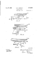
- Fig. l is a side elevation of a portion of a knitting machine constructed in accordance with the invention, the various parts not directly related to the invention being omitted for the sake of clearness;
- Fig. 2 is an enlarged fragmentary elevation showing the parts associated with the ratchets controlling the carrier for the intermediate gear- Figs. 3, 4 and 5 are enlarged fragmentary views showing details of the pawl and ratchet controlling mechanism; and
- Fig. 6 is a horizontal sectional View illustrating the driving gearing for the wrap finger supporting head and a modified arrangement for tensioning the carrier.
- the machine which is illustrated is similar to that disclosed in my said prior application and to that illustrated in the application of Stanley 'R. Shelmire, Serial No. 623,057, filed July 18, 1932, so far as the various controlling and operating is designed to produce a double sole in a stocking by the addition of a yarn in the sole of the foot portion, wrapping of the leg and instep being carried out in the manner described in said Shelmire application, the only addition to the wrapping operation involving the shogging of the wrap fingers relatively to the needles to produce This shogging is carried out in a manner generally resembling that of my prior application.
- the machine as illustrated comprises a needle cylinder 2 which carries needles 4 arranged in the usual fashion and provided with different length butts so that proper selection can.
- the shaft it carries at its upper end a gear t2 driving a pinion Ml carried by a shaft journalled in a bracket of the frame.
- the shaft carrying the pinion it is provided with a lower member of universal joint Hi, the upper member of which connected with one section of a two-part splined shaft it which at its upper end is connected through a universal joint similar to it with a shaft 22 which carries a pinion 24 meshing with a ring gear 26.
- the universal joints are of the conventional type which will maintain the pinions M and 24 in a definite angular relationship irrespective of movements of translation of 'Which is journalled a carrier 4%.
- the pinion 24 so long as its axis remains parallel with the axis of the pinion it. It will be noted that the universal joints together with the splined arrangement permit the axes to remain parallel in spite of the movements of the axis of the gear 24 about the axis of rotation of the needle cylinder as will be hereafter evident.
- the ring gear 26 is carried by the bobbin plate 28 which carries bearing ring rotating on the top of the bracket 32 which when in operative position forms an integral part of the machine frame, although it may be tilted as described in the Shelrnire application when the latch ring is raised or independently of said latch ring, the shaft [8 by its splined construction permitting this to occur.
- Secured to the bobbin plate is a tubular member 34% extending inside an opening in the bracket 32 which provides a bearing for it.
- the lower end of member 36 carries the wrap finger supporting head 36 which is slotted and formed to provide a pivotal support for wrap fingers 33 held therein in the usual fashion by a ping, patterning being obtained by the selection of needles.
- the bracket 32 is provided with an external bearing surface concentric with the axis of the wrap finger head and the needle cylinder on A lateral extension of the carrier 4E provides a journal for the shaft 22 and the pinion 24.
- the carrier is provided with an extension 42 to which are secured ratchet plates 45, 48 and 58 illustrated in elevation in Fig. 2 and in plan in Figs. 3, 4, and 5. From the latter it will be seen that the teeth 66 and 96 of the plates 46 and 59 are directed in one direction while the teeth 83 of the plate 48 are directed in the opposite direction.
- the carrier 48 is urged clockwise as viewed in plan by a weight 49 connected to the carrier through a spring 5! by a cord 46 passing over a ratchet plate 45 by means of a spring 64 connected between the pawl and a post carried by the lever 54.
- a pin 68 carried by the pawl is arranged to engage a cam it carried by a fixed bracket '52 so that the pawl is held out of contact with the teeth when in its retracted position to which it is urged by its spring 6!.
- the lever 54 is moved clockwise as viewed in Fig. 2 the pawl 62 will move to the right as shown in Fig. 3 so that it will engage a tooth of the ratchet 56 as the pin 63 rides off the cam 'Eil.
- the cam i6 is provided primarily to normally hold the pawl 62 away from the teeth to permit reverse movements of the carrier 40.
- a rod #4 carried by the lever 54 is provided with a spear-head 75 adapted to engage a cam it carried by a detent 18 mounted on a. fixed stud til carried by the bracket 32 and. urged by a spring 82 to bring its nose into engagement with teeth 84 of the ratchet plate 8.
- a lateral extension of the arm 54 pivotally supports a lever ll which is urged by a strong spring 81 into engagement with a stop pin 19' carried by the extension.
- the lever H is in horizontal ali nment with the sloping lefthand surface of the pawl as viewed in Fig. 4.
- the arrangement of the parts is such that as the rod 14 ad vances during forward movements of the pawl 62 the spear-head l5 engages the cam 15 to disengage the detent 18 from a tooth 84 just prior to the engagement of the pawl 62 with a tooth 35. As the spear-head moves further its point passes over the inward point of the cam 15 thereby releasing the detent 73 permitting it to again move between the teeth 3 1 as soon as the pawl 62 has advanced the carrier 40 to such extent as to move the last engaged tooth 84 beyond the nose of the pawl it. To insure that the pawl is moves inwardly the" lever H is arranged to engage it to provide a force in addition to that exerted by the spring 32.
- the pawl is accordingly in position to engage the next tooth 84 before the pawl 62 reaches its extreme forward position.
- the timing of these parts will be described in more detail hereafter.
- the detent it is not only provided for the purpose of properiy aligning the wrap fingers with the needles but additionally to hold the carrier in position during reciprocation at which time the weight 49 might be insufficient to hold it sufficiently rigidly to prevent objectionable vibration.
- the pawl E8 in the present instance has this function of the corresponding pawl in my prior application in addition to its more important function which will be brought out hereafter.
- detents 8E journalled upon the stud 88 are detents 8E of different lengths as will be evident from Fig. 5. These detents are arranged to alternately engage teeth 95 of the ratchet plate 59 to hold the same in opposition to the effort of the weight to.
- the detents 86 and 88 are yieldingly held in operative engagement with the teeth Q3 by means of springs 92 reacting between them and a fixed pin on the machine frame. It is to be noted that the angular spacing oi the teeth is double the spacing of the teeth 56.
- the lengths of pawls 86- and 88 are such that as they are alternately tripped the carrier to may move backwardly in stepsunder the action of weight through the angular spacing of teeth 56.
- the levers 54, 56 and 56 are controlled in the same manner as the corresponding levers illus' trated in my prior application. They are en.- gaged respectively by three levers indicated at pivoted on a common stud and urged in a clockwise direction as viewed in Fig. 1 by springs lot? to bring them into engagement with a stop post lot. At their lower ends the respective levers we are provided with adjustable contact screws 06 engageable by the ends of respective levers I88 which are selectively positioned to move either above or below a guard H8 by the action of a pivoted member H2 on their upwardly extending rear ends during their retracting strokes.
- the member H2 may be positioned in line with any selected one of the levers 38 by the rocking of its carrier lever I I4 pivoted on the post H5 and engageable by the member H6 controlled by lugs H8 on a pattern chain I21) which is intermittently advanced in the usual fashion by a pawl and ratchet mecha,
- the detent 18' is released from the tooth 34 in front of which it lies by the action of the spear-head 15 upon the cam 16.
- the detent 18 would not engage a tooth at this time but would have a very slight clearance therewith, the carrier being positioned by engagement of one of the detents 3% or 33 with a tooth 99.
- the pawl 62 engages a teeth 6% and ad vances the carrier against the action of the weight 48.
- the period of advance of the carrier is thus out down to such extent that wrapping is interrupted for only a relatively short time which in practice is found to be of the same order as the time during which wrapping must be interrupted to permit reverse movements of the carrier. Reversing of the carrier takes place by the alternate tripping of the pawls 3E and 88 and the effort of the weight 49.
- the pawl or detent 78 will yield to permit the teeth 84 to pass during such reverse shogging movements while the pawl 52 is held out of the path of teeth 66 by the cam Hi.
- the use of the weight 49 insures an even tension being exerted upon the detents and pawl 52 in all positions of movement of the carrier. Its action in this respect is very superior to that of the spring used in my prior arrangement because the tension of this spring changes very substantially during the movements of the carrier.
- the spring 5i interposed in the cable 4 serves to smooth out the intermittentmovements of the weight 49 which then, by reason of its inertia, relatively slowly follows the movements of the carrier. Swinging movements are thus minimized.
- Fig. 6 there is illustrated an arrangement in which a spring is used as the equivalent of the weight 49 to insure a uniform eifort tending to retract the carrier 4!].
- a bell crank i32 is pivoted at we to the extension 42 of the carrier w.
- This bell crank carries a roller i3 3 engaging a cam E36 carried by a fixed bracket l38 which may be connected to the bracket 32.
- a spring M0 reacts between the end of the other arm of the bell crank i152 and a fixed post M2 carried by abracket secured to the standard I I5 which may be used to support the main yarn bobbins.
- the cam I36 is suitably laid out so that in all positions of movement of the carrier ii the effort exermd upon the detents will be the same.
- the surface of the cam 36 engaging the roller I34 in the design shown very closely approaches a straight line being theoretically only slightly curved at its ends. By the use of other levers the same result may be effected but the corresponding cams in such cases may depart very considerably from straight lines.
- the tension may be maintained constant to thus secure proper operation.
- the shogging mechanism is applicable to a stationary needle cylinder machine in place of the shogging mechanism described in my Patent 1,892,702 dated January 3, 1933.
- a knitting machine including a rotatin needle cylinder, needles carried by the cylinder, wrap fingers arranged to feed wrap yarns to needles, a carrier for the fingers rotating with the needle cylinder, means for shogging the carrier relatively to the needle cylinder in steps corresponding to the angular spacing of adjacent needles, and mutually abutting means for positively arresting relative shogging movements in both directions.
- a knitting machine including a rotating needle cylinder, needles carried by the cylinder,
- Wrap fingers arranged to feed wrap yarns to needles, a carrier for the fingers rotating with the needle cylinder, means for shogging the carrier relativelyto the needle cylinder in steps corresponding to the angular spacing of adjacent needles, and mutually abutting means for positively arresting relative shogging movements in both directions when the wrap fingers are registered with the needles.
- a knitting machine including a rotating needle cylinder, needles carried by the cylinder,
- 'wrap fingers arranged to feed wrap yarns to needles, a carrier for the fingers rotating with the needle cylinder, means for positively shogging the carrier relatively to the needle cylinder in one direction, and mutually abutting means for positively arresting the relative shogging movements in that direction.
- a knitting machine including a needle cylinder, needles carried by the cylinder, wrap fingers arranged to feed wrap yarns to needles, 2, carrier for the fingers, and means for shogging the carrier relatively to the needle cylinder, said means including a ratchet member, a pawl engageable with the ratchet member to advance the same, and means for positively arresting the ratchet member while the pawl still tends to advance said member.
- a knitting machine including a needle cylinder, needles carried by the cylinder, wrap fingers arranged to feed wrap yarns to needles, a carrier for the fingers, and means for shogging the carrier relatively to the needle cylinder, said means including a ratchet member, a pawl engageable with the ratchet member to advance the same, and means for positively arresting the ratchet member while the pawl still tends to advance said member, said arresting means being released from the ratchet member prior to the beginning of the advance movement of the ratchet and being then rendered active prior to the attainment by the ratchet of its final position.
- a knitting machine including a needle cylinder, needles carried by the cylinder, wrap fingers arranged to feed wrap yarns to needles, a carrier for the fingers, and means for shogging the carrier relatively to the needle cylinder, said means including a ratchet member provided with two ratchet plates having teeth facing in opposite directions, a pawl engageable with teeth of one ratchet plate to advance the ratchet member, and a detent arranged to engage the teeth or" the other ratchet plate to positively arrest the movements of the ratchet member under the action of the pawl.
- a knitting machine including a needle cylinder, needles carried by the cylinder, wrap fingers arranged to feed wrap yarns to needles, a carrier for the fingers, and means for shogging the carrier relatively to the needle cylinder, said means including a ratchet member provided with two ratchet plates having teeth facing in opposite directions, a pawl engageable with teeth of one ratchet plate to advance the ratchet member, and a detent arranged to engage the teeth of the other ratchet plate to positively arrest the movements of the ratchet member under the action of the pawl while the pawl still tends to advance said member.
- a knitting machine including a needle cylinder, needles carried by the cylinder, wrap fingers arranged to feed wrap yarns to needles,
- carrier for the fingers and means for shogging the carrier relatively to the needle cylinder
- said means including a ratchet member provided with two ratchet plates having teeth facing in opposite directions, a pawl engageable with teeth of one ratchet plate to advance the ratchet member, and a detent arranged to engage the teeth of the other ratchet plate to positively arrest the movements of the ratchet member under the action of the pawl when the ratchet member has been advanced a sufiicient distance to accurately register the wrap fingers with needles to be wrapped.
- a knitting machine including a needle cylinder, needles carried by the cylinder, wrap fingear train whereby the carrier is shoggedrelager's arranged to feed wrap yarns to needles, a carrieriorthefingers,and means for shogging the carrier relatively to the needle cylinder, said means including a ratchet member, a pawl for imparting forward movements to the ratchet member, a detent arranged to positively limit forward movements of said member, and means for controlling the detent whereby it disengages the ratchet member prior to engagement of the pawl therewithand whereby the detent moves into position to arrest the ratchet member while the pawl still tends to advance said member.
- a knitting machine including a needle cylinder, needles carried by the cylinder, wrappawl therewith and whereby the detent moves into position to arrest the ratchet member while the pawl still tends to advance said member, the
- detent being normally in position to arrest forward movements of the ratchet member when shogging is not occurring.
- a knitting machine including a needle cylinder, needles carried by the cylinder, wrap fingers arranged to feed wrap yarns to needles, a carrier for the fingers, and means for shogging the carrier relatively to the needle cylinder, said means including detent means serving to stop and register the wrap fingers with needles when shoggingoccurs one direction and detent means serving to stop and register the wrap fingers with needles when shogging occurs in the opposite direction, said detent means normally preventing movement of the carrier in either direction.
- a knitting machine including a needle cylinder, needles carried by the cylinder, wrap fingers arranged to feed wrap yarns to needles, a carrier for the fingers, and means for shogging the carrier relatively to the needle cylinder, said means including detent means serving to stop and register the wrap fingers with needles when shogging occursin one direction and detent means serving to stop and register the wrap fingers with needles when shogging occurs in the opposite direction, both detent means including detents having fixed pivots.
- a knitting machine including a needle cylinder, needles carried by the cylinder, wrap fingers arranged to feed wrap yarns to needles, a carrier for the fingers, and means for shogging the carrier relatively to the needle cylinder, said means including means for yieldingly urging the carrier in one direction relatively to the needle cylinder, means for shogging the carrier against the action of the yielding means, and means for arresting the last named shogging movements, the positively arresting means serving to addie tionally prevent the carrier from moving in 0pposition to the yielding means when shogging is not taking place.
- A'knitting machine including a rotating needle cylinder, needles carried by the cylinder, wrap fingers arranged to feed wrap yarns to needles, a carrier for the fingers rotating with the needle cylinder, an epicyclic gear train between the cylinder and carrier whereby they rotate together, means for imparting limited step by step movements to an element of said epicyclic needle cylinder, needles carried by the cylinde'r, wrap fingers arranged to feed wrap yarns to needles, a carrier for the fingers rotating with the needle cylinder, an epicyclic gear train between the cylinder and carrier whereby they rotate together, means for imparting limited step by step movements to an element of said epicyclic gear train whereby the carrier is shogged relatively to the needle cylinder, said last means including means for yieldingly urging said element inone direction, means for advancing the element against the action of the yielding means, and means for positively arresting advancing movements of the element.
- a knitting machine including a rotating needle cylinder, needles carried by the cylinder, wrap fingers arranged to feed wrap yarns to needles, a carrier for the fingers rotating with the needle cylinder, an epicyclic gear train between the cylinder and carrier whereby they rotate together, means for imparting limited step by step movements to an element of said epicyclic gear train whereby the carrier is shogged-relatively to the needle cylinder, said last means including means for yieldingly urging said element in one direction, means for advancing the element against the action of the yielding means, means for positively arresting advancing movements of the element, and means for holding said element in definite positions against the action of the yielding means.
- a knitting machine including a rotating needle cylinder, needles carried by the cylinder, wrap fingers arranged to feed wrap yarns to needles, a carrier for the fingers rotating with the needle cylinder, an epicyclicgear train between the cylinder and carrier whereby they rotate toether, means for imparting limited step by step movements to an element of said epicyclic gear train whereby the carrier is shogged relatively to the needle cylinder, said last means including means for yieldingly urging said element in one direction, means for advancing the element against the action of the yielding means, and means for arresting advancing movements of the element, the arresting. means serving to additionally prevent the element from moving in opposition to the yielding means when shogging is not taking place.
- a knitting machine including a rotating needle cylinder, needles carried by the cylinder, wrap fingers arranged to feed wrap yarns to needles, a carrier for the fingers rotating with' the needle cylindenan epicyclic gear train between the cylinder and carrier whereby they rotate together, means for imparting-limited step by step movements to an element of said epicyclic gear train whereby the carrier is shogged relaneedle cylinder, needles carried by the cylinder,
- wrap fingers arranged to feed wrap yarns to needles, a carrier for the fingers rotating with the needle cylinder, an epicyclic gear train between the cylinder and carrier whereby they rotate together, means for imparting limited step by step movements to an element of said epicyclic gear train whereby the carrier is shogged relatively to the needle cylinder, and meansfor yieldingly-urging said element in one direction with substantially the same effort independently of its position within its range of movement.
- a knitting machine including a rotating needle cylinder, needles carried by the cylinder, wrap fingers arranged to feed wrap yarns to needles, a carrier for the fingers rotating with the needle cylinder, an epicyclic gear train between the cylinder and carrier whereby they rotate together, means for imparting limited step by step movements to an element of said epicyclic gear train whereby the carrier is shogged relatively to the needle cylinder, and means for yieldingly urging said element in one direction with substantially the same effort independently of its position within its range of movement, said last means including a weight.
- a knitting machine including a rotating needle cylinder, needles carried by the cylinder,
- wrap fingers arranged to feed wrap yarns to needles, a carrier for the fingers rotating with the needle cylinder, an epicyclic gear train between the cylinder and carrier whereby they to tate together, means for imparting limited step by step movements to an element of said epicyclic gear train whereby the carrier is shogged relatively to the needle cylinder, means for yieldingly urging said element in one direction with substantially the same efiort independently of its position within its range of movement, said last means including a weight, and a spring connected between the weight and element.
- a knitting machine including a rotating needle cylinder, needles carried by the cylinder, wrap fingers arranged to feed wrap yarns to needles, a carrier for the fingers rotating with the needle cylinder, an epicyclic gear train between the cylinder and carrier whereby they rotate together, means for imparting limited step by step movements to an element of said epicyclic gear train whereby the carrier is shogged relatively to the needle cylinder, and means for yieldingly urging said element in one direction with substantially the same efiort independently of its position within its range of movement, said last means including a spring and means for controlling the efiort exerted by the spring on the element.
Landscapes
- Engineering & Computer Science (AREA)
- Textile Engineering (AREA)
- Knitting Machines (AREA)
Description
135. H. E. HOUSEMAN 2,1,3
KNITTING MACHINE Filed May 2, 1953 5 Sheets-Sheet l 770 A E'YJ Aug 27, 1935. H. E. HQUSEMAN 3 3 I KNITTING MACHINE Filed May 2, 1933 3 Sheets-Sheet 2 @[f 4/ My x v Array) 5Y5.
Aug. 27, W35. H. E. HOUSEM'AN KNITTING MACHINE W 3 Sheets-Sheet 3 Filed May 2, 1953 five 5mm) flarola/ fi ozzaaman W/T/VESS:
them to wrap various needles.
Patented Aug. 27, 1935 hlITED STATES PATENT OFFIQE 2,012,309 KNITTING MACHINE Harold E. Houseman, Edge Moor, Del, assignor to Standard-Trump Bros. Machine Company,
Wilmington, DeL, a corporation of Delaware Application May 2, 1933, Serial No. 668,924
22 Claims. (01. 66-135) tion is also applicable for the shogging of wrap fingers in a stationary'needle machine.
In my application, Serial No. 653,229, filed January 24, 1933, there is described an arrangement whereby shogging movements may be imparted to wrap fingers while the fingers are rotating with the rotating needle cylinder so as to produce an advance or lag of the fingers to cause each of In this machine gearing in the form of an epicyclic train connects the needle cylinder with the wrap finger supporthead so that they are rotated in unison so long as the arm of the epicyclic gear train is fixed in pcsiton, this arm comprising acarrier mounted concentrically with the wrap finger head. To produce shagging this carrier is given intermittent step movements in one direction positively under the action of a pawl and in the other direction by a tensioned spring operating upon release of the carrier by detents engaging ratchet teeth thereon. The ratchet teeth of the carrier are so indexed that when theyare properly engaged by the detents the wrap fingers are in positions to cooperate with needles. Whenever the carrier is intermediate the positions determined'bythe engagement of the detents with ratchet teeth the wrap fingers are out of alignment with needles and at such times dare not be moved through the needle circle. During the shogging movements, namely, when the carrier is being either advanced by the pawl or retracted by the spring, no wrapping may take place and accordingly in a stocking prcduced by such machine there is necessarily an unwrapped panel whose width depends upon the time necessary for the production of the shogging movements.
in the machine as disclosed in my prior application the movements of the carrier under the action of the spring take place very rapidly so that when shogging takes place in the corresponding direction there no need for any prolonged interruption of the wrapping operations. For example, in a 2% needle machine having a 3 inch cylinder it is found that the panel required by the reverse movements of the carrier need be no more than about twenty needles in width.
The machine of my prior application, however, considerably larger unwrapped panels to taize care of the forward shagging if this is to take place in a reliable fashion. The pawl which.
serves to drive the carrier forwardly is actuated through a system of levers by a pattern mechanism located at a relatively remote position, this arrangement being adopted for convenience in design. There is considerable lost motion, therefore, between the pattern mechanism and the driving pawl due to clearances and deflections of the connecting parts. Furthermore, the quicker the movement imparted to the carrier the more likelihood there is that its inertia will carry it to some extent beyond the proper position for alignment of a wrap finger with a needle. To secure reliability of operation the adjustment in my prior mechanism was made such that the driving pawl imparting forward movements to the carrier was given a stroke in excess of that which would be required to secure the cooperation of a wrap finger with another needle; that is, the pawl was given a stroke substantially in excess of the spacing between the ratchet teeth with which it is engaged, the stroke being greater than the distance between adjacent teeth but less than twice this distance. Inasmuch as the return stroke of the pawl occurred necessarily fairly leisurely, there -Was a period during which wrapping could not take place corresponding in length from the time the pawl first engaged a ratchet tooth to the time when on its retracting stroke it disengaged such teeth by reason of the holding of the carrier in its properly advanced position by a detent. This action in my prior machine corresponded to a .rnovement of a cylinder of the type indicated above through the angular distance of about forty needles. The panel which had to be free from wrapping was therefore approximately twice the width required by the retracting operation.
It is the object of the present invention to pro- .vide a shogging mechanism applicable to a machine of this character in which the period of advance of the wrap fingers relative to the needles is substantially shortened and corresponds to the short period required for reverse movements. The invention is also applicable to the production of shogging in machines of the stationary needle cylinder type in which the same problems arise though to a smaller degree.
In my prior machine reverse movements of a carrier were imparted by means of a spring secured directly between the carrier and a fixed part of the machine. To secure proper operation it is necessary that the tension exerted by thecarrier upon the detents and driving pawl should be of a proper amount. By the use of a spring, as in my prior mechanism, the tension was so increased and decreased from a mean zigzag designs.
value during movements of the carrier from one extreme to the other of its are that proper operation would not at times take place at the extremes of its movement. It is a further object of the invention to provide means for tensioning the carrier which will cause it to exert a substantially uniform pressure upon the detents throughout its entire range of movement.
Ihe above objects and more specific ones relating to details of construction will be apparent from the following description read in conjunction with the accompanying drawings in which:
Fig. l is a side elevation of a portion of a knitting machine constructed in accordance with the invention, the various parts not directly related to the invention being omitted for the sake of clearness;
Fig. 2 is an enlarged fragmentary elevation showing the parts associated with the ratchets controlling the carrier for the intermediate gear- Figs. 3, 4 and 5 are enlarged fragmentary views showing details of the pawl and ratchet controlling mechanism; and
Fig. 6 is a horizontal sectional View illustrating the driving gearing for the wrap finger supporting head and a modified arrangement for tensioning the carrier.
The machine which is illustrated is similar to that disclosed in my said prior application and to that illustrated in the application of Stanley 'R. Shelmire, Serial No. 623,057, filed July 18, 1932, so far as the various controlling and operating is designed to produce a double sole in a stocking by the addition of a yarn in the sole of the foot portion, wrapping of the leg and instep being carried out in the manner described in said Shelmire application, the only addition to the wrapping operation involving the shogging of the wrap fingers relatively to the needles to produce This shogging is carried out in a manner generally resembling that of my prior application. The machine as illustrated comprises a needle cylinder 2 which carries needles 4 arranged in the usual fashion and provided with different length butts so that proper selection can.
to produce both rotation and reciprocation thereof.' The shaft it carries at its upper end a gear t2 driving a pinion Ml carried by a shaft journalled in a bracket of the frame. The shaft carrying the pinion it is provided with a lower member of universal joint Hi, the upper member of which connected with one section of a two-part splined shaft it which at its upper end is connected through a universal joint similar to it with a shaft 22 which carries a pinion 24 meshing with a ring gear 26. V The universal joints are of the conventional type which will maintain the pinions M and 24 in a definite angular relationship irrespective of movements of translation of 'Which is journalled a carrier 4%.
the pinion 24 so long as its axis remains parallel with the axis of the pinion it. It will be noted that the universal joints together with the splined arrangement permit the axes to remain parallel in spite of the movements of the axis of the gear 24 about the axis of rotation of the needle cylinder as will be hereafter evident.
The ring gear 26 is carried by the bobbin plate 28 which carries bearing ring rotating on the top of the bracket 32 which when in operative position forms an integral part of the machine frame, although it may be tilted as described in the Shelrnire application when the latch ring is raised or independently of said latch ring, the shaft [8 by its splined construction permitting this to occur. Secured to the bobbin plate is a tubular member 34% extending inside an opening in the bracket 32 which provides a bearing for it. The lower end of member 36 carries the wrap finger supporting head 36 which is slotted and formed to provide a pivotal support for wrap fingers 33 held therein in the usual fashion by a ping, patterning being obtained by the selection of needles.
The bracket 32 is provided with an external bearing surface concentric with the axis of the wrap finger head and the needle cylinder on A lateral extension of the carrier 4E provides a journal for the shaft 22 and the pinion 24. By reason of the concentric mounting of the carrier G59 and the gear 26 it will be seen that the pinion 2:3 will remain in mesh with said gear irrespective of the position of the carrier.
At the side of the machine illustrated in Fig. 1, the carrier is provided with an extension 42 to which are secured ratchet plates 45, 48 and 58 illustrated in elevation in Fig. 2 and in plan in Figs. 3, 4, and 5. From the latter it will be seen that the teeth 66 and 96 of the plates 46 and 59 are directed in one direction while the teeth 83 of the plate 48 are directed in the opposite direction. The carrier 48 is urged clockwise as viewed in plan by a weight 49 connected to the carrier through a spring 5! by a cord 46 passing over a ratchet plate 45 by means of a spring 64 connected between the pawl and a post carried by the lever 54. A pin 68 carried by the pawl is arranged to engage a cam it carried by a fixed bracket '52 so that the pawl is held out of contact with the teeth when in its retracted position to which it is urged by its spring 6!. As the lever 54 is moved clockwise as viewed in Fig. 2 the pawl 62 will move to the right as shown in Fig. 3 so that it will engage a tooth of the ratchet 56 as the pin 63 rides off the cam 'Eil. The cam i6 is provided primarily to normally hold the pawl 62 away from the teeth to permit reverse movements of the carrier 40.
A rod # 4 carried by the lever 54 is provided with a spear-head 75 adapted to engage a cam it carried by a detent 18 mounted on a. fixed stud til carried by the bracket 32 and. urged by a spring 82 to bring its nose into engagement with teeth 84 of the ratchet plate 8. A lateral extension of the arm 54 pivotally supports a lever ll which is urged by a strong spring 81 into engagement with a stop pin 19' carried by the extension. The lever H is in horizontal ali nment with the sloping lefthand surface of the pawl as viewed in Fig. 4. The arrangement of the parts is such that as the rod 14 ad vances during forward movements of the pawl 62 the spear-head l5 engages the cam 15 to disengage the detent 18 from a tooth 84 just prior to the engagement of the pawl 62 with a tooth 35. As the spear-head moves further its point passes over the inward point of the cam 15 thereby releasing the detent 73 permitting it to again move between the teeth 3 1 as soon as the pawl 62 has advanced the carrier 40 to such extent as to move the last engaged tooth 84 beyond the nose of the pawl it. To insure that the pawl is moves inwardly the" lever H is arranged to engage it to provide a force in addition to that exerted by the spring 32. The pawl is accordingly in position to engage the next tooth 84 before the pawl 62 reaches its extreme forward position. The timing of these parts will be described in more detail hereafter. The detent it is not only provided for the purpose of properiy aligning the wrap fingers with the needles but additionally to hold the carrier in position during reciprocation at which time the weight 49 might be insufficient to hold it sufficiently rigidly to prevent objectionable vibration. The pawl E8 in the present instance has this function of the corresponding pawl in my prior application in addition to its more important function which will be brought out hereafter.
Also journalled upon the stud 88 are detents 8E of different lengths as will be evident from Fig. 5. These detents are arranged to alternately engage teeth 95 of the ratchet plate 59 to hold the same in opposition to the effort of the weight to. The detents 86 and 88 are yieldingly held in operative engagement with the teeth Q3 by means of springs 92 reacting between them and a fixed pin on the machine frame. It is to be noted that the angular spacing oi the teeth is double the spacing of the teeth 56. The lengths of pawls 86- and 88 are such that as they are alternately tripped the carrier to may move backwardly in stepsunder the action of weight through the angular spacing of teeth 56.
Members 9% and 96 carried by the upper ends of levers E56 and 53 respectively. are designed to engage the pawls 85 and 58 respectively to trip them out of engagement with the teeth 92 The operation is such that the members 94 and Si) are alternately moved so that backward steps of proper angular amount are produced by the alternate freeing of the detents 8G and 83 from the teeth 95.
The levers 54, 56 and 56 are controlled in the same manner as the corresponding levers illus' trated in my prior application. They are en.- gaged respectively by three levers indicated at pivoted on a common stud and urged in a clockwise direction as viewed in Fig. 1 by springs lot? to bring them into engagement with a stop post lot. At their lower ends the respective levers we are provided with adjustable contact screws 06 engageable by the ends of respective levers I88 which are selectively positioned to move either above or below a guard H8 by the action of a pivoted member H2 on their upwardly extending rear ends during their retracting strokes. The member H2 may be positioned in line with any selected one of the levers 38 by the rocking of its carrier lever I I4 pivoted on the post H5 and engageable by the member H6 controlled by lugs H8 on a pattern chain I21) which is intermittently advanced in the usual fashion by a pawl and ratchet mecha,
nism driven by the main driving mechanism and controlled by suitable cams carried by the main cam disc 122. i
The operation of forwardly shogging the wrap fingers relatively to the needles is effected by a stroke of the lever 54 under the action of the corresponding lever 1118 selected by a lug of proper height on the pattern chain. The stroke imparted to the corresponding lever Hill is such that if there were no interruption to the forward movement of the pawl 52 the pawl would advance to carry the plate 46 through an angular distance greater than the angular spacing between adjacent teeth '36. As will be pointed out, such movement is prevented, the excess movement imparted to it!) being taken up in a slight springing of the levers we and 54. As the lever 54 begins its forward movement and before the pawl E32 engages a tooth 65 the detent 18' is released from the tooth 34 in front of which it lies by the action of the spear-head 15 upon the cam 16. In general, the detent 18 would not engage a tooth at this time but would have a very slight clearance therewith, the carrier being positioned by engagement of one of the detents 3% or 33 with a tooth 99. As soon as the detent 78 is moved out of the path of the tooth 3 the pawl 62 engages a teeth 6% and ad vances the carrier against the action of the weight 48. As soon as the tooth 8 previously lying substantially against the pawl ill moves therebeyond the pawl i8 is released and positively forced into the path of the next tooth 8% by the actions of the spring 32 and the spring tensioned lever ll. Thereafter the'pawl 62continues to advance the carrier, this advance stopping when the next tooth 34 engages the pawl '53. The excess movement imparted to the lever '93 is then taken up by springing of the parts. By providing for this there is definite assurance hat a tooth 84 will be engaged with the detent 78. As engagement of a tooth 84 with the detent l8 takes place one of the pawls 88 or 86 i will drop in front of the next tooth 93 so that when the pawl 52 is withdrawn one of these detents will hold the carrier in its advanced posi tion. In view of the action of snubbing pawl or detent it which substantially tends to hold the carrier in the same position as the detents 86 and. 28, the wrap fingers are positioned relatively to the needles for wrapping even before the forward eiiort applied to the pawl-52 has ceased and, of course, considerably before it is permitted to move in its retracting stroke. The period of advance of the carrier is thus out down to such extent that wrapping is interrupted for only a relatively short time which in practice is found to be of the same order as the time during which wrapping must be interrupted to permit reverse movements of the carrier. Reversing of the carrier takes place by the alternate tripping of the pawls 3E and 88 and the effort of the weight 49.
The pawl or detent 78 will yield to permit the teeth 84 to pass during such reverse shogging movements while the pawl 52 is held out of the path of teeth 66 by the cam Hi. The use of the weight 49 insures an even tension being exerted upon the detents and pawl 52 in all positions of movement of the carrier. Its action in this respect is very superior to that of the spring used in my prior arrangement because the tension of this spring changes very substantially during the movements of the carrier. The spring 5i interposed in the cable 4 serves to smooth out the intermittentmovements of the weight 49 which then, by reason of its inertia, relatively slowly follows the movements of the carrier. Swinging movements are thus minimized.
In Fig. 6 there is illustrated an arrangement in which a spring is used as the equivalent of the weight 49 to insure a uniform eifort tending to retract the carrier 4!]. In this arrangement a bell crank i32 is pivoted at we to the extension 42 of the carrier w. This bell crank carries a roller i3 3 engaging a cam E36 carried by a fixed bracket l38 which may be connected to the bracket 32. A spring M0 reacts between the end of the other arm of the bell crank i152 and a fixed post M2 carried by abracket secured to the standard I I5 which may be used to support the main yarn bobbins. The cam I36 is suitably laid out so that in all positions of movement of the carrier ii the effort exermd upon the detents will be the same. The surface of the cam 36 engaging the roller I34 in the design shown very closely approaches a straight line being theoretically only slightly curved at its ends. By the use of other levers the same result may be effected but the corresponding cams in such cases may depart very considerably from straight lines. By the use of either the weight or the spring arrangement of Fig. 6 the tension may be maintained constant to thus secure proper operation.
It will be clear that numerous changes may be made in the embodiment of the invention without departing from the scope thereof as defined in the following claims. For example, the shogging mechanism is applicable to a stationary needle cylinder machine in place of the shogging mechanism described in my Patent 1,892,702 dated January 3, 1933.
What I claim and desire to protect by Letters Patent is: I
1. A knitting machine including a rotatin needle cylinder, needles carried by the cylinder, wrap fingers arranged to feed wrap yarns to needles, a carrier for the fingers rotating with the needle cylinder, means for shogging the carrier relatively to the needle cylinder in steps corresponding to the angular spacing of adjacent needles, and mutually abutting means for positively arresting relative shogging movements in both directions. a
2. A knitting machine including a rotating needle cylinder, needles carried by the cylinder,
Wrap fingers arranged to feed wrap yarns to needles, a carrier for the fingers rotating with the needle cylinder, means for shogging the carrier relativelyto the needle cylinder in steps corresponding to the angular spacing of adjacent needles, and mutually abutting means for positively arresting relative shogging movements in both directions when the wrap fingers are registered with the needles.
3. A knitting machine including a rotating needle cylinder, needles carried by the cylinder,
'wrap fingers arranged to feed wrap yarns to needles, a carrier for the fingers rotating with the needle cylinder, means for positively shogging the carrier relatively to the needle cylinder in one direction, and mutually abutting means for positively arresting the relative shogging movements in that direction.
l. A knitting machine including a needle cylinder, needles carried by the cylinder, wrap fingers arranged to feed wrap yarns to needles, 2, carrier for the fingers, and means for shogging the carrier relatively to the needle cylinder, said means including a ratchet member, a pawl engageable with the ratchet member to advance the same, and means for positively arresting the ratchet member while the pawl still tends to advance said member.
5. A knitting machine including a needle cylinder, needles carried by the cylinder, wrap fingers arranged to feed wrap yarns to needles, a carrier for the fingers, and means for shogging the carrier relatively to the needle cylinder, said means including a ratchet member, a pawl engageable with the ratchet member to advance the same, and means for positively arresting the ratchet member while the pawl still tends to advance said member, said arresting means being released from the ratchet member prior to the beginning of the advance movement of the ratchet and being then rendered active prior to the attainment by the ratchet of its final position.
6. A knitting machine including a needle cylinder, needles carried by the cylinder, wrap fingers arranged to feed wrap yarns to needles, a carrier for the fingers, and means for shogging the carrier relatively to the needle cylinder, said means including a ratchet member provided with two ratchet plates having teeth facing in opposite directions, a pawl engageable with teeth of one ratchet plate to advance the ratchet member, and a detent arranged to engage the teeth or" the other ratchet plate to positively arrest the movements of the ratchet member under the action of the pawl.
7. A knitting machine including a needle cylinder, needles carried by the cylinder, wrap fingers arranged to feed wrap yarns to needles, a carrier for the fingers, and means for shogging the carrier relatively to the needle cylinder, said means including a ratchet member provided with two ratchet plates having teeth facing in opposite directions, a pawl engageable with teeth of one ratchet plate to advance the ratchet member, and a detent arranged to engage the teeth of the other ratchet plate to positively arrest the movements of the ratchet member under the action of the pawl while the pawl still tends to advance said member.
8. A knitting machine including a needle cylinder, needles carried by the cylinder, wrap fingers arranged to feed wrap yarns to needles,
2, carrier for the fingers, and means for shogging the carrier relatively to the needle cylinder, said means including a ratchet member provided with two ratchet plates having teeth facing in opposite directions, a pawl engageable with teeth of one ratchet plate to advance the ratchet member, and a detent arranged to engage the teeth of the other ratchet plate to positively arrest the movements of the ratchet member under the action of the pawl when the ratchet member has been advanced a sufiicient distance to accurately register the wrap fingers with needles to be wrapped.
9. A knitting machine including a needle cylinder, needles carried by the cylinder, wrap fingear train whereby the carrier is shoggedrelager's arranged to feed wrap yarns to needles, a carrieriorthefingers,and means for shogging the carrier relatively to the needle cylinder, said means including a ratchet member, a pawl for imparting forward movements to the ratchet member, a detent arranged to positively limit forward movements of said member, and means for controlling the detent whereby it disengages the ratchet member prior to engagement of the pawl therewithand whereby the detent moves into position to arrest the ratchet member while the pawl still tends to advance said member.
iii. A knitting machine including a needle cylinder, needles carried by the cylinder, wrappawl therewith and whereby the detent moves into position to arrest the ratchet member while the pawl still tends to advance said member, the
detent being normally in position to arrest forward movements of the ratchet member when shogging is not occurring.
11. A knitting machine including a needle cylinder, needles carried by the cylinder, wrap fingers arranged to feed wrap yarns to needles, a carrier for the fingers, and means for shogging the carrier relatively to the needle cylinder, said means including detent means serving to stop and register the wrap fingers with needles when shoggingoccurs one direction and detent means serving to stop and register the wrap fingers with needles when shogging occurs in the opposite direction, said detent means normally preventing movement of the carrier in either direction.
12. A knitting machine including a needle cylinder, needles carried by the cylinder, wrap fingers arranged to feed wrap yarns to needles, a carrier for the fingers, and means for shogging the carrier relatively to the needle cylinder, said means including detent means serving to stop and register the wrap fingers with needles when shogging occursin one direction and detent means serving to stop and register the wrap fingers with needles when shogging occurs in the opposite direction, both detent means including detents having fixed pivots.
13. A knitting machine including a needle cylinder, needles carried by the cylinder, wrap fingers arranged to feed wrap yarns to needles, a carrier for the fingers, and means for shogging the carrier relatively to the needle cylinder, said means including means for yieldingly urging the carrier in one direction relatively to the needle cylinder, means for shogging the carrier against the action of the yielding means, and means for arresting the last named shogging movements, the positively arresting means serving to addie tionally prevent the carrier from moving in 0pposition to the yielding means when shogging is not taking place.
14. A'knitting machine including a rotating needle cylinder, needles carried by the cylinder, wrap fingers arranged to feed wrap yarns to needles, a carrier for the fingers rotating with the needle cylinder, an epicyclic gear train between the cylinder and carrier whereby they rotate together, means for imparting limited step by step movements to an element of said epicyclic needle cylinder, needles carried by the cylinde'r, wrap fingers arranged to feed wrap yarns to needles, a carrier for the fingers rotating with the needle cylinder, an epicyclic gear train between the cylinder and carrier whereby they rotate together, means for imparting limited step by step movements to an element of said epicyclic gear train whereby the carrier is shogged relatively to the needle cylinder, said last means including means for yieldingly urging said element inone direction, means for advancing the element against the action of the yielding means, and means for positively arresting advancing movements of the element.
A knitting machine including a rotating needle cylinder, needles carried by the cylinder, wrap fingers arranged to feed wrap yarns to needles, a carrier for the fingers rotating with the needle cylinder, an epicyclic gear train between the cylinder and carrier whereby they rotate together, means for imparting limited step by step movements to an element of said epicyclic gear train whereby the carrier is shogged-relatively to the needle cylinder, said last means including means for yieldingly urging said element in one direction, means for advancing the element against the action of the yielding means, means for positively arresting advancing movements of the element, and means for holding said element in definite positions against the action of the yielding means.
17. A knitting machine including a rotating needle cylinder, needles carried by the cylinder, wrap fingers arranged to feed wrap yarns to needles, a carrier for the fingers rotating with the needle cylinder, an epicyclicgear train between the cylinder and carrier whereby they rotate toether, means for imparting limited step by step movements to an element of said epicyclic gear train whereby the carrier is shogged relatively to the needle cylinder, said last means including means for yieldingly urging said element in one direction, means for advancing the element against the action of the yielding means, and means for arresting advancing movements of the element, the arresting. means serving to additionally prevent the element from moving in opposition to the yielding means when shogging is not taking place.
18. A knitting machine including a rotating needle cylinder, needles carried by the cylinder, wrap fingers arranged to feed wrap yarns to needles, a carrier for the fingers rotating with' the needle cylindenan epicyclic gear train between the cylinder and carrier whereby they rotate together, means for imparting-limited step by step movements to an element of said epicyclic gear train whereby the carrier is shogged relaneedle cylinder, needles carried by the cylinder,
wrap fingers arranged to feed wrap yarns to needles, a carrier for the fingers rotating with the needle cylinder, an epicyclic gear train between the cylinder and carrier whereby they rotate together, means for imparting limited step by step movements to an element of said epicyclic gear train whereby the carrier is shogged relatively to the needle cylinder, and meansfor yieldingly-urging said element in one direction with substantially the same effort independently of its position within its range of movement.
20. A knitting machine including a rotating needle cylinder, needles carried by the cylinder, wrap fingers arranged to feed wrap yarns to needles, a carrier for the fingers rotating with the needle cylinder, an epicyclic gear train between the cylinder and carrier whereby they rotate together, means for imparting limited step by step movements to an element of said epicyclic gear train whereby the carrier is shogged relatively to the needle cylinder, and means for yieldingly urging said element in one direction with substantially the same effort independently of its position within its range of movement, said last means including a weight.
21. A knitting machine including a rotating needle cylinder, needles carried by the cylinder,
wrap fingers arranged to feed wrap yarns to needles, a carrier for the fingers rotating with the needle cylinder, an epicyclic gear train between the cylinder and carrier whereby they to tate together, means for imparting limited step by step movements to an element of said epicyclic gear train whereby the carrier is shogged relatively to the needle cylinder, means for yieldingly urging said element in one direction with substantially the same efiort independently of its position within its range of movement, said last means including a weight, and a spring connected between the weight and element.
22. A knitting machine including a rotating needle cylinder, needles carried by the cylinder, wrap fingers arranged to feed wrap yarns to needles, a carrier for the fingers rotating with the needle cylinder, an epicyclic gear train between the cylinder and carrier whereby they rotate together, means for imparting limited step by step movements to an element of said epicyclic gear train whereby the carrier is shogged relatively to the needle cylinder, and means for yieldingly urging said element in one direction with substantially the same efiort independently of its position within its range of movement, said last means including a spring and means for controlling the efiort exerted by the spring on the element.
HAROLD E. HOUSEMAN.
Priority Applications (1)
| Application Number | Priority Date | Filing Date | Title |
|---|---|---|---|
| US668924A US2012309A (en) | 1933-01-24 | 1933-05-02 | Knitting machine |
Applications Claiming Priority (2)
| Application Number | Priority Date | Filing Date | Title |
|---|---|---|---|
| US422063XA | 1933-01-24 | 1933-01-24 | |
| US668924A US2012309A (en) | 1933-01-24 | 1933-05-02 | Knitting machine |
Publications (1)
| Publication Number | Publication Date |
|---|---|
| US2012309A true US2012309A (en) | 1935-08-27 |
Family
ID=26718986
Family Applications (1)
| Application Number | Title | Priority Date | Filing Date |
|---|---|---|---|
| US668924A Expired - Lifetime US2012309A (en) | 1933-01-24 | 1933-05-02 | Knitting machine |
Country Status (1)
| Country | Link |
|---|---|
| US (1) | US2012309A (en) |
-
1933
- 1933-05-02 US US668924A patent/US2012309A/en not_active Expired - Lifetime
Similar Documents
| Publication | Publication Date | Title |
|---|---|---|
| US2012309A (en) | Knitting machine | |
| US3050972A (en) | Take-up mechanism for knitting machines | |
| US2196073A (en) | Means for controlling patterning and other operations of knitting machines | |
| US2309091A (en) | Carrier bar control mechanism | |
| US2043852A (en) | Knitting machine | |
| US2217521A (en) | Knitting machine | |
| US1637373A (en) | Work feed for sewing machines | |
| US2402200A (en) | Method of and mechanism for widening fabric on flat knitting machines | |
| US1218073A (en) | Knitting-machine. | |
| US1198448A (en) | Take-up for circular-knitting machines. | |
| US2004219A (en) | Automatically variable tensioning device for draw-off reels | |
| US2035960A (en) | Lace attachment for knitting machines | |
| US1775033A (en) | Island | |
| US1008752A (en) | Striping and embroidering mechanism for knitting-machines. | |
| US1873502A (en) | Circular knitting machine | |
| US2118815A (en) | Knitting machine | |
| US1484381A (en) | serra | |
| US1915415A (en) | Automatic loop variation compensating mechanism for knitting machines | |
| US2049887A (en) | Full fashioned knitting machine | |
| US1725150A (en) | Knitting machine | |
| US2180241A (en) | Bkake means for yarns | |
| US2828617A (en) | Circular knitting machines | |
| US1718327A (en) | Mechanism for transferring knitted webs | |
| US2012310A (en) | Knitting machine | |
| US2045617A (en) | Knitting mechanism |