US20120249758A1 - Electric apparatus and control method of indicator - Google Patents
Electric apparatus and control method of indicator Download PDFInfo
- Publication number
- US20120249758A1 US20120249758A1 US13/427,535 US201213427535A US2012249758A1 US 20120249758 A1 US20120249758 A1 US 20120249758A1 US 201213427535 A US201213427535 A US 201213427535A US 2012249758 A1 US2012249758 A1 US 2012249758A1
- Authority
- US
- United States
- Prior art keywords
- indicator
- camera
- controller
- indication
- cameras
- Prior art date
- Legal status (The legal status is an assumption and is not a legal conclusion. Google has not performed a legal analysis and makes no representation as to the accuracy of the status listed.)
- Abandoned
Links
Images


Classifications
-
- H—ELECTRICITY
- H04—ELECTRIC COMMUNICATION TECHNIQUE
- H04N—PICTORIAL COMMUNICATION, e.g. TELEVISION
- H04N13/00—Stereoscopic video systems; Multi-view video systems; Details thereof
- H04N13/30—Image reproducers
-
- H—ELECTRICITY
- H04—ELECTRIC COMMUNICATION TECHNIQUE
- H04N—PICTORIAL COMMUNICATION, e.g. TELEVISION
- H04N23/00—Cameras or camera modules comprising electronic image sensors; Control thereof
- H04N23/60—Control of cameras or camera modules
- H04N23/61—Control of cameras or camera modules based on recognised objects
- H04N23/611—Control of cameras or camera modules based on recognised objects where the recognised objects include parts of the human body
-
- H—ELECTRICITY
- H04—ELECTRIC COMMUNICATION TECHNIQUE
- H04N—PICTORIAL COMMUNICATION, e.g. TELEVISION
- H04N13/00—Stereoscopic video systems; Multi-view video systems; Details thereof
- H04N13/20—Image signal generators
- H04N13/204—Image signal generators using stereoscopic image cameras
- H04N13/239—Image signal generators using stereoscopic image cameras using two two-dimensional [2D] image sensors having a relative position equal to or related to the interocular distance
Definitions
- FIG. 1 is a perspective view of a personal computer 100 according to a first embodiment.
- FIG. 2 is a schematic block diagram showing an example of a system configuration for controlling the indicator 50 .
- FIG. 3 is a flowchart showing an example of processing operations of the controller 200 .
- FIG. 4 is a table showing a relationship between the indication of the indicator 50 and the operation status of the personal computer 100 .
- FIG. 5 is a perspective view of a personal computer 101 according to a second embodiment.
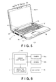
- FIG. 6 is a schematic block diagram showing an example of a system configuration for controlling the indicator 50 .
- FIG. 7 is a flowchart showing an example of processing operations of the controller 201 .
- FIG. 8 is a table showing a relationship between the indication of the indicator 50 and the operation status of the personal computer 101 .
- FIG. 9 is a perspective view of a personal computer 102 according to a third embodiment.
- FIG. 11 is a flowchart showing an example of processing operations of the controller 202 .
- FIG. 12 is a table showing a relationship between the indication of the indicator 50 and the operation status of the personal computer 102 .
- an electric apparatus has a camera or a plurality of cameras, an indicator, and a first controller.
- the first controller is configured to switch an indication of the indicator according to whether the camera performs photographing and whether to recognize a user's eye based on an image photographed by the camera.
- FIG. 1 is a perspective view of a personal computer 100 according to a first embodiment.
- the personal computer 100 has a computer body 10 , a display unit 20 , a camera 30 , a microphone 40 and an indicator 50 .
- the computer body 10 has a thin box-shaped case 11 .
- a keyboard 12 On the case 11 arranged are a keyboard 12 , a touch pad 13 and power button 14 which receive the user's operation, speakers 15 , USB (Universal Serial Bus) terminals 16 and so on.
- a CPU Central Processing Unit
- a memory On the case 11 arranged are a CPU (Central Processing Unit), a memory, an HDD (Hard Disk Drive) and an optical disk drive and so on (not shown).
- HDD Hard Disk Drive
- the keyboard 12 is an input device for generating signals indicative of operation characteristics such as character-entering and icon-selection.
- the touch pad 13 is a pointing device for generating signals indicative of operation characteristics such as screen-transition, cursor-motion and icon-selection.
- the power button 14 is a switch for on/off-controlling the power of the electric apparatus 100 .
- the CPU mounted in the computer body 10 executes a program stored in the hard disk to reproduce video signals stored in, for example, the hard disk, an optical disk such as a DVD (Digital Versatile Disk), an HD DVD (High Definition DVD), a BD (Blu-ray Disk) inserted in the optical disk device, or a USB storage device connected to the USB terminal 16 .
- an optical disk such as a DVD (Digital Versatile Disk), an HD DVD (High Definition DVD), a BD (Blu-ray Disk) inserted in the optical disk device, or a USB storage device connected to the USB terminal 16 .
- the computer body 10 outputs multiple parallax images viewed from different viewpoints to the display unit 20 so that the user can view the image stereoscopically without glasses.
- the parallax images can be generated using the depth information.
- the depth information can be calculated by analyzing the video signal to generate the parallax images.
- nine parallax images viewed from nine viewpoints arranged in a horizontal direction may be generated in order to display a three-dimensional image more naturally.
- the computer body 10 has a controller (not shown), which will be described in detail below, for controlling the display unit 20 , the camera 30 and the indicator 50 .
- the controller is, for example, stored in the hard disk as a computer program.
- the display unit 20 is rotatably attached on the computer body 10 via a hinge (not shown).
- the display unit 20 has a liquid crystal panel (display) 21 and a filter (outputting module) 22 .
- the reproduced multiple parallax images are simultaneously displayed on the liquid crystal panel 21 .
- the filter 22 is, for example, a liquid crystal filter, and controls an output direction from the liquid crystal panel 21 by deflecting the liquid crystal material.
- the filter 22 is arranged facing the liquid crystal panel 21 , and outputs the parallax images displayed on the liquid crystal panel 21 to a specific direction. That is, the filter 22 outputs one of the multiple parallax images to the right eye of the user, and another one of the multiple parallax images to the left eye. By viewing different parallax images with the right eye and the left eye, the user can view the image stereoscopically.
- the output direction of the filter 22 can be controlled by the controller, which will be described below.
- the camera 30 is arranged above the display unit 20 , for example.
- the camera 30 photographs a predetermined area to provide the photographed image to the controller.
- the image photographed by the camera 30 can be displayed on the liquid crystal panel 21 , stored in the hard disk in the computer body 10 and/or sent to other personal computers through network, in addition to the eye-tracking.
- the microphone 40 picks up the sound on a predetermined area cooperating with the camera 30 , for example.
- the indicator 50 is provided near the camera 30 to indicate an operation status of the camera 30 in order to improve the security.
- the indicator 50 has, for example, an LED.
- One of the characteristics of the present embodiment is that the indicator 50 is a multi-purpose indicator indicative of both of whether or not the camera 30 is performing the photographing and whether or not the eye-tracking is performed.
- the camera 30 and the indicator 50 are formed as a camera module, are connected to the computer body 10 through a USB cable (not shown) inside the display unit 20 , and are controlled by the controller.
- FIG. 2 is a schematic block diagram showing an example of a system configuration for controlling the indicator 50 .
- the controller 200 has a camera controller 1 for controlling the camera 30 , an indicator controller (first controller) 2 for controlling the indicator 50 , and a filter controller (second controller) 3 for controlling the filter 22 .
- the camera controller 1 receives an instruction through the keyboard 12 and/or the touch pad 13 from the user to control turning on and off of the camera 30 and to control whether or not perform the eye-tracking.
- the indicator controller 2 controls the indicator 50 according to whether or not the camera 30 performs the photographing and whether or not the eye-tracking is performed.
- the filter controller 3 performs the eye-tracking based on the image photographed by the camera 30 , to control the filter 22 so that one of the multiple parallax images displayed on the liquid crystal panel 21 is outputted to the right eye of the user and another one is outputted to the left eye.
- FIG. 3 is a flowchart showing an example of processing operations of the controller 200 .
- FIG. 4 is a table showing a relationship between the indication of the indicator 50 and the operation status of the personal computer 100 .
- Step S 1 When the camera controller 1 does not turn the camera 30 on and the photographing is not performed (Step S 1 —NO), the indicator controller 2 turns the indicator 50 off (Step S 2 ).
- Step S 1 when the camera controller 1 turns on the camera 30 and the photographing is performed (Step S 1 —YES), and the filter controller 3 performs the eye-tracking (Step S 3 —YES), the indicator controller 2 blinks the indicator 50 (Step S 4 ). Furthermore, the filter controller 3 controls the filter 22 based on the position of the user's eye recognized by the eye-tracking so that the user can view the image stereoscopically.
- Step S 1 when the photographing is performed (Step S 1 —YES) but the eye-tracking is not performed (Step S 3 —NO), the indicator controller 2 turns the indicator 50 on (Step S 5 ).
- the indicator controller 2 switches the indication of the indicator 50 taking into consideration not only whether or not the camera 30 performs the photographing but also whether or not the eye-tracking is performed. Therefore, the user can, as shown is FIG. 4 , find out both of whether or not the camera 30 performs the photographing and whether or not the eye-tracking is performed from one indicator 50 . Accordingly, the number of the parts can be reduced, thereby decreasing the cost and improving the design quality.
- the indicator 50 has one LED and has switchable three modes, that is, turned off, turned on and blinked.
- the brightness can be switched in accordance with Steps S 2 , S 4 and S 5 of FIG. 3 , for example.
- the indicator 50 can have a plurality of LEDs emitting lights with colors different from each other to switch the indicator's color. These can be also combined.
- the personal computer 100 of the above first embodiment has one camera 30 .
- a second embodiment which will be described below relates to a personal computer having a plurality of cameras and can perform stereo-photographing.
- FIG. 5 is a perspective view of a personal computer 101 according to a second embodiment.
- components common to those of FIG. 1 have common reference numerals, respectively.
- components different from FIG. 1 will be mainly described below.
- the personal computer 101 has, different from the personal computer 100 of FIG. 1 , two cameras 30 a and 30 b, two microphones 40 a and 40 b, and an infra-red ray transmitter (signal transmitter) 60 . Furthermore, the display unit 20 does not have the filter 22 .
- the cameras 30 a and 30 b are arranged above the display unit 20 at the right side and the left side, respectively.
- the image photographed by the camera 30 a as a parallax image for left eye and that photographed by the camera 30 b as a parallax image for right eye can be displayed on the 21 or on other personal computer received the images stereoscopically, which can be used for television conference and so on.
- two microphones 40 a and 40 b can store stereo sound.
- the image is displayed stereoscopically not without glasses but with glasses having shutters. That is, the parallax image for right eye and that for left eye are displayed alternatively on the liquid crystal panel 21 . Then, the infra-red ray transmitter 60 transmits an infra-red signal indicative of which parallax image is presently displayed to the user's glasses. According to the infra-red signal, when the parallax image for right eye is displayed, a shutter for right eye opens, while when the parallax image for left eye is displayed, a shutter for left eye opens. As a result, the user can view the parallax image for right eye with the user's right eye and that for left eye with the user's left eye, thereby viewing the image stereoscopically.
- the user can view the image stereoscopically regardless of the user's position because the parallax image for right eye and that for left eye are displayed alternatively. Therefore, it is unnecessary to perform the eye-tracking and to provide the filter 22 .
- the images photographed by the cameras 30 a and 30 b, but also parallax images generated from the video signal stored in the hard disk and so on can be displayed on the liquid crystal panel 21 .
- FIG. 7 is a flowchart showing an example of processing operations of the controller 201 .
- FIG. 8 is a table showing a relationship between the indication of the indicator 50 and the operation status of the personal computer 101 .
- Step S 11 When the camera controller 1 turns both the cameras 30 a and 30 b on and the stereo-photographing is performed (Step S 11 —YES), the indicator controller 2 blinks the indicator 50 (Step S 12 ).
- the stereo-photographed images can be stereoscopically displayed on the liquid crystal panel 21 and so on.
- the indicator controller 2 turns the indicator 50 on (Step S 14 ).
- Step S 15 When the camera controller 1 turns both the cameras 30 a and 30 b off not and the photographing is performed (Step S 13 —NO), the indicator controller 2 turns the indicator 50 off (Step S 15 ).
- the indicator controller 2 switches the indication of the indicator 50 taking into consideration the number of cameras performing the photographing. Therefore, the user can find out whether or not the photographing is performed and whether the stereo-photographing or monaural-photographing is performed from one indicator 50 .
- the personal computer has a plurality of cameras, and images are displayed auto-stereoscopically without glasses similar to the first embodiment.
- FIG. 10 is a schematic block diagram showing an example of a system configuration for controlling the indicator 50 .
- the controller 202 has the camera controller 1 for controlling the cameras 30 a and 30 b, the indicator controller 2 for controlling the indicator 50 , and the filter controller 3 for controlling the filter 22 .
- the indicator 50 in the present embodiment has two LEDs which emit different colored light, for example, a blue LED 51 and an orange LED 52 .
- FIG. 11 is a flowchart showing an example of processing operations of the controller 202
- FIG. 12 is a table showing a relationship between the indication of the indicator 50 and the operation status of the personal computer 102 .
- Step S 21 When the camera controller 1 turns the both cameras 30 a and 30 b and the stereo-photographing is performed (Step S 21 —YES), and the filter controller 3 performs the eye-tracking (Step S 22 —YES), the indicator controller 2 turns the blue LED 51 of the indicator 50 off and blinks the orange LED 52 (Step S 23 ). Furthermore, the filter controller 3 controls the filter 22 based on the position of the user's eye recognized by the eye-tracking so that the user can view the image stereoscopically.
- Step S 21 When the stereo-photographing is performed (Step S 21 —YES) while the eye-tracking is not performed (Step S 22 —NO), the indicator controller 2 blinks the blue LED 51 and turns the orange LED 52 off (Step S 24 ).
- Step S 21 when the camera controller 1 turns one of the cameras 30 a and 30 b on and the monaural-photographing is performed (Step S 21 —NO and S 25 —YES), and the filter controller 3 performs the eye-tracking (Step S 26 —YES), the indicator controller 2 turns the blue LED 51 off and turns the orange LED 52 on (Step S 27 ).
- the indicator 50 can indicate whether or not the eye-tracking is performed according to whether the lighting color is blue or orange, and can indicate whether the stereo-photographing is performed or the monaural stereo-photographing is performed according to whether the indicator 50 is lighting or blinking.
- the indicator may indicate whether or not the personal computer operates in an “ecology-mode” (low power operation mode), where, in order to decrease the consumption power comparing to a normal mode, the time to become sleep mode is shortened and/or illumination lights are turned off.
- ecology-mode low power operation mode
- FIGS. 3 and 7 when the personal computer does not operate in the ecology-mode, a blue LED may be turned off, turned on and blinked, and when the personal computer operates in the ecology-mode, a green LED may be turned off, turned on and blinked.
- At least a part of the controllers 200 to 202 explained in the above embodiments can be formed of hardware or software.
- the controllers 200 to 202 is partially formed of the software, it is possible to store a program implementing at least a partial function of the controllers 200 to 202 in a recording medium such as a flexible disc, CD-ROM, etc. and to execute the program by making a computer read the program.
- the recording medium is not limited to a removable medium such as a magnetic disk, optical disk, etc., and can be a fixed-type recording medium such as a hard disk device, memory, etc.
- a program realizing at least a partial function of the controllers 200 to 202 can be distributed through a communication line (including radio communication) such as the Internet etc.
- the program which is encrypted, modulated, or compressed can be distributed through a wired line or a radio link such as the Internet etc. or through the recording medium storing the program.
Landscapes
- Engineering & Computer Science (AREA)
- Multimedia (AREA)
- Signal Processing (AREA)
- Testing, Inspecting, Measuring Of Stereoscopic Televisions And Televisions (AREA)
- Studio Devices (AREA)
- Stereoscopic And Panoramic Photography (AREA)
Abstract
According to one embodiment, an electric apparatus has a camera or a plurality of cameras, an indicator, and a first controller. The first controller is configured to switch an indication of the indicator according to whether the camera performs photographing and whether to recognize a user's eye based on an image photographed by the camera.
Description
- This application is based upon and claims the benefit of priority from the prior Japanese Patent Application No. 2011-80073, filed on Mar. 31, 2011, the entire contents of which are incorporated herein by reference.
- Embodiments described herein relate generally to an electric apparatus and a control method of an indicator.
- Electric apparatuses such as personal computers have some indicators indicative of the operating status of the electric apparatus. For example, a personal computer with a camera often has an LED (Light Emitting Diode) for indicating that the camera is activated. If an indicator is used for indicating one operating status, a lot of parts are necessary, which may deteriorate the design quality.
-
FIG. 1 is a perspective view of apersonal computer 100 according to a first embodiment. -
FIG. 2 is a schematic block diagram showing an example of a system configuration for controlling theindicator 50. -
FIG. 3 is a flowchart showing an example of processing operations of thecontroller 200. -
FIG. 4 is a table showing a relationship between the indication of theindicator 50 and the operation status of thepersonal computer 100. -
FIG. 5 is a perspective view of apersonal computer 101 according to a second embodiment. -
FIG. 6 is a schematic block diagram showing an example of a system configuration for controlling theindicator 50. -
FIG. 7 is a flowchart showing an example of processing operations of thecontroller 201. -
FIG. 8 is a table showing a relationship between the indication of theindicator 50 and the operation status of thepersonal computer 101. -
FIG. 9 is a perspective view of a personal computer 102 according to a third embodiment. -
FIG. 10 is a schematic block diagram showing an example of a system configuration for controlling theindicator 50. -
FIG. 11 is a flowchart showing an example of processing operations of thecontroller 202. -
FIG. 12 is a table showing a relationship between the indication of theindicator 50 and the operation status of the personal computer 102. - In general, according to one embodiment, an electric apparatus has a camera or a plurality of cameras, an indicator, and a first controller. The first controller is configured to switch an indication of the indicator according to whether the camera performs photographing and whether to recognize a user's eye based on an image photographed by the camera.
- Embodiments will now be explained with reference to the accompanying drawings. The following embodiments will focus on a personal computer as a representative of an electric apparatus. Note that, a general explanation on the personal computer will be omitted, and characteristics of the present embodiments will be described in detail.
-
FIG. 1 is a perspective view of apersonal computer 100 according to a first embodiment. Thepersonal computer 100 has acomputer body 10, adisplay unit 20, acamera 30, amicrophone 40 and anindicator 50. - The
computer body 10 has a thin box-shaped case 11. On thecase 11 arranged are akeyboard 12, atouch pad 13 andpower button 14 which receive the user's operation,speakers 15, USB (Universal Serial Bus)terminals 16 and so on. Furthermore, in thecase 11 arranged are a CPU (Central Processing Unit), a memory, an HDD (Hard Disk Drive) and an optical disk drive and so on (not shown). - The
keyboard 12 is an input device for generating signals indicative of operation characteristics such as character-entering and icon-selection. Thetouch pad 13 is a pointing device for generating signals indicative of operation characteristics such as screen-transition, cursor-motion and icon-selection. Thepower button 14 is a switch for on/off-controlling the power of theelectric apparatus 100. - The CPU mounted in the
computer body 10 executes a program stored in the hard disk to reproduce video signals stored in, for example, the hard disk, an optical disk such as a DVD (Digital Versatile Disk), an HD DVD (High Definition DVD), a BD (Blu-ray Disk) inserted in the optical disk device, or a USB storage device connected to theUSB terminal 16. - In the present embodiment, the
computer body 10 outputs multiple parallax images viewed from different viewpoints to thedisplay unit 20 so that the user can view the image stereoscopically without glasses. When depth information is included in the video signal in advance, the parallax images can be generated using the depth information. On the other hand, when the depth information is not included, the depth information can be calculated by analyzing the video signal to generate the parallax images. Furthermore, it is enough that at least two parallax images for right and left eyes are generated. However nine parallax images viewed from nine viewpoints arranged in a horizontal direction may be generated in order to display a three-dimensional image more naturally. - The
computer body 10 has a controller (not shown), which will be described in detail below, for controlling thedisplay unit 20, thecamera 30 and theindicator 50. The controller is, for example, stored in the hard disk as a computer program. - The
display unit 20 is rotatably attached on thecomputer body 10 via a hinge (not shown). Thedisplay unit 20 has a liquid crystal panel (display) 21 and a filter (outputting module) 22. The reproduced multiple parallax images are simultaneously displayed on theliquid crystal panel 21. Thefilter 22 is, for example, a liquid crystal filter, and controls an output direction from theliquid crystal panel 21 by deflecting the liquid crystal material. - In a case of autostereoscopic display, the image may not be viewed stereoscopically according to a position of the user. Therefore, the
filter 22 is arranged facing theliquid crystal panel 21, and outputs the parallax images displayed on theliquid crystal panel 21 to a specific direction. That is, thefilter 22 outputs one of the multiple parallax images to the right eye of the user, and another one of the multiple parallax images to the left eye. By viewing different parallax images with the right eye and the left eye, the user can view the image stereoscopically. The output direction of thefilter 22 can be controlled by the controller, which will be described below. - The
camera 30 is arranged above thedisplay unit 20, for example. In order to track the right eye and the left eye of the user to recognize them (eye-tracking) to control the output direction of thefilter 22, thecamera 30 photographs a predetermined area to provide the photographed image to the controller. Furthermore, the image photographed by thecamera 30 can be displayed on theliquid crystal panel 21, stored in the hard disk in thecomputer body 10 and/or sent to other personal computers through network, in addition to the eye-tracking. - The
microphone 40 picks up the sound on a predetermined area cooperating with thecamera 30, for example. - The
indicator 50 is provided near thecamera 30 to indicate an operation status of thecamera 30 in order to improve the security. Theindicator 50 has, for example, an LED. One of the characteristics of the present embodiment is that theindicator 50 is a multi-purpose indicator indicative of both of whether or not thecamera 30 is performing the photographing and whether or not the eye-tracking is performed. - The
camera 30 and theindicator 50 are formed as a camera module, are connected to thecomputer body 10 through a USB cable (not shown) inside thedisplay unit 20, and are controlled by the controller. -
FIG. 2 is a schematic block diagram showing an example of a system configuration for controlling theindicator 50. Thecontroller 200 has acamera controller 1 for controlling thecamera 30, an indicator controller (first controller) 2 for controlling theindicator 50, and a filter controller (second controller) 3 for controlling thefilter 22. - The
camera controller 1 receives an instruction through thekeyboard 12 and/or thetouch pad 13 from the user to control turning on and off of thecamera 30 and to control whether or not perform the eye-tracking. Theindicator controller 2 controls theindicator 50 according to whether or not thecamera 30 performs the photographing and whether or not the eye-tracking is performed. Thefilter controller 3 performs the eye-tracking based on the image photographed by thecamera 30, to control thefilter 22 so that one of the multiple parallax images displayed on theliquid crystal panel 21 is outputted to the right eye of the user and another one is outputted to the left eye. -
FIG. 3 is a flowchart showing an example of processing operations of thecontroller 200.FIG. 4 is a table showing a relationship between the indication of theindicator 50 and the operation status of thepersonal computer 100. - When the
camera controller 1 does not turn thecamera 30 on and the photographing is not performed (Step S1—NO), theindicator controller 2 turns theindicator 50 off (Step S2). - On the other hand, when the
camera controller 1 turns on thecamera 30 and the photographing is performed (Step S1—YES), and thefilter controller 3 performs the eye-tracking (Step S3—YES), theindicator controller 2 blinks the indicator 50 (Step S4). Furthermore, thefilter controller 3 controls thefilter 22 based on the position of the user's eye recognized by the eye-tracking so that the user can view the image stereoscopically. - Furthermore, when the photographing is performed (Step S1—YES) but the eye-tracking is not performed (Step S3—NO), the
indicator controller 2 turns theindicator 50 on (Step S5). - As stated above, in the first embodiment, the
indicator controller 2 switches the indication of theindicator 50 taking into consideration not only whether or not thecamera 30 performs the photographing but also whether or not the eye-tracking is performed. Therefore, the user can, as shown isFIG. 4 , find out both of whether or not thecamera 30 performs the photographing and whether or not the eye-tracking is performed from oneindicator 50. Accordingly, the number of the parts can be reduced, thereby decreasing the cost and improving the design quality. - Note that, in the present embodiment, an example has been explained where the
indicator 50 has one LED and has switchable three modes, that is, turned off, turned on and blinked. However, the brightness can be switched in accordance with Steps S2, S4 and S5 ofFIG. 3 , for example. Furthermore, theindicator 50 can have a plurality of LEDs emitting lights with colors different from each other to switch the indicator's color. These can be also combined. - The
personal computer 100 of the above first embodiment has onecamera 30. On the other hand, a second embodiment which will be described below relates to a personal computer having a plurality of cameras and can perform stereo-photographing. -
FIG. 5 is a perspective view of apersonal computer 101 according to a second embodiment. InFIG. 5 , components common to those ofFIG. 1 have common reference numerals, respectively. Hereinafter, components different fromFIG. 1 will be mainly described below. - The
personal computer 101 has, different from thepersonal computer 100 ofFIG. 1 , twocameras microphones display unit 20 does not have thefilter 22. - The
cameras display unit 20 at the right side and the left side, respectively. By stereo-photographing the object by using thecameras camera 30 a as a parallax image for left eye and that photographed by thecamera 30 b as a parallax image for right eye can be displayed on the 21 or on other personal computer received the images stereoscopically, which can be used for television conference and so on. Similarly, twomicrophones - Furthermore, in the present embodiment, it is assumed that the image is displayed stereoscopically not without glasses but with glasses having shutters. That is, the parallax image for right eye and that for left eye are displayed alternatively on the
liquid crystal panel 21. Then, the infra-red ray transmitter 60 transmits an infra-red signal indicative of which parallax image is presently displayed to the user's glasses. According to the infra-red signal, when the parallax image for right eye is displayed, a shutter for right eye opens, while when the parallax image for left eye is displayed, a shutter for left eye opens. As a result, the user can view the parallax image for right eye with the user's right eye and that for left eye with the user's left eye, thereby viewing the image stereoscopically. - When the glasses are used, the user can view the image stereoscopically regardless of the user's position because the parallax image for right eye and that for left eye are displayed alternatively. Therefore, it is unnecessary to perform the eye-tracking and to provide the
filter 22. Note that, not only the images photographed by thecameras liquid crystal panel 21. -
FIG. 6 is a schematic block diagram showing an example of a system configuration for controlling theindicator 50. Thecontroller 201 has acamera controller 1 for controlling thecameras indicator controller 2 for controlling theindicator 50. -
FIG. 7 is a flowchart showing an example of processing operations of thecontroller 201.FIG. 8 is a table showing a relationship between the indication of theindicator 50 and the operation status of thepersonal computer 101. - When the
camera controller 1 turns both thecameras indicator controller 2 blinks the indicator 50 (Step S12). In this case, the stereo-photographed images can be stereoscopically displayed on theliquid crystal panel 21 and so on. - Furthermore, when the
camera controller 1 turns one of thecameras indicator controller 2 turns theindicator 50 on (Step S14). - When the
camera controller 1 turns both thecameras indicator controller 2 turns theindicator 50 off (Step S15). - As stated above, in the second embodiment, the
indicator controller 2 switches the indication of theindicator 50 taking into consideration the number of cameras performing the photographing. Therefore, the user can find out whether or not the photographing is performed and whether the stereo-photographing or monaural-photographing is performed from oneindicator 50. - In
FIG. 5 , an example is shown where thepersonal computer 101 has twocameras personal computer 101 can have three or more cameras. In this case, the indication of theindicator controller 2 can switch the speed of blinking, brightness and/or color or the like according to the number of the cameras performing the photographing. - In the second embodiment described above, images are displayed stereoscopically with glasses. On the other hand, in a third embodiment which will be described below, the personal computer has a plurality of cameras, and images are displayed auto-stereoscopically without glasses similar to the first embodiment.
-
FIG. 9 is a perspective view of a personal computer 102 according to a third embodiment. The personal computer 102 has twocameras microphones display unit 20 has thefilter 22 and does not have the infra-red ray transmitter 60 similar to the first embodiment because the present embodiment assumes displaying the image stereoscopically without glasses. - Two
cameras camera 30 a and that photographed by thecamera 30 b can be used to perform the eye-tracking. It is also possible to perform the stereo-photographing and not to perform the eye-tracking. Furthermore, the eye-tracking can be performed while the monaural-photographing is performed by one of thecameras cameras -
FIG. 10 is a schematic block diagram showing an example of a system configuration for controlling theindicator 50. Thecontroller 202 has thecamera controller 1 for controlling thecameras indicator controller 2 for controlling theindicator 50, and thefilter controller 3 for controlling thefilter 22. Furthermore, theindicator 50 in the present embodiment has two LEDs which emit different colored light, for example, ablue LED 51 and anorange LED 52. -
FIG. 11 is a flowchart showing an example of processing operations of thecontroller 202, andFIG. 12 is a table showing a relationship between the indication of theindicator 50 and the operation status of the personal computer 102. - When the
camera controller 1 turns the bothcameras filter controller 3 performs the eye-tracking (Step S22—YES), theindicator controller 2 turns theblue LED 51 of theindicator 50 off and blinks the orange LED 52 (Step S23). Furthermore, thefilter controller 3 controls thefilter 22 based on the position of the user's eye recognized by the eye-tracking so that the user can view the image stereoscopically. - When the stereo-photographing is performed (Step S21—YES) while the eye-tracking is not performed (Step S22—NO), the
indicator controller 2 blinks theblue LED 51 and turns theorange LED 52 off (Step S24). - On the other hand, when the
camera controller 1 turns one of thecameras filter controller 3 performs the eye-tracking (Step S26—YES), theindicator controller 2 turns theblue LED 51 off and turns theorange LED 52 on (Step S27). - When the monaural-photographing is performed (Step S25—YES) while the eye-tracking is not performed (Step S26—NO), the
indicator controller 2 turns theblue LED 51 on and turns theorange LED 52 off (Step S28). - When the
camera controller 1 turns thecameras indicator controller 2 turns theblue LED 51 and theorange LED 52 off (Step S29). - As shown in
FIG. 12 , theindicator 50 can indicate whether or not the eye-tracking is performed according to whether the lighting color is blue or orange, and can indicate whether the stereo-photographing is performed or the monaural stereo-photographing is performed according to whether theindicator 50 is lighting or blinking. - As stated above, in the third embodiment, the indication of the
indicator 50 is switched according to whether or not the eye-tracking is performed in addition to the number of the cameras performing the photographing. Therefore, the user can know whether the stereo-photographing is performed or the monaural-photographing is performed, and whether or not the eye-tracking is performed from oneindicator 50. - Although, in the above embodiments, the indication of the indicator is switched according to the control of the camera, additional information can be indicated by the indicator. For example, the indicator may indicate whether or not the personal computer operates in an “ecology-mode” (low power operation mode), where, in order to decrease the consumption power comparing to a normal mode, the time to become sleep mode is shortened and/or illumination lights are turned off. For example, in
FIGS. 3 and 7 , when the personal computer does not operate in the ecology-mode, a blue LED may be turned off, turned on and blinked, and when the personal computer operates in the ecology-mode, a green LED may be turned off, turned on and blinked. - At least a part of the
controllers 200 to 202 explained in the above embodiments can be formed of hardware or software. When thecontrollers 200 to 202 is partially formed of the software, it is possible to store a program implementing at least a partial function of thecontrollers 200 to 202 in a recording medium such as a flexible disc, CD-ROM, etc. and to execute the program by making a computer read the program. The recording medium is not limited to a removable medium such as a magnetic disk, optical disk, etc., and can be a fixed-type recording medium such as a hard disk device, memory, etc. - Further, a program realizing at least a partial function of the
controllers 200 to 202 can be distributed through a communication line (including radio communication) such as the Internet etc. Furthermore, the program which is encrypted, modulated, or compressed can be distributed through a wired line or a radio link such as the Internet etc. or through the recording medium storing the program. - While certain embodiments have been described, these embodiments have been presented by way of example only, and are not intended to limit the scope of the inventions. Indeed, the novel methods and systems described herein may be embodied in a variety of other forms; furthermore, various omissions, substitutions and changes in the form of the methods and systems described herein may be made without departing from the spirit of the inventions. The accompanying claims and their equivalents are intended to cover such forms or modifications as would fail within the scope and spirit of the inventions.
Claims (14)
1. An electric apparatus comprising:
one or more cameras;
an indicator; and
a first controller configured to switch an indication of the indicator based on whether the camera is obtaining images and whether the apparatus recognizes a user's eye based on an image obtained by the camera.
2. The apparatus of claim 1 further comprising:
a display configured to display a plurality of parallax images;
an outputting module configured to output each of the displayed parallax images in a specific direction; and
a second controller configured to recognize the user's eye based on the image obtained by the camera and to control an output direction of the outputting module based on a position of the user's eye such that the parallax images displayed on the display are viewed stereoscopically.
3. The apparatus of claim 1 , wherein the first controller is further configured to switch the indication of the indicator based on the number of the cameras obtaining images among the one or more cameras, and whether the apparatus recognizes the user's eye based on the image obtained by the camera.
4. The apparatus of claim 1 , wherein the first controller is further configured to switch at least one of:
a color of the indicator,
a brightness of the indicator, and
an indication configuration, the indication configuration comprising on, off, and blinking.
5. The apparatus of claim 1 , wherein the first controller is further configured to switch the indication of the indicator based on whether the apparatus operates in a low consumption power mode.
6. An electric apparatus comprising:
a plurality of cameras;
an indicator; and
a first controller configured to switch an indication of the indicator based on the number of cameras from the plurality of cameras that are obtaining images.
7. The apparatus of claim 6 further comprising:
a display configured to display images photographed by the plurality of cameras, each camera's image displayed independently from the images of the other cameras; and
a signal transmitter configured to transmit a signal indicating which camera obtained the presently displayed image.
8. The apparatus of claim 6 , wherein the first controller is further configured to switch at least one of:
a color of the indicator,
a brightness of the indicator, and
an indication configuration, the indication configuration comprising on, off, and blinking.
9. The apparatus of claim 6 , wherein the first controller is further configured to switch the indication of the indicator based on whether the apparatus operates in a low consumption power mode.
10. A control method of an indicator performed by an electric apparatus comprising one more cameras, the method comprising switching an indication of the indicator based on whether the camera is obtaining images and whether the apparatus recognizes a user's eye based on an image obtained by the camera.
11. The method of claim 10 further comprising recognizing the user's eye based on the image obtained by the camera and controlling an output direction of parallax images displayed on a display based on a position of the user's eye such that the parallax images displayed on the display are viewed stereoscopically.
12. The method of claim 10 , further comprising switching the indication of the indicator based on the number of the cameras obtaining images among the one or more cameras, and whether the apparatus recognizes the user's eye based on the image obtained by the camera.
13. The method of claim 10 , wherein switching the indication of the indicator, further comprises switching at least one of:
a color of the indicator,
a brightness of the indicator, and
an indication configuration, the indication configuration comprising on, off, and blinking.
14. The method of claim 10 , further comprising switching the indication of the indicator based on whether the apparatus operates in a low consumption power mode.
Applications Claiming Priority (2)
| Application Number | Priority Date | Filing Date | Title |
|---|---|---|---|
| JP2011-080073 | 2011-03-31 | ||
| JP2011080073A JP2012216951A (en) | 2011-03-31 | 2011-03-31 | Electronic apparatus and control method for indicator |
Publications (1)
| Publication Number | Publication Date |
|---|---|
| US20120249758A1 true US20120249758A1 (en) | 2012-10-04 |
Family
ID=46926718
Family Applications (1)
| Application Number | Title | Priority Date | Filing Date |
|---|---|---|---|
| US13/427,535 Abandoned US20120249758A1 (en) | 2011-03-31 | 2012-03-22 | Electric apparatus and control method of indicator |
Country Status (2)
| Country | Link |
|---|---|
| US (1) | US20120249758A1 (en) |
| JP (1) | JP2012216951A (en) |
Cited By (3)
| Publication number | Priority date | Publication date | Assignee | Title |
|---|---|---|---|---|
| US20140139652A1 (en) * | 2012-11-21 | 2014-05-22 | Elwha Llc | Pulsed projection system for 3d video |
| US20150227112A1 (en) * | 2013-03-22 | 2015-08-13 | Shenzhen Cloud Cube Information Tech Co., Ltd. | Display apparatus and visual displaying method for simulating a holographic 3d scene |
| US11428951B2 (en) | 2014-06-18 | 2022-08-30 | Samsung Electronics Co., Ltd. | Glasses-free 3D display mobile device, setting method of the same, and using method of the same |
Families Citing this family (3)
| Publication number | Priority date | Publication date | Assignee | Title |
|---|---|---|---|---|
| KR102208898B1 (en) * | 2014-06-18 | 2021-01-28 | 삼성전자주식회사 | No glasses 3D display mobile device, method for setting the same, and method for using the same |
| JP7304539B2 (en) * | 2019-06-27 | 2023-07-07 | パナソニックIpマネジメント株式会社 | Electronics |
| CN117460645A (en) * | 2021-06-09 | 2024-01-26 | 株式会社电装 | crew camera |
Family Cites Families (9)
| Publication number | Priority date | Publication date | Assignee | Title |
|---|---|---|---|---|
| JPH05244643A (en) * | 1992-02-27 | 1993-09-21 | Tomohiko Hattori | Three-dimensional television device |
| JPH10174127A (en) * | 1996-12-13 | 1998-06-26 | Sanyo Electric Co Ltd | Method and device for three-dimensional display |
| JP2000047138A (en) * | 1998-07-27 | 2000-02-18 | Mr System Kenkyusho:Kk | Image display device |
| JP4004865B2 (en) * | 2002-06-12 | 2007-11-07 | 富士通株式会社 | Mobile device |
| JP2006258943A (en) * | 2005-03-15 | 2006-09-28 | Fujinon Corp | Autofocus system |
| JP5493284B2 (en) * | 2008-03-31 | 2014-05-14 | カシオ計算機株式会社 | Imaging apparatus, imaging method, and program |
| JP4315234B2 (en) * | 2008-08-15 | 2009-08-19 | ソニー株式会社 | Imaging apparatus and facial expression evaluation apparatus |
| JP2010186289A (en) * | 2009-02-12 | 2010-08-26 | Sony Corp | Information processing apparatus |
| JP5066133B2 (en) * | 2009-05-20 | 2012-11-07 | 株式会社日立製作所 | Information recording apparatus and power saving method |
-
2011
- 2011-03-31 JP JP2011080073A patent/JP2012216951A/en active Pending
-
2012
- 2012-03-22 US US13/427,535 patent/US20120249758A1/en not_active Abandoned
Cited By (5)
| Publication number | Priority date | Publication date | Assignee | Title |
|---|---|---|---|---|
| US20140139652A1 (en) * | 2012-11-21 | 2014-05-22 | Elwha Llc | Pulsed projection system for 3d video |
| US9674510B2 (en) * | 2012-11-21 | 2017-06-06 | Elwha Llc | Pulsed projection system for 3D video |
| US20150227112A1 (en) * | 2013-03-22 | 2015-08-13 | Shenzhen Cloud Cube Information Tech Co., Ltd. | Display apparatus and visual displaying method for simulating a holographic 3d scene |
| US9983546B2 (en) * | 2013-03-22 | 2018-05-29 | Shenzhen Magic Eye Technology Co., Ltd. | Display apparatus and visual displaying method for simulating a holographic 3D scene |
| US11428951B2 (en) | 2014-06-18 | 2022-08-30 | Samsung Electronics Co., Ltd. | Glasses-free 3D display mobile device, setting method of the same, and using method of the same |
Also Published As
| Publication number | Publication date |
|---|---|
| JP2012216951A (en) | 2012-11-08 |
Similar Documents
| Publication | Publication Date | Title |
|---|---|---|
| US9191662B2 (en) | Display apparatus and associated glasses | |
| JP5745822B2 (en) | Playback mode switching method, output mode switching method, display device using the same, and 3D video providing system | |
| US20120249758A1 (en) | Electric apparatus and control method of indicator | |
| US20110221746A1 (en) | 3d eyeglasses, method for driving 3d eyeglasses and system for providing 3d image | |
| JP7243193B2 (en) | Display system, display system control method, information processing device, and information processing device control program | |
| JP5452537B2 (en) | Video display system and display device | |
| CN104469464A (en) | Image display device, method of controlling image display device, computer program, and image display system | |
| JP2012165084A (en) | Head-mounted display device and head-mounted display device control method | |
| JP2010258583A (en) | Stereoscopic image display device, stereoscopic image reproduction device, and stereoscopic image viewing system | |
| US20140085183A1 (en) | Head-mounted display apparatus and control method thereof | |
| US12554396B2 (en) | Operation-indication mode switching structure, circuit and method for operating the same | |
| JP2016020959A (en) | Display device and control method thereof | |
| US9648315B2 (en) | Image processing apparatus, image processing method, and computer program for user feedback based selective three dimensional display of focused objects | |
| JP2011182382A (en) | Display device and method of driving the same | |
| US20120218399A1 (en) | Electronic apparatus, controller of indicator, and control method of the same | |
| CN113301367A (en) | Audio and video processing method, device and system and storage medium | |
| CN201993554U (en) | Display capable of switching display modes and flat computer | |
| US10685595B2 (en) | Connection device, display device, and control method for the display device | |
| JP5306494B2 (en) | Electronic device and display control method | |
| JP5162000B2 (en) | Information processing apparatus, information processing method, and program | |
| JP5549421B2 (en) | Projection apparatus, projection method, and program | |
| JP5161999B2 (en) | Electronic device, display control method, and display control program | |
| JP7135413B2 (en) | Connection device, display device, connection device control method, and display device control method | |
| JP5516199B2 (en) | Image processing apparatus, image processing method, projection apparatus, and program | |
| JP5367890B2 (en) | Electronic device and control method of indicator |
Legal Events
| Date | Code | Title | Description |
|---|---|---|---|
| AS | Assignment |
Owner name: KABUSHIKI KAISHA TOSHIBA, JAPAN Free format text: ASSIGNMENT OF ASSIGNORS INTEREST;ASSIGNORS:SAITO, RYO;WADA, TOMOHIRO;REEL/FRAME:027913/0069 Effective date: 20120207 |
|
| STCB | Information on status: application discontinuation |
Free format text: EXPRESSLY ABANDONED -- DURING EXAMINATION |