US20120249379A1 - Portable device - Google Patents
Portable device Download PDFInfo
- Publication number
- US20120249379A1 US20120249379A1 US13/426,798 US201213426798A US2012249379A1 US 20120249379 A1 US20120249379 A1 US 20120249379A1 US 201213426798 A US201213426798 A US 201213426798A US 2012249379 A1 US2012249379 A1 US 2012249379A1
- Authority
- US
- United States
- Prior art keywords
- housing
- portable device
- cover
- antenna
- case
- Prior art date
- Legal status (The legal status is an assumption and is not a legal conclusion. Google has not performed a legal analysis and makes no representation as to the accuracy of the status listed.)
- Granted
Links
Images


Classifications
-
- G—PHYSICS
- G06—COMPUTING OR CALCULATING; COUNTING
- G06F—ELECTRIC DIGITAL DATA PROCESSING
- G06F1/00—Details not covered by groups G06F3/00 - G06F13/00 and G06F21/00
- G06F1/16—Constructional details or arrangements
- G06F1/1613—Constructional details or arrangements for portable computers
- G06F1/1633—Constructional details or arrangements of portable computers not specific to the type of enclosures covered by groups G06F1/1615 - G06F1/1626
- G06F1/1656—Details related to functional adaptations of the enclosure, e.g. to provide protection against EMI, shock, water, or to host detachable peripherals like a mouse or removable expansions units like PCMCIA cards, or to provide access to internal components for maintenance or to removable storage supports like CDs or DVDs, or to mechanically mount accessories
-
- G—PHYSICS
- G06—COMPUTING OR CALCULATING; COUNTING
- G06F—ELECTRIC DIGITAL DATA PROCESSING
- G06F1/00—Details not covered by groups G06F3/00 - G06F13/00 and G06F21/00
- G06F1/16—Constructional details or arrangements
- G06F1/1613—Constructional details or arrangements for portable computers
- G06F1/1615—Constructional details or arrangements for portable computers with several enclosures having relative motions, each enclosure supporting at least one I/O or computing function
- G06F1/1616—Constructional details or arrangements for portable computers with several enclosures having relative motions, each enclosure supporting at least one I/O or computing function with folding flat displays, e.g. laptop computers or notebooks having a clamshell configuration, with body parts pivoting to an open position around an axis parallel to the plane they define in closed position
- G06F1/162—Constructional details or arrangements for portable computers with several enclosures having relative motions, each enclosure supporting at least one I/O or computing function with folding flat displays, e.g. laptop computers or notebooks having a clamshell configuration, with body parts pivoting to an open position around an axis parallel to the plane they define in closed position changing, e.g. reversing, the face orientation of the screen with a two degrees of freedom mechanism, e.g. for folding into tablet PC like position or orienting towards the direction opposite to the user to show to a second user
-
- G—PHYSICS
- G06—COMPUTING OR CALCULATING; COUNTING
- G06F—ELECTRIC DIGITAL DATA PROCESSING
- G06F1/00—Details not covered by groups G06F3/00 - G06F13/00 and G06F21/00
- G06F1/16—Constructional details or arrangements
- G06F1/1613—Constructional details or arrangements for portable computers
- G06F1/1633—Constructional details or arrangements of portable computers not specific to the type of enclosures covered by groups G06F1/1615 - G06F1/1626
- G06F1/1635—Details related to the integration of battery packs and other power supplies such as fuel cells or integrated AC adapter
-
- G—PHYSICS
- G06—COMPUTING OR CALCULATING; COUNTING
- G06F—ELECTRIC DIGITAL DATA PROCESSING
- G06F1/00—Details not covered by groups G06F3/00 - G06F13/00 and G06F21/00
- G06F1/16—Constructional details or arrangements
- G06F1/1613—Constructional details or arrangements for portable computers
- G06F1/1633—Constructional details or arrangements of portable computers not specific to the type of enclosures covered by groups G06F1/1615 - G06F1/1626
- G06F1/1656—Details related to functional adaptations of the enclosure, e.g. to provide protection against EMI, shock, water, or to host detachable peripherals like a mouse or removable expansions units like PCMCIA cards, or to provide access to internal components for maintenance or to removable storage supports like CDs or DVDs, or to mechanically mount accessories
- G06F1/1658—Details related to functional adaptations of the enclosure, e.g. to provide protection against EMI, shock, water, or to host detachable peripherals like a mouse or removable expansions units like PCMCIA cards, or to provide access to internal components for maintenance or to removable storage supports like CDs or DVDs, or to mechanically mount accessories related to the mounting of internal components, e.g. disc drive or any other functional module
-
- G—PHYSICS
- G06—COMPUTING OR CALCULATING; COUNTING
- G06F—ELECTRIC DIGITAL DATA PROCESSING
- G06F1/00—Details not covered by groups G06F3/00 - G06F13/00 and G06F21/00
- G06F1/16—Constructional details or arrangements
- G06F1/1613—Constructional details or arrangements for portable computers
- G06F1/1633—Constructional details or arrangements of portable computers not specific to the type of enclosures covered by groups G06F1/1615 - G06F1/1626
- G06F1/1675—Miscellaneous details related to the relative movement between the different enclosures or enclosure parts
- G06F1/1681—Details related solely to hinges
-
- G—PHYSICS
- G06—COMPUTING OR CALCULATING; COUNTING
- G06F—ELECTRIC DIGITAL DATA PROCESSING
- G06F1/00—Details not covered by groups G06F3/00 - G06F13/00 and G06F21/00
- G06F1/16—Constructional details or arrangements
- G06F1/1613—Constructional details or arrangements for portable computers
- G06F1/1633—Constructional details or arrangements of portable computers not specific to the type of enclosures covered by groups G06F1/1615 - G06F1/1626
- G06F1/1684—Constructional details or arrangements related to integrated I/O peripherals not covered by groups G06F1/1635 - G06F1/1675
- G06F1/1686—Constructional details or arrangements related to integrated I/O peripherals not covered by groups G06F1/1635 - G06F1/1675 the I/O peripheral being an integrated camera
-
- G—PHYSICS
- G06—COMPUTING OR CALCULATING; COUNTING
- G06F—ELECTRIC DIGITAL DATA PROCESSING
- G06F1/00—Details not covered by groups G06F3/00 - G06F13/00 and G06F21/00
- G06F1/16—Constructional details or arrangements
- G06F1/1613—Constructional details or arrangements for portable computers
- G06F1/1633—Constructional details or arrangements of portable computers not specific to the type of enclosures covered by groups G06F1/1615 - G06F1/1626
- G06F1/1684—Constructional details or arrangements related to integrated I/O peripherals not covered by groups G06F1/1635 - G06F1/1675
- G06F1/1698—Constructional details or arrangements related to integrated I/O peripherals not covered by groups G06F1/1635 - G06F1/1675 the I/O peripheral being a sending/receiving arrangement to establish a cordless communication link, e.g. radio or infrared link, integrated cellular phone
-
- H—ELECTRICITY
- H01—ELECTRIC ELEMENTS
- H01Q—ANTENNAS, i.e. RADIO AERIALS
- H01Q1/00—Details of, or arrangements associated with, antennas
- H01Q1/12—Supports; Mounting means
- H01Q1/22—Supports; Mounting means by structural association with other equipment or articles
- H01Q1/2258—Supports; Mounting means by structural association with other equipment or articles used with computer equipment
- H01Q1/2266—Supports; Mounting means by structural association with other equipment or articles used with computer equipment disposed inside the computer
-
- H—ELECTRICITY
- H01—ELECTRIC ELEMENTS
- H01Q—ANTENNAS, i.e. RADIO AERIALS
- H01Q21/00—Antenna arrays or systems
- H01Q21/28—Combinations of substantially independent non-interacting antenna units or systems
-
- H—ELECTRICITY
- H01—ELECTRIC ELEMENTS
- H01Q—ANTENNAS, i.e. RADIO AERIALS
- H01Q9/00—Electrically-short antennas having dimensions not more than twice the operating wavelength and consisting of conductive active radiating elements
- H01Q9/04—Resonant antennas
- H01Q9/30—Resonant antennas with feed to end of elongated active element, e.g. unipole
- H01Q9/42—Resonant antennas with feed to end of elongated active element, e.g. unipole with folded element, the folded parts being spaced apart a small fraction of the operating wavelength
Definitions
- a portable device that has a first housing, and a second housing connected to the first housing so as to be able to be superimposed on the first housing (Japanese Laid-open Patent Publication No. 2002-232220, Japanese Registered Utility Model No. 3027116, and Japanese Laid-open Patent Publication No. 2000-17466).
- Some of the portable devices include an antenna in the second housing.
- the wall portion of the second housing surrounding the antenna is formed of insulating material in order to suppress influence on the transmitting and receiving of radio waves by the antenna.
- the antenna housed in the second housing faces the first housing with the wall portion of the second housing therebetween. Therefore, depending on the material of the first housing, the first housing may exert influence on the receiving sensitivity of the antenna in the superimposed state.
- a portable device includes a first housing, a housing member removable from the first housing, the housing member including an exposed portion, the exposed portion projecting from the first housing when the housing member is inserted in the first housing, a second housing coupled with the first housing so as to be allowed to be folded on the first housing, the second housing including a wall made of electrical insulating material, and an antenna disposed in the second housing and surrounded partially with the wall, a part of the antenna and the exposed portion facing each other via the wall when the first and second housings are folded on each other.
- the present invention may provide a portable device in which the reduction of the receiving sensitivity of an antenna is suppressed in a state where first and second housings are superimposed on each other.
- FIGS. 1A to 1C are explanatory views of a notebook computer of this embodiment.
- FIG. 2 is an exploded perspective view of a housing.
- FIG. 3 is a perspective view of the notebook computer with housing members removed.
- FIGS. 4A and 4B are perspective views of one of the housing members.
- FIG. 5 is a sectional view of the housing member.
- FIG. 6 is an exploded perspective view of the housing member.
- FIG. 7 is a partial enlarged view of the housing member in a state where a locking portion is attached to a lower case.
- FIG. 8A is a perspective view of the notebook computer with a housing disassembled.
- FIG. 8B is a partial enlarged view of FIG. 8A .
- FIG. 9 illustrates a state where antennas and a camera unit are removed from a case and a cover of the housing.
- FIG. 10 is a perspective view of the notebook computer in a first superimposed state illustrating the positions of the antennas and the camera unit.
- FIG. 11 is a perspective view of the notebook computer in a second superimposed state illustrating the positions of the antennas and the camera unit.
- FIG. 12 is a sectional view of the notebook computer in the second superimposed state.
- FIG. 13 is an explanatory view of a housing member that is a first modification.
- FIG. 14 is a partial enlarged view of the housing member of the first modification in a state where a locking portion is attached to a lower case.
- FIG. 15 is an explanatory view of a housing member that is a second modification.
- FIG. 16 is an exploded perspective view of the housing member that is the second modification.
- FIGS. 1A to 1C are explanatory views of a notebook computer 1 of this embodiment.
- the notebook computer 1 has housings 10 and 20 .
- the housing 10 is an example of a first housing.
- the housing 20 is an example of a second housing.
- the housings 10 and 20 are connected with a biaxial hinge H.
- the housing 10 has an upper surface 11 , a bottom surface facing the upper surface 11 , and side surfaces 13 and 15 that have smaller areas than the upper surface 11 and the bottom surface.
- the side surfaces 13 and 15 connect the upper surface 11 and the bottom surface.
- the upper surface 11 of the housing 10 is an example of a third surface.
- the bottom surface of the housing 10 is an example of a fourth surface.
- the side surface 13 is an example of a fifth surface.
- the upper surface 11 is provided with a keyboard K for operating the notebook computer 1 , and a cover 30 .
- the side surface 15 is provided with a plurality of ports and connectors.
- the housing 10 houses a mother board for controlling the overall operation of the notebook computer 1 .
- the housing 10 houses two detachable housing members B.
- the two housing members B are provided on either side of the cover 30 .
- the housing 20 has a front surface 21 , a back surface 22 facing the front surface 21 , and side surfaces 23 and 25 that have smaller areas than the front surface 21 and the back surface 22 .
- the side surfaces 23 and 25 connect the front surface 21 and the back surface 22 .
- the front surface 21 of the housing 20 is an example of a first surface.
- the back surface 22 of the housing 20 is an example of a second surface.
- the front surface 21 is provided with a display unit U.
- the display unit U includes a display panel that may display images, and a touch panel that may be operated by touching.
- touch panels such as a resistive touch panel, a surface acoustic wave touch panel, and an infrared touch panel, may be used as the touch panel.
- An electrostatic capacitance touch panel may also be used that does not require a stylus pen and that uses the change in the electrostatic capacitance between the user's finger and a conductive film.
- an electromagnetic induction pen tablet that is operated with a stylus pen may be used.
- the biaxial hinge H connects the housings 10 and 20 rotatably about two different axes A 1 and A 2 .
- the axes A 1 and A 2 are perpendicular to each other.
- the axis A 1 extends parallel to the direction in which the longitudinal direction of the upper surface 11 extends.
- the axis A 2 extends in a direction that intersects the upper surface 11 . That is to say, the axes A 1 and A 2 intersect.
- FIG. 1A illustrates a first superimposed state where the front surface 21 of the housing 20 is superimposed on the upper surface 11 of the housing 10 .
- FIG. 1B illustrates an open state where the housings 10 and 20 are open.
- FIG. 1C illustrates a second superimposed state where the back surface 22 of the housing 20 is superimposed on the upper surface 11 of the housing 10 .
- the user rotates the housing 20 about the axis A 1 , thereby bringing the notebook computer 1 into the open state.
- the user rotates the housing 20 about the axis A 2 such that the back surface 22 of the housing 20 and the upper surface 11 of the housing 10 face each other.
- the user may rotate the housing 20 about the axis A 1 such that the housing 20 is superimposed on the housing 10 with the back surface 22 of the housing 20 and the upper surface 11 of the housing 10 facing each other.
- the notebook computer 1 is brought into the second superimposed state where the upper surface 11 of the housing 10 and the back surface 22 of the housing 20 face each other.
- FIG. 2 is an exploded perspective view of the housing 10 .
- the housing 10 includes cases 10 F and 10 R and a cover 30 .
- the cases 10 F and 10 R are made of metal.
- the cover 30 is made of insulating material, and more specifically, it is made of synthetic resin. However, the material of the cover 30 is not limited to this.
- the cover 30 may be made, for example, of rubber.
- the cover 30 covers an electrostatic capacitance touch sensor SN. When the user's finger touches the cover 30 , the touch sensor SN disposed inside the cover 30 detects the position of the user's finger.
- the cover 30 is attached to the case 10 F.
- the upper surface 11 of the housing 10 is defined by the case 10 F and the cover 30 .
- the bottom surface 12 of the housing 10 is defined by the case 10 R.
- the case 10 R On the case 10 R side, there are disposed a mother board M, a heat pipe HP that receives heat from a semiconductor chip CP mounted on the mother board M, a radiator R connected to the heat pipe HP, and a fan F that cools the radiator R.
- the case 10 R houses a stylus pen P for operating the touch panel of the display unit U.
- two housing members B are disposed. The two housing members B are housed in the housing 10 and are disposed on either side of the cover 30 .
- Most of the housing 10 is defined by the metal cases 10 F and 10 R.
- metals are denser than insulating materials, and metals are stronger than insulating materials. Therefore, a housing formed of a thin metal sheet is strong but lightweight compared to a housing formed of insulating material. In this embodiment, most of the housing 10 is formed of metal, and therefore the strength and lightness of the housing 10 are ensured.
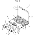
- FIG. 3 is a perspective view of the notebook computer 1 with the housing members B removed.
- insertion openings 18 are formed into which the housing members B may be inserted.
- locking portions 19 for locking the housing members B are provided on the side surface 13 of the housing 10 .
- the housing members B may be completely removed from the housing 10 .
- the housing members B do not necessarily have to be able to be completely removed from the housing 10 as long as the housing members B may be pulled out from the housing 10 .
- the housing members B are an example of a housing member that is housed in the housing 10 so as to be able to be pulled out.
- the insertion openings 18 are an example of an opening into which the housing member B may be inserted.
- FIGS. 4A and 4B are perspective views of one of the housing members B.
- FIG. 5 is a sectional view of the housing member B.
- FIG. 6 is an exploded perspective view of the housing member B.
- FIG. 7 is a partial enlarged view of the housing member B in a state where a locking portion 70 is attached to a lower case 40 .
- the housing member B includes a lower case 40 , an upper case 50 , a lid 60 , and a locking portion 70 .
- the lower case 40 , the upper case 50 , the lid 60 , and the locking portion 70 are made of insulating material, and more specifically, they are made of synthetic resin.
- the lower case 40 and the upper case 50 are assembled together and house batteries BT. All most of parts of the batteries BT are made of metal.
- a recess 48 is formed into which the user's fingers are inserted when the user manually removes the housing member B.
- through-holes 44 and 54 are formed in the lower case 40 and the upper case 50 , respectively. Screw holes are formed in the lid 60 . Screws N inserted into the through-holes 44 and 54 are screwed into the screw holes of the lid 60 .
- the upper case 50 is fixed to the lower case 40
- the lid 60 is fixed to the upper case 50 .
- a protruding engaging portion 49 is formed on the side surface of the front portion of the lower case 40 .
- the engaging portion 49 engages with the locking portion 19 of the housing 10 , and makes it impossible to remove the housing member B from the housing 10 .
- the locking portion 19 is an example of a locking portion that is disengageably engaged with the housing member.
- the locking portion 70 is slidably held between the lower case 40 and the upper case 50 .
- the locking portion 70 includes an extending portion 71 , an operating portion 72 , an engaging portion 73 , and a pin portion 75 .
- the extending portion 71 extends in a predetermined direction.
- the operating portion 72 is provided at one end of the extending portion 71 , and is exposed through a cutout 42 formed in the center of the front of the lower case 40 .
- the engaging portion 73 is a protrusion provided at the other end of the extending portion 71 , and is exposed through a cutout 43 formed in the front portion of the side surface of the lower case 40 .
- the engaging portion 73 of the locking portion 70 engages with the housing 10 when the housing member B is housed in the housing 10 .
- the pin portion 75 extends parallel to the extending portion 71 from the engaging portion 73 .
- the pin portion 75 is inserted into a coil spring S.
- the spring S urges the locking portion 70 attached to the lower case 40 in an urging direction D.
- the locking portion 70 is an example of a locking portion that is disengageably engaged with the first housing. The user slides the locking portion 19 of the housing 10 and thereby releases the lock between the housing 10 and the housing member B. In addition, the user slides the operating portion 72 of the locking portion 70 in a direction opposite to the urging direction D of the spring S and thereby releases the lock between the locking portion 70 and the housing 10 . Thus, the housing member B is removed from the housing 10 .
- the lids 60 of the housing members B housed in the housing 10 are exposed.
- the lids 60 cover the insertion openings 18 of the housing 10 when the housing members B are housed in the housing 10 .
- the side surface 13 of the housing 10 is defined by part of the housing 10 , the cover 30 , and the lids 60 of the housing members B.
- the lid 60 is an example of an exposed portion that is exposed on the surface of the first housing when housed in the first housing and that is made of insulating material.
- FIG. 8A is a perspective view of the notebook computer 1 with the housing 20 disassembled.
- FIG. 8B is a partial enlarged view of FIG. 8A .
- the housing 20 includes a case 20 F disposed at a front side, a case 20 R disposed at a back side, and a cover 20 R 1 .
- the case 20 F defines a front surface 21 .
- the case 20 R and the cover 20 R 1 define a back surface 22 .
- the case 20 F and the cover 20 R 1 are made of insulating material, and more specifically, they are made of synthetic resin.
- the case 20 F and the cover 20 R 1 are an example of a wall portion made of insulating material.
- At least one of the case 20 F and the cover 20 R 1 may be made, for example, of rubber.
- the case 20 R is made of metal.
- the cover 20 R 1 is located above the case 20 R.
- the case 20 F and the cover 20 R 1 define the side surface 23 of the housing 20 .
- Antennas AT 1 to AT 4 and a camera unit CM are disposed inside the cover 20 R 1 .
- FIG. 9 illustrates a state where the antennas AT 1 to AT 4 and the camera unit CM are removed from the case 20 R and the cover 20 R 1 of the housing 20 .
- the antennas AT 1 , AT 2 , and AT 4 have ground portions AT 11 , AT 21 , and AT 41 , respectively, in their lower portions.
- the ground portions AT 11 , AT 21 , and AT 41 are electrically connected to a metal plate fixed to the back surface of the display unit U.
- the antennas AT 1 , AT 2 , and AT 4 have radiation portions AT 13 , AT 23 , and AT 43 , respectively, in their upper portions.
- the radiation portions AT 13 , AT 23 , and AT 43 are not connected to the metal plate to which the ground portions AT 11 , AT 21 , and AT 41 are connected.
- the radiation portions AT 13 , AT 23 , and AT 43 of the antennas AT 1 , AT 2 , and AT 4 , and the antenna AT 3 are surrounded by the case 20 F and the cover 20 R 1 made of synthetic resin.
- the antennas AT 1 to AT 4 are an example of an antenna at least part of which is housed in the second housing and surrounded by the wall portion.
- the receiving sensitivity of the antenna is reduced. Since at least part of each of the antennas AT 1 to AT 4 of this embodiment is surrounded by the case 20 F and the cover 20 R 1 made of synthetic resin, the reduction of the receiving sensitivity of the antennas AT 1 to AT 4 in a deployed state is suppressed.
- a housing formed of a thin metal sheet is strong but lightweight compared to a housing formed of insulating material.
- the case 20 R that is part of the housing 20 is made of metal, and therefore the strength and lightness of the housing 20 are ensured.
- the case 20 F and the cover 20 R 1 that are each part of the housing 20 are made of insulating material, and therefore the reduction of the receiving sensitivity of the antennas AT 1 to AT 4 is suppressed.
- an opening CMO through which the lens of the camera unit CM is exposed is formed in the case 20 F.
- FIG. 10 is a perspective view of the notebook computer 1 in the first superimposed state illustrating the positions of the antennas AT 1 to AT 4 and the camera unit CM.
- FIG. 10 illustrates the antennas AT 1 to AT 4 and the camera unit CM.
- the antennas AT 2 and AT 4 face the lids 60 of the housing members B made of synthetic resin with the case 20 F made of synthetic resin therebetween.
- the antennas AT 2 and AT 4 do not face the batteries BT and the case 10 F made of metal with the case 20 F therebetween.
- the antennas AT 2 and AT 4 face members made of metal with the case 20 F therebetween, the receiving sensitivity of the antennas AT 2 and AT 4 is reduced. However, actually the antennas AT 2 and AT 4 do not face the batteries BT and the case 10 F made of metal. Therefore, also in the first superimposed state, the reduction of the receiving sensitivity of the antennas AT 2 and AT 4 is suppressed. In the first superimposed state, the antenna AT 3 faces the cover 30 . As described above, the cover 30 is made of synthetic resin. Thus, also in the first superimposed state, the reduction of the receiving sensitivity of the antenna AT 3 is suppressed. In this way, the reduction of the receiving sensitivity of the antennas AT 1 to AT 3 is suppressed in the first superimposed state. In the first superimposed state, the opening CMO is covered by the housing 10 , and therefore the camera unit CM may not be used.
- FIG. 11 is a perspective view of the notebook computer 1 in the second superimposed state illustrating the positions of the antennas AT 1 to AT 4 and the camera unit CM.
- FIG. 12 is a sectional view of the notebook computer 1 in the second superimposed state.
- the antennas AT 1 to AT 4 face the housing members B or the cover 30 made of synthetic resin with the case 20 R 1 made of synthetic resin therebetween. Therefore, in the second superimposed state, the reduction of the receiving sensitivity of the antennas AT 1 to AT 4 is suppressed. As described above, the reduction of the receiving sensitivity of the antennas AT 1 to AT 4 is suppressed in any state.
- the opening CMO faces the opposite direction from the housing 10 , and therefore the camera unit CM may be used.
- FIG. 13 is an explanatory view of a housing member Ba that is a first modification.
- the upper case 50 and the lid 60 of the housing member Ba are not illustrated.
- FIG. 14 is a partial enlarged view of the housing member Ba of the first modification in a state where a locking portion 70 a is attached to a lower case 40 a.
- An operating portion 80 a is provided with two guide pins 87 a protruding in the vertical direction.
- a plate-like connecting portion 76 a parallel to the horizontal direction is formed.
- two guide grooves 77 a are formed that are slidably engaged with the guide pins 87 a.
- the guide grooves 77 a extend at an angle to the urging direction D of a spring Sa.
- the user presses the operating portion 80 a in a direction D 1 perpendicular to the urging direction D of the spring Sa, and thereby the guide pins 87 a of the operating portion 80 a move in the guide grooves 77 a.
- the locking portion 70 a moves in a direction opposite to the urging direction D of the spring Sa, and the lock between the housing 10 and the locking portion 70 a is released.
- FIG. 15 is an explanatory view of a housing member Bb that is a second modification.
- FIG. 16 is an exploded perspective view of the housing member Bb that is the second modification.
- An operating portion 80 b has two guide pins 87 b protruding in the horizontal direction and toward the front of the housing member Bb.
- An upper case 50 b has a cutout 52 b formed therein.
- a lid 60 b has a cutout 62 b formed therein.
- the operating portion 80 b is disposed in the cutouts 52 b and 62 b.
- a connecting portion 76 b is formed at one end of an extending portion 71 b of a locking portion 70 b.
- two guide grooves 77 b are formed that are slidably engaged with the guide pins 87 b.
- the guide grooves 77 b extend at an angle to the vertical direction.
- the user presses the operating portion 80 b in a vertically downward direction D 2 perpendicular to the urging direction D of a spring Sb, and thereby the guide pins 87 b of the operating portion 80 b move in the guide grooves 77 b.
- the locking portion 70 b moves in a direction opposite to the urging direction D of the spring Sb, and the lock between the housing 10 and the locking portion 70 b is released.
- a notebook computer has been described as an example of a portable device.
- the present invention may be applied to any other portable device, for example, a cellular phone, a portable television, an electronic dictionary, a PDA, a game machine, a camera, a music player, or a navigation device.
- a housing member B holding batteries BT has been described as an example of a housing member.
- a housing member B is not limited to this.
- a housing member B may be a tray that may hold at least one of a flash memory, a hard disk, and a storage medium.
- At least one of the antennas AT 1 to AT 4 may face both the lid 60 of the housing member B and the cover 30 with the case 20 F therebetween in the first superimposed state.
Landscapes
- Engineering & Computer Science (AREA)
- Computer Hardware Design (AREA)
- Theoretical Computer Science (AREA)
- General Engineering & Computer Science (AREA)
- Physics & Mathematics (AREA)
- Human Computer Interaction (AREA)
- General Physics & Mathematics (AREA)
- Power Engineering (AREA)
- Mathematical Physics (AREA)
- Casings For Electric Apparatus (AREA)
- Support Of Aerials (AREA)
- Telephone Set Structure (AREA)
Abstract
Description
- This application is based upon and claims the benefit of priority of the prior Japanese Patent Application No. 2011-076337, filed on Mar. 30, 2011, the entire contents of which are incorporated herein by reference.
- The embodiments discussed herein are related to a portable device.
- A portable device is known that has a first housing, and a second housing connected to the first housing so as to be able to be superimposed on the first housing (Japanese Laid-open Patent Publication No. 2002-232220, Japanese Registered Utility Model No. 3027116, and Japanese Laid-open Patent Publication No. 2000-17466). Some of the portable devices include an antenna in the second housing. In these portable devices, the wall portion of the second housing surrounding the antenna is formed of insulating material in order to suppress influence on the transmitting and receiving of radio waves by the antenna.
- In the superimposed state, the antenna housed in the second housing faces the first housing with the wall portion of the second housing therebetween. Therefore, depending on the material of the first housing, the first housing may exert influence on the receiving sensitivity of the antenna in the superimposed state.
- According to an aspect of the invention, a portable device includes a first housing, a housing member removable from the first housing, the housing member including an exposed portion, the exposed portion projecting from the first housing when the housing member is inserted in the first housing, a second housing coupled with the first housing so as to be allowed to be folded on the first housing, the second housing including a wall made of electrical insulating material, and an antenna disposed in the second housing and surrounded partially with the wall, a part of the antenna and the exposed portion facing each other via the wall when the first and second housings are folded on each other.
- The object and advantages of the invention will be realized and attained by means of the elements and combinations particularly pointed out in the claims.
- It is to be understood that both the foregoing general description and the following detailed description are exemplary and explanatory and are not restrictive of the invention, as claimed.
- The present invention may provide a portable device in which the reduction of the receiving sensitivity of an antenna is suppressed in a state where first and second housings are superimposed on each other.
-
FIGS. 1A to 1C are explanatory views of a notebook computer of this embodiment. -
FIG. 2 is an exploded perspective view of a housing. -
FIG. 3 is a perspective view of the notebook computer with housing members removed. -
FIGS. 4A and 4B are perspective views of one of the housing members. -
FIG. 5 is a sectional view of the housing member. -
FIG. 6 is an exploded perspective view of the housing member. -
FIG. 7 is a partial enlarged view of the housing member in a state where a locking portion is attached to a lower case. -
FIG. 8A is a perspective view of the notebook computer with a housing disassembled.FIG. 8B is a partial enlarged view ofFIG. 8A . -
FIG. 9 illustrates a state where antennas and a camera unit are removed from a case and a cover of the housing. -
FIG. 10 is a perspective view of the notebook computer in a first superimposed state illustrating the positions of the antennas and the camera unit. -
FIG. 11 is a perspective view of the notebook computer in a second superimposed state illustrating the positions of the antennas and the camera unit. -
FIG. 12 is a sectional view of the notebook computer in the second superimposed state. -
FIG. 13 is an explanatory view of a housing member that is a first modification. -
FIG. 14 is a partial enlarged view of the housing member of the first modification in a state where a locking portion is attached to a lower case. -
FIG. 15 is an explanatory view of a housing member that is a second modification. -
FIG. 16 is an exploded perspective view of the housing member that is the second modification. - A notebook computer will be described as an example of a portable device.
FIGS. 1A to 1C are explanatory views of anotebook computer 1 of this embodiment. Thenotebook computer 1 hashousings housing 10 is an example of a first housing. Thehousing 20 is an example of a second housing. Thehousings housing 10 has anupper surface 11, a bottom surface facing theupper surface 11, andside surfaces upper surface 11 and the bottom surface. Theside surfaces upper surface 11 and the bottom surface. Theupper surface 11 of thehousing 10 is an example of a third surface. The bottom surface of thehousing 10 is an example of a fourth surface. Theside surface 13 is an example of a fifth surface. Theupper surface 11 is provided with a keyboard K for operating thenotebook computer 1, and acover 30. Theside surface 15 is provided with a plurality of ports and connectors. Thehousing 10 houses a mother board for controlling the overall operation of thenotebook computer 1. Thehousing 10 houses two detachable housing members B. The two housing members B are provided on either side of thecover 30. - The
housing 20 has afront surface 21, aback surface 22 facing thefront surface 21, andside surfaces front surface 21 and theback surface 22. Theside surfaces front surface 21 and theback surface 22. Thefront surface 21 of thehousing 20 is an example of a first surface. Theback surface 22 of thehousing 20 is an example of a second surface. Thefront surface 21 is provided with a display unit U. The display unit U includes a display panel that may display images, and a touch panel that may be operated by touching. Various types of touch panels, such as a resistive touch panel, a surface acoustic wave touch panel, and an infrared touch panel, may be used as the touch panel. An electrostatic capacitance touch panel may also be used that does not require a stylus pen and that uses the change in the electrostatic capacitance between the user's finger and a conductive film. Instead of the touch panel, an electromagnetic induction pen tablet that is operated with a stylus pen may be used. - The biaxial hinge H connects the
housings upper surface 11 extends. The axis A2 extends in a direction that intersects theupper surface 11. That is to say, the axes A1 and A2 intersect. -
FIG. 1A illustrates a first superimposed state where thefront surface 21 of thehousing 20 is superimposed on theupper surface 11 of thehousing 10.FIG. 1B illustrates an open state where thehousings FIG. 1C illustrates a second superimposed state where theback surface 22 of thehousing 20 is superimposed on theupper surface 11 of thehousing 10. From the first superimposed state, the user rotates thehousing 20 about the axis A1, thereby bringing thenotebook computer 1 into the open state. From the open state ofFIG. 1B , the user rotates thehousing 20 about the axis A2 such that theback surface 22 of thehousing 20 and theupper surface 11 of thehousing 10 face each other. The user may rotate thehousing 20 about the axis A1 such that thehousing 20 is superimposed on thehousing 10 with theback surface 22 of thehousing 20 and theupper surface 11 of thehousing 10 facing each other. Thus, thenotebook computer 1 is brought into the second superimposed state where theupper surface 11 of thehousing 10 and theback surface 22 of thehousing 20 face each other. -
FIG. 2 is an exploded perspective view of thehousing 10. Thehousing 10 includescases cover 30. Thecases cover 30 is made of insulating material, and more specifically, it is made of synthetic resin. However, the material of thecover 30 is not limited to this. Thecover 30 may be made, for example, of rubber. Thecover 30 covers an electrostatic capacitance touch sensor SN. When the user's finger touches thecover 30, the touch sensor SN disposed inside thecover 30 detects the position of the user's finger. Thecover 30 is attached to thecase 10F. Theupper surface 11 of thehousing 10 is defined by thecase 10F and thecover 30. Thebottom surface 12 of thehousing 10 is defined by thecase 10R. - On the
case 10R side, there are disposed a mother board M, a heat pipe HP that receives heat from a semiconductor chip CP mounted on the mother board M, a radiator R connected to the heat pipe HP, and a fan F that cools the radiator R. Thecase 10R houses a stylus pen P for operating the touch panel of the display unit U. In thecase 10R, two housing members B are disposed. The two housing members B are housed in thehousing 10 and are disposed on either side of thecover 30. - Most of the
housing 10 is defined by themetal cases housing 10 is formed of metal, and therefore the strength and lightness of thehousing 10 are ensured. -
FIG. 3 is a perspective view of thenotebook computer 1 with the housing members B removed. In theside surface 13 of thehousing 10,insertion openings 18 are formed into which the housing members B may be inserted. On theside surface 13 of thehousing 10, lockingportions 19 for locking the housing members B are provided. By sliding the lockingportions 19 in the longitudinal direction of theside surface 13 of thehousing 10, the lock on the housing members B housed in thehousing 10 is released. The housing members B may be completely removed from thehousing 10. However, the housing members B do not necessarily have to be able to be completely removed from thehousing 10 as long as the housing members B may be pulled out from thehousing 10. The housing members B are an example of a housing member that is housed in thehousing 10 so as to be able to be pulled out. Theinsertion openings 18 are an example of an opening into which the housing member B may be inserted. - The housing members B will be described.
FIGS. 4A and 4B are perspective views of one of the housing members B.FIG. 5 is a sectional view of the housing member B.FIG. 6 is an exploded perspective view of the housing member B.FIG. 7 is a partial enlarged view of the housing member B in a state where a lockingportion 70 is attached to alower case 40. The housing member B includes alower case 40, anupper case 50, alid 60, and a lockingportion 70. Thelower case 40, theupper case 50, thelid 60, and the lockingportion 70 are made of insulating material, and more specifically, they are made of synthetic resin. Thelower case 40 and theupper case 50 are assembled together and house batteries BT. All most of parts of the batteries BT are made of metal. As illustrated inFIG. 5 , in the front of thelower case 40, arecess 48 is formed into which the user's fingers are inserted when the user manually removes the housing member B. - As illustrated in
FIG. 6 , through-holes lower case 40 and theupper case 50, respectively. Screw holes are formed in thelid 60. Screws N inserted into the through-holes lid 60. Thus, theupper case 50 is fixed to thelower case 40, and thelid 60 is fixed to theupper case 50. - As illustrated in
FIGS. 6 and 7 , a protruding engagingportion 49 is formed on the side surface of the front portion of thelower case 40. When the housing member B is housed in thehousing 10, the engagingportion 49 engages with the lockingportion 19 of thehousing 10, and makes it impossible to remove the housing member B from thehousing 10. The lockingportion 19 is an example of a locking portion that is disengageably engaged with the housing member. - As illustrated in
FIGS. 6 and 7 , the lockingportion 70 is slidably held between thelower case 40 and theupper case 50. The lockingportion 70 includes an extendingportion 71, an operatingportion 72, an engagingportion 73, and apin portion 75. The extendingportion 71 extends in a predetermined direction. The operatingportion 72 is provided at one end of the extendingportion 71, and is exposed through acutout 42 formed in the center of the front of thelower case 40. The engagingportion 73 is a protrusion provided at the other end of the extendingportion 71, and is exposed through acutout 43 formed in the front portion of the side surface of thelower case 40. The engagingportion 73 of the lockingportion 70 engages with thehousing 10 when the housing member B is housed in thehousing 10. Thepin portion 75 extends parallel to the extendingportion 71 from the engagingportion 73. Thepin portion 75 is inserted into a coil spring S. - As illustrated in
FIG. 7 , the spring S urges the lockingportion 70 attached to thelower case 40 in an urging direction D. Thus, when the housing member B is housed in thehousing 10, the engagement between the engagingportion 73 of the lockingportion 70 and thehousing 10 is maintained, and it becomes impossible to remove the housing member B. The lockingportion 70 is an example of a locking portion that is disengageably engaged with the first housing. The user slides the lockingportion 19 of thehousing 10 and thereby releases the lock between thehousing 10 and the housing member B. In addition, the user slides the operatingportion 72 of the lockingportion 70 in a direction opposite to the urging direction D of the spring S and thereby releases the lock between the lockingportion 70 and thehousing 10. Thus, the housing member B is removed from thehousing 10. - As illustrated in
FIGS. 1A to 1C andFIG. 2 , thelids 60 of the housing members B housed in thehousing 10 are exposed. In other words, thelids 60 cover theinsertion openings 18 of thehousing 10 when the housing members B are housed in thehousing 10. Theside surface 13 of thehousing 10 is defined by part of thehousing 10, thecover 30, and thelids 60 of the housing members B. Thelid 60 is an example of an exposed portion that is exposed on the surface of the first housing when housed in the first housing and that is made of insulating material. - Next, antennas housed in the
housing 20 will be described.FIG. 8A is a perspective view of thenotebook computer 1 with thehousing 20 disassembled.FIG. 8B is a partial enlarged view ofFIG. 8A . Thehousing 20 includes acase 20F disposed at a front side, acase 20R disposed at a back side, and a cover 20R1. Thecase 20F defines afront surface 21. Thecase 20R and the cover 20R1 define aback surface 22. Thecase 20F and the cover 20R1 are made of insulating material, and more specifically, they are made of synthetic resin. Thecase 20F and the cover 20R1 are an example of a wall portion made of insulating material. At least one of thecase 20F and the cover 20R1 may be made, for example, of rubber. Thecase 20R is made of metal. The cover 20R1 is located above thecase 20R. Thecase 20F and the cover 20R1 define theside surface 23 of thehousing 20. Antennas AT1 to AT4 and a camera unit CM are disposed inside the cover 20R1. -
FIG. 9 illustrates a state where the antennas AT1 to AT4 and the camera unit CM are removed from thecase 20R and the cover 20R1 of thehousing 20. The antennas AT1, AT2, and AT4 have ground portions AT11, AT21, and AT41, respectively, in their lower portions. The ground portions AT11, AT21, and AT41 are electrically connected to a metal plate fixed to the back surface of the display unit U. The antennas AT1, AT2, and AT4 have radiation portions AT13, AT23, and AT43, respectively, in their upper portions. The radiation portions AT13, AT23, and AT43 are not connected to the metal plate to which the ground portions AT11, AT21, and AT41 are connected. As illustrated inFIG. 8B , the radiation portions AT13, AT23, and AT43 of the antennas AT1, AT2, and AT4, and the antenna AT3 are surrounded by thecase 20F and the cover 20R1 made of synthetic resin. - Therefore, the antennas AT1 to AT4 are an example of an antenna at least part of which is housed in the second housing and surrounded by the wall portion. In general, if a member made of metal is near an antenna, the receiving sensitivity of the antenna is reduced. Since at least part of each of the antennas AT1 to AT4 of this embodiment is surrounded by the
case 20F and the cover 20R1 made of synthetic resin, the reduction of the receiving sensitivity of the antennas AT1 to AT4 in a deployed state is suppressed. - As described above, metals are denser than insulating materials, and metals are stronger than insulating materials. Therefore, a housing formed of a thin metal sheet is strong but lightweight compared to a housing formed of insulating material. In this embodiment, the
case 20R that is part of thehousing 20 is made of metal, and therefore the strength and lightness of thehousing 20 are ensured. In addition, thecase 20F and the cover 20R1 that are each part of thehousing 20 are made of insulating material, and therefore the reduction of the receiving sensitivity of the antennas AT1 to AT4 is suppressed. As illustrated inFIG. 8A , an opening CMO through which the lens of the camera unit CM is exposed is formed in thecase 20F. -
FIG. 10 is a perspective view of thenotebook computer 1 in the first superimposed state illustrating the positions of the antennas AT1 to AT4 and the camera unit CM.FIG. 10 illustrates the antennas AT1 to AT4 and the camera unit CM. In the first superimposed state, the antennas AT2 and AT4 face thelids 60 of the housing members B made of synthetic resin with thecase 20F made of synthetic resin therebetween. In other words, in the first superimposed state, the antennas AT2 and AT4 do not face the batteries BT and thecase 10F made of metal with thecase 20F therebetween. - If the antennas AT2 and AT4 face members made of metal with the
case 20F therebetween, the receiving sensitivity of the antennas AT2 and AT4 is reduced. However, actually the antennas AT2 and AT4 do not face the batteries BT and thecase 10F made of metal. Therefore, also in the first superimposed state, the reduction of the receiving sensitivity of the antennas AT2 and AT4 is suppressed. In the first superimposed state, the antenna AT3 faces thecover 30. As described above, thecover 30 is made of synthetic resin. Thus, also in the first superimposed state, the reduction of the receiving sensitivity of the antenna AT3 is suppressed. In this way, the reduction of the receiving sensitivity of the antennas AT1 to AT3 is suppressed in the first superimposed state. In the first superimposed state, the opening CMO is covered by thehousing 10, and therefore the camera unit CM may not be used. -
FIG. 11 is a perspective view of thenotebook computer 1 in the second superimposed state illustrating the positions of the antennas AT1 to AT4 and the camera unit CM.FIG. 12 is a sectional view of thenotebook computer 1 in the second superimposed state. Also in the second superimposed state, the antennas AT1 to AT4 face the housing members B or thecover 30 made of synthetic resin with the case 20R1 made of synthetic resin therebetween. Therefore, in the second superimposed state, the reduction of the receiving sensitivity of the antennas AT1 to AT4 is suppressed. As described above, the reduction of the receiving sensitivity of the antennas AT1 to AT4 is suppressed in any state. In the second superimposed state, the opening CMO faces the opposite direction from thehousing 10, and therefore the camera unit CM may be used. -
FIG. 13 is an explanatory view of a housing member Ba that is a first modification. Theupper case 50 and thelid 60 of the housing member Ba are not illustrated.FIG. 14 is a partial enlarged view of the housing member Ba of the first modification in a state where a lockingportion 70 a is attached to alower case 40 a. An operatingportion 80 a is provided with two guide pins 87 a protruding in the vertical direction. At one end of an extendingportion 71 a of the lockingportion 70 a, a plate-like connectingportion 76 a parallel to the horizontal direction is formed. In the connectingportion 76 a, twoguide grooves 77 a are formed that are slidably engaged with the guide pins 87 a. Theguide grooves 77 a extend at an angle to the urging direction D of a spring Sa. The user presses the operatingportion 80 a in a direction D1 perpendicular to the urging direction D of the spring Sa, and thereby the guide pins 87 a of the operatingportion 80 a move in theguide grooves 77 a. Thus, the lockingportion 70 a moves in a direction opposite to the urging direction D of the spring Sa, and the lock between thehousing 10 and the lockingportion 70 a is released. -
FIG. 15 is an explanatory view of a housing member Bb that is a second modification.FIG. 16 is an exploded perspective view of the housing member Bb that is the second modification. An operatingportion 80 b has two guide pins 87 b protruding in the horizontal direction and toward the front of the housing member Bb. Anupper case 50 b has acutout 52 b formed therein. Alid 60 b has acutout 62 b formed therein. The operatingportion 80 b is disposed in thecutouts portion 71 b of a lockingportion 70 b, a connectingportion 76 b is formed. In the connectingportion 76 b, twoguide grooves 77 b are formed that are slidably engaged with the guide pins 87 b. Theguide grooves 77 b extend at an angle to the vertical direction. The user presses the operatingportion 80 b in a vertically downward direction D2 perpendicular to the urging direction D of a spring Sb, and thereby the guide pins 87 b of the operatingportion 80 b move in theguide grooves 77 b. Thus, the lockingportion 70 b moves in a direction opposite to the urging direction D of the spring Sb, and the lock between thehousing 10 and the lockingportion 70 b is released. - Although a preferred embodiment of the present invention has been described, it is to be understood that the present invention is not intended to be limited to the above-described specific embodiment, and various changes may be made without departing from the scope of the present invention set forth in the appended claims.
- In the above embodiment, a notebook computer has been described as an example of a portable device. However, the present invention may be applied to any other portable device, for example, a cellular phone, a portable television, an electronic dictionary, a PDA, a game machine, a camera, a music player, or a navigation device.
- In the above embodiment, a housing member B holding batteries BT has been described as an example of a housing member. However, a housing member B is not limited to this. For example, a housing member B may be a tray that may hold at least one of a flash memory, a hard disk, and a storage medium.
- In the above embodiment, at least one of the antennas AT1 to AT4 may face both the
lid 60 of the housing member B and thecover 30 with thecase 20F therebetween in the first superimposed state. - All examples and conditional language recited herein are intended for pedagogical purposes to aid the reader in understanding the invention and the concepts contributed by the inventor to furthering the art, and are to be construed as being without limitation to such specifically recited examples and conditions, nor does the organization of such examples in the specification relate to a showing of the superiority and inferiority of the invention. Although the embodiments of the present inventions have been described in detail, it should be understood that the various changes, substitutions, and alterations could be made hereto without departing from the spirit and scope of the invention.
Claims (7)
Applications Claiming Priority (2)
| Application Number | Priority Date | Filing Date | Title |
|---|---|---|---|
| JP2011076337A JP2012212971A (en) | 2011-03-30 | 2011-03-30 | Portable device |
| JP2011-076337 | 2011-03-30 |
Publications (2)
| Publication Number | Publication Date |
|---|---|
| US20120249379A1 true US20120249379A1 (en) | 2012-10-04 |
| US8803746B2 US8803746B2 (en) | 2014-08-12 |
Family
ID=46021982
Family Applications (1)
| Application Number | Title | Priority Date | Filing Date |
|---|---|---|---|
| US13/426,798 Expired - Fee Related US8803746B2 (en) | 2011-03-30 | 2012-03-22 | Portable device with a first and second housing with an electrically insulated antenna |
Country Status (3)
| Country | Link |
|---|---|
| US (1) | US8803746B2 (en) |
| EP (1) | EP2506111A3 (en) |
| JP (1) | JP2012212971A (en) |
Cited By (1)
| Publication number | Priority date | Publication date | Assignee | Title |
|---|---|---|---|---|
| US20200192438A1 (en) * | 2018-12-14 | 2020-06-18 | Dell Products L.P. | Information handling system antenna isolation with integrated cooling fan |
Families Citing this family (1)
| Publication number | Priority date | Publication date | Assignee | Title |
|---|---|---|---|---|
| US10162383B2 (en) * | 2017-03-21 | 2018-12-25 | Google Llc | Electronic device with brace for edge-to-edge opening |
Citations (4)
| Publication number | Priority date | Publication date | Assignee | Title |
|---|---|---|---|---|
| US7366304B2 (en) * | 2003-10-07 | 2008-04-29 | Lenovo (Singapore) Pte. Ltd. | Cruable U-NII wireless radio with secure, integral antenna connection via SM BIOS in U-NII wireless ready device |
| US7509143B2 (en) * | 2000-07-18 | 2009-03-24 | Option | Telecommunications card with integrated antenna |
| US7852319B2 (en) * | 2006-04-26 | 2010-12-14 | Kabushiki Kaisha Toshiba | Information processing apparatus and operation control method |
| US7916463B2 (en) * | 2008-09-12 | 2011-03-29 | Kabushiki Kaisha Toshiba | Information processing apparatus |
Family Cites Families (8)
| Publication number | Priority date | Publication date | Assignee | Title |
|---|---|---|---|---|
| JPH0327116A (en) | 1989-06-21 | 1991-02-05 | Toray Ind Inc | Production of polyamide monofilament |
| JP3027116U (en) * | 1996-01-23 | 1996-07-30 | 廣達電脳股▲分▼有限公司 | Portable computer housing structure |
| US5822547A (en) * | 1996-05-31 | 1998-10-13 | Texas Instruments Incorporated | Method and apparatus for providing a portable computer with hot pluggable modular bays |
| JP2000174466A (en) | 1998-12-07 | 2000-06-23 | Nec Corp | External device storage bay |
| JP4157280B2 (en) * | 2001-02-05 | 2008-10-01 | 株式会社東芝 | Electronics |
| WO2004066131A1 (en) * | 2003-01-17 | 2004-08-05 | Fujitsu Limited | Information processor |
| JP2004264930A (en) * | 2003-02-28 | 2004-09-24 | Toshiba Corp | Support member and electronic device |
| WO2010005423A1 (en) * | 2008-07-07 | 2010-01-14 | Hewlett-Packard Development Company, L.P. | Tablet computers having an internal antenna |
-
2011
- 2011-03-30 JP JP2011076337A patent/JP2012212971A/en active Pending
-
2012
- 2012-03-22 US US13/426,798 patent/US8803746B2/en not_active Expired - Fee Related
- 2012-03-22 EP EP12160724.6A patent/EP2506111A3/en not_active Withdrawn
Patent Citations (4)
| Publication number | Priority date | Publication date | Assignee | Title |
|---|---|---|---|---|
| US7509143B2 (en) * | 2000-07-18 | 2009-03-24 | Option | Telecommunications card with integrated antenna |
| US7366304B2 (en) * | 2003-10-07 | 2008-04-29 | Lenovo (Singapore) Pte. Ltd. | Cruable U-NII wireless radio with secure, integral antenna connection via SM BIOS in U-NII wireless ready device |
| US7852319B2 (en) * | 2006-04-26 | 2010-12-14 | Kabushiki Kaisha Toshiba | Information processing apparatus and operation control method |
| US7916463B2 (en) * | 2008-09-12 | 2011-03-29 | Kabushiki Kaisha Toshiba | Information processing apparatus |
Cited By (4)
| Publication number | Priority date | Publication date | Assignee | Title |
|---|---|---|---|---|
| US20200192438A1 (en) * | 2018-12-14 | 2020-06-18 | Dell Products L.P. | Information handling system antenna isolation with integrated cooling fan |
| US10852782B2 (en) * | 2018-12-14 | 2020-12-01 | Dell Products L.P. | Information handling system antenna isolation with integrated cooling fan |
| US11513568B2 (en) | 2018-12-14 | 2022-11-29 | Dell Products L.P. | Information handling system antenna isolation with integrated cooling fan |
| US11983049B2 (en) | 2018-12-14 | 2024-05-14 | Dell Products L.P. | Information handling system antenna isolation with integrated cooling fan |
Also Published As
| Publication number | Publication date |
|---|---|
| EP2506111A3 (en) | 2015-06-10 |
| JP2012212971A (en) | 2012-11-01 |
| US8803746B2 (en) | 2014-08-12 |
| EP2506111A2 (en) | 2012-10-03 |
Similar Documents
| Publication | Publication Date | Title |
|---|---|---|
| US11927990B2 (en) | Computing device | |
| US8369097B2 (en) | Electronic apparatus | |
| US9274557B2 (en) | Stand for electronic device and electronic device | |
| US9192061B2 (en) | Electronic device | |
| EP3391175B1 (en) | Electronic device with cradling function | |
| US20140340829A1 (en) | Electronic device | |
| US20140355210A1 (en) | Stand for electronic device and electronic device | |
| US9575513B2 (en) | Electronic device and apparatus | |
| US20100297485A1 (en) | Battery cover | |
| US11914426B2 (en) | Computing device | |
| US10043114B2 (en) | Electronic device | |
| US8803746B2 (en) | Portable device with a first and second housing with an electrically insulated antenna | |
| US7486501B2 (en) | Information processing device | |
| US20070047197A1 (en) | Electronic apparatus | |
| US12019472B2 (en) | Computing device | |
| JP5286975B2 (en) | Electronics | |
| US20070047191A1 (en) | Electronic apparatus | |
| US8787026B2 (en) | Electronic apparatus | |
| US9244336B2 (en) | Battery cover assembly with sliding door, and portable electronic device including the battery cover assembly | |
| US20180059723A1 (en) | Electronic device | |
| US20060210866A1 (en) | Electronic apparatus | |
| US20160062416A1 (en) | Hinge apparatus and electronic device | |
| US8289704B2 (en) | Electronic apparatus | |
| US7283356B2 (en) | Electronic apparatus | |
| US9681547B2 (en) | Electronic device |
Legal Events
| Date | Code | Title | Description |
|---|---|---|---|
| AS | Assignment |
Owner name: FUJITSU LIMITED, JAPAN Free format text: ASSIGNMENT OF ASSIGNORS INTEREST;ASSIGNORS:MATSUSHITA, SHINYA;MIHARA, DAISUKE;ABE, TAKASHI;REEL/FRAME:027912/0147 Effective date: 20120306 |
|
| FEPP | Fee payment procedure |
Free format text: MAINTENANCE FEE REMINDER MAILED (ORIGINAL EVENT CODE: REM.) |
|
| LAPS | Lapse for failure to pay maintenance fees |
Free format text: PATENT EXPIRED FOR FAILURE TO PAY MAINTENANCE FEES (ORIGINAL EVENT CODE: EXP.); ENTITY STATUS OF PATENT OWNER: LARGE ENTITY |
|
| STCH | Information on status: patent discontinuation |
Free format text: PATENT EXPIRED DUE TO NONPAYMENT OF MAINTENANCE FEES UNDER 37 CFR 1.362 |
|
| FP | Lapsed due to failure to pay maintenance fee |
Effective date: 20180812 |