US20120249357A1 - Antenna/optics system and method - Google Patents
Antenna/optics system and method Download PDFInfo
- Publication number
- US20120249357A1 US20120249357A1 US13/076,836 US201113076836A US2012249357A1 US 20120249357 A1 US20120249357 A1 US 20120249357A1 US 201113076836 A US201113076836 A US 201113076836A US 2012249357 A1 US2012249357 A1 US 2012249357A1
- Authority
- US
- United States
- Prior art keywords
- radome
- missile
- wedge
- radar system
- signals
- Prior art date
- Legal status (The legal status is an assumption and is not a legal conclusion. Google has not performed a legal analysis and makes no representation as to the accuracy of the status listed.)
- Granted
Links
Images


Classifications
-
- H—ELECTRICITY
- H01—ELECTRIC ELEMENTS
- H01Q—ANTENNAS, i.e. RADIO AERIALS
- H01Q1/00—Details of, or arrangements associated with, antennas
- H01Q1/27—Adaptation for use in or on movable bodies
- H01Q1/28—Adaptation for use in or on aircraft, missiles, satellites, or balloons
- H01Q1/281—Nose antennas
-
- F—MECHANICAL ENGINEERING; LIGHTING; HEATING; WEAPONS; BLASTING
- F41—WEAPONS
- F41G—WEAPON SIGHTS; AIMING
- F41G3/00—Aiming or laying means
- F41G3/14—Indirect aiming means
- F41G3/145—Indirect aiming means using a target illuminator
-
- F—MECHANICAL ENGINEERING; LIGHTING; HEATING; WEAPONS; BLASTING
- F41—WEAPONS
- F41G—WEAPON SIGHTS; AIMING
- F41G7/00—Direction control systems for self-propelled missiles
- F41G7/008—Combinations of different guidance systems
-
- F—MECHANICAL ENGINEERING; LIGHTING; HEATING; WEAPONS; BLASTING
- F41—WEAPONS
- F41G—WEAPON SIGHTS; AIMING
- F41G7/00—Direction control systems for self-propelled missiles
- F41G7/20—Direction control systems for self-propelled missiles based on continuous observation of target position
- F41G7/22—Homing guidance systems
- F41G7/2246—Active homing systems, i.e. comprising both a transmitter and a receiver
-
- F—MECHANICAL ENGINEERING; LIGHTING; HEATING; WEAPONS; BLASTING
- F41—WEAPONS
- F41G—WEAPON SIGHTS; AIMING
- F41G7/00—Direction control systems for self-propelled missiles
- F41G7/20—Direction control systems for self-propelled missiles based on continuous observation of target position
- F41G7/22—Homing guidance systems
- F41G7/226—Semi-active homing systems, i.e. comprising a receiver and involving auxiliary illuminating means, e.g. using auxiliary guiding missiles
-
- F—MECHANICAL ENGINEERING; LIGHTING; HEATING; WEAPONS; BLASTING
- F41—WEAPONS
- F41G—WEAPON SIGHTS; AIMING
- F41G7/00—Direction control systems for self-propelled missiles
- F41G7/20—Direction control systems for self-propelled missiles based on continuous observation of target position
- F41G7/22—Homing guidance systems
- F41G7/2273—Homing guidance systems characterised by the type of waves
- F41G7/2286—Homing guidance systems characterised by the type of waves using radio waves
-
- F—MECHANICAL ENGINEERING; LIGHTING; HEATING; WEAPONS; BLASTING
- F41—WEAPONS
- F41G—WEAPON SIGHTS; AIMING
- F41G7/00—Direction control systems for self-propelled missiles
- F41G7/20—Direction control systems for self-propelled missiles based on continuous observation of target position
- F41G7/22—Homing guidance systems
- F41G7/2273—Homing guidance systems characterised by the type of waves
- F41G7/2293—Homing guidance systems characterised by the type of waves using electromagnetic waves other than radio waves
-
- H—ELECTRICITY
- H01—ELECTRIC ELEMENTS
- H01Q—ANTENNAS, i.e. RADIO AERIALS
- H01Q1/00—Details of, or arrangements associated with, antennas
- H01Q1/42—Housings not intimately mechanically associated with radiating elements, e.g. radome
-
- H—ELECTRICITY
- H01—ELECTRIC ELEMENTS
- H01Q—ANTENNAS, i.e. RADIO AERIALS
- H01Q1/00—Details of, or arrangements associated with, antennas
- H01Q1/42—Housings not intimately mechanically associated with radiating elements, e.g. radome
- H01Q1/422—Housings not intimately mechanically associated with radiating elements, e.g. radome comprising two or more layers of dielectric material
Definitions
- the present invention relates to radar systems and methods, such as missile radar systems and methods.
- Radomes are structures designed to cover antennas and thereby to protect them from direct exposure to aerodynamic and environmental conditions, while being as transparent as possible to the antenna's electromagnetic (EM) radiation.
- EM electromagnetic
- many types of radomes include various forms of discontinuities or blockages. These discontinuities are not necessarily due to material changes, but in many cases due to shape changes.
- radomes on high-speed, airborne platforms are usually equipped with a metallic tip to protect the radome against rain, erosion, etc.
- the metallic tip is at the very end of a dielectric/lossy edge which is an extension of the radome body, which is also lossy since it is the same material as the radome body.
- Surfaces inside the radome (cylindrical portion) that are at a certain distance from the main wedge have some blockage of the outgoing RF energy, but the blockage is not significant. Going further forward on the radome, in the region where the wedge begins to form, that part of the wedge acts almost as a metallic entity, especially at higher frequencies. This is because of the lossy material, combined with the wedge (i.e., the shape change), causes a significant blockage of the RF energy transmitted by the main antenna.
- That RF energy blockage causes a hole in the radiation pattern for the antenna, which is a bad thing since certain areas that are supposed to be covered by the RF energy, are in reality not covered.
- This lossy wedge compared to the rest of the radome body which is cylindrical, causes a significant RF blockage, for the incoming or out coming RF energy.
- This lossy wedge has been found to lead to EM discontinuities for the main antenna located in the back of the radome.
- An approach to ameliorating these discontinuities is to add a lossless wedge just before the metallic tip and go backwards between the radome tip and the antenna.
- This lossless wedge could be transparent glass or non transparent glass.
- the use of a lossless transparent material also provides the opportunity to introduce optics capabilities in addition to the removal of the radiation pattern hole.
- a missile includes different radiatively-transmissive materials in its radome body and its radome tip.
- a radome has an optically-transmissive tip.
- a radome has a tip that is substantially optically transparent.
- a missile emits encoded laser signals through its radome.
- a missile radar system includes: a main antenna; and a radome enclosing the main antenna.
- the radome includes a radome body and a radome wedge.
- the radome body has a wide end and a narrow end, with the main antenna at the wide end, and the radome wedge at the narrow end.
- the radome wedge and the radome body include different materials that are substantially transparent to radar signals emitted by the main antenna.
- a method of missile target guidance includes the steps of: receiving a reflected signal from an intended target of a missile, wherein the reflected signal is received at a seeker of a missile, after passing through an optically-transparent radome wedge of the missile; examining the reflected signal for the presence of signals not including encoding associated with the missile; and if the reflected signal includes signals including encoding not associated with the missile, rejecting and not using for navigation purposes the signals including encoding not associated with the missile.
- a method of improving performance of an antenna includes the steps of: providing a radome with a lossless, optically transparent radome wedge and a lossy dielectric radome body; and placing the antenna within the radome.
- a missile optical system includes: a radome having an optically transmissive front radome wedge; a seeker that within the radome that sends and receives optical signals on an optical path that passes through the optically transmissive front radome wedge; and one or more lenses in the optical path, between the seeker and the optically transmissive front radome wedge.
- FIG. 1 is a cross-sectional view of a missile including a missile radar system in accordance with an embodiment of the present invention.
- FIG. 2 is a cross-section view of part of the missile radar system of FIG. 1 , showing further details near the tip of the missile.
- FIG. 3 is a schematic diagram illustrating employment of the missile radar system of FIG. 1 in a situation where two missiles are targeting separate targets.
- FIG. 4 is a diagram illustrating the free space signal strength of signals received by an antenna such as the main antenna of the missile radar system of FIG. 1 , in the absence of a radome.
- FIG. 5 is a diagram illustrating the free space signal strength of signals received by an antenna such as the main antenna of the missile radar system of FIG. 1 , in the presence of a prior art radome having a lossy non transparent wedge (or edge).
- FIG. 6 is a diagram illustrating the signal strength in the presence of a prior art radome having a lossy non transparent wedge (or edge).
- FIG. 7 is another diagram illustrating the signal strength in the presence of a prior art radome having a lossy non transparent wedge (or edge).
- FIG. 8 is a plot illustrating radar strength in an example RF coverage area scanned by a radar system utilizing a prior art radome having a lossy non transparent wedge (or edge).
- FIG. 9 is a diagram illustrating the signal strength in the presence of a radome according to an embodiment of the present invention indicating the improvement of the angle of arrival.
- FIG. 10 is a plot illustrating radar strength in an example of RF coverage area (system level) scanned by a radar system utilizing a radome according to an embodiment of the present invention.
- a missile includes a radar system that has a radome through which a main antenna sends and receives signals.
- the radome includes a radome body at a relatively wide area of the radome, and a radome tip at a relatively narrow end of the radome, with the tip including the apex (edge) of the radome (the forward-most part of the radome).
- the radome body and the radome tip include different transmissive materials, with for example the radome body primarily made of a lossy optically nontransparent material, and the radome tip primarily made of a lossless (permittivity with low imaginary part) glass material that may also be optically transparent.
- a laser may be used in conjunction with the radome to send and receive encoded signals.
- the laser may be located behind (aft of) the main antenna, and one or more optical fibers may extend into and/or along the radome to guide laser signals to the radome tip.
- the laser may be used to emit encoded signals so as to allow multiple radar systems operating in the same area at the same time to discriminate between different targets.
- FIG. 1 shows a portion of a missile 10 that has a radar system 12 that includes a main antenna 14 that is enclosed by a radome 16 .
- the radome 16 has a radome body 20 and a radome wedge (edge) 22 .
- the radome body 20 is at the aft end of the radome 16 , where the radar main antenna 14 is located.
- the radome body 20 may be made of a conventional radome material, such as a ceramic, that to is substantially radiatively transmissive or transparent, so as to allow radar signals to pass into and out of the radome 16 .
- the radome body 20 has a tapered shape, being wider at its aft end, and narrower at its front end, where it connects to the radome wedge (edge) 22 .
- the radome body 20 may have any of a variety of suitable shapes, for example having a conical shape or an ogive-like shape.
- the radome wedge (edge) 22 is also at least partially transparent to radiation emitted by and/or received by the antenna 14 .
- the radome wedge (edge) 22 may also be described as radiatively transmissive or optically transparent.
- the radome wedge (edge) 22 includes a different material than the radome body 20 . This may be an optically transparent material, such as a suitable glass, to make the radome wedge (edge) 22 optically transparent.
- the optical transparency may be to allow light to pass through the radome wedge (edge) 22 , for example laser light, such as laser encoded signals, as described further below.
- the radome wedge (edge) 22 may have a different material in order to withstand the forces it receives at the very front of the missile 10 , which may result in heating beyond that experienced by the radome body 20 .
- the glass of the radome wedge (edge) 22 may be suitable for the heat build-up and other environmental characteristics that will be encountered at the very front of the missile 12 .
- a metal tip 24 may be located at the front of the radome wedge 22 .
- the metal tip 24 may serve to protect the radome 16 against rain or erosion, for instance.
- the radome body 20 is made of a lossy optically nontransparent dielectric material. Certain ceramics are examples of suitable lossy optically nontransparent dielectric materials.
- the radome wedge 22 is made of a lossless dielectric, which includes very low lossy dielectric material, where the imaginary part of the dielectric constant is very low.
- the material of the radome wedge 22 may also be optically transparent. Certain glasses are examples of suitable materials for the radome wedge 22 .
- a “lossless material” or “lossless dielectric material” is a material for which
- ⁇ is the electrical conductivity of medium (material)
- ⁇ is the permittivity of medium
- ⁇ is radian frequency, which is 2 ⁇ f, where f is the frequency.
- a “lossy material” of “lossy dielectric material” is a material for which
- a “conductive material” is a material for which
- a representative frequency f of 3 GHz may be used.
- Radomes such as those described herein may be used for frequencies in the range of 3-200 GHz, although these values should not be taken as limiting.
- the radome body 20 and the radome wedge (edge) 22 may be coupled together by any of a variety of suitable means or methods.
- the radome wedge (edge) 22 may be adhesively coupled to the radome body 20 using a suitable adhesive. Brazing is another method/means by which the radome body 20 and the radome wedge (edge) 22 may be coupled together.
- the radome body 20 and the radome wedge (edge) 22 may be parts of a single unitary continuous piece, for example formed in a single piece by diffusion of the materials of the radome body 20 and the radome wedge 22 , such as occurs under elevated temperature.
- a laser 40 is located aft of the main antenna 14 .
- the laser 40 is used to send encoded signals to illuminate a target of the missile 10 .
- the signals are sent from the laser 40 along one or more optical fibers 42 that extend from the laser 40 to the radome wedge (edge) 22 .
- the optical fiber(s) 42 may extend along the inner surface of the radome 16 , and may be located at least partially within the material of the radome 16 .
- the optical fibers 42 may be grouped in optical fiber bundles.
- the laser 40 and the optical fiber(s) 42 together may be considered to function as a laser designator 44 , an optical emitter that illuminates the intended target with an encoded laser signal.
- the encoding may be contained in an encoded pulse train.
- the length of pulses, the pauses between pulses, and/or the intensity of pulses, may constitute an identifier or code substantially unique to the missile 10 , and different from encoding utilized by other munitions.
- the reflected laser light (“sparkle”) from the intended target may be detected by a semi-active laser (SAL) seeker 46 that is located inside the radome wedge (edge) 22 .
- the SAL seeker 46 may be or may include a bundle of optical fibers. Some of the optical fibers 42 may be used for transmitting signals from the seeker 46 to other components of the missile 10 , such as a quad detector 48 or other suitable components aft of the main antenna 14 , located in a fuselage 49 of the missile 10 .
- the quad detector 48 may be used for detecting encoded pulse or other identifiers in incoming light signals, as described further below.
- the fact that the missile 10 is targeting the illuminated target may be determinable by other missiles/munitions. Receipt by the seeker 46 of encoded signals having different encoding than the signals sent by the missile 10 indicates that another missile or other munition may be targeting the same target. This information may be useful in avoiding having multiple missiles/munitions targeting the same target.
- FIG. 2 shows further details of the setup for the seeker 46 .
- the SAL seeker 46 is within or behind the radome wedge (edge) 22 , receiving incoming signals 50 that pass through the radome wedge (edge) 22 .
- the incoming optical signals 50 as well as outgoing optical signals passing through the optically-transmissive radome wedge 22 , travel along an optical path 51 .
- the filer 52 which may be omitted, may aid in filtering laser light, in order to reduce reflections within the radome 16 .
- the SAL lens 54 aids in focusing incoming light onto the seeker 46 . More than one lens may be employed in focusing the incoming light.
- the filter 52 and the SAL lens 54 may be mechanically coupled to the radome 16 using a nonmetallic structure 56 .
- the nonmetallic structure 56 may be made of a suitable nonmetallic material, such as a suitable ceramic. Using a nonmetallic material for the structure 56 avoids interference in radar signals that would occur if a metallic structure was used.
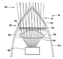
- FIG. 3 illustrates a situation where the missile 10 and a missile 60 are targeting a pair of targets 62 and 64 .
- the missile 10 sends out an encoded laser (optical) signal 66 , encoded with a first encoding scheme.
- the missile 60 sends out a different encoded laser (optical) signal 68 , encoded with a second, different encoding scheme.
- the encoding may be accomplished through any of a wide variety of known methods, such as including high-amplitude pulses at a specified series of intervals. Both of the signals 66 and 68 illuminate both of the targets 62 and 64 .
- the missiles 10 and 60 are targeting different targets, with the missile 10 targeting the first target 62 , and the missile 60 targeting the second target 64 .
- the first encoded signal 66 produces a reflected signal 76 , reflecting off the first target 62 .
- the first encoded signal 66 also produces a reflected signal 77 that is a reflection off of the second target.
- the second encoded signal 68 produces corresponding reflected signals 78 and 79 , reflections off of the targets 62 and 64 , respectively.
- the seeker 46 ( FIG. 1 ) of the first missile 10 is focused on the first target 62 , which the first missile 10 is aiming at.
- the first missile 10 is able to receive both of the reflected signals 76 and 78 that reflect off of the first target 62 .
- the first missile 10 is able to distinguish the reflected signal 76 from the reflected signal 78 (which is not encoded, at least not with the same encoding).
- the missile 10 is thus able to distinguish between the reflected signal 76 that is a reflection of the signal 66 that the missile 10 sent out, and the reflected signal 78 .
- the encoding of the signal 68 allows the missile 60 to be able to distinguish between the reflected signal 79 , which shares the same encoding as the signal 68 , and the reflected signal 77 , which does not.
- the encoding thus allows the missile 10 and 60 to distinguish between signals, and reject for navigation purposes all signals other than signals with the same encoding as the sent signal. Extraneous signals that are rejected may include encoded signals from other missiles (as in the illustrated embodiment), non-encoded signals from other munitions or targeting systems, or even spurious signals deliberately sent in an attempt to confuse targeting systems.
- the missiles 10 and 60 are able to focus only on the reflections of their own signals, which are the reflections of interest for targeting purposes.
- the coding may be used to aid the missile in selecting a target, based on reaction of the coding scheme signal with the target. Different target surfaces will produce different interactions with the coded signals in producing a reflected signal. For example a burning vehicle will be expected to affect the signal (and its coding) differently than would a painted surface of an unburned vehicle.
- the missile 10 may be configured to detect and distinguish different types of reflections of the coded signal 10 . This information may be used in prioritizing and/or selecting targets.
- coded signals as described above is not limited to missiles. It may be possible for the missile 10 to target other sorts of laser-guided munitions, such as laser-guided bombs, that are aimed at the same target that the missile 10 is targeting.
- FIG. 4 shows the free space pattern of signals received by a radar antenna such as main antenna 14 ( FIG. 1 ). This is an ideal result, not taking into account the effects of a radome.
- the three-dimensional plot 100 in FIG. 4 is an indicator of the three-dimensional free space radiation pattern along the bore side of the main antenna 14 .
- the bore side in this case represents the radiation pattern along an axis 102 perpendicular to the surface of the antenna 14 .
- the axis 102 is supposed to be coincident with the axis of the missile 10 .
- the three-dimensional radiation pattern 100 has its maximum value along the axis 102 that corresponds to the direction of travel of the reflected signal. This is to be expected, and allows a missile to be easily directed toward a target (or other aim point).
- the maximum value is the so-called “angle of arrival,” and is an important parameter for the guidance of the missile 10 . By directing the missile 10 toward the location of maximum signal strength, the missile is directed toward the target or other aim point.
- FIGS. 5-7 show a three-dimensional radiation pattern 110 deformed, with an angle ⁇ indicating a degraded angle of arrival, for a system including a prior art radome with a lossy wedge (edge) at its front.
- the presence of the prior art lossy-wedge radome degrades the signal, especially in the vicinity of the axis 102 .
- the signal peak is no longer along the axis 102 , but is offset from the axis 102 by an offset angle ⁇ , which may be for example between 5 and 8 degrees.
- This degradation of signal results in regions of low signal strength—an “RF (radio frequency) hole” in the response received through a prior art radome.
- An example is shown in FIG. 8 at the system level, where the response of a system is poor in a low signal central region 120 where the axis of the missile is pointed, and even poorer in a very low signal region 122 surrounding the central region 120 .
- Another low signal region 124 is located on the outside of the very low signal region 122 .
- a moderate signal strength region 126 begins only well away from the central region 120 .
- FIG. 9 shows a three-dimensional radiation pattern 140 for an embodiment of the present invention which avoids use of a lossy wedge, such as the missile 10 ( FIG. 1 ).
- the signal strength is strongest along the axis 102 , avoiding the offset angle ⁇ shown in FIG. 7 .
- FIG. 10 shows a map showing RF coverage at the system level, with signal strength modeled on the same scale as in FIG. 8 .
- a wide high strength central region 142 takes the place of the low signal regions 120-124 of FIG. 8 .
- the signal strength in this region 142 exceeds that of any of the regions 120-126.
- the high strength region 144 is surrounded by a moderate strength region 146 .
- the good response shown in FIGS. 9 and 10 demonstrates that the radome 16 ( FIG. 1 ) avoids the offset angle and RF hole problems, among other signal degradation problems.
Landscapes
- Engineering & Computer Science (AREA)
- General Engineering & Computer Science (AREA)
- Chemical & Material Sciences (AREA)
- Combustion & Propulsion (AREA)
- Physics & Mathematics (AREA)
- Astronomy & Astrophysics (AREA)
- Aviation & Aerospace Engineering (AREA)
- General Physics & Mathematics (AREA)
- Remote Sensing (AREA)
- Electromagnetism (AREA)
- Aiming, Guidance, Guns With A Light Source, Armor, Camouflage, And Targets (AREA)
Abstract
Description
- 1. Field of the Invention
- The present invention relates to radar systems and methods, such as missile radar systems and methods.
- 2. Description of the Related Art
- Radomes are structures designed to cover antennas and thereby to protect them from direct exposure to aerodynamic and environmental conditions, while being as transparent as possible to the antenna's electromagnetic (EM) radiation. However many types of radomes include various forms of discontinuities or blockages. These discontinuities are not necessarily due to material changes, but in many cases due to shape changes. For example, radomes on high-speed, airborne platforms are usually equipped with a metallic tip to protect the radome against rain, erosion, etc. However there is room for improvement in this field of endeavor.
- The metallic tip is at the very end of a dielectric/lossy edge which is an extension of the radome body, which is also lossy since it is the same material as the radome body. Surfaces inside the radome (cylindrical portion) that are at a certain distance from the main wedge have some blockage of the outgoing RF energy, but the blockage is not significant. Going further forward on the radome, in the region where the wedge begins to form, that part of the wedge acts almost as a metallic entity, especially at higher frequencies. This is because of the lossy material, combined with the wedge (i.e., the shape change), causes a significant blockage of the RF energy transmitted by the main antenna. That RF energy blockage causes a hole in the radiation pattern for the antenna, which is a bad thing since certain areas that are supposed to be covered by the RF energy, are in reality not covered. This lossy wedge, compared to the rest of the radome body which is cylindrical, causes a significant RF blockage, for the incoming or out coming RF energy. This lossy wedge has been found to lead to EM discontinuities for the main antenna located in the back of the radome. An approach to ameliorating these discontinuities, described in detail below, is to add a lossless wedge just before the metallic tip and go backwards between the radome tip and the antenna. This lossless wedge could be transparent glass or non transparent glass. The use of a lossless transparent material also provides the opportunity to introduce optics capabilities in addition to the removal of the radiation pattern hole.
- According to an aspect of an invention, a missile includes different radiatively-transmissive materials in its radome body and its radome tip.
- According to a still further aspect of the invention, a radome has an optically-transmissive tip.
- According to another aspect of the invention, a radome has a tip that is substantially optically transparent.
- According to yet another aspect of the invention, a missile emits encoded laser signals through its radome.
- According to still another aspect of the invention, a missile radar system includes: a main antenna; and a radome enclosing the main antenna. The radome includes a radome body and a radome wedge. The radome body has a wide end and a narrow end, with the main antenna at the wide end, and the radome wedge at the narrow end. The radome wedge and the radome body include different materials that are substantially transparent to radar signals emitted by the main antenna.
- According to a further aspect of the invention, a method of missile target guidance includes the steps of: receiving a reflected signal from an intended target of a missile, wherein the reflected signal is received at a seeker of a missile, after passing through an optically-transparent radome wedge of the missile; examining the reflected signal for the presence of signals not including encoding associated with the missile; and if the reflected signal includes signals including encoding not associated with the missile, rejecting and not using for navigation purposes the signals including encoding not associated with the missile.
- According to a still further aspect of the invention, a method of improving performance of an antenna includes the steps of: providing a radome with a lossless, optically transparent radome wedge and a lossy dielectric radome body; and placing the antenna within the radome.
- According to another aspect of the invention, a missile optical system includes: a radome having an optically transmissive front radome wedge; a seeker that within the radome that sends and receives optical signals on an optical path that passes through the optically transmissive front radome wedge; and one or more lenses in the optical path, between the seeker and the optically transmissive front radome wedge.
- To the accomplishment of the foregoing and related ends, the invention comprises the features hereinafter fully described and particularly pointed out in the claims. The following description and the annexed drawings set forth in detail certain illustrative embodiments of the invention. These embodiments are indicative, however, of but a few of the various ways in which the principles of the invention may be employed. Other objects, advantages and novel features of the invention will become apparent from the following detailed description of the invention when considered in conjunction with the drawings.
- The annexed drawings, which are not necessarily to scale, show various aspects of the invention.
-
FIG. 1 is a cross-sectional view of a missile including a missile radar system in accordance with an embodiment of the present invention. -
FIG. 2 is a cross-section view of part of the missile radar system ofFIG. 1 , showing further details near the tip of the missile. -
FIG. 3 is a schematic diagram illustrating employment of the missile radar system ofFIG. 1 in a situation where two missiles are targeting separate targets. -
FIG. 4 is a diagram illustrating the free space signal strength of signals received by an antenna such as the main antenna of the missile radar system ofFIG. 1 , in the absence of a radome. -
FIG. 5 is a diagram illustrating the free space signal strength of signals received by an antenna such as the main antenna of the missile radar system ofFIG. 1 , in the presence of a prior art radome having a lossy non transparent wedge (or edge). -
FIG. 6 is a diagram illustrating the signal strength in the presence of a prior art radome having a lossy non transparent wedge (or edge). -
FIG. 7 is another diagram illustrating the signal strength in the presence of a prior art radome having a lossy non transparent wedge (or edge). -
FIG. 8 is a plot illustrating radar strength in an example RF coverage area scanned by a radar system utilizing a prior art radome having a lossy non transparent wedge (or edge). -
FIG. 9 is a diagram illustrating the signal strength in the presence of a radome according to an embodiment of the present invention indicating the improvement of the angle of arrival. -
FIG. 10 is a plot illustrating radar strength in an example of RF coverage area (system level) scanned by a radar system utilizing a radome according to an embodiment of the present invention. - A missile includes a radar system that has a radome through which a main antenna sends and receives signals. The radome includes a radome body at a relatively wide area of the radome, and a radome tip at a relatively narrow end of the radome, with the tip including the apex (edge) of the radome (the forward-most part of the radome). The radome body and the radome tip include different transmissive materials, with for example the radome body primarily made of a lossy optically nontransparent material, and the radome tip primarily made of a lossless (permittivity with low imaginary part) glass material that may also be optically transparent. A laser may be used in conjunction with the radome to send and receive encoded signals. The laser may be located behind (aft of) the main antenna, and one or more optical fibers may extend into and/or along the radome to guide laser signals to the radome tip. The laser may be used to emit encoded signals so as to allow multiple radar systems operating in the same area at the same time to discriminate between different targets.
-
FIG. 1 shows a portion of amissile 10 that has aradar system 12 that includes amain antenna 14 that is enclosed by aradome 16. Theradome 16 has aradome body 20 and a radome wedge (edge) 22. Theradome body 20 is at the aft end of theradome 16, where the radarmain antenna 14 is located. Theradome body 20 may be made of a conventional radome material, such as a ceramic, that to is substantially radiatively transmissive or transparent, so as to allow radar signals to pass into and out of theradome 16. Theradome body 20 has a tapered shape, being wider at its aft end, and narrower at its front end, where it connects to the radome wedge (edge) 22. Theradome body 20 may have any of a variety of suitable shapes, for example having a conical shape or an ogive-like shape. - The radome wedge (edge) 22 is also at least partially transparent to radiation emitted by and/or received by the
antenna 14. Thus the radome wedge (edge) 22 may also be described as radiatively transmissive or optically transparent. However the radome wedge (edge) 22 includes a different material than theradome body 20. This may be an optically transparent material, such as a suitable glass, to make the radome wedge (edge) 22 optically transparent. The optical transparency may be to allow light to pass through the radome wedge (edge) 22, for example laser light, such as laser encoded signals, as described further below. It will also be appreciated that the radome wedge (edge) 22 may have a different material in order to withstand the forces it receives at the very front of themissile 10, which may result in heating beyond that experienced by theradome body 20. The glass of the radome wedge (edge) 22 may be suitable for the heat build-up and other environmental characteristics that will be encountered at the very front of themissile 12. - A
metal tip 24 may be located at the front of theradome wedge 22. Themetal tip 24 may serve to protect theradome 16 against rain or erosion, for instance. - More detailed explanations are now provided regarding the materials of the
radome body 20 and theradome wedge 22. Theradome body 20 is made of a lossy optically nontransparent dielectric material. Certain ceramics are examples of suitable lossy optically nontransparent dielectric materials. Theradome wedge 22, in contrast, is made of a lossless dielectric, which includes very low lossy dielectric material, where the imaginary part of the dielectric constant is very low. The material of theradome wedge 22 may also be optically transparent. Certain glasses are examples of suitable materials for theradome wedge 22. - As used herein a “lossless material” or “lossless dielectric material” is a material for which
-
- where σ is the electrical conductivity of medium (material), ∈ is the permittivity of medium, and ω is radian frequency, which is 2πf, where f is the frequency. A “lossy material” of “lossy dielectric material” is a material for which
-
- A “conductive material” is a material for which
-
- For purposes of these definitions a representative frequency f of 3 GHz may be used. Radomes such as those described herein may be used for frequencies in the range of 3-200 GHz, although these values should not be taken as limiting.
- The
radome body 20 and the radome wedge (edge) 22 may be coupled together by any of a variety of suitable means or methods. To give one example, the radome wedge (edge) 22 may be adhesively coupled to theradome body 20 using a suitable adhesive. Brazing is another method/means by which theradome body 20 and the radome wedge (edge) 22 may be coupled together. As another alternative, theradome body 20 and the radome wedge (edge) 22 may be parts of a single unitary continuous piece, for example formed in a single piece by diffusion of the materials of theradome body 20 and theradome wedge 22, such as occurs under elevated temperature. There may be a region along the border between theradome body 20 and the radome wedge (edge) 22 in which materials used in both thebody 20 and the wedge (edge) 22 are present. There may be a material gradient near (in a vicinity of) aboundary 30 between thebody 20 and wedge (edge) 22, with a gradual material change in aboundary region 32 from that of theradome body 20 to that of the radome wedge (edge) 22. - A
laser 40 is located aft of themain antenna 14. Thelaser 40 is used to send encoded signals to illuminate a target of themissile 10. The signals are sent from thelaser 40 along one or moreoptical fibers 42 that extend from thelaser 40 to the radome wedge (edge) 22. The optical fiber(s) 42 may extend along the inner surface of theradome 16, and may be located at least partially within the material of theradome 16. Theoptical fibers 42 may be grouped in optical fiber bundles. Thelaser 40 and the optical fiber(s) 42 together may be considered to function as alaser designator 44, an optical emitter that illuminates the intended target with an encoded laser signal. For example the encoding may be contained in an encoded pulse train. The length of pulses, the pauses between pulses, and/or the intensity of pulses, may constitute an identifier or code substantially unique to themissile 10, and different from encoding utilized by other munitions. The reflected laser light (“sparkle”) from the intended target may be detected by a semi-active laser (SAL)seeker 46 that is located inside the radome wedge (edge) 22. TheSAL seeker 46 may be or may include a bundle of optical fibers. Some of theoptical fibers 42 may be used for transmitting signals from theseeker 46 to other components of themissile 10, such as aquad detector 48 or other suitable components aft of themain antenna 14, located in afuselage 49 of themissile 10. Thequad detector 48 may be used for detecting encoded pulse or other identifiers in incoming light signals, as described further below. - By detecting the encoding in the reflection of the encoded laser signals the fact that the
missile 10 is targeting the illuminated target may be determinable by other missiles/munitions. Receipt by theseeker 46 of encoded signals having different encoding than the signals sent by themissile 10 indicates that another missile or other munition may be targeting the same target. This information may be useful in avoiding having multiple missiles/munitions targeting the same target. -
FIG. 2 shows further details of the setup for theseeker 46. TheSAL seeker 46 is within or behind the radome wedge (edge) 22, receivingincoming signals 50 that pass through the radome wedge (edge) 22. The incomingoptical signals 50, as well as outgoing optical signals passing through the optically-transmissive radome wedge 22, travel along anoptical path 51. Between the radome wedge (edge) 22 and theseeker 46 are afilter 52 and anSAL lens 54. Thefiler 52, which may be omitted, may aid in filtering laser light, in order to reduce reflections within theradome 16. TheSAL lens 54 aids in focusing incoming light onto theseeker 46. More than one lens may be employed in focusing the incoming light. - The
filter 52 and theSAL lens 54 may be mechanically coupled to theradome 16 using anonmetallic structure 56. Thenonmetallic structure 56 may be made of a suitable nonmetallic material, such as a suitable ceramic. Using a nonmetallic material for thestructure 56 avoids interference in radar signals that would occur if a metallic structure was used. -
FIG. 3 illustrates a situation where themissile 10 and amissile 60 are targeting a pair oftargets missile 10 sends out an encoded laser (optical)signal 66, encoded with a first encoding scheme. Themissile 60 sends out a different encoded laser (optical)signal 68, encoded with a second, different encoding scheme. The encoding may be accomplished through any of a wide variety of known methods, such as including high-amplitude pulses at a specified series of intervals. Both of thesignals targets missiles missile 10 targeting thefirst target 62, and themissile 60 targeting thesecond target 64. The first encodedsignal 66 produces a reflectedsignal 76, reflecting off thefirst target 62. The first encodedsignal 66 also produces a reflectedsignal 77 that is a reflection off of the second target. The second encodedsignal 68 produces corresponding reflected signals 78 and 79, reflections off of thetargets - The seeker 46 (
FIG. 1 ) of thefirst missile 10 is focused on thefirst target 62, which thefirst missile 10 is aiming at. Thefirst missile 10 is able to receive both of the reflected signals 76 and 78 that reflect off of thefirst target 62. However, because of the encoding in the encodedsignal 66, which is also present in the corresponding reflectedsignal 76, thefirst missile 10 is able to distinguish the reflectedsignal 76 from the reflected signal 78 (which is not encoded, at least not with the same encoding). Themissile 10 is thus able to distinguish between the reflectedsignal 76 that is a reflection of thesignal 66 that themissile 10 sent out, and the reflectedsignal 78. Similarly, the encoding of thesignal 68 allows themissile 60 to be able to distinguish between the reflectedsignal 79, which shares the same encoding as thesignal 68, and the reflectedsignal 77, which does not. - The encoding thus allows the
missile missiles - In addition, the coding may be used to aid the missile in selecting a target, based on reaction of the coding scheme signal with the target. Different target surfaces will produce different interactions with the coded signals in producing a reflected signal. For example a burning vehicle will be expected to affect the signal (and its coding) differently than would a painted surface of an unburned vehicle. The
missile 10 may be configured to detect and distinguish different types of reflections of the codedsignal 10. This information may be used in prioritizing and/or selecting targets. - The use of coded signals as described above is not limited to missiles. It may be possible for the
missile 10 to target other sorts of laser-guided munitions, such as laser-guided bombs, that are aimed at the same target that themissile 10 is targeting. - In addition to the advantages for allowing sending and receiving of optical signals, the
radome 20 described above provides advantages in receiving radar signals, by avoiding radar signal degradation that occurred in prior art systems.FIG. 4 shows the free space pattern of signals received by a radar antenna such as main antenna 14 (FIG. 1 ). This is an ideal result, not taking into account the effects of a radome. The three-dimensional plot 100 inFIG. 4 is an indicator of the three-dimensional free space radiation pattern along the bore side of themain antenna 14. The bore side in this case represents the radiation pattern along anaxis 102 perpendicular to the surface of theantenna 14. When themain antenna 14 is located in the missile 10 (FIG. 1 ), theaxis 102 is supposed to be coincident with the axis of themissile 10. The three-dimensional radiation pattern 100 has its maximum value along theaxis 102 that corresponds to the direction of travel of the reflected signal. This is to be expected, and allows a missile to be easily directed toward a target (or other aim point). The maximum value is the so-called “angle of arrival,” and is an important parameter for the guidance of themissile 10. By directing themissile 10 toward the location of maximum signal strength, the missile is directed toward the target or other aim point. - Unfortunately the signal strength does not have the ideal shape indicated in
FIG. 4 .FIGS. 5-7 show a three-dimensional radiation pattern 110 deformed, with an angle θ indicating a degraded angle of arrival, for a system including a prior art radome with a lossy wedge (edge) at its front. The presence of the prior art lossy-wedge radome degrades the signal, especially in the vicinity of theaxis 102. As best seen inFIG. 7 , the signal peak is no longer along theaxis 102, but is offset from theaxis 102 by an offset angle θ, which may be for example between 5 and 8 degrees. This degradation of signal results in regions of low signal strength—an “RF (radio frequency) hole” in the response received through a prior art radome. An example is shown inFIG. 8 at the system level, where the response of a system is poor in a low signalcentral region 120 where the axis of the missile is pointed, and even poorer in a verylow signal region 122 surrounding thecentral region 120. Anotherlow signal region 124 is located on the outside of the verylow signal region 122. A moderatesignal strength region 126 begins only well away from thecentral region 120. -
FIG. 9 shows a three-dimensional radiation pattern 140 for an embodiment of the present invention which avoids use of a lossy wedge, such as the missile 10 (FIG. 1 ). The signal strength is strongest along theaxis 102, avoiding the offset angle θ shown inFIG. 7 .FIG. 10 shows a map showing RF coverage at the system level, with signal strength modeled on the same scale as inFIG. 8 . A wide high strengthcentral region 142 takes the place of the low signal regions 120-124 ofFIG. 8 . The signal strength in thisregion 142 exceeds that of any of the regions 120-126. Thehigh strength region 144 is surrounded by amoderate strength region 146. The good response shown inFIGS. 9 and 10 demonstrates that the radome 16 (FIG. 1 ) avoids the offset angle and RF hole problems, among other signal degradation problems. - From the foregoing it will be appreciated that many aspects of the present invention provide significant advantages over prior systems. Avoiding a lossy wedge (edge) prevents degradation of the signal strength of signals received by the missile's main antenna. Not only is a general degradation of signal strength prevented, but the problems of peak offset and low strength regions (RF holes) are avoided. In addition the angle of arrival is also corrected. The use of a substantially optically transparent radome tip allows employment of optical imaging through the radome. The employment of a seeker allows for designation of a specific target that the RF-guided missile should strike. The use of a seeker, in conjunction with a laser for illuminating the target, increases the precision of guidance toward a desired target. It also enables flexibility in targeting, and fast-reaction targeting. Finally, the use of encoded laser signals allows detection by the missile of situations where multiple munitions are aimed at the same target. Furthermore the use of encoded optical signals allows the missile to select and prioritize targets dynamically or based on priory information for certain targets.
- Although the invention has been shown and described with respect to a certain preferred embodiment or embodiments, it is obvious that equivalent alterations and modifications will occur to others skilled in the art upon the reading and understanding of this specification and the annexed drawings. In particular regard to the various functions performed by the above described elements (components, assemblies, devices, compositions, etc.), the terms (including a reference to a “means”) used to describe such elements are intended to correspond, unless otherwise indicated, to any element which performs the specified function of the described element (i.e., that is functionally equivalent), even though not structurally equivalent to the disclosed structure which performs the function in the herein illustrated exemplary embodiment or embodiments of the invention. In addition, while a particular feature of the invention may have been described above with respect to only one or more of several illustrated embodiments, such feature may be combined with one or more other features of the other embodiments, as may be desired and advantageous for any given or particular application.
Claims (21)
Priority Applications (1)
| Application Number | Priority Date | Filing Date | Title |
|---|---|---|---|
| US13/076,836 US8773300B2 (en) | 2011-03-31 | 2011-03-31 | Antenna/optics system and method |
Applications Claiming Priority (1)
| Application Number | Priority Date | Filing Date | Title |
|---|---|---|---|
| US13/076,836 US8773300B2 (en) | 2011-03-31 | 2011-03-31 | Antenna/optics system and method |
Publications (2)
| Publication Number | Publication Date |
|---|---|
| US20120249357A1 true US20120249357A1 (en) | 2012-10-04 |
| US8773300B2 US8773300B2 (en) | 2014-07-08 |
Family
ID=46926479
Family Applications (1)
| Application Number | Title | Priority Date | Filing Date |
|---|---|---|---|
| US13/076,836 Active 2032-10-30 US8773300B2 (en) | 2011-03-31 | 2011-03-31 | Antenna/optics system and method |
Country Status (1)
| Country | Link |
|---|---|
| US (1) | US8773300B2 (en) |
Cited By (7)
| Publication number | Priority date | Publication date | Assignee | Title |
|---|---|---|---|---|
| US20120249358A1 (en) * | 2011-03-31 | 2012-10-04 | Stratis Glafkos K | Dynamic calibration radar system |
| US8773300B2 (en) * | 2011-03-31 | 2014-07-08 | Raytheon Company | Antenna/optics system and method |
| US20170160057A1 (en) * | 2015-08-12 | 2017-06-08 | Kongsberg Defence & Aerospace As | Method and system for planning and launching a plurality of missiles to be included in the same mission |
| WO2018195542A1 (en) * | 2017-04-21 | 2018-10-25 | The Board Of Regents Of The University Of Oklahoma | Apparatus and method(s) for wet radome characterization and radar calibration |
| US11175379B2 (en) * | 2018-02-28 | 2021-11-16 | Baumer Electric Ag | Housing arrangement for a radar sensor |
| US20220080617A1 (en) * | 2019-01-09 | 2022-03-17 | Aselsan Elektronik Sanayi Ve Ticaret Anonim Sirketi | Three-dimensional printing of multilayer ceramic missile radomes by using interlayer transition materials |
| WO2025008986A1 (en) * | 2023-07-06 | 2025-01-09 | Jio Platforms Limited | Antenna module for mmwave radio systems |
Families Citing this family (4)
| Publication number | Priority date | Publication date | Assignee | Title |
|---|---|---|---|---|
| IL233924B (en) * | 2014-08-03 | 2019-08-29 | Israel Aerospace Ind Ltd | Protective dome for a dual mode electromagnetic detection system |
| JP2020008389A (en) * | 2018-07-06 | 2020-01-16 | 豊田合成株式会社 | Vehicle sensor unit |
| US11349201B1 (en) * | 2019-01-24 | 2022-05-31 | Northrop Grumman Systems Corporation | Compact antenna system for munition |
| US12560409B1 (en) * | 2024-08-20 | 2026-02-24 | Optex Systems, Inc. | Laser filter antenna |
Citations (28)
| Publication number | Priority date | Publication date | Assignee | Title |
|---|---|---|---|---|
| US3115271A (en) * | 1958-08-15 | 1963-12-24 | Minnesota Mining & Mfg | Method of constructing a reinforced resin, cone-shaped structure and product |
| US3396396A (en) * | 1965-11-30 | 1968-08-06 | Air Force Usa | Aircraft nose radome with ceramic cover mounted on metallic framework |
| US3576581A (en) * | 1968-08-15 | 1971-04-27 | Gen Dynamics Corp | Radomes |
| US3979755A (en) * | 1974-12-17 | 1976-09-07 | The United States Of America As Represented By The Secretary Of The Army | Rotating lens antenna seeker-head |
| US4189731A (en) * | 1978-06-12 | 1980-02-19 | General Dynamics Electronics Division | Radome with tilted dielectric strips |
| US4386356A (en) * | 1979-10-17 | 1983-05-31 | General Dynamics/Electronics Division | Antenna system employing a self-referencing microwave interferometer for direction finding |
| JPS58177004A (en) * | 1982-04-09 | 1983-10-17 | Mitsubishi Electric Corp | Fitting method of radome to antenna |
| US4570166A (en) * | 1983-08-29 | 1986-02-11 | General Electric Company | RF-Transparent shield structures |
| US4949920A (en) * | 1989-12-14 | 1990-08-21 | The United States Of America As Represented By The Secretary Of The Navy | Ablative cooling of aerodynamically heated radomes |
| US4989007A (en) * | 1986-02-10 | 1991-01-29 | Her Majesty In Right Of Canada, As Represented By The Minister Of National Defence | Passive radar augmented projectile (PRAP) |
| US5191351A (en) * | 1989-12-29 | 1993-03-02 | Texas Instruments Incorporated | Folded broadband antenna with a symmetrical pattern |
| JPH06313699A (en) * | 1993-04-30 | 1994-11-08 | Mitsubishi Heavy Ind Ltd | Radome |
| US5384458A (en) * | 1992-09-30 | 1995-01-24 | The United States Of America As Represented By The Secretary Of The Navy | Photonic electromagnetic field sensor for use in a missile |
| US5686929A (en) * | 1994-10-25 | 1997-11-11 | Siemens Aktiengesellschaft | RF homing head antenna system for missiles |
| US5724052A (en) * | 1988-06-14 | 1998-03-03 | Thomson-Csf | Device for reducing the radome effect with a surface-radiating wideband antenna and reducing the radar cross section of the assembly |
| US5835062A (en) * | 1996-11-01 | 1998-11-10 | Harris Corporation | Flat panel-configured electronically steerable phased array antenna having spatially distributed array of fanned dipole sub-arrays controlled by triode-configured field emission control devices |
| US6060703A (en) * | 1998-06-29 | 2000-05-09 | Alliant Defense Electronics Systems, Inc. | Coaxial unfocused optical sensor for dual mode seekers |
| US6107976A (en) * | 1999-03-25 | 2000-08-22 | Bradley B. Teel | Hybrid core sandwich radome |
| US6150974A (en) * | 1982-05-17 | 2000-11-21 | The United States Of America As Represented By The Secretary Of The Navy | Infrared transparent radar antenna |
| US6342860B1 (en) * | 2001-02-09 | 2002-01-29 | Centurion Wireless Technologies | Micro-internal antenna |
| US6531989B1 (en) * | 2001-11-14 | 2003-03-11 | Raytheon Company | Far field emulator for antenna calibration |
| US6952179B1 (en) * | 1988-01-26 | 2005-10-04 | Bae Systems Electronics Limited | Radar system |
| US20090213019A1 (en) * | 2005-07-18 | 2009-08-27 | Robert Bosh Gmbh | Antenna Device Having A Radome For Installation In A Motor Vehicle |
| US7595765B1 (en) * | 2006-06-29 | 2009-09-29 | Ball Aerospace & Technologies Corp. | Embedded surface wave antenna with improved frequency bandwidth and radiation performance |
| US20100058946A1 (en) * | 2008-09-08 | 2010-03-11 | Geswender Chris E | Smart fuze guidance system with replaceable fuze module |
| US20120212391A1 (en) * | 2009-09-11 | 2012-08-23 | Airbus Operations (S.A.S) | Radome and device for attaching said radome to an aircraft |
| US8264405B2 (en) * | 2008-07-31 | 2012-09-11 | Raytheon Company | Methods and apparatus for radiator for multiple circular polarization |
| US20120249358A1 (en) * | 2011-03-31 | 2012-10-04 | Stratis Glafkos K | Dynamic calibration radar system |
Family Cites Families (3)
| Publication number | Priority date | Publication date | Assignee | Title |
|---|---|---|---|---|
| IL107506A (en) | 1993-11-05 | 1998-02-08 | State Rafael Armamentry Of Def | Method and apparatus for reducing sidelobes of antennas within radomes |
| US5973649A (en) | 1997-10-28 | 1999-10-26 | Alliant Techsystems, Inc. | Common aperture dual mode semi-active laser/millimeter wave sensor |
| US8773300B2 (en) * | 2011-03-31 | 2014-07-08 | Raytheon Company | Antenna/optics system and method |
-
2011
- 2011-03-31 US US13/076,836 patent/US8773300B2/en active Active
Patent Citations (28)
| Publication number | Priority date | Publication date | Assignee | Title |
|---|---|---|---|---|
| US3115271A (en) * | 1958-08-15 | 1963-12-24 | Minnesota Mining & Mfg | Method of constructing a reinforced resin, cone-shaped structure and product |
| US3396396A (en) * | 1965-11-30 | 1968-08-06 | Air Force Usa | Aircraft nose radome with ceramic cover mounted on metallic framework |
| US3576581A (en) * | 1968-08-15 | 1971-04-27 | Gen Dynamics Corp | Radomes |
| US3979755A (en) * | 1974-12-17 | 1976-09-07 | The United States Of America As Represented By The Secretary Of The Army | Rotating lens antenna seeker-head |
| US4189731A (en) * | 1978-06-12 | 1980-02-19 | General Dynamics Electronics Division | Radome with tilted dielectric strips |
| US4386356A (en) * | 1979-10-17 | 1983-05-31 | General Dynamics/Electronics Division | Antenna system employing a self-referencing microwave interferometer for direction finding |
| JPS58177004A (en) * | 1982-04-09 | 1983-10-17 | Mitsubishi Electric Corp | Fitting method of radome to antenna |
| US6150974A (en) * | 1982-05-17 | 2000-11-21 | The United States Of America As Represented By The Secretary Of The Navy | Infrared transparent radar antenna |
| US4570166A (en) * | 1983-08-29 | 1986-02-11 | General Electric Company | RF-Transparent shield structures |
| US4989007A (en) * | 1986-02-10 | 1991-01-29 | Her Majesty In Right Of Canada, As Represented By The Minister Of National Defence | Passive radar augmented projectile (PRAP) |
| US6952179B1 (en) * | 1988-01-26 | 2005-10-04 | Bae Systems Electronics Limited | Radar system |
| US5724052A (en) * | 1988-06-14 | 1998-03-03 | Thomson-Csf | Device for reducing the radome effect with a surface-radiating wideband antenna and reducing the radar cross section of the assembly |
| US4949920A (en) * | 1989-12-14 | 1990-08-21 | The United States Of America As Represented By The Secretary Of The Navy | Ablative cooling of aerodynamically heated radomes |
| US5191351A (en) * | 1989-12-29 | 1993-03-02 | Texas Instruments Incorporated | Folded broadband antenna with a symmetrical pattern |
| US5384458A (en) * | 1992-09-30 | 1995-01-24 | The United States Of America As Represented By The Secretary Of The Navy | Photonic electromagnetic field sensor for use in a missile |
| JPH06313699A (en) * | 1993-04-30 | 1994-11-08 | Mitsubishi Heavy Ind Ltd | Radome |
| US5686929A (en) * | 1994-10-25 | 1997-11-11 | Siemens Aktiengesellschaft | RF homing head antenna system for missiles |
| US5835062A (en) * | 1996-11-01 | 1998-11-10 | Harris Corporation | Flat panel-configured electronically steerable phased array antenna having spatially distributed array of fanned dipole sub-arrays controlled by triode-configured field emission control devices |
| US6060703A (en) * | 1998-06-29 | 2000-05-09 | Alliant Defense Electronics Systems, Inc. | Coaxial unfocused optical sensor for dual mode seekers |
| US6107976A (en) * | 1999-03-25 | 2000-08-22 | Bradley B. Teel | Hybrid core sandwich radome |
| US6342860B1 (en) * | 2001-02-09 | 2002-01-29 | Centurion Wireless Technologies | Micro-internal antenna |
| US6531989B1 (en) * | 2001-11-14 | 2003-03-11 | Raytheon Company | Far field emulator for antenna calibration |
| US20090213019A1 (en) * | 2005-07-18 | 2009-08-27 | Robert Bosh Gmbh | Antenna Device Having A Radome For Installation In A Motor Vehicle |
| US7595765B1 (en) * | 2006-06-29 | 2009-09-29 | Ball Aerospace & Technologies Corp. | Embedded surface wave antenna with improved frequency bandwidth and radiation performance |
| US8264405B2 (en) * | 2008-07-31 | 2012-09-11 | Raytheon Company | Methods and apparatus for radiator for multiple circular polarization |
| US20100058946A1 (en) * | 2008-09-08 | 2010-03-11 | Geswender Chris E | Smart fuze guidance system with replaceable fuze module |
| US20120212391A1 (en) * | 2009-09-11 | 2012-08-23 | Airbus Operations (S.A.S) | Radome and device for attaching said radome to an aircraft |
| US20120249358A1 (en) * | 2011-03-31 | 2012-10-04 | Stratis Glafkos K | Dynamic calibration radar system |
Cited By (11)
| Publication number | Priority date | Publication date | Assignee | Title |
|---|---|---|---|---|
| US20120249358A1 (en) * | 2011-03-31 | 2012-10-04 | Stratis Glafkos K | Dynamic calibration radar system |
| US8416127B2 (en) * | 2011-03-31 | 2013-04-09 | Raytheon Company | Dynamic calibration radar system |
| US8773300B2 (en) * | 2011-03-31 | 2014-07-08 | Raytheon Company | Antenna/optics system and method |
| US20170160057A1 (en) * | 2015-08-12 | 2017-06-08 | Kongsberg Defence & Aerospace As | Method and system for planning and launching a plurality of missiles to be included in the same mission |
| US9958237B2 (en) * | 2015-08-12 | 2018-05-01 | Kongsberg Defence & Aerospace As | Method and system for planning and launching a plurality of missiles to be included in the same mission |
| WO2018195542A1 (en) * | 2017-04-21 | 2018-10-25 | The Board Of Regents Of The University Of Oklahoma | Apparatus and method(s) for wet radome characterization and radar calibration |
| US20200049751A1 (en) * | 2017-04-21 | 2020-02-13 | The Board Of Regents Of The University Of Oklahoma | Apparatus and method(s) for wet radome characterization and radar calibration |
| US11796580B2 (en) * | 2017-04-21 | 2023-10-24 | The Board Of Regents Of The University Of Oklahoma | Apparatus and method(s) for wet radome characterization and radar calibration |
| US11175379B2 (en) * | 2018-02-28 | 2021-11-16 | Baumer Electric Ag | Housing arrangement for a radar sensor |
| US20220080617A1 (en) * | 2019-01-09 | 2022-03-17 | Aselsan Elektronik Sanayi Ve Ticaret Anonim Sirketi | Three-dimensional printing of multilayer ceramic missile radomes by using interlayer transition materials |
| WO2025008986A1 (en) * | 2023-07-06 | 2025-01-09 | Jio Platforms Limited | Antenna module for mmwave radio systems |
Also Published As
| Publication number | Publication date |
|---|---|
| US8773300B2 (en) | 2014-07-08 |
Similar Documents
| Publication | Publication Date | Title |
|---|---|---|
| US8773300B2 (en) | Antenna/optics system and method | |
| CN201298079Y (en) | Laser range finding apparatus | |
| US4247858A (en) | Antennas for use with optical and high-frequency radiation | |
| US7336345B2 (en) | LADAR system with SAL follower | |
| US8474172B2 (en) | Alert RF system for hunter protection | |
| US6225955B1 (en) | Dual-mode, common-aperture antenna system | |
| WO2017033662A1 (en) | Radar device | |
| CN110487120B (en) | Laser defense system and method for remote illumination | |
| US11493603B2 (en) | LIDAR sensor for detecting an object | |
| US20130099895A1 (en) | System and method for friend identification | |
| EP4063722A1 (en) | Light emitting unit, and lamp device | |
| US6281968B1 (en) | Laser distance-measuring instrument for large measuring ranges | |
| EP0982559A2 (en) | Coaxial unfocused optical sensor for dual mode seekers | |
| CN206960659U (en) | A kind of sounding optical system | |
| CN105393472B (en) | The method and apparatus that optics energy is extracted from light beam | |
| CN105044729A (en) | Raman scattering laser radar used for aircraft detection | |
| US9568280B1 (en) | Solid nose cone and related components | |
| KR101702204B1 (en) | Signal jamming System for Semi-active Homing guided anti-tank missile | |
| CN110596673B (en) | Coaxial lidar system | |
| CN113701577B (en) | Layout method of active laser and active millimeter wave common-caliber composite detection device | |
| CN113030910A (en) | Laser radar system | |
| CN109270514A (en) | A kind of double optical-fiber laser radar systems for realizing the low blind area detection of double-view field | |
| CN117129970A (en) | LiDAR receiving system and LiDAR | |
| CN115524857A (en) | Optical system and laser radar having the same | |
| CN115327791A (en) | Optical system and laser radar with same |
Legal Events
| Date | Code | Title | Description |
|---|---|---|---|
| AS | Assignment |
Owner name: RAYTHEON COMPANY, MASSACHUSETTS Free format text: ASSIGNMENT OF ASSIGNORS INTEREST;ASSIGNORS:STRATIS, GLAFKOS K;SAMUEL, ALPHONSO A;BELLOFIORE, SALVATORE;AND OTHERS;SIGNING DATES FROM 20110328 TO 20110330;REEL/FRAME:026054/0145 |
|
| FEPP | Fee payment procedure |
Free format text: PAYOR NUMBER ASSIGNED (ORIGINAL EVENT CODE: ASPN); ENTITY STATUS OF PATENT OWNER: LARGE ENTITY |
|
| STCF | Information on status: patent grant |
Free format text: PATENTED CASE |
|
| MAFP | Maintenance fee payment |
Free format text: PAYMENT OF MAINTENANCE FEE, 4TH YEAR, LARGE ENTITY (ORIGINAL EVENT CODE: M1551) Year of fee payment: 4 |
|
| MAFP | Maintenance fee payment |
Free format text: PAYMENT OF MAINTENANCE FEE, 8TH YEAR, LARGE ENTITY (ORIGINAL EVENT CODE: M1552); ENTITY STATUS OF PATENT OWNER: LARGE ENTITY Year of fee payment: 8 |
|
| MAFP | Maintenance fee payment |
Free format text: PAYMENT OF MAINTENANCE FEE, 12TH YEAR, LARGE ENTITY (ORIGINAL EVENT CODE: M1553); ENTITY STATUS OF PATENT OWNER: LARGE ENTITY Year of fee payment: 12 |