US20120249081A1 - Balanced energy and energy producing system - Google Patents
Balanced energy and energy producing system Download PDFInfo
- Publication number
- US20120249081A1 US20120249081A1 US13/435,516 US201213435516A US2012249081A1 US 20120249081 A1 US20120249081 A1 US 20120249081A1 US 201213435516 A US201213435516 A US 201213435516A US 2012249081 A1 US2012249081 A1 US 2012249081A1
- Authority
- US
- United States
- Prior art keywords
- output device
- generator
- parameters
- control device
- strength
- Prior art date
- Legal status (The legal status is an assumption and is not a legal conclusion. Google has not performed a legal analysis and makes no representation as to the accuracy of the status listed.)
- Abandoned
Links
Images


Classifications
-
- F—MECHANICAL ENGINEERING; LIGHTING; HEATING; WEAPONS; BLASTING
- F03—MACHINES OR ENGINES FOR LIQUIDS; WIND, SPRING, OR WEIGHT MOTORS; PRODUCING MECHANICAL POWER OR A REACTIVE PROPULSIVE THRUST, NOT OTHERWISE PROVIDED FOR
- F03D—WIND MOTORS
- F03D9/00—Adaptations of wind motors for special use; Combinations of wind motors with apparatus driven thereby; Wind motors specially adapted for installation in particular locations
- F03D9/007—Adaptations of wind motors for special use; Combinations of wind motors with apparatus driven thereby; Wind motors specially adapted for installation in particular locations the wind motor being combined with means for converting solar radiation into useful energy
-
- B—PERFORMING OPERATIONS; TRANSPORTING
- B60—VEHICLES IN GENERAL
- B60L—PROPULSION OF ELECTRICALLY-PROPELLED VEHICLES; SUPPLYING ELECTRIC POWER FOR AUXILIARY EQUIPMENT OF ELECTRICALLY-PROPELLED VEHICLES; ELECTRODYNAMIC BRAKE SYSTEMS FOR VEHICLES IN GENERAL; MAGNETIC SUSPENSION OR LEVITATION FOR VEHICLES; MONITORING OPERATING VARIABLES OF ELECTRICALLY-PROPELLED VEHICLES; ELECTRIC SAFETY DEVICES FOR ELECTRICALLY-PROPELLED VEHICLES
- B60L50/00—Electric propulsion with power supplied within the vehicle
- B60L50/20—Electric propulsion with power supplied within the vehicle using propulsion power generated by humans or animals
-
- B—PERFORMING OPERATIONS; TRANSPORTING
- B60—VEHICLES IN GENERAL
- B60L—PROPULSION OF ELECTRICALLY-PROPELLED VEHICLES; SUPPLYING ELECTRIC POWER FOR AUXILIARY EQUIPMENT OF ELECTRICALLY-PROPELLED VEHICLES; ELECTRODYNAMIC BRAKE SYSTEMS FOR VEHICLES IN GENERAL; MAGNETIC SUSPENSION OR LEVITATION FOR VEHICLES; MONITORING OPERATING VARIABLES OF ELECTRICALLY-PROPELLED VEHICLES; ELECTRIC SAFETY DEVICES FOR ELECTRICALLY-PROPELLED VEHICLES
- B60L50/00—Electric propulsion with power supplied within the vehicle
- B60L50/50—Electric propulsion with power supplied within the vehicle using propulsion power supplied by batteries or fuel cells
- B60L50/60—Electric propulsion with power supplied within the vehicle using propulsion power supplied by batteries or fuel cells using power supplied by batteries
- B60L50/61—Electric propulsion with power supplied within the vehicle using propulsion power supplied by batteries or fuel cells using power supplied by batteries by batteries charged by engine-driven generators, e.g. series hybrid electric vehicles
- B60L50/62—Electric propulsion with power supplied within the vehicle using propulsion power supplied by batteries or fuel cells using power supplied by batteries by batteries charged by engine-driven generators, e.g. series hybrid electric vehicles charged by low-power generators primarily intended to support the batteries, e.g. range extenders
-
- B—PERFORMING OPERATIONS; TRANSPORTING
- B60—VEHICLES IN GENERAL
- B60L—PROPULSION OF ELECTRICALLY-PROPELLED VEHICLES; SUPPLYING ELECTRIC POWER FOR AUXILIARY EQUIPMENT OF ELECTRICALLY-PROPELLED VEHICLES; ELECTRODYNAMIC BRAKE SYSTEMS FOR VEHICLES IN GENERAL; MAGNETIC SUSPENSION OR LEVITATION FOR VEHICLES; MONITORING OPERATING VARIABLES OF ELECTRICALLY-PROPELLED VEHICLES; ELECTRIC SAFETY DEVICES FOR ELECTRICALLY-PROPELLED VEHICLES
- B60L50/00—Electric propulsion with power supplied within the vehicle
- B60L50/50—Electric propulsion with power supplied within the vehicle using propulsion power supplied by batteries or fuel cells
- B60L50/60—Electric propulsion with power supplied within the vehicle using propulsion power supplied by batteries or fuel cells using power supplied by batteries
- B60L50/66—Arrangements of batteries
-
- F—MECHANICAL ENGINEERING; LIGHTING; HEATING; WEAPONS; BLASTING
- F03—MACHINES OR ENGINES FOR LIQUIDS; WIND, SPRING, OR WEIGHT MOTORS; PRODUCING MECHANICAL POWER OR A REACTIVE PROPULSIVE THRUST, NOT OTHERWISE PROVIDED FOR
- F03D—WIND MOTORS
- F03D9/00—Adaptations of wind motors for special use; Combinations of wind motors with apparatus driven thereby; Wind motors specially adapted for installation in particular locations
- F03D9/10—Combinations of wind motors with apparatus storing energy
- F03D9/11—Combinations of wind motors with apparatus storing energy storing electrical energy
-
- F—MECHANICAL ENGINEERING; LIGHTING; HEATING; WEAPONS; BLASTING
- F03—MACHINES OR ENGINES FOR LIQUIDS; WIND, SPRING, OR WEIGHT MOTORS; PRODUCING MECHANICAL POWER OR A REACTIVE PROPULSIVE THRUST, NOT OTHERWISE PROVIDED FOR
- F03D—WIND MOTORS
- F03D9/00—Adaptations of wind motors for special use; Combinations of wind motors with apparatus driven thereby; Wind motors specially adapted for installation in particular locations
- F03D9/20—Wind motors characterised by the driven apparatus
- F03D9/25—Wind motors characterised by the driven apparatus the apparatus being an electrical generator
-
- H—ELECTRICITY
- H02—GENERATION; CONVERSION OR DISTRIBUTION OF ELECTRIC POWER
- H02J—ELECTRIC POWER NETWORKS; CIRCUIT ARRANGEMENTS OR SYSTEMS FOR SUPPLYING OR DISTRIBUTING ELECTRIC POWER; SYSTEMS FOR STORING ELECTRIC ENERGY
- H02J7/00—Circuit arrangements for charging or discharging batteries or for supplying loads from batteries
- H02J7/14—Circuit arrangements for charging or discharging batteries or for supplying loads from batteries for charging batteries from dynamo-electric generators driven at varying speed, e.g. on vehicle
- H02J7/1407—Circuit arrangements for charging or discharging batteries or for supplying loads from batteries for charging batteries from dynamo-electric generators driven at varying speed, e.g. on vehicle on vehicles not being driven by a motor, e.g. bicycles
-
- H—ELECTRICITY
- H02—GENERATION; CONVERSION OR DISTRIBUTION OF ELECTRIC POWER
- H02J—ELECTRIC POWER NETWORKS; CIRCUIT ARRANGEMENTS OR SYSTEMS FOR SUPPLYING OR DISTRIBUTING ELECTRIC POWER; SYSTEMS FOR STORING ELECTRIC ENERGY
- H02J7/00—Circuit arrangements for charging or discharging batteries or for supplying loads from batteries
- H02J7/14—Circuit arrangements for charging or discharging batteries or for supplying loads from batteries for charging batteries from dynamo-electric generators driven at varying speed, e.g. on vehicle
- H02J7/1438—Circuit arrangements for charging or discharging batteries or for supplying loads from batteries for charging batteries from dynamo-electric generators driven at varying speed, e.g. on vehicle in combination with power supplies for loads other than batteries
-
- H—ELECTRICITY
- H02—GENERATION; CONVERSION OR DISTRIBUTION OF ELECTRIC POWER
- H02J—ELECTRIC POWER NETWORKS; CIRCUIT ARRANGEMENTS OR SYSTEMS FOR SUPPLYING OR DISTRIBUTING ELECTRIC POWER; SYSTEMS FOR STORING ELECTRIC ENERGY
- H02J7/00—Circuit arrangements for charging or discharging batteries or for supplying loads from batteries
- H02J7/14—Circuit arrangements for charging or discharging batteries or for supplying loads from batteries for charging batteries from dynamo-electric generators driven at varying speed, e.g. on vehicle
- H02J7/1469—Regulation of the charging current or voltage otherwise than by variation of field
- H02J7/1492—Regulation of the charging current or voltage otherwise than by variation of field by means of controlling devices between the generator output and the battery
-
- H—ELECTRICITY
- H02—GENERATION; CONVERSION OR DISTRIBUTION OF ELECTRIC POWER
- H02J—ELECTRIC POWER NETWORKS; CIRCUIT ARRANGEMENTS OR SYSTEMS FOR SUPPLYING OR DISTRIBUTING ELECTRIC POWER; SYSTEMS FOR STORING ELECTRIC ENERGY
- H02J7/00—Circuit arrangements for charging or discharging batteries or for supplying loads from batteries
- H02J7/34—Parallel operation in networks using both storage and other DC sources, e.g. providing buffering
- H02J7/35—Parallel operation in networks using both storage and other DC sources, e.g. providing buffering with light sensitive cells
-
- Y—GENERAL TAGGING OF NEW TECHNOLOGICAL DEVELOPMENTS; GENERAL TAGGING OF CROSS-SECTIONAL TECHNOLOGIES SPANNING OVER SEVERAL SECTIONS OF THE IPC; TECHNICAL SUBJECTS COVERED BY FORMER USPC CROSS-REFERENCE ART COLLECTIONS [XRACs] AND DIGESTS
- Y02—TECHNOLOGIES OR APPLICATIONS FOR MITIGATION OR ADAPTATION AGAINST CLIMATE CHANGE
- Y02B—CLIMATE CHANGE MITIGATION TECHNOLOGIES RELATED TO BUILDINGS, e.g. HOUSING, HOUSE APPLIANCES OR RELATED END-USER APPLICATIONS
- Y02B10/00—Integration of renewable energy sources in buildings
- Y02B10/30—Wind power
-
- Y—GENERAL TAGGING OF NEW TECHNOLOGICAL DEVELOPMENTS; GENERAL TAGGING OF CROSS-SECTIONAL TECHNOLOGIES SPANNING OVER SEVERAL SECTIONS OF THE IPC; TECHNICAL SUBJECTS COVERED BY FORMER USPC CROSS-REFERENCE ART COLLECTIONS [XRACs] AND DIGESTS
- Y02—TECHNOLOGIES OR APPLICATIONS FOR MITIGATION OR ADAPTATION AGAINST CLIMATE CHANGE
- Y02B—CLIMATE CHANGE MITIGATION TECHNOLOGIES RELATED TO BUILDINGS, e.g. HOUSING, HOUSE APPLIANCES OR RELATED END-USER APPLICATIONS
- Y02B10/00—Integration of renewable energy sources in buildings
- Y02B10/70—Hybrid systems, e.g. uninterruptible or back-up power supplies integrating renewable energies
-
- Y—GENERAL TAGGING OF NEW TECHNOLOGICAL DEVELOPMENTS; GENERAL TAGGING OF CROSS-SECTIONAL TECHNOLOGIES SPANNING OVER SEVERAL SECTIONS OF THE IPC; TECHNICAL SUBJECTS COVERED BY FORMER USPC CROSS-REFERENCE ART COLLECTIONS [XRACs] AND DIGESTS
- Y02—TECHNOLOGIES OR APPLICATIONS FOR MITIGATION OR ADAPTATION AGAINST CLIMATE CHANGE
- Y02E—REDUCTION OF GREENHOUSE GAS [GHG] EMISSIONS, RELATED TO ENERGY GENERATION, TRANSMISSION OR DISTRIBUTION
- Y02E10/00—Energy generation through renewable energy sources
- Y02E10/40—Solar thermal energy, e.g. solar towers
- Y02E10/46—Conversion of thermal power into mechanical power, e.g. Rankine, Stirling or solar thermal engines
-
- Y—GENERAL TAGGING OF NEW TECHNOLOGICAL DEVELOPMENTS; GENERAL TAGGING OF CROSS-SECTIONAL TECHNOLOGIES SPANNING OVER SEVERAL SECTIONS OF THE IPC; TECHNICAL SUBJECTS COVERED BY FORMER USPC CROSS-REFERENCE ART COLLECTIONS [XRACs] AND DIGESTS
- Y02—TECHNOLOGIES OR APPLICATIONS FOR MITIGATION OR ADAPTATION AGAINST CLIMATE CHANGE
- Y02E—REDUCTION OF GREENHOUSE GAS [GHG] EMISSIONS, RELATED TO ENERGY GENERATION, TRANSMISSION OR DISTRIBUTION
- Y02E10/00—Energy generation through renewable energy sources
- Y02E10/70—Wind energy
- Y02E10/72—Wind turbines with rotation axis in wind direction
-
- Y—GENERAL TAGGING OF NEW TECHNOLOGICAL DEVELOPMENTS; GENERAL TAGGING OF CROSS-SECTIONAL TECHNOLOGIES SPANNING OVER SEVERAL SECTIONS OF THE IPC; TECHNICAL SUBJECTS COVERED BY FORMER USPC CROSS-REFERENCE ART COLLECTIONS [XRACs] AND DIGESTS
- Y02—TECHNOLOGIES OR APPLICATIONS FOR MITIGATION OR ADAPTATION AGAINST CLIMATE CHANGE
- Y02E—REDUCTION OF GREENHOUSE GAS [GHG] EMISSIONS, RELATED TO ENERGY GENERATION, TRANSMISSION OR DISTRIBUTION
- Y02E70/00—Other energy conversion or management systems reducing GHG emissions
- Y02E70/30—Systems combining energy storage with energy generation of non-fossil origin
-
- Y—GENERAL TAGGING OF NEW TECHNOLOGICAL DEVELOPMENTS; GENERAL TAGGING OF CROSS-SECTIONAL TECHNOLOGIES SPANNING OVER SEVERAL SECTIONS OF THE IPC; TECHNICAL SUBJECTS COVERED BY FORMER USPC CROSS-REFERENCE ART COLLECTIONS [XRACs] AND DIGESTS
- Y02—TECHNOLOGIES OR APPLICATIONS FOR MITIGATION OR ADAPTATION AGAINST CLIMATE CHANGE
- Y02T—CLIMATE CHANGE MITIGATION TECHNOLOGIES RELATED TO TRANSPORTATION
- Y02T10/00—Road transport of goods or passengers
- Y02T10/60—Other road transportation technologies with climate change mitigation effect
- Y02T10/62—Hybrid vehicles
-
- Y—GENERAL TAGGING OF NEW TECHNOLOGICAL DEVELOPMENTS; GENERAL TAGGING OF CROSS-SECTIONAL TECHNOLOGIES SPANNING OVER SEVERAL SECTIONS OF THE IPC; TECHNICAL SUBJECTS COVERED BY FORMER USPC CROSS-REFERENCE ART COLLECTIONS [XRACs] AND DIGESTS
- Y02—TECHNOLOGIES OR APPLICATIONS FOR MITIGATION OR ADAPTATION AGAINST CLIMATE CHANGE
- Y02T—CLIMATE CHANGE MITIGATION TECHNOLOGIES RELATED TO TRANSPORTATION
- Y02T10/00—Road transport of goods or passengers
- Y02T10/60—Other road transportation technologies with climate change mitigation effect
- Y02T10/70—Energy storage systems for electromobility, e.g. batteries
-
- Y—GENERAL TAGGING OF NEW TECHNOLOGICAL DEVELOPMENTS; GENERAL TAGGING OF CROSS-SECTIONAL TECHNOLOGIES SPANNING OVER SEVERAL SECTIONS OF THE IPC; TECHNICAL SUBJECTS COVERED BY FORMER USPC CROSS-REFERENCE ART COLLECTIONS [XRACs] AND DIGESTS
- Y02—TECHNOLOGIES OR APPLICATIONS FOR MITIGATION OR ADAPTATION AGAINST CLIMATE CHANGE
- Y02T—CLIMATE CHANGE MITIGATION TECHNOLOGIES RELATED TO TRANSPORTATION
- Y02T10/00—Road transport of goods or passengers
- Y02T10/60—Other road transportation technologies with climate change mitigation effect
- Y02T10/7072—Electromobility specific charging systems or methods for batteries, ultracapacitors, supercapacitors or double-layer capacitors
Definitions
- the present invention relates to a small sized, high power, low carbon emission generating system and, in particular, to a balanced energy and energy producing system.
- hybrid power vehicles are still very expensive for an ordinary consumer to use even though local government may grant a small subsidy as financial aid to encourage their use.
- the balanced energy and energy producing system is composed of an input device with a driven generator connected thereto.
- the signal of the generator actuates a control device having many stages (multiple grading) of parameters and a battery monitoring parameter.
- the control device supervises the generator to supply the electrical energy needed for a battery unit and, based on the strength of the generator signal, drive an output device up to a predetermined power rating according to the many stages of parameters so as to establish an uprated power source management system applicable to a hybrid power source, electro mobiles including bikes, and domestic power generation, thereby achieving an efficient utilization of energy.
- FIG. 1 is an operation flow chart of the present invention.
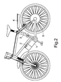
- FIG. 2 is an illustrative drawing showing how to dispose the component parts of the present invention on an electro mobile bike.
- FIG. 3 is a schematic view showing how the system of the present invention is applied to a hybrid power driven vehicle.
- FIG. 4 is a schematic view showing how the system of the present invention is applied to receive the power generated by a wind driven generator.
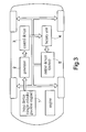
- FIG. 5 is an illustrative drawing showing how the incorporated power produced by a wind drive generator and a solar collector is supplied to an electro mobile (bike).
- FIG. 6 is a schematic view showing the layout of the component parts of the present invention.
- FIG. 7 is an illustrative drawing showing how the system of the present invention is applied to a hydrogen fuel cell.
- FIG. 8 is a schematic view showing control of the present invention.
- FIG. 9 is a schematic view showing how to distribute the energy produced by the present invention.
- FIG. 10 is a waveform diagram of the input device charging the battery unit.
- FIG. 11 is a waveform diagram of the battery unit discharging to the output device.
- the balanced energy and energy producing system of the present invention is essentially composed of an input device 1 connected to a driven generator 2 .
- a signal of the generator 2 is used to actuate a control device 3 , which has many stages (unlit grading) parameters and a battery monitoring parameter.
- the control device 3 supervises the generator 2 to supply the electric energy needed for a battery unit 4 and, based on the strength of the generator signal, drives an output device 5 up to a rated output value according to the many stages of parameters.
- the control device 3 is able to detect the drive capability of the output device 5 . If the output device 5 is a motor driven device, the control device 3 detects the revolution speed of the motor and, if the output device 5 is a domestic electric appliance, its current value will be detected.
- the input device 1 is a speed change device, and the input device 1 and generator 2 are equipped on an electro mobile bike.
- the power produced by manual pedaling action is inputted into the input device 1 to drive the generator 2 which in turn charges the battery unit 4 .
- the battery unit 4 then delivers its power to the output device 5 (motor) to drive the latter which in turn drives the electro mobile bike to run.
- the control device 3 plays the role of regulating the strength of current of the output device (motor) 5 according to many stages of parameters and, based on the signal strength of the generator 2 , so as to drive the output device (motor) 5 in a selective transmission manner until reaching a predetermined rated output speed.
- the control device 3 further detects the operating speed of the output device 5 and the signal strength of the generator 2 so as to make the control device 3 regulate the strength of the current output of the battery unit 4 to the output device 5 according to the many stages of parameters, thereby driving the output device (motor) 5 in a selective transmission manner.
- the output device (motor) 5 under operation indicates to the control device 3 to regulate its rotational speed with the many stages of parameters until the speed of the output device (motor) 5 reaches a predetermined rated value.
- the electro mobile bike driven as such does not require any chain, belt or transmission shaft.
- the generator 2 is driven by directly or indirectly producing manual pedaling power, whereby the signal of the generator 2 is sent to the control device 3 to drive the motor 5 , and the power of the battery unit 4 is supplied to the motor 5 . After running, the speed of the motor 5 is determined by the signal of the generator 2 and part of the running power of the motor 5 is fed back to the battery unit 4 .
- This primitive man-powered and operated electro mobile bike can therefore provide a low carbon footprint without losing its original effect.
- the system of the present invention is applied to a hybrid power driven vehicle.
- the input device 1 which is a 25 cc single cylinder gasoline engine, drives the generator 2 which in turn charges the battery unit 4 .
- the control device 3 equipped on the system supervises the output power of the battery unit 4 to drive the output device (motor) 5 , thereby enabling this hybrid power driven vehicle to run.
- the system of the present invention is applied to receive the power generated by a wind driven generator.
- the input device 1 which is a wind drive generator or a solar collector, supplies its produced electricity into the battery unit 4 through the control of the control device 3 .
- the produced electricity is then used to operate a domestic small size 3 C electronic product or a domestic electrical appliance.
- the output device 5 is a domestic electrical appliance, the signal strength of the generator 2 is able to let the control device 3 regulate the strength of current of the battery unit 4 supplying the output device (domestic appliance) 5 according to the many stages of parameters, thereby permitting the latter to operate with its rated output current.
- the electricity produced by the wind drive generator, the solar collector, and the electro mobile bike is stored in the battery unit 4 which, in turn, supplies the power to the output device 5 .
- the output device 5 is an electrolyzer 61 , which can perform an electrolyzing process in an electrolytic cell.
- the electrolytic cell further consists of a positive electrolyzer 61 and a negative electrode 62 immersed in a solution containing positive and negative ions.
- the positive and negative electrodes 61 , 62 are for producing oxygen and hydrogen.
- the control device 3 can further control the production process of oxygen and hydrogen and supply them to a hydrogen fuel cell 64 .
- the positive and negative electrodes 61 , 62 are connected to an oxygen fuel reservoir and a hydrogen fuel reservoir.
- the two reservoirs are respectively connected to a positive pole and a negative pole of the hydrogen fuel cell 64 so as to allow the cell 64 to output electricity continually.
- the hydrogen produced by the electrolyzer 61 can react with a catalyzer to transform its reaction energy into heat for use in room heating.
- the control device 3 controls the output current of the battery unit 4 and determines the output of the electrolyzer 61 .
- the utility factor of the hydrogen and the oxygen produced by the electrolyzer 61 can be determined.
- the heat energy produced by burning the catalyzer can also be controlled or maintain the temperature of the heat energy in a fixed range.
- FIG. 8 is a schematic view showing control of the present invention.
- FIG. 9 is a schematic view showing how to distribute the energy produced by the present invention.
- FIG. 10 is a waveform diagram of the input device 1 charging the battery unit 4 . This is the result of a simulation load test with a 200 w brushless DC motor, showing that the generator 2 is able to achieve a sufficient voltage and current at a relatively low speed to charge the battery unit 4 .
- FIG. 11 is a waveform diagram of the battery unit 4 discharging to the output device 5 .
- the present invention has several noteworthy advantages, in particular:
- Running distance of the electro-mobile bike at a time can be increased.
- Electric energy produced by wind power and solar collector(s) can be stored in a battery unit for domestic use, therefore serving as a low voltage power source for cellphones, computers, lighting, or the like.
- This energy producing system can provide electricity for rural areas which do not have electricity, serving as a power source for the modern small sized 3 C electronic product or the like.
Landscapes
- Engineering & Computer Science (AREA)
- Power Engineering (AREA)
- Mechanical Engineering (AREA)
- Life Sciences & Earth Sciences (AREA)
- Sustainable Development (AREA)
- Sustainable Energy (AREA)
- Transportation (AREA)
- Combustion & Propulsion (AREA)
- General Engineering & Computer Science (AREA)
- Chemical & Material Sciences (AREA)
- Charge And Discharge Circuits For Batteries Or The Like (AREA)
- Control Of Eletrric Generators (AREA)
- Electric Propulsion And Braking For Vehicles (AREA)
- Secondary Cells (AREA)
Abstract
A balanced energy and energy producing system is composed of an input device with a driven generator connected thereto. The signal of the generator actuates a controller having multiple grading parameters and battery monitoring parameters. The controller supervises the generator to supply the electrical energy needed for the battery and also, based on the strength of the generator signal, drives an output device up to a predetermined power rating according to the multiple grading parameters so as to establish an uprated power source management system applicable to hybrid power source electro mobiles, including bicycles, and domestic power generation thereby achieving efficient energy utilization.
Description
- 1. Field of the invention
- The present invention relates to a small sized, high power, low carbon emission generating system and, in particular, to a balanced energy and energy producing system.
- 2. Description of the Prior Art
- Environmental protection is one of the most important considerations of all global problems. This stimulated the rapid development of generating systems for bulk wind power, solar energy and tidal power. All of these installations require a large amount of investment. Rapid increase of the world population, concentration of the population to particular areas, and the need for natural resources have contributed to a severe problem of environmental contamination. Accordingly, authorities suggest the use of hybrid power vehicles as electro mobiles (bikes) for short distance transportation instead of depending on vehicles which consume petroleum-based oil fuel, so as to help alleviate environmental pollution.
- Incidentally, hybrid power vehicles are still very expensive for an ordinary consumer to use even though local government may grant a small subsidy as financial aid to encourage their use.
- However, due to continuously rising oil prices and growing environmental awareness, many people are now aware of the importance of saving energy in order to help our planet. For short distance transportation such as daily attendance at an office or school, or for going on an excursion at leisure, people realize that taking public transportation facilities and electro mobiles (bikes) are a clever choice for saving money instead of using the traditional petroleum consuming private vehicles.
- Present-day electro mobiles generally take 8 to 10 hours to recharge their battery to run about 50 km (30 km in case of bikes) at a time. Although this capability is enough for a short distance journey, a longer running time before needing to recharge the battery is preferable.
- It is the main object of the present invention to provide a balanced energy and energy producing system which can make use of hybrid power to develop a medium or small size high power generating system to supply power to electro bikes or domestic electrical appliances, or even to establish a medium or small size electric power plant using wind driven power or solar energy generation, so as to supply power for local domestic use and reduce carbon emissions
- To achieve the above object, the balanced energy and energy producing system provided by the present invention is composed of an input device with a driven generator connected thereto. The signal of the generator actuates a control device having many stages (multiple grading) of parameters and a battery monitoring parameter. The control device supervises the generator to supply the electrical energy needed for a battery unit and, based on the strength of the generator signal, drive an output device up to a predetermined power rating according to the many stages of parameters so as to establish an uprated power source management system applicable to a hybrid power source, electro mobiles including bikes, and domestic power generation, thereby achieving an efficient utilization of energy.
- The drawings disclose an illustrative embodiment of the present invention which serves to exemplify the various advantages and objects hereof, and are as follows:
-
FIG. 1 is an operation flow chart of the present invention. -
FIG. 2 is an illustrative drawing showing how to dispose the component parts of the present invention on an electro mobile bike. -
FIG. 3 is a schematic view showing how the system of the present invention is applied to a hybrid power driven vehicle. -
FIG. 4 is a schematic view showing how the system of the present invention is applied to receive the power generated by a wind driven generator. -
FIG. 5 is an illustrative drawing showing how the incorporated power produced by a wind drive generator and a solar collector is supplied to an electro mobile (bike). -
FIG. 6 is a schematic view showing the layout of the component parts of the present invention. -
FIG. 7 is an illustrative drawing showing how the system of the present invention is applied to a hydrogen fuel cell. -
FIG. 8 is a schematic view showing control of the present invention. -
FIG. 9 is a schematic view showing how to distribute the energy produced by the present invention. -
FIG. 10 is a waveform diagram of the input device charging the battery unit. -
FIG. 11 is a waveform diagram of the battery unit discharging to the output device. - Referring to
FIG. 1 , the balanced energy and energy producing system of the present invention is essentially composed of aninput device 1 connected to a drivengenerator 2. A signal of thegenerator 2 is used to actuate acontrol device 3, which has many stages (unlit grading) parameters and a battery monitoring parameter. Thecontrol device 3 supervises thegenerator 2 to supply the electric energy needed for abattery unit 4 and, based on the strength of the generator signal, drives anoutput device 5 up to a rated output value according to the many stages of parameters. Thecontrol device 3 is able to detect the drive capability of theoutput device 5. If theoutput device 5 is a motor driven device, thecontrol device 3 detects the revolution speed of the motor and, if theoutput device 5 is a domestic electric appliance, its current value will be detected. - Referring to
FIG. 2 , theinput device 1 is a speed change device, and theinput device 1 andgenerator 2 are equipped on an electro mobile bike. The power produced by manual pedaling action is inputted into theinput device 1 to drive thegenerator 2 which in turn charges thebattery unit 4. Thebattery unit 4 then delivers its power to the output device 5 (motor) to drive the latter which in turn drives the electro mobile bike to run. In the system, thecontrol device 3 plays the role of regulating the strength of current of the output device (motor) 5 according to many stages of parameters and, based on the signal strength of thegenerator 2, so as to drive the output device (motor) 5 in a selective transmission manner until reaching a predetermined rated output speed. Thecontrol device 3 further detects the operating speed of theoutput device 5 and the signal strength of thegenerator 2 so as to make thecontrol device 3 regulate the strength of the current output of thebattery unit 4 to theoutput device 5 according to the many stages of parameters, thereby driving the output device (motor) 5 in a selective transmission manner. The output device (motor) 5 under operation then indicates to thecontrol device 3 to regulate its rotational speed with the many stages of parameters until the speed of the output device (motor) 5 reaches a predetermined rated value. According to the present invention, the electro mobile bike driven as such does not require any chain, belt or transmission shaft. Instead, thegenerator 2 is driven by directly or indirectly producing manual pedaling power, whereby the signal of thegenerator 2 is sent to thecontrol device 3 to drive themotor 5, and the power of thebattery unit 4 is supplied to themotor 5. After running, the speed of themotor 5 is determined by the signal of thegenerator 2 and part of the running power of themotor 5 is fed back to thebattery unit 4. This primitive man-powered and operated electro mobile bike can therefore provide a low carbon footprint without losing its original effect. - Referring to
FIG. 3 , the system of the present invention is applied to a hybrid power driven vehicle. Theinput device 1, which is a 25 cc single cylinder gasoline engine, drives thegenerator 2 which in turn charges thebattery unit 4. Thecontrol device 3 equipped on the system supervises the output power of thebattery unit 4 to drive the output device (motor) 5, thereby enabling this hybrid power driven vehicle to run. - Referring to
FIG. 4 , the system of the present invention is applied to receive the power generated by a wind driven generator. Theinput device 1, which is a wind drive generator or a solar collector, supplies its produced electricity into thebattery unit 4 through the control of thecontrol device 3. The produced electricity is then used to operate a domestic small size 3C electronic product or a domestic electrical appliance. If theoutput device 5 is a domestic electrical appliance, the signal strength of thegenerator 2 is able to let thecontrol device 3 regulate the strength of current of thebattery unit 4 supplying the output device (domestic appliance) 5 according to the many stages of parameters, thereby permitting the latter to operate with its rated output current. - Referring to
FIG. 5 andFIG. 6 , the electricity produced by the wind drive generator, the solar collector, and the electro mobile bike is stored in thebattery unit 4 which, in turn, supplies the power to theoutput device 5. In this system, theoutput device 5 is anelectrolyzer 61, which can perform an electrolyzing process in an electrolytic cell. The electrolytic cell further consists of apositive electrolyzer 61 and anegative electrode 62 immersed in a solution containing positive and negative ions. The positive andnegative electrodes - Referring to
FIG. 7 , thecontrol device 3 can further control the production process of oxygen and hydrogen and supply them to ahydrogen fuel cell 64. The positive andnegative electrodes hydrogen fuel cell 64 so as to allow thecell 64 to output electricity continually. - Returning to
FIG. 5 , in addition to supplying thehydrogen fuel cell 64, the hydrogen produced by theelectrolyzer 61 can react with a catalyzer to transform its reaction energy into heat for use in room heating. In the energy producing system of the present invention, thecontrol device 3 controls the output current of thebattery unit 4 and determines the output of theelectrolyzer 61. Moreover, the utility factor of the hydrogen and the oxygen produced by theelectrolyzer 61 can be determined. Similarly the heat energy produced by burning the catalyzer can also be controlled or maintain the temperature of the heat energy in a fixed range. -
FIG. 8 is a schematic view showing control of the present invention.FIG. 9 is a schematic view showing how to distribute the energy produced by the present invention.FIG. 10 is a waveform diagram of theinput device 1 charging thebattery unit 4. This is the result of a simulation load test with a 200 w brushless DC motor, showing that thegenerator 2 is able to achieve a sufficient voltage and current at a relatively low speed to charge thebattery unit 4.FIG. 11 is a waveform diagram of thebattery unit 4 discharging to theoutput device 5. - The present invention has several noteworthy advantages, in particular:
- 1. Running distance of the electro-mobile bike at a time can be increased.
- 2. Electric energy produced by wind power and solar collector(s) can be stored in a battery unit for domestic use, therefore serving as a low voltage power source for cellphones, computers, lighting, or the like.
- 3. This energy producing system can provide electricity for rural areas which do not have electricity, serving as a power source for the modern small sized 3C electronic product or the like.
- As for the outstanding functional effects of the present invention, it should be pointed out that:
- 1. It can control and supervise the generator and the output device intelligently.
- 2. It can automatically regulate and figure out the output/input capacity of the battery unit.
- 3. It can control the battery unit and the output device to output power smoothly.
- 4. It can securely control, figure out, and supervise the energy stored in the battery unit.
- Many changes and modifications in the above described embodiment of the invention can, of course, be carried out without departing from the scope thereof. Accordingly, to promote the progress in science and the useful arts, the invention is disclosed and is intended to be limited only by the scope of the appended claims.
Claims (6)
1. A balanced energy and energy producing system comprising:
an input device with a driven generator connected thereto; and
a control device having many stages of parameters and a battery monitoring parameter to be actuated by a signal of said driven generator,
wherein said control device supervises said generator to supply the electric energy needed for a battery unit and, based on the strength of said generator signal, drives an output device up to a predetermined power rating according to said many stages of parameters.
2. The system of claim 1 , wherein said output device is a motor, the signal strength of said generator makes said control device to-regulate the strength of current of said battery unit supplied to said output device according to said many stages of parameters, so as to operate said output device in a selected transmission manner to reach a predetermined rated output speed value.
3. The system of claim 1 , wherein said output device is a motor, said control device is further able to detect the revolution of said output device, the strength of said generator signal makes said control device regulate the strength of current of said battery unit supplied to said output device according to said many stages of parameters, so as to drive said output device in a selected transmission manner, said output device under operation indicates its revolution speed, and said control device regulates the revolution of said output device according to said many stages of parameters, thereby making the revolution of said output device reach the predetermined rated value.
4. The system of claim 1 , wherein said output device is a domestic electric appliance, the strength of said generator signal makes said control device regulate the strength of current of said battery unit supplied to said output device according to said many stages of parameters, and said control device regulates the electricity produced by said output device with said many stages of parameters to reach the predetermined rated output current value.
5. The system of claim 1 , wherein said output device is an electrolyzer which can perform an electrolyzing process in an electrolytic cell, said electrolytic cell further consists of a positive electrode and a negative electrode immersed in a solution containing positive and negative ions, wherein said positive and said negative electrodes are for producing oxygen and hydrogen, respectively.
6. The system of claim 5 , wherein said positive and said negative electrodes are connected to an oxygen fuel reservoir and a hydrogen fuel reservoir, and said two reservoirs are respectively connected to a positive pole and a negative pole of said hydrogen fuel cell so as to allow said hydrogen fuel cell to output electricity continually.
Applications Claiming Priority (2)
| Application Number | Priority Date | Filing Date | Title |
|---|---|---|---|
| CNPCT/CN2011/072345 | 2011-03-31 | ||
| PCT/CN2011/072345 WO2012129809A1 (en) | 2011-03-31 | 2011-03-31 | Energy management and energy production system |
Publications (1)
| Publication Number | Publication Date |
|---|---|
| US20120249081A1 true US20120249081A1 (en) | 2012-10-04 |
Family
ID=46926332
Family Applications (1)
| Application Number | Title | Priority Date | Filing Date |
|---|---|---|---|
| US13/435,516 Abandoned US20120249081A1 (en) | 2011-03-31 | 2012-03-30 | Balanced energy and energy producing system |
Country Status (3)
| Country | Link |
|---|---|
| US (1) | US20120249081A1 (en) |
| CN (1) | CN103283114B (en) |
| WO (1) | WO2012129809A1 (en) |
Cited By (2)
| Publication number | Priority date | Publication date | Assignee | Title |
|---|---|---|---|---|
| US20090266397A1 (en) * | 2008-04-23 | 2009-10-29 | Gm Global Technology Operations, Inc. | Solar battery charging system and optional solar hydrogen production system for vehicle propulsion |
| EP2907215A4 (en) * | 2012-10-11 | 2016-07-06 | Windstrip Llc | MULTIPLE INPUT HYBRID POWER SYSTEM AND SINGLE OUTPUT |
Families Citing this family (2)
| Publication number | Priority date | Publication date | Assignee | Title |
|---|---|---|---|---|
| DE102016124491A1 (en) * | 2015-12-16 | 2017-06-22 | Red Automotive Technologies Pty Ltd | Home and motor vehicle energy system |
| CN112879254B (en) * | 2021-03-15 | 2023-05-30 | 许昌学院 | Household combined new energy power generation energy-saving device |
Citations (7)
| Publication number | Priority date | Publication date | Assignee | Title |
|---|---|---|---|---|
| US6109770A (en) * | 1995-12-21 | 2000-08-29 | Kim Charles | Illuminating or light signalling device, particularly for bicycles and the like |
| US6555928B1 (en) * | 1999-09-21 | 2003-04-29 | Yamaha Hatsudoki Kabushiki Kaisha | Power source control method for an electric vehicle |
| US20080121452A1 (en) * | 2006-09-22 | 2008-05-29 | Dan Bon | Propelled bicycle with automatic transmission |
| US7706935B2 (en) * | 2004-09-14 | 2010-04-27 | Systemes D'energie Et Propulsion Eps Inc. | Energy management system for motor-assisted user-propelled vehicles |
| US20110001442A1 (en) * | 2009-07-02 | 2011-01-06 | Chong Uk Lee | Electric bicycle drive system with regenerative charging |
| US20110048830A1 (en) * | 2002-12-03 | 2011-03-03 | Jeffrey L. Radtke | Self-propelled wheel for bicycles and similar vehicles |
| US20120012412A1 (en) * | 2009-02-12 | 2012-01-19 | Frank Moeller | Bicycle Transmission System |
Family Cites Families (7)
| Publication number | Priority date | Publication date | Assignee | Title |
|---|---|---|---|---|
| US6230496B1 (en) * | 2000-06-20 | 2001-05-15 | Lockheed Martin Control Systems | Energy management system for hybrid electric vehicles |
| JP2002187584A (en) * | 2000-12-22 | 2002-07-02 | Shimano Inc | Drive control circuit for electric bicycle unit |
| NL1018569C2 (en) * | 2001-07-17 | 2003-01-23 | Ceap B V | Mobile power plant. |
| JP2003259508A (en) * | 2002-02-26 | 2003-09-12 | Sanyo Electric Co Ltd | Power supply for electric vehicles |
| KR101070906B1 (en) * | 2004-10-01 | 2011-10-06 | 설승기 | Distributed power generation system and control method for the same |
| JP2006325372A (en) * | 2005-05-20 | 2006-11-30 | Shimano Inc | Dc power supply unit for human-powered vehicle |
| CN1776223A (en) * | 2005-11-23 | 2006-05-24 | 王登祥 | Wind power generation method and equipment thereof |
-
2011
- 2011-03-31 WO PCT/CN2011/072345 patent/WO2012129809A1/en not_active Ceased
- 2011-03-31 CN CN201180063381.2A patent/CN103283114B/en not_active Expired - Fee Related
-
2012
- 2012-03-30 US US13/435,516 patent/US20120249081A1/en not_active Abandoned
Patent Citations (7)
| Publication number | Priority date | Publication date | Assignee | Title |
|---|---|---|---|---|
| US6109770A (en) * | 1995-12-21 | 2000-08-29 | Kim Charles | Illuminating or light signalling device, particularly for bicycles and the like |
| US6555928B1 (en) * | 1999-09-21 | 2003-04-29 | Yamaha Hatsudoki Kabushiki Kaisha | Power source control method for an electric vehicle |
| US20110048830A1 (en) * | 2002-12-03 | 2011-03-03 | Jeffrey L. Radtke | Self-propelled wheel for bicycles and similar vehicles |
| US7706935B2 (en) * | 2004-09-14 | 2010-04-27 | Systemes D'energie Et Propulsion Eps Inc. | Energy management system for motor-assisted user-propelled vehicles |
| US20080121452A1 (en) * | 2006-09-22 | 2008-05-29 | Dan Bon | Propelled bicycle with automatic transmission |
| US20120012412A1 (en) * | 2009-02-12 | 2012-01-19 | Frank Moeller | Bicycle Transmission System |
| US20110001442A1 (en) * | 2009-07-02 | 2011-01-06 | Chong Uk Lee | Electric bicycle drive system with regenerative charging |
Cited By (3)
| Publication number | Priority date | Publication date | Assignee | Title |
|---|---|---|---|---|
| US20090266397A1 (en) * | 2008-04-23 | 2009-10-29 | Gm Global Technology Operations, Inc. | Solar battery charging system and optional solar hydrogen production system for vehicle propulsion |
| EP2907215A4 (en) * | 2012-10-11 | 2016-07-06 | Windstrip Llc | MULTIPLE INPUT HYBRID POWER SYSTEM AND SINGLE OUTPUT |
| US9979199B2 (en) | 2012-10-11 | 2018-05-22 | Windstrip Llc | Multiple input single output hybrid power system |
Also Published As
| Publication number | Publication date |
|---|---|
| WO2012129809A1 (en) | 2012-10-04 |
| CN103283114B (en) | 2016-10-26 |
| CN103283114A (en) | 2013-09-04 |
Similar Documents
| Publication | Publication Date | Title |
|---|---|---|
| Hannan et al. | Hybrid electric vehicles and their challenges: A review | |
| CN205395796U (en) | Automatic switched systems of electric automobile double cell | |
| US8109354B2 (en) | Oxyhydrogen vehicle | |
| CN114094644B (en) | Optical storage, charging and replacement integrated micro-grid system | |
| CN202737555U (en) | Composite energy device for ships and ship equipped with composite energy device | |
| US20120249081A1 (en) | Balanced energy and energy producing system | |
| CN105720283A (en) | Fuel cell hybrid power system and working method thereof | |
| CN202063028U (en) | Power device of electric automobile | |
| CN202260597U (en) | Wind power, light energy and diesel oil complementary power generation system | |
| CN102570905B (en) | Vehicle power supply system using solar energy and vehicle power supply control method | |
| Yan et al. | Simulation and optimization of hybrid wind-solar-pumped-storage power system | |
| CN202309237U (en) | Combined energy acquisition, integration, storage and application system | |
| TWI443932B (en) | Balanced energy and energy production systems | |
| CN205429868U (en) | A power supply conversion system for an oxygen hydrogen machine | |
| Premalatha et al. | Design of EV charging station using renewable energy sources | |
| CN202670086U (en) | New energy electric boat | |
| CN201934216U (en) | Automobile fuel saving and emission reducing device | |
| CN204810195U (en) | Big sun can three complementary circulation power generation facility of power generation system intelligence of wind energy and high -efficient permanent magnet generator | |
| CN206135469U (en) | Battery swapping station that fills who contains honourable complementary power | |
| Prakash et al. | Hybrid Electric Vehicles with Multiple Charging System | |
| CN203151194U (en) | A low-voltage storage battery charging device of a serial-parallel hybrid electric vehicle | |
| US20110204735A1 (en) | Electric cycling dynamic system | |
| Nayak et al. | Evaluation of Solar-Powered Bicycles to Promote an Eco-Friendly Environment | |
| CN113541443A (en) | Novel permanent magnet power generator for energy pure electric vehicle | |
| CN201446875U (en) | Double-energy electric vehicle driving system |
Legal Events
| Date | Code | Title | Description |
|---|---|---|---|
| STCB | Information on status: application discontinuation |
Free format text: ABANDONED -- FAILURE TO RESPOND TO AN OFFICE ACTION |