US20120216632A1 - Liquid sample analyzing apparatus and liquid sample introducing apparatus - Google Patents
Liquid sample analyzing apparatus and liquid sample introducing apparatus Download PDFInfo
- Publication number
- US20120216632A1 US20120216632A1 US13/503,694 US201013503694A US2012216632A1 US 20120216632 A1 US20120216632 A1 US 20120216632A1 US 201013503694 A US201013503694 A US 201013503694A US 2012216632 A1 US2012216632 A1 US 2012216632A1
- Authority
- US
- United States
- Prior art keywords
- sample
- needle
- washing
- flow passage
- washing solution
- Prior art date
- Legal status (The legal status is an assumption and is not a legal conclusion. Google has not performed a legal analysis and makes no representation as to the accuracy of the status listed.)
- Granted
Links
Images


Classifications
-
- G—PHYSICS
- G01—MEASURING; TESTING
- G01N—INVESTIGATING OR ANALYSING MATERIALS BY DETERMINING THEIR CHEMICAL OR PHYSICAL PROPERTIES
- G01N30/00—Investigating or analysing materials by separation into components using adsorption, absorption or similar phenomena or using ion-exchange, e.g. chromatography or field flow fractionation
- G01N30/02—Column chromatography
- G01N30/04—Preparation or injection of sample to be analysed
- G01N30/16—Injection
- G01N30/20—Injection using a sampling valve
-
- G—PHYSICS
- G01—MEASURING; TESTING
- G01N—INVESTIGATING OR ANALYSING MATERIALS BY DETERMINING THEIR CHEMICAL OR PHYSICAL PROPERTIES
- G01N30/00—Investigating or analysing materials by separation into components using adsorption, absorption or similar phenomena or using ion-exchange, e.g. chromatography or field flow fractionation
- G01N30/02—Column chromatography
- G01N30/04—Preparation or injection of sample to be analysed
- G01N30/24—Automatic injection systems
-
- G—PHYSICS
- G01—MEASURING; TESTING
- G01N—INVESTIGATING OR ANALYSING MATERIALS BY DETERMINING THEIR CHEMICAL OR PHYSICAL PROPERTIES
- G01N30/00—Investigating or analysing materials by separation into components using adsorption, absorption or similar phenomena or using ion-exchange, e.g. chromatography or field flow fractionation
- G01N30/02—Column chromatography
- G01N30/04—Preparation or injection of sample to be analysed
- G01N30/16—Injection
- G01N30/20—Injection using a sampling valve
- G01N2030/207—Injection using a sampling valve with metering cavity, e.g. sample loop
Definitions
- This invention relates to a liquid sample analyzing apparatus and liquid sample introducing apparatus.
- a mobile phase is sucked into the apparatus by a pump unit, being fed to a separation column with a sample introduced by an automatic sample introduction unit.
- the sample introduced in the separation column is separated into components to be detected by various kinds of detectors.
- HPLC high performance liquid chromatography
- an analysis operation is required to be operated under high pressure flow passage at 20 to 40 M Pa at its maximum.
- a pump unit used for HPLC as described above, it is required that a mobile phase can be supplied to the apparatus correctly and precisely even under high pressure condition.
- the automatic sample introducing unit is used as an apparatus which sucks the sample liquid by using a needle from a sample holding container lined up on sample rack, thereafter, the apparatus stores the sample in a sample storage loop to discharge the sample into a mobile phase flow passage of the liquid chromatography automatically. Furthermore, there are automatic sample introduction units having a pre-processing function for diluting a sample before discharging into mobile phase flow passage and for mixing the sample and reaction reagent for labeling, or the like.
- the injection system in the above automatic sample introduction apparatus is generally divided into two kinds.
- one kind of an injection system which is a direct injection system (refer to the patent document 1 and the patent document 2), a needle and a sample storage loop are integrated into a mobile phase flow passage under high pressure condition.
- a needle and a sample storage loop are integrated into a mobile phase flow passage under high pressure condition.
- a loop injection system (refer to the patent document 3) only a needle is integrated into a mobile phase flow passage under high pressure condition.
- a sample temporarily stored in the needle and the sample storage loop is pushed out toward the column by the mobile phase at the start of analysis, and the mobile phase is always flushed in the needle and the sample storage loop during the analysis operation, so that the sucked sample can be introduced into the column without waste of the sample, and the is no need for installing other unit for washing the inner of the needle contaminated by the sample. It is the merit of the direct injection system.
- the direct injection system is not suitable for handling of diluting and mixing the sample in the pre-process. It is the demerit of the direct injection system.
- the loop injection system since the needle is positioned outside of the mobile phase flow passage under high pressure condition during the analysis operation, the movement of the needle and the sample accounting operation can be executed during the analysis operation. Accordingly, a construction is not required for keeping the high pressure between the needle and the sample injection port, so that the pre-process of the sample can be executed during the analysis operation. It is the merit of the loop injection system.
- the loop injection system requires an equipment and process for washing the inner of the needle, so that the loop injection system may require long time for injecting a sample in comparison with the direct injection system. It is the demerit of the loop injection system.
- UHPLC ultra high performance liquid chromatography
- the basic item of an automatic sample introducing unit required for the UHPLC is to have high injection quantity repeatability, low carry over, high speed process (reducing of cycle time), high reliability, and high durability against multiple samples analysis request under ultra high pressure of 60 to 120 M Pa at its maximum.
- a sample introduction apparatus employing the direct injection system has a mechanism which can always keep the fluid-tight between the needle and the seal in the sample injection port in order to avoid the ejection of the mobile phase form the sample inlet port even under high pressure condition.
- the needle integrated in the high pressure flow passage and the sample storage loop are separated from the high pressure flow passage by the flow passage exchange valve at the sample suction step, the needle and the solvent in the sample storage loop being exposed under the atmospheric pressure.
- the needle is inserted into the sample hold container, and the sample is sucked into the needle or sample storage loop, thereafter, the needle is moved at the above-mentioned sample injection port.
- the flow passage exchange valve is switched again, the sample with the mobile phase fed by the pump units are supplied to the column.
- the automatic sample introduction unit of the loop injection system is suitable for the UHPLC.
- the operation stroke number of the syringe per number of the analyses is numerous.
- the consumable syringe exchange frequency is extremely high, so that the reliability and durability of the apparatus is deteriorated.
- the high accuracy and high discrimination operation of the syringe is required at low flow rate (low speed) for sample accounting operation, and the high flow rate (high speed) operation of the syringe is required for the flow passage washing operation in order to reduce the washing time.
- the above-mentioned two requirements are conflict with each other, so that there is limit vale to satisfy the two requirements by using the operation of one syringe. Namely, when a small volume syringe is used for prior to sample quantity accounting, the washing time grows longer and the cycle time grows longer. The problem is happened. On the other hand, when a large volume syringe is used for prior to flow passage washing, the accuracy and discrimination of the operation of the syringe are deteriorated. As the result, the injection rate repeatability is lowered.
- washing system of the external wall of the needle is the dipping washing system only, the sample attached to the external wall of the needle cannot be washed fully. Therefore, it is one factor of carry-over of a sample.
- An object of the present invention is to realize a liquid sample analyzing apparatus and a liquid sample introduction apparatus capable for processing a sample with high reliability at high speed.
- the present invention is constructed as follows:
- a liquid sample analyzing apparatus a liquid sample introduction apparatus, and a liquid sample introducing system
- an external wall of a needle sucking and discharging a liquid sample is inserted into a washing tank to wash the external wall
- a liquid sample being sucked into the needle while the quantity of the liquid sample is accounted by using a syringe
- the liquid sample sucked into the needle being supplied to a sample storage loop while the liquid sample sucked into the needle is accounted by using the syringe
- the liquid sample stored in the sample storage loop being supplied to a mobile phase flow passage
- the needle being separated from the syringe means
- a washing solution being supplied from the washing solution supply means into the needle to wash the inner wall of the needle.
- the present invention can realize a liquid sample analyzing apparatus, a liquid sample introduction apparatus, and a liquid sample introduction system capable for processing a sample with high reliability at high speed.
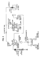
- FIG. 1 is a drawing showing a schematic construction and an idling condition of a liquid chromatograph apparatus according to the first embodiment of the present invention
- FIG. 2 is a drawing showing a schematic construction and a step for a washing solution suction of a syringe and for washing an external wall of a needle of the liquid chromatograph apparatus according to the first embodiment of the present invention
- FIG. 3 is a drawing showing a schematic construction and a sample suction step of the liquid chromatograph apparatus according to the first embodiment of the present invention
- FIG. 4 is a drawing showing a schematic construction and a step for washing the external wall of a needle of the liquid chromatograph apparatus according to the first embodiment of the present invention
- FIG. 5 is a drawing showing a schematic construction and a step for discharging a lead volume from the needle of the liquid chromatograph apparatus according to the first embodiment of the present invention
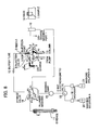
- FIG. 6 is a drawing showing a schematic construction and a step for separating a sample storage loop from a mobile phase flow passage to decreasing the pressure of the liquid chromatograph apparatus according to the first embodiment of the present invention
- FIG. 7 is a drawing showing a schematic construction and a step for feeding a sample to a sample storage loop of the liquid chromatograph apparatus according to the first embodiment of the present invention
- FIG. 8 is a drawing showing a schematic construction and a step for feeding a sample in a mobile phase flow passage a sample storage from the sample storage loop of the liquid chromatograph apparatus according to the first embodiment of the present invention
- FIG. 9 is a drawing showing a schematic construction and a step for washing the inner wall of the needle of the first embodiment of the present invention.
- FIG. 10 is a drawing showing a schematic construction and a step for washing the inner wall of the needle of the first embodiment of the present invention.
- FIG. 11 is a drawing showing a schematic construction and a step for washing a plunger of the liquid chromatograph apparatus according to the first embodiment of the present invention
- FIG. 12 is a drawing showing a schematic construction and a step for sucking the washing solution of the syringe and for washing the external wall of the needle of the liquid chromatograph apparatus according to the second embodiment of the present invention
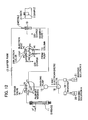
- FIG. 13 is a drawing showing a schematic construction and a step for sucking a sample of the liquid chromatograph apparatus according to the second embodiment of the present invention.
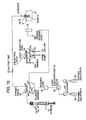
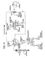
- FIG. 14 is a drawing showing a schematic construction and a step for washing the external wall of a needle of the liquid chromatograph apparatus according to the second embodiment of the present invention.
- FIG. 15 is a drawing showing a schematic construction and a step for moving the needle for the sample injection port of the liquid chromatograph apparatus according to the second embodiment of the present invention.
- FIG. 16 is a drawing showing a schematic construction and a step for separating the sample storage loop from the mobile phase flow passage and for decreasing the pressure of the sample storage loop of the liquid chromatograph apparatus according to the second embodiment of the present invention
- FIG. 17 is a drawing showing a schematic construction and a step for feeding the sample to the sample storage loop of the liquid chromatograph apparatus according to the second embodiment of the present invention.
- FIG. 18 is a drawing showing a schematic construction and a step for feeding the sample into the mobile phase flow passage from the sample storage loop of the second embodiment of the present invention.
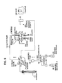
- FIG. 19 is a drawing showing a schematic construction and a step for sucking the washing solution of the syringe and for washing the external wall of the needle of the liquid chromatograph apparatus according to the third embodiment of the present invention.
- FIG. 20 is a drawing showing a schematic construction and a step for sucking the sample of the liquid chromatograph apparatus according to the third embodiment of the present invention.
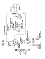
- FIG. 21 is a drawing showing a schematic construction and a step for washing the external wall of the needle of the liquid chromatograph apparatus according to the third embodiment of the present invention.
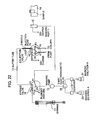
- FIG. 22 is a drawing showing a schematic construction and a step for moving the needle for the sample injection port of the liquid chromatograph apparatus according to the third embodiment of the present invention.
- FIG. 23 is a drawing showing a schematic construction and a step for separating the sample storage loop from the mobile phase flow passage and for decreasing the pressure of the sample storage loop of the liquid chromatograph apparatus according to the third embodiment of the present invention
- FIG. 24 is a drawing showing a schematic construction and a step for feeding the sample for the sample storage loop of the third embodiment of the present invention.
- FIG. 25 is a drawing showing a schematic construction and a step for feeding the sample into the mobile phase flow passage from the sample storage loop of the liquid chromatograph apparatus according to the third embodiment of the present invention.
- FIG. 26 is a drawing showing a schematic construction the liquid chromatograph apparatus according to the fourth embodiment of the present invention.
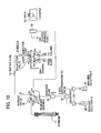
- FIG. 27 is a drawing showing a schematic construction and an idling condition of a liquid chromatograph apparatus according to the fifth embodiment of the present invention.
- FIG. 28 is a drawing showing a schematic construction and a step for sucking the washing solution of the syringe of a liquid chromatograph apparatus according to the fifth embodiment of the present invention.
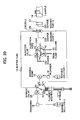
- FIG. 29 is a drawing showing a schematic construction and a step for sucking the sample of a liquid chromatograph apparatus according to the fifth embodiment of the present invention.
- FIG. 30 is a drawing showing a schematic construction and a step for washing the external wall of the needle of a liquid chromatograph apparatus according to the fifth embodiment of the present invention.
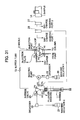
- FIG. 31 is a drawing showing a schematic construction and a step for moving the needle for the sample injection port of a liquid chromatograph apparatus according to the fifth embodiment of the present invention.
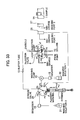
- FIG. 32 is a drawing showing a schematic construction and a step for separating the sample storage loop from the mobile flow passage and for decreasing the pressure in the sample storage loop of a liquid chromatograph apparatus according to the fifth embodiment of the present invention
- FIG. 33 is a drawing showing a schematic construction and a step for feeding the sample to the sample storage loop of a liquid chromatograph apparatus according to the fifth embodiment of the present invention.
- FIG. 34 is a drawing showing a schematic construction and a step for feeding the sample to the mobile phase flow passage from the sample storage loop of a liquid chromatograph apparatus according to the fifth embodiment of the present invention.
- FIG. 35 is a drawing showing a schematic construction and a step for washing the inner wall of the needle of a liquid chromatograph apparatus according to the fifth embodiment of the present invention.
- FIG. 36 is a drawing showing a schematic construction and a step for washing the inner wall of the needle of a liquid chromatograph apparatus according to the fifth embodiment of the present invention.
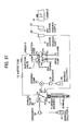
- FIG. 37 is a drawing showing a schematic construction and a step for washing the inner wall of the needle of a liquid chromatograph apparatus according to the fifth embodiment of the present invention.
- FIG. 38 is a drawing showing a schematic construction and an idling condition of a liquid chromatograph apparatus according to the fifth embodiment of the present invention.
- FIG. 39 is a drawing showing a schematic construction and a step for washing the plunger of the pump unit of a liquid chromatograph apparatus according to the fifth embodiment of the present invention.
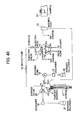
- FIG. 40 is a drawing showing a schematic construction and a step for washing the plunger of the pump unit of a liquid chromatograph apparatus according to the fifth embodiment of the present invention.
- FIG. 41 is a drawing showing a schematic construction and a step for washing the external wall of the needle of a liquid chromatograph apparatus according to the fifth embodiment of the present invention.
- FIG. 42 is a drawing showing a schematic construction and a step for washing the external wall of the needle of a liquid chromatograph apparatus according to the fifth embodiment of the present invention.
- FIG. 43 is an operation control function block diagram of each of the first to fifth embodiments of the present invention.
- FIG. 44 shows an example of a sample introducing apparatus which is different from the present invention in order to compare with the present invention.
- FIG. 1 is a showing a schematic construction of a liquid chromatograph apparatus using a loop injection system automatic sample introduction apparatus of the first embodiment of the present invention
- FIGS. 2 to 11 being diagrams showing the details of a sample injection step of the first embodiment of the present invention.
- FIG. 43 is an operation control block diagram of the embodiment of the present invention.
- a sample hold container 1 is set on a sample rack 14 .
- a needle 2 is moved between the sample hold container 1 , a washing tank 10 , and a sample injection port 3 of the 6-port 2-position valve (a first flow passage exchange means) 8 by a needle moving mechanism 51 .
- the needle moving mechanism 51 is controlled by an operation control unit 50 .
- a port P 1 is connected to a pump unit 7 , a port P 2 being connected to a separation column 6 , a port P 4 being connected to the sample injection port 3 , a port P 5 being connected to a drain 22 , a sample storage loop 5 being connected between a port P 3 and P 6 .
- the separation column 6 is connected to a detector 30 .
- the detector 30 detects and analyses a sample supplied from the separation column 6 .
- the 6-port 2-position valve 8 can be set to two positions of an injection position communicating the ports P 1 -P 6 , P 4 -P 5 , and P 2 -P 3 and a load position communicating the ports P 1 -P 2 , P 3 -P 4 , and P 5 -P 6 by rotating the valve at 60 degrees.
- a washing unit (a washing pump (a washing solution feeding means)) 15 is connected to a three way valve 18 , the three way valve 18 being connected to a washing bottle 20 and a washing bottle 21 through a degassing unit (degasser) 19 .
- the washing unit 15 can select one of a washing solutions A or a washing solution B to be fed to a 5-port 4-position valve (a second flow passage exchanging means) 16 by exchanging the three way valve 18 into the washing solution bottle 20 side or the washing solution bottle 21 side.
- the port P 1 is connected to the washing tank 10 through a washing solution pipe 31 , the port P 2 being connected to a buffer pipe 13 , the port P 3 being connected to a syringe 11 which is a sample accounting means, the port P 4 being connected to a plunger washing flow passage 17 , the common port P 5 being connected to the washing unit 15 .
- the plunger washing flow passage 17 communicates the pump unit 7 , washing salt, which is included in the mobile phase, deposited on the surface of the plunger of the pump unit 7 from the automatic sample introduction apparatus at need.
- the 5-port 4-position valve 16 can be set to four positions of (1) communicating the ports P 1 -P 5 and P 2 -P 3 , (2) communicating the ports P 2 -P 5 and P 3 -P 4 , (3) communicating the ports P 3 -P 5 and (4) communicating the ports P 4 -P 5 by rotating the valve at 45 degrees at each of positions.
- the needle 2 When the 5-port 4-position valve 16 is set to the position (1) that the port P 1 -P 5 and the port P 2 -P 3 are communicated with each other, the needle 2 is connected to the syringe 11 , which is the accounting means, through the buffer pipe 13 , and the needle 2 sucks and discharges a liquid by operating the syringe 11 up and down.
- the movement, suction and injection operation of the syringe 11 are controlled by a syringe moving mechanism 52 , the washing unit 15 being operated by a washing unit operation mechanism 53 . Further, the syringe valve 16 is operated by a syringe valve operation mechanism 54 , the three way valve 18 being operated by a three way valve operation mechanism 55 , the two position valve 8 being operated by a two position operation valve mechanism 56 .
- the liquid chromatograph apparatus as shown in FIG. 1 constructs a sample introduction apparatus used for the liquid chromatograph apparatus, except for the pump unit 7 , the separation column 6 , and the detector 30 .
- the sample introduction apparatus used for the liquid chromatograph apparatus includes the syringe 11 , the valve 16 , the washing unit 15 , the three way valve 18 , the degasser 19 , the buffer pipe 13 , the needle 2 , the injection valve 8 , the washing tank 10 , and the washing solution tank 31 .
- the needle 2 sucks the sample whose quantities are large volume in comparison with the actual volume to be discharged into the mobile phase flow passage, the front edge portion and the rear end portion of the corresponding to the washing solution part in the sucked sample being cut, only the center portion of the sucked sample being fed to the column.
- This system is so called a cut type system. The detailed description of each step of the cut type system will be described herein under, and the agreement of the definitions of terms will be described as follows:
- vi injection volume (net sample introduction volume to the mobile phase flow passage), vl: lead volume (cut volume), vr: rear volume (cut volume), vd: dead volume from the sample injection port to the injection valve, va: air volume (volume of the air layer in front and rear of a sample).
- the air volume va is arranged in front of the sample and the rear of the sample.
- FIG. 1 is a drawing to show the flow passage of the idle condition after the initializing operation of the automatic sample introduction apparatus.
- the mobile phase flows into the separation column 6 from the pump unit 7 through the sample storage loop 5 of the 6-port 2-position valve 8 .
- the washing solution bottle 20 is connected to the syringe 11 through the three way valve 18 , the washing unit 15 , and the port 3 of the 5-port 4-position valve 16 .
- the needle 2 is positioned above the washing tank 10 (the needle 2 is opposite to the opening portion of the washing tank 10 ).
- FIG. 2 is a drawing to show the step for sucking the washing solution A from the washing solution bottle A 20 and the step for washing the external wall of the needle 2 in the washing tank 10 .
- the syringe 11 sucks the dead volume vd of the washing solution A.
- the 5-port 4-position valve 16 is rotated at 90 degrees in the clockwise direction to exchange the position into communicating position of (1) the ports P 1 -P 5 and P 2 -P 3 , so that the needle is connected to the syringe 11 through the buffer pipe 13 .
- the needle 2 is moved into the washing tank 10 , the washing solution A being fed to the washing tank 10 by the washing unit 15 to wash the external wall of the needle 2 (washing operation prior to the sample suction operation).
- FIG. 3 is a drawing to show the sample sucking step.
- the syringe 11 sucks the air in volume of the half of the air volume va/2 during the operation of moving the needle for the sample hold container 1 .
- FIG. 4 is a drawing to show the flow passage at the step for washing the external wall of the needle 2 in the washing tank 10 by means of the washing solution A.
- the syringe 11 sucks the half volume va/2 of the air volume during the operation for moving the needle 2 into the washing tank 10 .
- the washing unit 15 feeds the washing solution A to the washing tank 10 to wash the external wall of the needle 2 (washing after the sample sucking operation).
- FIG. 5 is a drawing to show the flow passage at the step for moving the needle 2 to the sample injection port 3 (the port P 4 ) of the injection valve 8 and for discharging the lead volume of the sample.
- the needle 2 is moved to the sample injection port 3 .
- FIG. 6 is a drawing to show the flow passage at the pressure decreasing step for separating the sample storage loop 5 of the injection valve 8 from the mobile phase flow passage.
- the 6-port 2-position valve 8 is rotated at 60 degrees in counterclockwise direction, so that the sample storage loop 5 under high pressure condition is separated from the mobile phase flow passage, and the pressure loaded to the solvent in the sample storage loop 5 is released at the atmospheric pressure through the drain 22 .
- FIG. 7 is a drawing to show the flow passage at the step for loading a sample.
- FIG. 8 is a drawing to show the flow passage at the step for discharging the sample.
- the 6-port 2-position valve 8 is rotated at 60 degrees in the clockwise direction, so that the sample storage loop 5 is connected to the pump unit 7 and the separation column 6 to introduce the sample into the mobile phase flow passage.
- the syringe 11 is moved to a top dead center after the exchange of the condition of the 6-port 2 position valve 8 .
- FIG. 9 is a drawing to show the flow passage at the step for washing the inner wall of the needle 2 by means of the washing solution A.
- the 5-port 4-position valve 16 is rotated at 45 degrees in the counterclockwise direction, being exchanged into to position (2) to communicate the ports P 2 -P 5 and the ports P 3 -P 4 to feed the washing solution A by means of the washing unit 15 .
- the flow passages in the buffer pipe 13 , needle 2 , the sample injection port 3 (port P 4 ), and the 6-port 2-position valve 8 are washed by means of the washing solution A, and the washing solution A is discharged to the drain 22 .
- FIG. 10 is a drawing to show the flow passage at the step for washing the inner wall of the needle 2 by means of the washing solution B.
- the three way valve 18 is exchanged to connect the washing solution bottle 21 , the washing solution B being fed to the syringe valve 16 by means of the washing unit 15 .
- the flow passages in the buffer pipe 13 , needle 2 , the sample injection port 3 (port P 4 ), and the 6-port 2 position valve 8 are washed by means of the washing solution B, and the washing solution A is discharged to the drain 22 .
- the condition is shifted to the idling condition shown in FIG. 1 .
- the 5-port 4-position valve 16 is rotated at 45 degrees in the counterclockwise direction to exchange the position into the position (3) for communicating the ports P 3 -P 5 .
- the needle 2 is moved above the washing tank 10 , the three way valve 18 being exchanged to connect the washing A solution bottle 20 .
- FIG. 11 is a drawing to show the flow passage at the step for washing the plunger of the pump unit 7 .
- the three way valve is exchanged to connect the washing solution bottle 21 .
- the 5-port 4-position valve 16 is rotated at 45 degrees in the counter clockwise direction to exchange the position into the position (4) for communicating the ports P 4 -P 5 .
- the washing solution B is fed to the plunger washing flow passage 17 by means of the washing unit 15 .
- the tree way valve 18 is not required to be exchanged in case of using the washing solution A. After the washing operation, the condition is shifted to the idling condition shown in FIG. 1 .
- the functions are divided into two functions of the syringe 11 accounting the sample and the washing unit 15 washing the flow passage, so that the following effects can be obtained.
- the number of the operation strokes of the syringe 11 can be reduced in comparison with the number of the analysis operations, so that the frequency of exchanging the syringe as a consumable material is reduced, and the reliability and the durability of the apparatus are improved.
- the flow passage washing time is reduced by the washing unit 15 capable for feeding a liquid at high flow rate (high speed), so the cycle time can be reduced.
- the small volume syringe 11 is used, so that the syringe 11 can be operated at high accuracy and high discrimination, and the repeatability of the injection volume can be improved.
- the external wall of the needle 2 is washed by flowing a washing solution, so that the effect for washing a sample attached to the external wall of the needle 2 can be improved, and the carry over of a sample can be reduced.
- the present invention can be realize a liquid chromatograph apparatus and an automatic sample introduction apparatus used for a liquid chromatograph apparatus capable for improving the basic performance and for processing at high speed with a high reliability.
- the second embodiment is the example a liquid chromatograph apparatus using a loop injection system automatic sample introduction apparatus, as same as the first embodiment.
- the idling condition at the sample injection step is the same condition as shown in FIG. 1 , so that the drawing of the idling condition is omitted.
- the constructions of the apparatuses of the first and the second embodiments are equal with each other, the operation controls of the first and the second embodiments are different with each other.
- the loop injection system according to the second embodiment is the system for feeding all sample sucked from the needle 2 into the sample storage loop 5 of the injection valve 8 to reach the sample at the separation column 6 , and the system is called to all volume injection system.
- the same terms of the first embodiment are used for detailed describing each step of the all volume injection system.
- the automatic sample introduction apparatus is initialized, the operation is started at the flow passage drawing of the idling condition ( FIG. 1 ).
- FIG. 12 is a drawing to show the flow passage at the step for sucking the washing solution A in the washing solution bottle 20 and for washing the external wall of the needle 2 in the washing tank 10 .
- the 5-port 4-position valve 16 is rotated at 90 degrees in the clockwise direction to exchange the position to the position of (1) communicating the ports P 1 -P 5 and the ports P 2 -P 3 , so that the needle 2 is connected to the syringe 11 through the buffer pipe 13 .
- the needle 2 is moved to the washing tank 10 , the washing solution A being fed by the washing unit 15 to wash the external wall of the needle 2 (washing operation prior to the sample sucking operation).
- FIG. 13 is a drawing to show the step for sucking the sample.
- the syringe 11 sucks the half (va/2) of the air volume during the operation for moving the needle 2 to the sample hold container 1 .
- the syringe 11 sucks the sample in volume of injection volume (vi).
- FIG. 14 is a drawing to show the flow passage at the step for washing the external wall of the needle 2 in the washing tank 10 by using the washing solution A.
- the syringe 11 sucks the sir in volume of the half (va/2) of the air volume during the operation for moving the needle 2 to the washing tank 10 .
- the washing solution A is fed to the washing tank 10 by the washing unit 15 to wash the external wall of the needle 2 (washing operation after the sample sucking operation).
- FIG. 15 is a drawing to show the flow passage at the moving step for the sample injection port 3 (port P 4 ) of the injection valve 8 .
- the needle 2 is moved to the sample injection port 3 (port P 4 ) of the injection valve 8 .
- FIG. 16 is a drawing to show the flow passage at the pressure decreasing step for separating the sample storage loop 5 of the injection valve 8 from the mobile phase flow passage.
- the injection valve 8 which is a 6-port 2-position valve, is rotated at 60 degrees in counter clockwise direction, so that the sample storage loop 5 under high pressure is separated from the mobile phase flow passage, and the pressure added to the solvent in the sample storage loop 5 is released at the atmospheric pressure through the drain 22 .
- FIG. 17 is a drawing to show the flow passage at the step for loading the sample.
- FIG. 18 is a drawing to show the step for discharging the sample.
- the 6-port 2-position valve 8 is rotated at 60 degrees in clockwise direction, so that the sample storage loop 5 is connected to the pump unit 7 and the separation column 6 , and the sample is introduced into the mobile phase flow passage. After exchanging the 6-port 2-position valve 8 , the syringe 11 is moved to the top dead center.
- the washing step according to the all volume injection system is equal to the step as shown in FIGS. 1 to 11 .
- the second embodiment of the present invention can also realize the liquid chromatograph apparatus and the automatic sample introduction apparatus used for the liquid chromatograph apparatus capable for improving the basic performance and for executing the processes at high sped and high reliability, as same as the first embodiment.
- the second embodiment is an example of a liquid chromatograph apparatus using a loop injection system automatic sample introduction apparatus, as same as the first embodiment.
- the idling condition at the sample injection step is the same condition as shown in FIG. 1 , so that the drawing of the idling condition is omitted.
- the constructions of the apparatuses of the first and the third embodiments are equal with each other, the operation controls of the first and the third embodiments are different with each other.
- the loop injection system according to the third embodiment is the system that the needle 2 sucks a sample having amount larger than the quantities to be actually discharged to the mobile phase flow passage, and the sample storage loop 5 is overflown at the sample injection operation to feed the volume of the loop capacity to the separation column 6 , and the system is called a full loop system.
- the same terms of the first embodiment are used for detailed describing each step of the full loop system.
- the automatic sample introduction apparatus is initialized, the operation is started at the flow passage drawing of the idling condition ( FIG. 1 ).
- FIG. 19 is a drawing to show the flow passage at the step for sucking the washing solution A in the washing solution bottle 20 and for washing the external wall of the needle 2 in the washing tank 10 .
- the syringe 11 sucks the washing solution A in volume of the dead volume.
- the 5-port 4-position valve 16 is rotated at 90 degrees in the clockwise direction to exchange the position to the position of (1) communicating the ports P 1 -P 5 and the ports P 2 -P 3 , so that the needle 2 is connected to the syringe 11 through the buffer pipe 13 .
- the needle 2 is moved to the washing tank 10 , the washing solution A being fed by the washing unit 15 to wash the external wall of the needle 2 (washing operation prior to the sample sucking operation).
- FIG. 20 is a drawing to show the step for sucking the sample.
- the syringe 11 sucks the air in volume of the half (va/2) of the air volume during the operation for moving the needle 2 to the sample hold container 1 .
- FIG. 21 is a drawing to show the flow passage at the step for washing the external wall of the needle 2 in the washing tank 10 by using the washing solution A in the washing solution tank 20 .
- the syringe 11 sucks the air in volume of the half (va/2) of the air volume during the operation for moving the needle 2 to the washing tank 10 .
- the washing solution A is fed to the washing tank 10 by the washing unit 15 to wash the external wall of the needle 2 (washing operation after the sample sucking operation).
- FIG. 22 is a drawing to show the flow passage at the moving step for the sample injection port 3 (port P 4 ) of the injection valve 8 .
- the needle 2 is moved to the sample injection port 3 .
- FIG. 23 is a drawing to show the flow passage at the pressure decreasing step for separating the sample storage loop 5 of the injection valve 8 from the mobile phase flow passage.
- the 6-port 2-position valve 8 is rotated at 60 degrees in counter clockwise direction, so that the sample storage loop 5 under high pressure is separated from the mobile phase flow passage, and the pressure added to the solvent in the sample storage loop 5 is released at the atmospheric pressure through the drain 22 .
- FIG. 24 is a drawing to show the flow passage at the step for loading the sample.
- all capacity in the sample storage loop 5 is filled with the sample.
- FIG. 25 is a drawing to show the step for discharging the sample.
- the 6-port 2-position valve 8 is rotated at 60 degrees in clockwise direction, so that the sample storage loop 5 is connected to the pump unit 7 and the separation column 6 , and the sample is introduced into the mobile phase flow passage. After exchanging the 6-port 2-position valve 8 , the syringe 11 is moved to the top dead center.
- the washing step according to the full loop system is equal to the step as shown in FIGS. 1 to 11 .
- the third embodiment of the present invention can also realize the liquid chromatograph apparatus and the automatic sample introducing apparatus used for the liquid chromatograph apparatus capable for improving the basic performance and for executing the processes at high speed and high reliability, as same as the first embodiment.
- FIG. 26 explains the detail of the sample injection step of the fourth embodiment according to the present invention.
- the fourth embodiment is an example of a liquid chromatograph apparatus using a loop injection system automatic sample introduction apparatus, as same as the first embodiment.
- the different point between the fourth embodiment and the first embodiment shown in FIG. 1 is that the pressure sensor 24 is set between the washing unit 15 and the port P 5 of the 5-port 4-position valve 16 in the fourth embodiment.
- Other constructions of the first and the forth embodiments are equal with each other.
- the liquid feeding condition of the washing unit 15 can be confirmed by the operation control unit 50 ( FIG. 43 ) for monitoring the pressure value of a pressure sensor 24 . Further, since the upper limit and lower limit of the pressure are set, the apparatus can judge that the needle 2 or buffer pipe 13 is blocked, and the apparatus can judge that the liquid leaks at the downstream from the washing unit 15 .
- the pressure sensor 24 may be set between the port P 2 of the 5-port 4-position valve 16 and the buffer pipe 13 . In this case, since the pressure value is monitored at the sample suction step, it can be judged whether the sample is sucked correctly or not. The judgment is executed by the operation control unit 50 .
- the fifth embodiment is an example of a liquid chromatograph apparatus using a loop injection system automatic sample introduction apparatus, as same as the first embodiment.
- the sample hold container 1 is set on the sample rack 14 .
- the needle 2 can freely move between the sample hold container 1 , washing tank 10 , and the sample injection port 3 .
- the pump unit 7 is connected to the port P 1 , the column 6 being connected to the port P 2 , the sample injection port 3 being connected to the port P 4 , the drain 23 being connected to the port P 5 , the sample storage loop 5 being connected between the port P 3 and the port P 6 .
- the 6-port 2-position valve 8 is rotated at 60 degrees, so that the 6-port 2 position valve 8 sets the two conditions of the discharge position to communicate the port P 1 -P 6 , P 4 -P 5 , and P 2 -P 3 , and the load position to communicate the port P 1 -P 2 , P 3 -P 4 , and P 5 -P 6 .
- the washing tank 26 is connected to the port P 1 , the washing unit 15 being connected to the port P 2 , the buffer pipe 13 being connected to the port P 3 , the washing solution bottle 21 being connected to the port P 4 through the degasser unit 19 , the plunger washing flow passage 17 being connected to the port P 5 , the syringe 11 , which is the sample accounting means, being connected to the common port P 6 .
- the plunger washing flow passage 17 communicates the pump unit 7 (omitted in FIG. 27 ), being capable for washing the salt, which is to be deposited on the surface of the plunger of the pump unit 7 , in the mobile phase from the automatic sample introducing apparatus.
- the 6-port 3-position valve 25 is rotated at 45 degrees or 90 degrees, so that the valve 25 can set at the 3 positions of (1) the port P 1 -P 2 and P 3 -P 6 communicated with each other, (2) the port P 2 -P 3 and P 4 -P 6 communicated with each other, and (3) the port P 5 -P 6 communicated with each other.
- the 6-port 3-position valve 25 When the 6-port 3-position valve 25 is set at the (1) the port P 1 -P 2 and P 3 -P 6 communicated with each other, the needle 2 is connected to the syringe 11 , which is a sample accounting means, through the buffer pipe 13 , and the liquid is sucked and discharged by operating the syringe 11 moving up and down.
- the washing solution bottle 20 is connected to the washing unit 15 through the degasser unit 19 .
- a washing tank 27 is newly installed.
- the loop injection system in the fifth embodiment of the present invention is the all volume injection system that all volume of the sample sucked form the needle 2 are fed into the sample storage loop 5 to be reached to the column 6 . Therefore, the terms equal to the terms used in the second embodiment are used.
- FIG. 27 is a drawing to show the flow passage of the idle condition after the initializing operation of the automatic sample introduction apparatus.
- the mobile phase flows to the separation column 6 from the pump unit 7 through the sample storage loop 5 of the 6-port 2-position valve 8 .
- the washing solution bottle 20 is connected to the buffer pipe 13 through the degassing unit (degasser) 19 , the washing unit 15 , and the ports P 2 and P 3 of the 6-port 3-position valve 25 .
- syringe 11 is connected to the washing solution bottle 21 through the ports P 4 and P 6 of the 6-port 3-position valve 25 and the degassing unit 19 .
- the needle 2 is positioned above the sample injection port 3 .
- FIG. 28 is a drawing to show the flow passage at the step of sucking the washing solution A.
- the washing step of the external wall of the needle 2 before the sample sucking operation is not described in the fifth embodiment, the external wall of the needle 2 can be washed before the sample sucking operation by rotating the 6-port 3-position valve 25 at 45 degrees in the clockwise direction to move the needle 2 for the washing tank 26 to feed the washing solution A by using the washing unit 15 before sample sucking operation (washing before sample sucking operation).
- FIG. 29 is a drawing to show the flow passage of the sample sucking operation.
- the 6-port 3-position valve 25 is rotated at 45 degrees in the clockwise direction, so that the position of the valve 25 is exchanged into the position (1) to communicate the ports P 1 -P 2 and P 3 -P 6 respectively.
- the syringe 11 sucks the sample in volume of the injection volume (vi).
- FIG. 30 is a drawing to show the passage of the step for washing the external wall of the needle 2 by using the washing solution A in the washing tank 26 .
- the washing solution A is fed into the washing tank 26 by the washing unit 15 , and the external wall of the needle 2 is washed (washing after the sample sucking operation).
- FIG. 31 is a drawing to show the flow passage of the step for exchange the position into the sample injection port 3 (port P 4 ) of the injection valve 8 .
- the needle 2 is moved to the sample injection port 3 .
- FIG. 32 is a drawing to show the flow passage of the pressure decreasing step for separating the sample storage loop 5 of the injection valve 8 from the mobile phase flow passage.
- the 6-port 2-position valve 8 is rotated at 60 degrees in the counterclockwise direction, so that the sample storage loop 5 under high pressure is separated from the mobile phase flow passage, and the pressure loaded to the solvent in the sample storage loop 5 is released at atmosphere pressure through the drain 22 .
- FIG. 33 is a drawing to show the passage of the step for loading the sample.
- FIG. 34 is a drawing to show the passage of the step for discharging the sample.
- the 6-port 2-position valve 8 is rotated at 45 degrees in the counterclockwise direction, so that the position is exchanged into the position (2) to communicate the ports P 2 -P 3 and the port P 4 -P 6 , and the washing solution A in the washing solution bottle 20 is fed by the washing unit 15 . Further.
- the passages of the buffer pipe 13 , the needle 2 , the sample injection port 3 , and the 6-port 2-position valve 8 are washed by the washing solution A, and the washing solution A is discharged to the drain 22 .
- FIGS. 36 and 37 are drawings to show the passage of the step for washing the inner wall of the needle 2 by using the washing solution B in the washing solution bottle 21 .
- the syringe 11 is moved downwardly to suck the washing solution B from the washing solution bottle 21 .
- the 6-port 3-position valve 25 is rotated at 45 degrees in the clockwise direction to exchange the position into the position (1) to communicate the ports P 1 -P 2 and P 3 -P 6 respectively.
- the syringe 11 is moved upwardly, and the passages in the buffer pipe 13 , the needle 2 , the sample injection port 3 , and the 6-port 2-position valve 8 are washed by the washing solution B, and the washing solution b is discharged to the drain 22 .
- FIG. 38 is a drawing to show the passage of the idling condition shifted after the washing operation.
- the 6-port 3-position valve 25 is rotated at 45 degrees in the counterclockwise to exchange the position to the position (2) to communicate the ports P 2 -P 3 and P 4 -P 6 . Further, the needle 2 is moved above the sample injection port 3 .
- FIGS. 39 and 40 are drawings to show the passage of the step for washing the plunger of the pump unit 7 .
- the syringe 11 is moved downwardly to suck the washing solution B from the washing solution bottle 21 .
- the 6-port 3-position valve 25 is rotated at 90 degrees in the counterclockwise to exchange the position into the position (3) to communicate the ports P 5 -P 6 .
- the syringe 11 is moved upwardly to wash the passages in the buffer pipe 13 , the needle 2 , the sample injection port 3 , and the 6-port 2-position valve 8 by using the washing solution B, and the solution B is discharged to the plunger washing passage 17 .
- FIGS. 41 and 42 are drawings to show the passage of the step for washing the external wall of the needle 2 by using the washing solution B in the washing solution bottle 21 .
- the syringe 11 is moved downwardly to suck the washing solution B from the washing solution bottle 21 .
- the 6-port 3-position valve 25 is rotated at 45 degrees in the clockwise direction to exchange the position into the position (1) to communicate the ports P 1 -P 2 and P 3 -P 6 respectively. Further, after the needle 2 is moved to the washing tank 27 , the syringe 11 is moved upwardly to discharge the washing tank B from the top end of the needle 2 . After the external wall of the needle 2 is washed, the washing solution is discharged to the drain 28 .
- the fifth embodiment of the present invention can also realize the liquid chromatograph apparatus and the automatic sample introducing apparatus used for the liquid chromatograph apparatus capable for improving the basic performance and for executing the processes at high speed and high reliability, as same as the first embodiment.
- FIG. 44 is an example, which is different from the present invention, to execute both operations of sample accounting and the washing the passage by the syringe, the example shown in FIG. 44 is an example to compare with the present invention.
- the example shown in FIG. 44 is one example of the automatic sample introducing apparatus of the loop injection system.
- the automatic sample introducing apparatus comprises a 6-port 2-position valve 68 used as a flow passage exchanging means, a needle 62 , a syringe 71 used as a sample accounting means, a three way valve 100 , and a washing solution bottle 72 mainly.
- the 6-port 2-position valve 68 includes six ports of the port P 1 connected to a sample introducing port 63 , the port P 2 for feeding the sample to a separation column 66 , the port P 1 for supplying the mobile phase fed from a pump unit 67 , the ports P 3 and P 6 connected to the both ends of a sample storage loop 65 , and the port P 5 connected to a drain (discharge port) 69 .
- the sample injection operation is executed as follows; Firstly, the 6-port 2-position valve 68 is exchanged to the position shown by doted line, so that the sample injection port 63 , the sample storage loop 65 , and the drain 69 are communicated with each other.
- the needle 62 is inserted into the sample hold container 61 in condition that the three way valve 100 is connected to the syringe 71 , and predetermined volume of the sample is sucked and held in the buffer pipe 73 by operating the syringe 71 .
- the needle 62 is dipped into the washing tank 70 , and the sample attached on the external wall of the needle 62 .
- the needle 62 is moved into the sample introducing port 63 , the sample being discharged into the sample introducing port 63 by operating the syringe 71 .
- the sample discharged in the sample introducing port is stored in the sample storage loop 65 temporarily.
- the position of the 6-port 2-position valve 68 is exchanged into the side shown by continuous line, so that the passage connecting the pump unit 67 , the sample storage loop 65 , and the column 66 is formed, and the analysis is started.
- the sample temporarily stored in the sample storage loop 65 is pushed with the mobile phase fed by the pump unit 67 into the column 66 to separate each of components.
- each component is fed to the data processing unit to execute the qualification and quantitative process.
- the inner wall, on which the sample is attached, of the needle 62 and the sample introducing port 63 are washed.
- the position of the three way valve 100 is exchanged into the position represented by a broken line, and the syringe 71 is operated, so that the washing solution is sucked from the washing solution bottle 72 .
- the position of the three way valve 100 is again exchanged into the position represented by a continuous line, and the syringe 71 is operated, so that the washing solution is discharged into the buffer pipe 73 , and the inner wall of the needle 62 , sample introducing port 63 , and the 6-port 2-position valve 68 are washed, and the washing solution is discharged to the drain 69 .
- the frequency of the exchange of the syringe is extremely high. Further, if the syringe having small volume is used in order to be prior to the sample accounting, the washing time becomes long, and the cycle time becomes long. If the syringe having large volume is used in order to be prior to the flow passage washing, the accuracy and the resolution power of the syringe operation are deteriorated, as the result. Further, since the external wall of the needle can washed only by using an immersion washing, the sample attached on the external wall of the needle cannot be fully washed. It becomes a factor of a sample carryover.
- the present invention can overcome the above-mentioned problem.
- the above-mentioned example is an application of the present invention applied to a liquid chromatograph apparatus.
- the present invention can be applied to not only a liquid chromatograph apparatus but also other liquid sample analyzing apparatus.
- the present invention can be applied to an automatic analyzer, or an atomic absorption photometer.
Landscapes
- Physics & Mathematics (AREA)
- Health & Medical Sciences (AREA)
- Life Sciences & Earth Sciences (AREA)
- Chemical & Material Sciences (AREA)
- Analytical Chemistry (AREA)
- Biochemistry (AREA)
- General Health & Medical Sciences (AREA)
- General Physics & Mathematics (AREA)
- Immunology (AREA)
- Pathology (AREA)
- Sampling And Sample Adjustment (AREA)
- Automatic Analysis And Handling Materials Therefor (AREA)
Abstract
A liquid sample introducing apparatus capable of executing a process with high reliability and high speed is realized. An injection valve includes a sample storage loop connected to a mobile phase flow passage for supplying a sample to a detector of a liquid chromatograph apparatus. A sample is sucked in a needle through a valve and a pipe by a syringe, being introduced to the sample storage loop, being supplied to the mobile phase flow passage. A washing solution from a washing solution bottle is supplied to the needle by a washing unit through the valve and the pipe to wash the inner wall of the needle. The washing solution from the washing solution bottle is supplied to a washing tank by the washing unit through the valve and a pipe to wash the external wall of the needle in the washing tank.
Description
- This invention relates to a liquid sample analyzing apparatus and liquid sample introducing apparatus.
- In a liquid chromatograph apparatus of one kind of a liquid sample analyzing apparatus, a mobile phase is sucked into the apparatus by a pump unit, being fed to a separation column with a sample introduced by an automatic sample introduction unit. The sample introduced in the separation column is separated into components to be detected by various kinds of detectors. Generally, in a field of an apparatus so called a high performance liquid chromatography (HPLC), an analysis operation is required to be operated under high pressure flow passage at 20 to 40 M Pa at its maximum. In a pump unit used for HPLC as described above, it is required that a mobile phase can be supplied to the apparatus correctly and precisely even under high pressure condition.
- Further, the automatic sample introducing unit is used as an apparatus which sucks the sample liquid by using a needle from a sample holding container lined up on sample rack, thereafter, the apparatus stores the sample in a sample storage loop to discharge the sample into a mobile phase flow passage of the liquid chromatography automatically. Furthermore, there are automatic sample introduction units having a pre-processing function for diluting a sample before discharging into mobile phase flow passage and for mixing the sample and reaction reagent for labeling, or the like.
- The injection system in the above automatic sample introduction apparatus is generally divided into two kinds. In one kind of an injection system which is a direct injection system (refer to the
patent document 1 and the patent document 2), a needle and a sample storage loop are integrated into a mobile phase flow passage under high pressure condition. In the other kind of an injection system which is a loop injection system (refer to the patent document 3), only a needle is integrated into a mobile phase flow passage under high pressure condition. - In the direct injection system, a sample temporarily stored in the needle and the sample storage loop is pushed out toward the column by the mobile phase at the start of analysis, and the mobile phase is always flushed in the needle and the sample storage loop during the analysis operation, so that the sucked sample can be introduced into the column without waste of the sample, and the is no need for installing other unit for washing the inner of the needle contaminated by the sample. It is the merit of the direct injection system.
- On one hand, since the needle is integrated into one part of the mobile phase flow passage in principle, a construction is required for keeping the fluid-tight between the needle and the sample injection port under the high pressure condition. Accordingly, the direct injection system is not suitable for handling of diluting and mixing the sample in the pre-process. It is the demerit of the direct injection system.
- On the other hand, according to the loop injection system, since the needle is positioned outside of the mobile phase flow passage under high pressure condition during the analysis operation, the movement of the needle and the sample accounting operation can be executed during the analysis operation. Accordingly, a construction is not required for keeping the high pressure between the needle and the sample injection port, so that the pre-process of the sample can be executed during the analysis operation. It is the merit of the loop injection system. However, the loop injection system requires an equipment and process for washing the inner of the needle, so that the loop injection system may require long time for injecting a sample in comparison with the direct injection system. It is the demerit of the loop injection system.
- Recently, so called an ultra high performance liquid chromatography (UHPLC) is rapidly advanced by the advance of the column bulking agent refine technologies. In the UHPLC, an analysis operation is executed under 60 to 120 M Pa at its maximum, the analysis time per one sample is several ten seconds to several minutes which are one per several times of the conventional HPLC, so that the through put of an analysis operation can be improved remarkably.
- The basic item of an automatic sample introducing unit required for the UHPLC is to have high injection quantity repeatability, low carry over, high speed process (reducing of cycle time), high reliability, and high durability against multiple samples analysis request under ultra high pressure of 60 to 120 M Pa at its maximum.
- In general, a sample introduction apparatus employing the direct injection system has a mechanism which can always keep the fluid-tight between the needle and the seal in the sample injection port in order to avoid the ejection of the mobile phase form the sample inlet port even under high pressure condition. During the analysis operation, the needle integrated in the high pressure flow passage and the sample storage loop are separated from the high pressure flow passage by the flow passage exchange valve at the sample suction step, the needle and the solvent in the sample storage loop being exposed under the atmospheric pressure.
- Further, after the needle and the solvent are exposed under the atmospheric pressure, the needle is inserted into the sample hold container, and the sample is sucked into the needle or sample storage loop, thereafter, the needle is moved at the above-mentioned sample injection port. At this step, the flow passage exchange valve is switched again, the sample with the mobile phase fed by the pump units are supplied to the column.
- In the UHLPC, several times sample processing ability is required under the several times ultra high pressure in comparison with the HPLC. Namely, a complex construction and several times durability are required for keeping the fluid-tight between the needle and the sample injection port under 60 to 120 M Pa condition. It is difficult to realize the above-mentioned construction.
- Further, in the UHPLC, since the analysis time per one sample is short time of several ten seconds to several minutes, it is difficult to fully execute the flushing operation of the mobile phase in the needle. Namely, it is difficult for reducing the carry over of a sample due to the principle of the UHPLC.
- Therefore, the automatic sample introduction unit of the loop injection system is suitable for the UHPLC.
-
- Patent Document 1: JP-H01-248055-A
- Patent Document 2: JP-2006-292641-A
- Patent Document 3: JP-H06-235722-A
- In case that the sample introduction unit of the loop injection system is used for the UHPLC, however, since a syringe executes the both operations of accounting the sample and washing the flow passage in a prior art, there are following problems in the prior art.
- Firstly, the operation stroke number of the syringe per number of the analyses is numerous. As the result, the consumable syringe exchange frequency is extremely high, so that the reliability and durability of the apparatus is deteriorated.
- Secondly, the high accuracy and high discrimination operation of the syringe is required at low flow rate (low speed) for sample accounting operation, and the high flow rate (high speed) operation of the syringe is required for the flow passage washing operation in order to reduce the washing time. The above-mentioned two requirements are conflict with each other, so that there is limit vale to satisfy the two requirements by using the operation of one syringe. Namely, when a small volume syringe is used for prior to sample quantity accounting, the washing time grows longer and the cycle time grows longer. The problem is happened. On the other hand, when a large volume syringe is used for prior to flow passage washing, the accuracy and discrimination of the operation of the syringe are deteriorated. As the result, the injection rate repeatability is lowered.
- Thirdly, since washing system of the external wall of the needle is the dipping washing system only, the sample attached to the external wall of the needle cannot be washed fully. Therefore, it is one factor of carry-over of a sample.
- An object of the present invention is to realize a liquid sample analyzing apparatus and a liquid sample introduction apparatus capable for processing a sample with high reliability at high speed.
- In order to achieve the object of the present invention, the present invention is constructed as follows:
- In a liquid sample analyzing apparatus, a liquid sample introduction apparatus, and a liquid sample introducing system, an external wall of a needle sucking and discharging a liquid sample is inserted into a washing tank to wash the external wall, a liquid sample being sucked into the needle while the quantity of the liquid sample is accounted by using a syringe, the liquid sample sucked into the needle being supplied to a sample storage loop while the liquid sample sucked into the needle is accounted by using the syringe, the liquid sample stored in the sample storage loop being supplied to a mobile phase flow passage, the needle being separated from the syringe means, a washing solution being supplied from the washing solution supply means into the needle to wash the inner wall of the needle.
- The present invention can realize a liquid sample analyzing apparatus, a liquid sample introduction apparatus, and a liquid sample introduction system capable for processing a sample with high reliability at high speed.
-
FIG. 1 is a drawing showing a schematic construction and an idling condition of a liquid chromatograph apparatus according to the first embodiment of the present invention; -
FIG. 2 is a drawing showing a schematic construction and a step for a washing solution suction of a syringe and for washing an external wall of a needle of the liquid chromatograph apparatus according to the first embodiment of the present invention; -
FIG. 3 is a drawing showing a schematic construction and a sample suction step of the liquid chromatograph apparatus according to the first embodiment of the present invention; -
FIG. 4 is a drawing showing a schematic construction and a step for washing the external wall of a needle of the liquid chromatograph apparatus according to the first embodiment of the present invention; -
FIG. 5 is a drawing showing a schematic construction and a step for discharging a lead volume from the needle of the liquid chromatograph apparatus according to the first embodiment of the present invention; -
FIG. 6 is a drawing showing a schematic construction and a step for separating a sample storage loop from a mobile phase flow passage to decreasing the pressure of the liquid chromatograph apparatus according to the first embodiment of the present invention; -
FIG. 7 is a drawing showing a schematic construction and a step for feeding a sample to a sample storage loop of the liquid chromatograph apparatus according to the first embodiment of the present invention; -
FIG. 8 is a drawing showing a schematic construction and a step for feeding a sample in a mobile phase flow passage a sample storage from the sample storage loop of the liquid chromatograph apparatus according to the first embodiment of the present invention; -
FIG. 9 is a drawing showing a schematic construction and a step for washing the inner wall of the needle of the first embodiment of the present invention; -
FIG. 10 is a drawing showing a schematic construction and a step for washing the inner wall of the needle of the first embodiment of the present invention; -
FIG. 11 is a drawing showing a schematic construction and a step for washing a plunger of the liquid chromatograph apparatus according to the first embodiment of the present invention; -
FIG. 12 is a drawing showing a schematic construction and a step for sucking the washing solution of the syringe and for washing the external wall of the needle of the liquid chromatograph apparatus according to the second embodiment of the present invention; -
FIG. 13 is a drawing showing a schematic construction and a step for sucking a sample of the liquid chromatograph apparatus according to the second embodiment of the present invention; -
FIG. 14 is a drawing showing a schematic construction and a step for washing the external wall of a needle of the liquid chromatograph apparatus according to the second embodiment of the present invention; -
FIG. 15 is a drawing showing a schematic construction and a step for moving the needle for the sample injection port of the liquid chromatograph apparatus according to the second embodiment of the present invention; -
FIG. 16 is a drawing showing a schematic construction and a step for separating the sample storage loop from the mobile phase flow passage and for decreasing the pressure of the sample storage loop of the liquid chromatograph apparatus according to the second embodiment of the present invention; -
FIG. 17 is a drawing showing a schematic construction and a step for feeding the sample to the sample storage loop of the liquid chromatograph apparatus according to the second embodiment of the present invention; -
FIG. 18 is a drawing showing a schematic construction and a step for feeding the sample into the mobile phase flow passage from the sample storage loop of the second embodiment of the present invention; -
FIG. 19 is a drawing showing a schematic construction and a step for sucking the washing solution of the syringe and for washing the external wall of the needle of the liquid chromatograph apparatus according to the third embodiment of the present invention; -
FIG. 20 is a drawing showing a schematic construction and a step for sucking the sample of the liquid chromatograph apparatus according to the third embodiment of the present invention; -
FIG. 21 is a drawing showing a schematic construction and a step for washing the external wall of the needle of the liquid chromatograph apparatus according to the third embodiment of the present invention; -
FIG. 22 is a drawing showing a schematic construction and a step for moving the needle for the sample injection port of the liquid chromatograph apparatus according to the third embodiment of the present invention; -
FIG. 23 is a drawing showing a schematic construction and a step for separating the sample storage loop from the mobile phase flow passage and for decreasing the pressure of the sample storage loop of the liquid chromatograph apparatus according to the third embodiment of the present invention; -
FIG. 24 is a drawing showing a schematic construction and a step for feeding the sample for the sample storage loop of the third embodiment of the present invention; -
FIG. 25 is a drawing showing a schematic construction and a step for feeding the sample into the mobile phase flow passage from the sample storage loop of the liquid chromatograph apparatus according to the third embodiment of the present invention; -
FIG. 26 is a drawing showing a schematic construction the liquid chromatograph apparatus according to the fourth embodiment of the present invention; -
FIG. 27 is a drawing showing a schematic construction and an idling condition of a liquid chromatograph apparatus according to the fifth embodiment of the present invention; -
FIG. 28 is a drawing showing a schematic construction and a step for sucking the washing solution of the syringe of a liquid chromatograph apparatus according to the fifth embodiment of the present invention; -
FIG. 29 is a drawing showing a schematic construction and a step for sucking the sample of a liquid chromatograph apparatus according to the fifth embodiment of the present invention; -
FIG. 30 is a drawing showing a schematic construction and a step for washing the external wall of the needle of a liquid chromatograph apparatus according to the fifth embodiment of the present invention; -
FIG. 31 is a drawing showing a schematic construction and a step for moving the needle for the sample injection port of a liquid chromatograph apparatus according to the fifth embodiment of the present invention; -
FIG. 32 is a drawing showing a schematic construction and a step for separating the sample storage loop from the mobile flow passage and for decreasing the pressure in the sample storage loop of a liquid chromatograph apparatus according to the fifth embodiment of the present invention; -
FIG. 33 is a drawing showing a schematic construction and a step for feeding the sample to the sample storage loop of a liquid chromatograph apparatus according to the fifth embodiment of the present invention; -
FIG. 34 is a drawing showing a schematic construction and a step for feeding the sample to the mobile phase flow passage from the sample storage loop of a liquid chromatograph apparatus according to the fifth embodiment of the present invention; -
FIG. 35 is a drawing showing a schematic construction and a step for washing the inner wall of the needle of a liquid chromatograph apparatus according to the fifth embodiment of the present invention; -
FIG. 36 is a drawing showing a schematic construction and a step for washing the inner wall of the needle of a liquid chromatograph apparatus according to the fifth embodiment of the present invention; -
FIG. 37 is a drawing showing a schematic construction and a step for washing the inner wall of the needle of a liquid chromatograph apparatus according to the fifth embodiment of the present invention; -
FIG. 38 is a drawing showing a schematic construction and an idling condition of a liquid chromatograph apparatus according to the fifth embodiment of the present invention; -
FIG. 39 is a drawing showing a schematic construction and a step for washing the plunger of the pump unit of a liquid chromatograph apparatus according to the fifth embodiment of the present invention; -
FIG. 40 is a drawing showing a schematic construction and a step for washing the plunger of the pump unit of a liquid chromatograph apparatus according to the fifth embodiment of the present invention; -
FIG. 41 is a drawing showing a schematic construction and a step for washing the external wall of the needle of a liquid chromatograph apparatus according to the fifth embodiment of the present invention; -
FIG. 42 is a drawing showing a schematic construction and a step for washing the external wall of the needle of a liquid chromatograph apparatus according to the fifth embodiment of the present invention; -
FIG. 43 is an operation control function block diagram of each of the first to fifth embodiments of the present invention; -
FIG. 44 shows an example of a sample introducing apparatus which is different from the present invention in order to compare with the present invention. - Hereunder, embodiments of the present invention will be described with reference to the accompanying drawings.
-
FIG. 1 is a showing a schematic construction of a liquid chromatograph apparatus using a loop injection system automatic sample introduction apparatus of the first embodiment of the present invention,FIGS. 2 to 11 being diagrams showing the details of a sample injection step of the first embodiment of the present invention. Further,FIG. 43 is an operation control block diagram of the embodiment of the present invention. - In
FIG. 1 , asample hold container 1 is set on asample rack 14. Aneedle 2 is moved between thesample hold container 1, awashing tank 10, and asample injection port 3 of the 6-port 2-position valve (a first flow passage exchange means) 8 by aneedle moving mechanism 51. Theneedle moving mechanism 51 is controlled by anoperation control unit 50. - In the 6-port 2-
position valve 8, a port P1 is connected to apump unit 7, a port P2 being connected to aseparation column 6, a port P4 being connected to thesample injection port 3, a port P5 being connected to adrain 22, a sample storage loop 5 being connected between a port P3 and P6. Theseparation column 6 is connected to adetector 30. Thedetector 30 detects and analyses a sample supplied from theseparation column 6. - Further, the 6-port 2-
position valve 8 can be set to two positions of an injection position communicating the ports P1-P6, P4-P5, and P2-P3 and a load position communicating the ports P1-P2, P3-P4, and P5-P6 by rotating the valve at 60 degrees. - A washing unit (a washing pump (a washing solution feeding means)) 15 is connected to a three
way valve 18, the threeway valve 18 being connected to awashing bottle 20 and awashing bottle 21 through a degassing unit (degasser) 19. Thewashing unit 15 can select one of a washing solutions A or a washing solution B to be fed to a 5-port 4-position valve (a second flow passage exchanging means) 16 by exchanging the threeway valve 18 into thewashing solution bottle 20 side or thewashing solution bottle 21 side. - In the 5-port 4-
position valve 16, the port P1 is connected to thewashing tank 10 through awashing solution pipe 31, the port P2 being connected to abuffer pipe 13, the port P3 being connected to asyringe 11 which is a sample accounting means, the port P4 being connected to a plungerwashing flow passage 17, the common port P5 being connected to thewashing unit 15. The plungerwashing flow passage 17 communicates thepump unit 7, washing salt, which is included in the mobile phase, deposited on the surface of the plunger of thepump unit 7 from the automatic sample introduction apparatus at need. - The 5-port 4-
position valve 16 can be set to four positions of (1) communicating the ports P1-P5 and P2-P3, (2) communicating the ports P2-P5 and P3-P4, (3) communicating the ports P3-P5 and (4) communicating the ports P4-P5 by rotating the valve at 45 degrees at each of positions. - When the 5-port 4-
position valve 16 is set to the position (1) that the port P1-P5 and the port P2-P3 are communicated with each other, theneedle 2 is connected to thesyringe 11, which is the accounting means, through thebuffer pipe 13, and theneedle 2 sucks and discharges a liquid by operating thesyringe 11 up and down. - The movement, suction and injection operation of the
syringe 11 are controlled by asyringe moving mechanism 52, thewashing unit 15 being operated by a washingunit operation mechanism 53. Further, thesyringe valve 16 is operated by a syringevalve operation mechanism 54, the threeway valve 18 being operated by a three wayvalve operation mechanism 55, the twoposition valve 8 being operated by a two positionoperation valve mechanism 56. - Further, these operations of the
syringe moving mechanism 52, the washingunit operation mechanism 53, the syringevalve operation mechanism 54, the three wayvalve operation mechanism 55, and the two positionvalve operation mechanism 56 are controlled in accordance with the instruction signals from theoperation control unit 50. - The liquid chromatograph apparatus as shown in
FIG. 1 constructs a sample introduction apparatus used for the liquid chromatograph apparatus, except for thepump unit 7, theseparation column 6, and thedetector 30. - Namely, the sample introduction apparatus used for the liquid chromatograph apparatus includes the
syringe 11, thevalve 16, thewashing unit 15, the threeway valve 18, thedegasser 19, thebuffer pipe 13, theneedle 2, theinjection valve 8, thewashing tank 10, and thewashing solution tank 31. - Next, the sample injection step of the first embodiment of the present invention will be described with reference to
FIGS. 1 to 12 . - In the loop injection system according to the first embodiment, the
needle 2 sucks the sample whose quantities are large volume in comparison with the actual volume to be discharged into the mobile phase flow passage, the front edge portion and the rear end portion of the corresponding to the washing solution part in the sucked sample being cut, only the center portion of the sucked sample being fed to the column. This system is so called a cut type system. The detailed description of each step of the cut type system will be described herein under, and the agreement of the definitions of terms will be described as follows: - vi: injection volume (net sample introduction volume to the mobile phase flow passage), vl: lead volume (cut volume), vr: rear volume (cut volume), vd: dead volume from the sample injection port to the injection valve, va: air volume (volume of the air layer in front and rear of a sample).
- In the automatic sample introduction apparatus, it can be selected whether or not the air volume va is arranged in front of the sample and the rear of the sample.
-
FIG. 1 is a drawing to show the flow passage of the idle condition after the initializing operation of the automatic sample introduction apparatus. The mobile phase flows into theseparation column 6 from thepump unit 7 through the sample storage loop 5 of the 6-port 2-position valve 8. Thewashing solution bottle 20 is connected to thesyringe 11 through the threeway valve 18, thewashing unit 15, and theport 3 of the 5-port 4-position valve 16. Theneedle 2 is positioned above the washing tank 10 (theneedle 2 is opposite to the opening portion of the washing tank 10). -
FIG. 2 is a drawing to show the step for sucking the washing solution A from the washingsolution bottle A 20 and the step for washing the external wall of theneedle 2 in thewashing tank 10. InFIG. 2 , thesyringe 11 sucks the dead volume vd of the washing solution A. After thesyringe 11 sucked the washing solution A, the 5-port 4-position valve 16 is rotated at 90 degrees in the clockwise direction to exchange the position into communicating position of (1) the ports P1-P5 and P2-P3, so that the needle is connected to thesyringe 11 through thebuffer pipe 13. Theneedle 2 is moved into thewashing tank 10, the washing solution A being fed to thewashing tank 10 by thewashing unit 15 to wash the external wall of the needle 2 (washing operation prior to the sample suction operation). -
FIG. 3 is a drawing to show the sample sucking step. InFIG. 3 , thesyringe 11 sucks the air in volume of the half of the air volume va/2 during the operation of moving the needle for thesample hold container 1. Thesyringe 11 sucks the sample in the volume of vr+vi+vl=rear volume+injection volume+lead volume of the sample after thesyringe 11 is moved in thesample hold container 1. -
FIG. 4 is a drawing to show the flow passage at the step for washing the external wall of theneedle 2 in thewashing tank 10 by means of the washing solution A. InFIG. 4 , thesyringe 11 sucks the half volume va/2 of the air volume during the operation for moving theneedle 2 into thewashing tank 10. After theneedle 2 is moved in thewashing tank 10, thewashing unit 15 feeds the washing solution A to thewashing tank 10 to wash the external wall of the needle 2 (washing after the sample sucking operation). -
FIG. 5 is a drawing to show the flow passage at the step for moving theneedle 2 to the sample injection port 3 (the port P4) of theinjection valve 8 and for discharging the lead volume of the sample. InFIG. 5 , theneedle 2 is moved to thesample injection port 3. Thesyringe 11 discharges the washing solution in volume of vl+va/2+vd=lead volume+air volume+dead volume, feeding the sample into the 6-port 2-position valve 8. -
FIG. 6 is a drawing to show the flow passage at the pressure decreasing step for separating the sample storage loop 5 of theinjection valve 8 from the mobile phase flow passage. InFIG. 6 , the 6-port 2-position valve 8 is rotated at 60 degrees in counterclockwise direction, so that the sample storage loop 5 under high pressure condition is separated from the mobile phase flow passage, and the pressure loaded to the solvent in the sample storage loop 5 is released at the atmospheric pressure through thedrain 22. -
FIG. 7 is a drawing to show the flow passage at the step for loading a sample. InFIG. 7 , thesyringe 11 discharges the washing solution in volume of vi=injection volume of the washing solution to feed the sample in the sample storage loop 5. -
FIG. 8 is a drawing to show the flow passage at the step for discharging the sample. InFIG. 8 , the 6-port 2-position valve 8 is rotated at 60 degrees in the clockwise direction, so that the sample storage loop 5 is connected to thepump unit 7 and theseparation column 6 to introduce the sample into the mobile phase flow passage. Thesyringe 11 is moved to a top dead center after the exchange of the condition of the 6-port 2position valve 8. -
FIG. 9 is a drawing to show the flow passage at the step for washing the inner wall of theneedle 2 by means of the washing solution A. InFIG. 9 , the 5-port 4-position valve 16 is rotated at 45 degrees in the counterclockwise direction, being exchanged into to position (2) to communicate the ports P2-P5 and the ports P3-P4 to feed the washing solution A by means of thewashing unit 15. The flow passages in thebuffer pipe 13,needle 2, the sample injection port 3 (port P4), and the 6-port 2-position valve 8 are washed by means of the washing solution A, and the washing solution A is discharged to thedrain 22. -
FIG. 10 is a drawing to show the flow passage at the step for washing the inner wall of theneedle 2 by means of the washing solution B. InFIG. 10 , the threeway valve 18 is exchanged to connect thewashing solution bottle 21, the washing solution B being fed to thesyringe valve 16 by means of thewashing unit 15. The flow passages in thebuffer pipe 13,needle 2, the sample injection port 3 (port P4), and the 6-port 2position valve 8 are washed by means of the washing solution B, and the washing solution A is discharged to thedrain 22. - After the washing operation is finished, the condition is shifted to the idling condition shown in
FIG. 1 . In order to shift the condition into the idling condition, the 5-port 4-position valve 16 is rotated at 45 degrees in the counterclockwise direction to exchange the position into the position (3) for communicating the ports P3-P5. Theneedle 2 is moved above thewashing tank 10, the threeway valve 18 being exchanged to connect the washingA solution bottle 20. -
FIG. 11 is a drawing to show the flow passage at the step for washing the plunger of thepump unit 7. InFIG. 11 , the three way valve is exchanged to connect thewashing solution bottle 21. The 5-port 4-position valve 16 is rotated at 45 degrees in the counter clockwise direction to exchange the position into the position (4) for communicating the ports P4-P5. The washing solution B is fed to the plungerwashing flow passage 17 by means of thewashing unit 15. Thetree way valve 18 is not required to be exchanged in case of using the washing solution A. After the washing operation, the condition is shifted to the idling condition shown inFIG. 1 . - As described above, according to the first embodiment of the present invention, the functions are divided into two functions of the
syringe 11 accounting the sample and thewashing unit 15 washing the flow passage, so that the following effects can be obtained. - Firstly, the number of the operation strokes of the
syringe 11 can be reduced in comparison with the number of the analysis operations, so that the frequency of exchanging the syringe as a consumable material is reduced, and the reliability and the durability of the apparatus are improved. - Secondly, the flow passage washing time is reduced by the
washing unit 15 capable for feeding a liquid at high flow rate (high speed), so the cycle time can be reduced. Further, thesmall volume syringe 11 is used, so that thesyringe 11 can be operated at high accuracy and high discrimination, and the repeatability of the injection volume can be improved. - Thirdly, the external wall of the
needle 2 is washed by flowing a washing solution, so that the effect for washing a sample attached to the external wall of theneedle 2 can be improved, and the carry over of a sample can be reduced. - Namely, according to the first embodiment of the present invention, the present invention can be realize a liquid chromatograph apparatus and an automatic sample introduction apparatus used for a liquid chromatograph apparatus capable for improving the basic performance and for processing at high speed with a high reliability.
- Next, the detailed sample injection step of the second embodiment of the present invention will be described with reference to
FIGS. 12 to 18 . The second embodiment is the example a liquid chromatograph apparatus using a loop injection system automatic sample introduction apparatus, as same as the first embodiment. - Further, the idling condition at the sample injection step is the same condition as shown in
FIG. 1 , so that the drawing of the idling condition is omitted. Further, the constructions of the apparatuses of the first and the second embodiments are equal with each other, the operation controls of the first and the second embodiments are different with each other. - The loop injection system according to the second embodiment is the system for feeding all sample sucked from the
needle 2 into the sample storage loop 5 of theinjection valve 8 to reach the sample at theseparation column 6, and the system is called to all volume injection system. Herein under, the same terms of the first embodiment are used for detailed describing each step of the all volume injection system. However, the new term of vf=feed volume is defined. - The automatic sample introduction apparatus is initialized, the operation is started at the flow passage drawing of the idling condition (
FIG. 1 ). -
FIG. 12 is a drawing to show the flow passage at the step for sucking the washing solution A in thewashing solution bottle 20 and for washing the external wall of theneedle 2 in thewashing tank 10. - In
FIG. 12 , thesyringe 11 sucks the washing solution A in volume of vf+vd=feed volume+dead volume. After thesyringe 11 sucks the washing solution A, the 5-port 4-position valve 16 is rotated at 90 degrees in the clockwise direction to exchange the position to the position of (1) communicating the ports P1-P5 and the ports P2-P3, so that theneedle 2 is connected to thesyringe 11 through thebuffer pipe 13. - Further, the
needle 2 is moved to thewashing tank 10, the washing solution A being fed by thewashing unit 15 to wash the external wall of the needle 2 (washing operation prior to the sample sucking operation). -
FIG. 13 is a drawing to show the step for sucking the sample. InFIG. 13 , thesyringe 11 sucks the half (va/2) of the air volume during the operation for moving theneedle 2 to thesample hold container 1. After theneedle 2 is moved in thesample hold container 1, thesyringe 11 sucks the sample in volume of injection volume (vi). -
FIG. 14 is a drawing to show the flow passage at the step for washing the external wall of theneedle 2 in thewashing tank 10 by using the washing solution A. InFIG. 14 , thesyringe 11 sucks the sir in volume of the half (va/2) of the air volume during the operation for moving theneedle 2 to thewashing tank 10. After theneedle 2 is moved in thewashing tank 10, the washing solution A is fed to thewashing tank 10 by thewashing unit 15 to wash the external wall of the needle 2 (washing operation after the sample sucking operation). -
FIG. 15 is a drawing to show the flow passage at the moving step for the sample injection port 3 (port P4) of theinjection valve 8. InFIG. 15 , theneedle 2 is moved to the sample injection port 3 (port P4) of theinjection valve 8. -
FIG. 16 is a drawing to show the flow passage at the pressure decreasing step for separating the sample storage loop 5 of theinjection valve 8 from the mobile phase flow passage. InFIG. 16 , theinjection valve 8, which is a 6-port 2-position valve, is rotated at 60 degrees in counter clockwise direction, so that the sample storage loop 5 under high pressure is separated from the mobile phase flow passage, and the pressure added to the solvent in the sample storage loop 5 is released at the atmospheric pressure through thedrain 22. -
FIG. 17 is a drawing to show the flow passage at the step for loading the sample. InFIG. 17 , thesyringe 11 discharges the sample in volume of +vi+vd=feed volume+injection volume+dead volume, so that the sample is fed into the sample storage loop 5. All quantity of the sample of the injection volume (vi) sucked from theneedle 2 is held in the sample storage loop 5. -
FIG. 18 is a drawing to show the step for discharging the sample. InFIG. 18 , the 6-port 2-position valve 8 is rotated at 60 degrees in clockwise direction, so that the sample storage loop 5 is connected to thepump unit 7 and theseparation column 6, and the sample is introduced into the mobile phase flow passage. After exchanging the 6-port 2-position valve 8, thesyringe 11 is moved to the top dead center. - Herein under, the washing step according to the all volume injection system is equal to the step as shown in
FIGS. 1 to 11 . - The second embodiment of the present invention can also realize the liquid chromatograph apparatus and the automatic sample introduction apparatus used for the liquid chromatograph apparatus capable for improving the basic performance and for executing the processes at high sped and high reliability, as same as the first embodiment.
- Next, the sample injection step of the third embodiment of the present invention will be described with reference to
FIGS. 19 to 25 . The second embodiment is an example of a liquid chromatograph apparatus using a loop injection system automatic sample introduction apparatus, as same as the first embodiment. - Further, the idling condition at the sample injection step is the same condition as shown in
FIG. 1 , so that the drawing of the idling condition is omitted. Further, the constructions of the apparatuses of the first and the third embodiments are equal with each other, the operation controls of the first and the third embodiments are different with each other. - The loop injection system according to the third embodiment is the system that the
needle 2 sucks a sample having amount larger than the quantities to be actually discharged to the mobile phase flow passage, and the sample storage loop 5 is overflown at the sample injection operation to feed the volume of the loop capacity to theseparation column 6, and the system is called a full loop system. Herein under, the same terms of the first embodiment are used for detailed describing each step of the full loop system. However, the new term of vw=waste volume is defined. - The automatic sample introduction apparatus is initialized, the operation is started at the flow passage drawing of the idling condition (
FIG. 1 ). -
FIG. 19 is a drawing to show the flow passage at the step for sucking the washing solution A in thewashing solution bottle 20 and for washing the external wall of theneedle 2 in thewashing tank 10. InFIG. 19 , thesyringe 11 sucks the washing solution A in volume of the dead volume. After sucking the washing solution A, the 5-port 4-position valve 16 is rotated at 90 degrees in the clockwise direction to exchange the position to the position of (1) communicating the ports P1-P5 and the ports P2-P3, so that theneedle 2 is connected to thesyringe 11 through thebuffer pipe 13. Theneedle 2 is moved to thewashing tank 10, the washing solution A being fed by thewashing unit 15 to wash the external wall of the needle 2 (washing operation prior to the sample sucking operation). -
FIG. 20 is a drawing to show the step for sucking the sample. InFIG. 20 , thesyringe 11 sucks the air in volume of the half (va/2) of the air volume during the operation for moving theneedle 2 to thesample hold container 1. After theneedle 2 is moved in thesample hold container 1, thesyringe 11 sucks the sample in volume of vw+vi=waste volume+injection volume. -
FIG. 21 is a drawing to show the flow passage at the step for washing the external wall of theneedle 2 in thewashing tank 10 by using the washing solution A in thewashing solution tank 20. InFIG. 21 , thesyringe 11 sucks the air in volume of the half (va/2) of the air volume during the operation for moving theneedle 2 to thewashing tank 10. After theneedle 2 is moved in thewashing tank 10, the washing solution A is fed to thewashing tank 10 by thewashing unit 15 to wash the external wall of the needle 2 (washing operation after the sample sucking operation). -
FIG. 22 is a drawing to show the flow passage at the moving step for the sample injection port 3 (port P4) of theinjection valve 8. InFIG. 22 , theneedle 2 is moved to thesample injection port 3. -
FIG. 23 is a drawing to show the flow passage at the pressure decreasing step for separating the sample storage loop 5 of theinjection valve 8 from the mobile phase flow passage. InFIG. 23 , the 6-port 2-position valve 8 is rotated at 60 degrees in counter clockwise direction, so that the sample storage loop 5 under high pressure is separated from the mobile phase flow passage, and the pressure added to the solvent in the sample storage loop 5 is released at the atmospheric pressure through thedrain 22. -
FIG. 24 is a drawing to show the flow passage at the step for loading the sample. InFIG. 24 , thesyringe 11 discharges the sample in volume of va/2+vw/2+vi+vd=half of air volume+half of waste volume+injection volume+dead volume, so that the sample is fed into the sample storage loop 5. At this time, all capacity in the sample storage loop 5 is filled with the sample. -
FIG. 25 is a drawing to show the step for discharging the sample. InFIG. 25 , the 6-port 2-position valve 8 is rotated at 60 degrees in clockwise direction, so that the sample storage loop 5 is connected to thepump unit 7 and theseparation column 6, and the sample is introduced into the mobile phase flow passage. After exchanging the 6-port 2-position valve 8, thesyringe 11 is moved to the top dead center. - Herein under, the washing step according to the full loop system is equal to the step as shown in
FIGS. 1 to 11 . - The third embodiment of the present invention can also realize the liquid chromatograph apparatus and the automatic sample introducing apparatus used for the liquid chromatograph apparatus capable for improving the basic performance and for executing the processes at high speed and high reliability, as same as the first embodiment.
-
FIG. 26 explains the detail of the sample injection step of the fourth embodiment according to the present invention. The fourth embodiment is an example of a liquid chromatograph apparatus using a loop injection system automatic sample introduction apparatus, as same as the first embodiment. - The different point between the fourth embodiment and the first embodiment shown in
FIG. 1 is that thepressure sensor 24 is set between thewashing unit 15 and the port P5 of the 5-port 4-position valve 16 in the fourth embodiment. Other constructions of the first and the forth embodiments are equal with each other. - In the washing step of the fourth embodiment of the present invention, the liquid feeding condition of the
washing unit 15 can be confirmed by the operation control unit 50 (FIG. 43 ) for monitoring the pressure value of apressure sensor 24. Further, since the upper limit and lower limit of the pressure are set, the apparatus can judge that theneedle 2 orbuffer pipe 13 is blocked, and the apparatus can judge that the liquid leaks at the downstream from thewashing unit 15. - Further, the
pressure sensor 24 may be set between the port P2 of the 5-port 4-position valve 16 and thebuffer pipe 13. In this case, since the pressure value is monitored at the sample suction step, it can be judged whether the sample is sucked correctly or not. The judgment is executed by theoperation control unit 50. - Next, the sample injection step of the fifth embodiment of the present invention will be described with reference to
FIGS. 27 to 42 . The fifth embodiment is an example of a liquid chromatograph apparatus using a loop injection system automatic sample introduction apparatus, as same as the first embodiment. - In
FIG. 27 , thesample hold container 1 is set on thesample rack 14. Theneedle 2 can freely move between thesample hold container 1,washing tank 10, and thesample injection port 3. In the 6-port 2-position valve 8, thepump unit 7 is connected to the port P1, thecolumn 6 being connected to the port P2, thesample injection port 3 being connected to the port P4, thedrain 23 being connected to the port P5, the sample storage loop 5 being connected between the port P3 and the port P6. The 6-port 2-position valve 8 is rotated at 60 degrees, so that the 6-port 2position valve 8 sets the two conditions of the discharge position to communicate the port P1-P6, P4-P5, and P2-P3, and the load position to communicate the port P1-P2, P3-P4, and P5-P6. - In the 6-port 3-
position valve 25, thewashing tank 26 is connected to the port P1, thewashing unit 15 being connected to the port P2, thebuffer pipe 13 being connected to the port P3, thewashing solution bottle 21 being connected to the port P4 through thedegasser unit 19, the plungerwashing flow passage 17 being connected to the port P5, thesyringe 11, which is the sample accounting means, being connected to the common port P6. - The plunger
washing flow passage 17 communicates the pump unit 7 (omitted inFIG. 27 ), being capable for washing the salt, which is to be deposited on the surface of the plunger of thepump unit 7, in the mobile phase from the automatic sample introducing apparatus. The 6-port 3-position valve 25 is rotated at 45 degrees or 90 degrees, so that thevalve 25 can set at the 3 positions of (1) the port P1-P2 and P3-P6 communicated with each other, (2) the port P2-P3 and P4-P6 communicated with each other, and (3) the port P5-P6 communicated with each other. - When the 6-port 3-
position valve 25 is set at the (1) the port P1-P2 and P3-P6 communicated with each other, theneedle 2 is connected to thesyringe 11, which is a sample accounting means, through thebuffer pipe 13, and the liquid is sucked and discharged by operating thesyringe 11 moving up and down. - The
washing solution bottle 20 is connected to thewashing unit 15 through thedegasser unit 19. In the fifth embodiment of the present invention, awashing tank 27 is newly installed. - Next, the sample injection step of the fifth embodiment of the present invention will be described with reference to
FIGS. 27 to 42 . - The loop injection system in the fifth embodiment of the present invention is the all volume injection system that all volume of the sample sucked form the
needle 2 are fed into the sample storage loop 5 to be reached to thecolumn 6. Therefore, the terms equal to the terms used in the second embodiment are used. - Further, it can be selected in an automatic sample introducing apparatus whether or not the air volumes va are inserted at the front side and the rear side of the sample. The fifth embodiment of the present invention is the example of va=0 (air volume is not inserted at the front side and the rear side of the sample).
-
FIG. 27 is a drawing to show the flow passage of the idle condition after the initializing operation of the automatic sample introduction apparatus. InFIG. 27 , the mobile phase flows to theseparation column 6 from thepump unit 7 through the sample storage loop 5 of the 6-port 2-position valve 8. Thewashing solution bottle 20 is connected to thebuffer pipe 13 through the degassing unit (degasser) 19, thewashing unit 15, and the ports P2 and P3 of the 6-port 3-position valve 25. Further,syringe 11 is connected to thewashing solution bottle 21 through the ports P4 and P6 of the 6-port 3-position valve 25 and thedegassing unit 19. Further, theneedle 2 is positioned above thesample injection port 3. -
FIG. 28 is a drawing to show the flow passage at the step of sucking the washing solution A. InFIG. 28 , thesyringe 11 sucks the washing solution A in volume of +vd=feed volume+dead volume. Further, the washing step of the external wall of theneedle 2 before the sample sucking operation is not described in the fifth embodiment, the external wall of theneedle 2 can be washed before the sample sucking operation by rotating the 6-port 3-position valve 25 at 45 degrees in the clockwise direction to move theneedle 2 for thewashing tank 26 to feed the washing solution A by using thewashing unit 15 before sample sucking operation (washing before sample sucking operation). -
FIG. 29 is a drawing to show the flow passage of the sample sucking operation. InFIG. 29 , the 6-port 3-position valve 25 is rotated at 45 degrees in the clockwise direction, so that the position of thevalve 25 is exchanged into the position (1) to communicate the ports P1-P2 and P3-P6 respectively. After theneedle 2 is moved in thesample hold container 1, thesyringe 11 sucks the sample in volume of the injection volume (vi). -
FIG. 30 is a drawing to show the passage of the step for washing the external wall of theneedle 2 by using the washing solution A in thewashing tank 26. InFIG. 30 , after theneedle 2 is moved to thewashing tank 26, the washing solution A is fed into thewashing tank 26 by thewashing unit 15, and the external wall of theneedle 2 is washed (washing after the sample sucking operation). -
FIG. 31 is a drawing to show the flow passage of the step for exchange the position into the sample injection port 3 (port P4) of theinjection valve 8. InFIG. 31 , theneedle 2 is moved to thesample injection port 3. -
FIG. 32 is a drawing to show the flow passage of the pressure decreasing step for separating the sample storage loop 5 of theinjection valve 8 from the mobile phase flow passage. InFIG. 32 , the 6-port 2-position valve 8 is rotated at 60 degrees in the counterclockwise direction, so that the sample storage loop 5 under high pressure is separated from the mobile phase flow passage, and the pressure loaded to the solvent in the sample storage loop 5 is released at atmosphere pressure through thedrain 22. -
FIG. 33 is a drawing to show the passage of the step for loading the sample. InFIG. 33 , thesyringe 11 discharges the sample in volume of +vi+vd=feed volume+injection volume+dead volume to feed the sample into the sample storage loop 5 of theinjection valve 8. All volume (vi) of the sample sucked from theneedle 2 are held in the sample storage loop 5. -
FIG. 34 is a drawing to show the passage of the step for discharging the sample. InFIG. 34 , the 6-port 2-position valve 8 is rotated at 45 degrees in the counterclockwise direction, so that the position is exchanged into the position (2) to communicate the ports P2-P3 and the port P4-P6, and the washing solution A in thewashing solution bottle 20 is fed by thewashing unit 15. Further. The passages of thebuffer pipe 13, theneedle 2, thesample injection port 3, and the 6-port 2-position valve 8 are washed by the washing solution A, and the washing solution A is discharged to thedrain 22. -
FIGS. 36 and 37 are drawings to show the passage of the step for washing the inner wall of theneedle 2 by using the washing solution B in thewashing solution bottle 21. InFIG. 36 , thesyringe 11 is moved downwardly to suck the washing solution B from thewashing solution bottle 21. - In
FIG. 37 , the 6-port 3-position valve 25 is rotated at 45 degrees in the clockwise direction to exchange the position into the position (1) to communicate the ports P1-P2 and P3-P6 respectively. Thesyringe 11 is moved upwardly, and the passages in thebuffer pipe 13, theneedle 2, thesample injection port 3, and the 6-port 2-position valve 8 are washed by the washing solution B, and the washing solution b is discharged to thedrain 22. -
FIG. 38 is a drawing to show the passage of the idling condition shifted after the washing operation. InFIG. 38 , the 6-port 3-position valve 25 is rotated at 45 degrees in the counterclockwise to exchange the position to the position (2) to communicate the ports P2-P3 and P4-P6. Further, theneedle 2 is moved above thesample injection port 3. -
FIGS. 39 and 40 are drawings to show the passage of the step for washing the plunger of thepump unit 7. InFIG. 39 , thesyringe 11 is moved downwardly to suck the washing solution B from thewashing solution bottle 21. InFIG. 40 , the 6-port 3-position valve 25 is rotated at 90 degrees in the counterclockwise to exchange the position into the position (3) to communicate the ports P5-P6. Thesyringe 11 is moved upwardly to wash the passages in thebuffer pipe 13, theneedle 2, thesample injection port 3, and the 6-port 2-position valve 8 by using the washing solution B, and the solution B is discharged to theplunger washing passage 17. - After the washing operation, the condition is shifted to the idling condition shown in
FIG. 27 . -
FIGS. 41 and 42 are drawings to show the passage of the step for washing the external wall of theneedle 2 by using the washing solution B in thewashing solution bottle 21. InFIG. 41 , thesyringe 11 is moved downwardly to suck the washing solution B from thewashing solution bottle 21. - In
FIG. 42 , the 6-port 3-position valve 25 is rotated at 45 degrees in the clockwise direction to exchange the position into the position (1) to communicate the ports P1-P2 and P3-P6 respectively. Further, after theneedle 2 is moved to thewashing tank 27, thesyringe 11 is moved upwardly to discharge the washing tank B from the top end of theneedle 2. After the external wall of theneedle 2 is washed, the washing solution is discharged to thedrain 28. - After the washing operation, the condition shifts the idling condition shown in
FIG. 27 . - Further, the same injection systems of the cut system of the first embodiment and the full loop system of the third embodiment can be realized by using the construction of the fifth embodiment.
- The fifth embodiment of the present invention can also realize the liquid chromatograph apparatus and the automatic sample introducing apparatus used for the liquid chromatograph apparatus capable for improving the basic performance and for executing the processes at high speed and high reliability, as same as the first embodiment.
-
FIG. 44 is an example, which is different from the present invention, to execute both operations of sample accounting and the washing the passage by the syringe, the example shown inFIG. 44 is an example to compare with the present invention. - The example shown in
FIG. 44 is one example of the automatic sample introducing apparatus of the loop injection system. InFIG. 44 , the automatic sample introducing apparatus comprises a 6-port 2-position valve 68 used as a flow passage exchanging means, aneedle 62, asyringe 71 used as a sample accounting means, a threeway valve 100, and awashing solution bottle 72 mainly. - The 6-port 2-
position valve 68 includes six ports of the port P1 connected to asample introducing port 63, the port P2 for feeding the sample to aseparation column 66, the port P1 for supplying the mobile phase fed from apump unit 67, the ports P3 and P6 connected to the both ends of asample storage loop 65, and the port P5 connected to a drain (discharge port) 69. - The sample injection operation is executed as follows; Firstly, the 6-port 2-
position valve 68 is exchanged to the position shown by doted line, so that thesample injection port 63, thesample storage loop 65, and thedrain 69 are communicated with each other. Theneedle 62 is inserted into thesample hold container 61 in condition that the threeway valve 100 is connected to thesyringe 71, and predetermined volume of the sample is sucked and held in thebuffer pipe 73 by operating thesyringe 71. - After the sample sucking operation, the
needle 62 is dipped into thewashing tank 70, and the sample attached on the external wall of theneedle 62. After the washing operation, theneedle 62 is moved into thesample introducing port 63, the sample being discharged into thesample introducing port 63 by operating thesyringe 71. The sample discharged in the sample introducing port is stored in thesample storage loop 65 temporarily. - The position of the 6-port 2-
position valve 68 is exchanged into the side shown by continuous line, so that the passage connecting thepump unit 67, thesample storage loop 65, and thecolumn 66 is formed, and the analysis is started. The sample temporarily stored in thesample storage loop 65 is pushed with the mobile phase fed by thepump unit 67 into thecolumn 66 to separate each of components. - After the each of the components separated with each other is detected by the detector as a chromatogram, each component is fed to the data processing unit to execute the qualification and quantitative process.
- After the start of the analyzing operation, the inner wall, on which the sample is attached, of the
needle 62 and thesample introducing port 63 are washed. The position of the threeway valve 100 is exchanged into the position represented by a broken line, and thesyringe 71 is operated, so that the washing solution is sucked from thewashing solution bottle 72. Thereafter, the position of the threeway valve 100 is again exchanged into the position represented by a continuous line, and thesyringe 71 is operated, so that the washing solution is discharged into thebuffer pipe 73, and the inner wall of theneedle 62,sample introducing port 63, and the 6-port 2-position valve 68 are washed, and the washing solution is discharged to thedrain 69. - According to the apparatus having the constructions as shown in
FIG. 44 , since the syringe executes for accenting the sample and for washing the flow passage, the frequency of the exchange of the syringe is extremely high. Further, if the syringe having small volume is used in order to be prior to the sample accounting, the washing time becomes long, and the cycle time becomes long. If the syringe having large volume is used in order to be prior to the flow passage washing, the accuracy and the resolution power of the syringe operation are deteriorated, as the result. Further, since the external wall of the needle can washed only by using an immersion washing, the sample attached on the external wall of the needle cannot be fully washed. It becomes a factor of a sample carryover. - On the other hand, the present invention can overcome the above-mentioned problem.
- Further, the above-mentioned example is an application of the present invention applied to a liquid chromatograph apparatus. The present invention, however, can be applied to not only a liquid chromatograph apparatus but also other liquid sample analyzing apparatus. For, example, the present invention can be applied to an automatic analyzer, or an atomic absorption photometer.
- 1 - - - sample hold container, 2 - - - needle, 3 - - - sample injection port, 5 - - - sample storage loop, 6 - - - separation column, 7 - - - pump unit, 8 - - - 6-port 2-position valve, 9 - - - drain, 10 - - - washing tank, 11 - - - syringe, 12 - - - washing solution bottle, 13 - - - buffer pipe, 14 - - - sample rack, 15 - - - washing unit, 16 - - - 5-port 4-position valve, 17 - - - pump plunger washing flow passage, 18 - - - three way valve, 19 - - - degassing unit, 20, 21 - - - washing solution bottle, 22, 23 - - - drain, 24 - - - pressure sensor, 6-port 3-position valve, 26, 27 - - - washing tank, 28 - - - drain, 30 - - - detector, 31 - - - washing solution pipe, 50 - - - control unit, 51 - - - needle moving mechanism, 52 - - - syringe moving mechanism, 53 - - - washing unit operation mechanism, 54 - - - syringe valve operation mechanism, 55 - - - three way valve operation mechanism, 56 - - - 2-position valve operation mechanism
Claims (8)
1. A liquid sample introducing apparatus having mobile phase flow passage (7 to 6) for introducing a sample into a liquid sample analyzing apparatus, comprising:
a first flow passage exchanging means (8) having a sample storage loop (5), for exchanging whether connecting said sample storage loop (5) to said mobile phase flow passage or separating said sample storage loop from said mobile phase loop;
a needle (2) for sucking and discharging a sample;
a syringe means (11) for accounting a sample and to suck a sample into the needle (2) and to discharge a sample from the needle;
a washing solution feeding means (15) for feeding a washing solution;
a second flow passage exchanging means (16) for exchanging a connection of said needle (2) and said syringe means (11) into a connection of said needle (2) and said washing solution feeding means (15); and
a control unit (50) for controlling operations of said first flow passage exchanging means (8), said syringe means (11), said washing solution feeding means (15), and said second flow passage exchanging means (16).
2. A liquid sample introducing apparatus having mobile phase flow passage for introducing a sample into a liquid sample analyzing apparatus, comprising:
a first flow passage exchanging means (8) having a sample storage loop (5) and a sample injecting port (3), for exchanging whether connecting said sample storage loop (5) to said mobile phase flow passage or connecting said sample storage loop to said sample injecting port (3);
a needle (2) for sucking a sample and for discharging a sample to said sample injecting port (3);
a syringe means (11) for accounting a sample and to suck a sample into the needle (2) and to discharge a sample from the needle;
a washing tank (10) into which said needle (2) is inserted;
a washing solution feeding means (15) for feeding a washing solution;
a second flow passage exchanging means (16) for exchanging a connection of said needle (2) and said syringe means (11), a connection of said needle (2) and said washing solution feeding means (15), and a connection of said washing tank (10) and said washing solution feeding means (15); and
a control unit (50) for controlling operations of said first flow passage exchanging means (8), said syringe means (11), said washing solution feeding means (15), and said second flow passage exchanging means (16).
3. A liquid sample introducing apparatus according to claim 2 , further comprising a pressure sensor (24) for detecting a feeding pressure from said washing solution feeding means (15).
4. A liquid sample analyzing apparatus having mobile phase flow passage, comprising:
a first flow passage exchanging means (8) having a sample storage loop (5) and a sample injecting port (3), for exchanging whether connecting said sample storage loop (5) to said mobile phase flow passage or connecting said sample storage loop to said sample injecting port (3);
a needle (2) for sucking a sample and for discharging a sample to said sample injecting port (3);
a syringe means (11) for accounting a sample and to suck a sample into the needle (2) and to discharge a sample from the needle;
a washing tank (10) into which said needle (2) is inserted;
a washing solution feeding means (15) for feeding a washing solution;
a second flow passage exchanging means (16) for exchanging a connection of said needle (2) and said syringe means (11), a connection of said needle (2) and said washing solution feeding means (15), and a connection of said washing tank (10) and said washing solution feeding means (15);
a pump means (7) connected to said sample storage means (5) of said first exchanging means (8), said pump means discharging a liquid sample stored in said sample storage loop (5) from said sample storage loop (5);
a detecting means (30) for analyzing a liquid sample discharged from said sample storage loop (5); and
a control unit (50) for controlling operations of said first flow passage exchanging means (8), said syringe means (11), said washing solution feeding means (15), said second flow passage exchanging means (16) and said pump means (7).
5. A liquid sample analyzing apparatus according to claim 4 , further comprising a pressure sensor (24) for detecting a feeding pressure from said washing solution feeding means (15).
6. A liquid sample analyzing apparatus according to claim 4 , further comprising a separation column (6) connected between said first flow passage exchanging means (8) and said detecting means (30), wherein said liquid sample analyzing apparatus is a liquid chromatograph apparatus.
7. A method for introducing a sample into a liquid sample analyzing apparatus having a mobile phase flow passage, comprising the steps of:
a step for inserting an external wall of a needle (2) sucking and discharging a liquid sample into a washing tank (10) to wash the external wall;
a step for sucking a liquid sample into the needle (2) while accounting a liquid sample by means of a syringe means (11);
a step for supplying a liquid sample to a sample storage loop (5) of a first flow passage exchanging means (8) while accounting a liquid sample sucked in said needle (2) by using said syringe means (11);
a step for supplying a liquid sample stored in said sample storage loop (5) to a mobile phase flow passage; and
a step for separating said needle (2) from said syringe means (11) to connect said needle to washing solution feeding means (15), and for supplying a washing solution into said needle (2) from said washing feeding means (15), and for washing an inner wall of said needle (2).
8. A method for introducing a sample into a liquid sample analyzing apparatus according to claim 7 , wherein a feeding pressure from said washing solution feeding means (15) is detected by a pressure sensor (24) for confirming a liquid feeding condition of a washing solution.
Applications Claiming Priority (3)
| Application Number | Priority Date | Filing Date | Title |
|---|---|---|---|
| JP2009-245414 | 2009-10-26 | ||
| JP2009245414A JP5111476B2 (en) | 2009-10-26 | 2009-10-26 | Liquid sample analyzer and liquid sample introduction device |
| PCT/JP2010/068467 WO2011052445A1 (en) | 2009-10-26 | 2010-10-20 | Liquid sample analysis device and liquid sample introduction device |
Publications (2)
| Publication Number | Publication Date |
|---|---|
| US20120216632A1 true US20120216632A1 (en) | 2012-08-30 |
| US8522628B2 US8522628B2 (en) | 2013-09-03 |
Family
ID=43921869
Family Applications (2)
| Application Number | Title | Priority Date | Filing Date |
|---|---|---|---|
| US13/503,694 Expired - Fee Related US8522628B2 (en) | 2009-10-26 | 2010-10-20 | Liquid sample analyzing apparatus and liquid sample introducing apparatus |
| US13/971,029 Abandoned US20130333491A1 (en) | 2009-10-26 | 2013-08-20 | Liquid sample analyzing apparatus and liquid sample introducing apparatus |
Family Applications After (1)
| Application Number | Title | Priority Date | Filing Date |
|---|---|---|---|
| US13/971,029 Abandoned US20130333491A1 (en) | 2009-10-26 | 2013-08-20 | Liquid sample analyzing apparatus and liquid sample introducing apparatus |
Country Status (5)
| Country | Link |
|---|---|
| US (2) | US8522628B2 (en) |
| JP (1) | JP5111476B2 (en) |
| CN (1) | CN102597764B (en) |
| DE (1) | DE112010005239B4 (en) |
| WO (1) | WO2011052445A1 (en) |
Cited By (8)
| Publication number | Priority date | Publication date | Assignee | Title |
|---|---|---|---|---|
| US20140373642A1 (en) * | 2011-12-28 | 2014-12-25 | Hitachi High-Technologies Corporation | Sample pretreatment system that supports multisystem configuration |
| CN109060930A (en) * | 2018-08-22 | 2018-12-21 | 成都理工大学 | A kind of double sample loop sampling systems based on the design of novel eight ways valve |
| US10302604B2 (en) | 2012-03-08 | 2019-05-28 | Shimadzu Corporation | Solvent delivery device and liquid chromatograph |
| WO2019231918A1 (en) * | 2018-05-29 | 2019-12-05 | Waters Technologies Corporation | Online sample manager |
| CN112272772A (en) * | 2018-06-14 | 2021-01-26 | 沃特世科技公司 | Sample organizer, tray, system and method |
| US10955390B2 (en) | 2017-09-01 | 2021-03-23 | Shimadzu Corporation | Autosampler and liquid chromatograph |
| US11385208B2 (en) * | 2016-03-07 | 2022-07-12 | Hitachi High-Tech Corporation | Analysis device |
| US12618812B2 (en) * | 2018-03-02 | 2026-05-05 | Agilent Technologies, Inc. | Fluid mixing by fluid supply lines with line-specific fluid pumps for liquid chromatography |
Families Citing this family (21)
| Publication number | Priority date | Publication date | Assignee | Title |
|---|---|---|---|---|
| JP5337082B2 (en) * | 2010-03-10 | 2013-11-06 | Ckd株式会社 | Sample injector |
| JP2012117945A (en) * | 2010-12-02 | 2012-06-21 | Hitachi High-Technologies Corp | Liquid chromatograph, sample introduction device for liquid chromatograph, and cleaning method of sample introduction device for liquid chromatograph |
| JP5527287B2 (en) * | 2011-07-11 | 2014-06-18 | 株式会社島津製作所 | Needle adapter and autosampler using the needle adapter |
| EP2668988B1 (en) * | 2012-05-30 | 2018-11-07 | ARKRAY, Inc. | Channel bubble reduction device, channel bubble reduction program, channel bubble reduction method, liquid provision device and chromatography device |
| JP6208440B2 (en) * | 2012-05-30 | 2017-10-04 | アークレイ株式会社 | Bubble reduction device, chromatography device, bubble reduction method, and bubble reduction program |
| CN104690047B (en) * | 2013-12-10 | 2016-08-24 | 中国科学院大连化学物理研究所 | A kind of liquid chromatograph sample intake passage cleans device |
| WO2015189927A1 (en) * | 2014-06-11 | 2015-12-17 | 株式会社島津製作所 | Liquid-sample introduction device |
| CN106716105B (en) | 2014-08-19 | 2020-09-11 | 基础科学公司 | Ultraclean autosampler delivered by syringe for mass spectrometry |
| CN104190109B (en) * | 2014-09-18 | 2016-03-09 | 北京佰纯润宇生物科技有限公司 | Based on the automatic loading tomographic system of multi-mode that three six states seven lead to valve |
| CN104455559B (en) * | 2014-10-24 | 2017-02-15 | 北京佰纯润宇生物科技有限公司 | Multi-column-position column valve and chromatography system achieving multi-column positive and reverse flow and bypass function on basis of multi-column-position column valve |
| CN105842366B (en) * | 2015-01-15 | 2018-01-23 | 株式会社岛津制作所 | Sample injection device |
| DE102015013140A1 (en) * | 2015-10-13 | 2017-04-13 | Blue Ocean Nova AG | Device for the automated analysis of solids or fluids |
| US10335793B2 (en) * | 2016-03-04 | 2019-07-02 | Bruker Daltonik Gmbh | Connector for fluid chromatography |
| JP6809316B2 (en) * | 2017-03-15 | 2021-01-06 | 株式会社島津製作所 | Loop injection mechanism |
| JP6824219B2 (en) * | 2018-04-26 | 2021-02-03 | 日本電子株式会社 | Automatic analyzer and automatic analysis method |
| ES2999149T3 (en) * | 2018-08-27 | 2025-02-24 | Hoffmann La Roche | Sample injector with sample loop and buffer loop |
| CN109100458B (en) * | 2018-10-16 | 2020-10-23 | 安徽皖仪科技股份有限公司 | Automatic chromatographic sample injector and automatic sample injection method |
| CN113249199B (en) * | 2021-06-01 | 2024-01-19 | 青岛速知科技有限公司 | Sample adding unit and cell extraction instrument |
| CN117269519B (en) * | 2022-06-14 | 2025-06-27 | 长春市布拉泽医疗科技有限公司 | Liquid path distribution system, liquid supply method and full-automatic biochemical analyzer |
| CN115684622B (en) * | 2022-11-23 | 2026-02-03 | 桂林优利特医疗电子有限公司 | High-speed blood analysis system |
| WO2025032940A1 (en) * | 2023-08-09 | 2025-02-13 | 株式会社島津製作所 | On-line sampler |
Citations (4)
| Publication number | Priority date | Publication date | Assignee | Title |
|---|---|---|---|---|
| US4836038A (en) * | 1988-03-18 | 1989-06-06 | Aim Instruments Ltd. | Automated sampler-injector apparatus and method for sampling a quantity of sample and testing portions of said quantity |
| US6066298A (en) * | 1996-04-04 | 2000-05-23 | Tosoh Corporation | Pretreatment apparatus |
| US20100326215A1 (en) * | 2007-09-28 | 2010-12-30 | Shimadzu Corporation | Sample introduction method |
| US20110120213A1 (en) * | 2008-08-01 | 2011-05-26 | Shiseido Company, Ltd. | Sample injector, sample injecting method, and liquid chromatograph |
Family Cites Families (7)
| Publication number | Priority date | Publication date | Assignee | Title |
|---|---|---|---|---|
| US3699004A (en) * | 1970-08-31 | 1972-10-17 | Technicon Instr | Method and apparatus for sample analysis on a continuous flow basis |
| DE3865831D1 (en) * | 1988-02-11 | 1991-11-28 | Hewlett Packard Gmbh | LIQUID SAMPLE INJECTION DEVICE. |
| US5841039A (en) * | 1991-04-04 | 1998-11-24 | Technicon Instruments Corp. | Apparatus and method for integrated sampling from closed and open sample containers |
| JP3425989B2 (en) * | 1993-02-10 | 2003-07-14 | 日本分光株式会社 | Automatic sample injection device |
| DE10393201T5 (en) * | 2002-09-11 | 2005-09-01 | Waters Investments Ltd., Milford | High pressure fluid sampling device and method |
| JP4470797B2 (en) * | 2005-04-14 | 2010-06-02 | 株式会社島津製作所 | Automatic sample introduction device |
| JP4992401B2 (en) | 2006-12-06 | 2012-08-08 | 株式会社島津製作所 | Autosampler cleaning mechanism |
-
2009
- 2009-10-26 JP JP2009245414A patent/JP5111476B2/en not_active Expired - Fee Related
-
2010
- 2010-10-20 DE DE112010005239.5T patent/DE112010005239B4/en not_active Expired - Fee Related
- 2010-10-20 CN CN201080048432XA patent/CN102597764B/en not_active Expired - Fee Related
- 2010-10-20 WO PCT/JP2010/068467 patent/WO2011052445A1/en not_active Ceased
- 2010-10-20 US US13/503,694 patent/US8522628B2/en not_active Expired - Fee Related
-
2013
- 2013-08-20 US US13/971,029 patent/US20130333491A1/en not_active Abandoned
Patent Citations (4)
| Publication number | Priority date | Publication date | Assignee | Title |
|---|---|---|---|---|
| US4836038A (en) * | 1988-03-18 | 1989-06-06 | Aim Instruments Ltd. | Automated sampler-injector apparatus and method for sampling a quantity of sample and testing portions of said quantity |
| US6066298A (en) * | 1996-04-04 | 2000-05-23 | Tosoh Corporation | Pretreatment apparatus |
| US20100326215A1 (en) * | 2007-09-28 | 2010-12-30 | Shimadzu Corporation | Sample introduction method |
| US20110120213A1 (en) * | 2008-08-01 | 2011-05-26 | Shiseido Company, Ltd. | Sample injector, sample injecting method, and liquid chromatograph |
Cited By (9)
| Publication number | Priority date | Publication date | Assignee | Title |
|---|---|---|---|---|
| US20140373642A1 (en) * | 2011-12-28 | 2014-12-25 | Hitachi High-Technologies Corporation | Sample pretreatment system that supports multisystem configuration |
| US9632100B2 (en) * | 2011-12-28 | 2017-04-25 | Hitachi High-Technologies Corporation | Sample pretreatment system that supports multisystem configuration |
| US10302604B2 (en) | 2012-03-08 | 2019-05-28 | Shimadzu Corporation | Solvent delivery device and liquid chromatograph |
| US11385208B2 (en) * | 2016-03-07 | 2022-07-12 | Hitachi High-Tech Corporation | Analysis device |
| US10955390B2 (en) | 2017-09-01 | 2021-03-23 | Shimadzu Corporation | Autosampler and liquid chromatograph |
| US12618812B2 (en) * | 2018-03-02 | 2026-05-05 | Agilent Technologies, Inc. | Fluid mixing by fluid supply lines with line-specific fluid pumps for liquid chromatography |
| WO2019231918A1 (en) * | 2018-05-29 | 2019-12-05 | Waters Technologies Corporation | Online sample manager |
| CN112272772A (en) * | 2018-06-14 | 2021-01-26 | 沃特世科技公司 | Sample organizer, tray, system and method |
| CN109060930A (en) * | 2018-08-22 | 2018-12-21 | 成都理工大学 | A kind of double sample loop sampling systems based on the design of novel eight ways valve |
Also Published As
| Publication number | Publication date |
|---|---|
| WO2011052445A1 (en) | 2011-05-05 |
| CN102597764A (en) | 2012-07-18 |
| JP2011089955A (en) | 2011-05-06 |
| CN102597764B (en) | 2013-09-04 |
| DE112010005239B4 (en) | 2014-03-20 |
| US20130333491A1 (en) | 2013-12-19 |
| DE112010005239T5 (en) | 2013-02-07 |
| US8522628B2 (en) | 2013-09-03 |
| JP5111476B2 (en) | 2013-01-09 |
Similar Documents
| Publication | Publication Date | Title |
|---|---|---|
| US8522628B2 (en) | Liquid sample analyzing apparatus and liquid sample introducing apparatus | |
| JP5471846B2 (en) | Liquid sample introduction apparatus and liquid sample introduction method | |
| CN216560526U (en) | Application flow path for water treatment or detection | |
| US20130333452A1 (en) | Liquid chromatograph, sample introduction device for liquid chromatograph, and method for cleaning sample introduction device for liquid chromatograph | |
| US10184948B2 (en) | Automated analyzer | |
| US6129840A (en) | Liquid chromatograph | |
| CN105547754B (en) | A kind of water quality equal proportion mixing sampling and over-standard sample retention system and method | |
| JP2004535572A5 (en) | ||
| US20150037214A1 (en) | Automatic analyzer | |
| EP2668988B1 (en) | Channel bubble reduction device, channel bubble reduction program, channel bubble reduction method, liquid provision device and chromatography device | |
| US9841406B2 (en) | Switching valve for flow type analysis apparatus | |
| JP2012511724A (en) | Automated sample injection device, multi-port valve, and methods for making and using the same | |
| EP2345895B1 (en) | Analyzing device for liquid chromatography comprising a mobile phase feeder and a storage container for mobile phase | |
| JP2015092166A5 (en) | ||
| KR101686455B1 (en) | Sample injection device, sample injection method, and liquid chromatography device | |
| CN116583732A (en) | Flow path cleaning method of automatic sampler and flow path cleaning device of automatic sampler | |
| JP2011033426A (en) | Automatic analyzer and method of controlling the same | |
| JP2012247440A (en) | Liquid sample analysis device and liquid sample introduction device | |
| JP2014106213A (en) | Autosampler for liquid chromatography | |
| US20130091935A1 (en) | Liquid chromatograph and pump unit for liquid chromatograph | |
| JPH0815278A (en) | Sample introduction device | |
| JP5039456B2 (en) | Liquid chromatograph analyzer | |
| HK1163808A (en) | Automated sample injection apparatus, multiport valve, and methods of making and using the same |
Legal Events
| Date | Code | Title | Description |
|---|---|---|---|
| AS | Assignment |
Owner name: HITACHI HIGH-TECHNOLOGIES CORPORATION, JAPAN Free format text: ASSIGNMENT OF ASSIGNORS INTEREST;ASSIGNORS:SEKI, YOSHIAKI;ISHII, KIMIHIKO;UEDA, MITSUHIKO;AND OTHERS;SIGNING DATES FROM 20120321 TO 20120326;REEL/FRAME:028095/0695 |
|
| REMI | Maintenance fee reminder mailed | ||
| LAPS | Lapse for failure to pay maintenance fees |
Free format text: PATENT EXPIRED FOR FAILURE TO PAY MAINTENANCE FEES (ORIGINAL EVENT CODE: EXP.) |
|
| STCH | Information on status: patent discontinuation |
Free format text: PATENT EXPIRED DUE TO NONPAYMENT OF MAINTENANCE FEES UNDER 37 CFR 1.362 |
|
| FP | Lapsed due to failure to pay maintenance fee |
Effective date: 20170903 |