US20120117841A1 - Trigger fit adjustment apparatus and method - Google Patents
Trigger fit adjustment apparatus and method Download PDFInfo
- Publication number
- US20120117841A1 US20120117841A1 US13/290,341 US201113290341A US2012117841A1 US 20120117841 A1 US20120117841 A1 US 20120117841A1 US 201113290341 A US201113290341 A US 201113290341A US 2012117841 A1 US2012117841 A1 US 2012117841A1
- Authority
- US
- United States
- Prior art keywords
- trigger
- end surface
- shoe
- bow
- raised pad
- Prior art date
- Legal status (The legal status is an assumption and is not a legal conclusion. Google has not performed a legal analysis and makes no representation as to the accuracy of the status listed.)
- Abandoned
Links
- 238000000034 method Methods 0.000 title claims description 8
- 230000007246 mechanism Effects 0.000 abstract description 11
- 230000008901 benefit Effects 0.000 description 3
- 230000002708 enhancing effect Effects 0.000 description 1
- 238000007689 inspection Methods 0.000 description 1
- 230000013011 mating Effects 0.000 description 1
- 230000008447 perception Effects 0.000 description 1
- 230000035807 sensation Effects 0.000 description 1
Images


Classifications
-
- F—MECHANICAL ENGINEERING; LIGHTING; HEATING; WEAPONS; BLASTING
- F41—WEAPONS
- F41A—FUNCTIONAL FEATURES OR DETAILS COMMON TO BOTH SMALLARMS AND ORDNANCE, e.g. CANNONS; MOUNTINGS FOR SMALLARMS OR ORDNANCE
- F41A19/00—Firing or trigger mechanisms; Cocking mechanisms
- F41A19/06—Mechanical firing mechanisms, e.g. counterrecoil firing, recoil actuated firing mechanisms
- F41A19/10—Triggers; Trigger mountings
-
- F—MECHANICAL ENGINEERING; LIGHTING; HEATING; WEAPONS; BLASTING
- F41—WEAPONS
- F41A—FUNCTIONAL FEATURES OR DETAILS COMMON TO BOTH SMALLARMS AND ORDNANCE, e.g. CANNONS; MOUNTINGS FOR SMALLARMS OR ORDNANCE
- F41A19/00—Firing or trigger mechanisms; Cocking mechanisms
- F41A19/06—Mechanical firing mechanisms, e.g. counterrecoil firing, recoil actuated firing mechanisms
- F41A19/16—Adjustable firing mechanisms; Trigger mechanisms with adjustable trigger pull
-
- Y—GENERAL TAGGING OF NEW TECHNOLOGICAL DEVELOPMENTS; GENERAL TAGGING OF CROSS-SECTIONAL TECHNOLOGIES SPANNING OVER SEVERAL SECTIONS OF THE IPC; TECHNICAL SUBJECTS COVERED BY FORMER USPC CROSS-REFERENCE ART COLLECTIONS [XRACs] AND DIGESTS
- Y10—TECHNICAL SUBJECTS COVERED BY FORMER USPC
- Y10T—TECHNICAL SUBJECTS COVERED BY FORMER US CLASSIFICATION
- Y10T29/00—Metal working
- Y10T29/49—Method of mechanical manufacture
- Y10T29/49826—Assembling or joining
Definitions
- the present invention relates to firearm fire control mechanisms and, more particularly, to improving trigger fit within a 1911 pistol fire control mechanism.
- a typical 1911 pistol fire control mechanism includes a frame, a barrel mounted to a forward part or barrel bed of the frame, a slide mounted to the frame rearward of the barrel, and a fire control mechanism having components mounted within the slide and within the frame.
- the fire control mechanism components include a striker housed in the slide, a hammer mounted on a hammer pin within the frame, a sear mounted on a sear pin within the frame, a disconnector mounted on the same pin as the sear, and a trigger for actuating the sear, along with necessary springs.
- the trigger includes a shoe and a bow.
- the bow is internal to the frame while the shoe protrudes out of the grip portion of the frame via a trigger slot, which is formed at the forward side of the grip portion of the frame adjacent to the middle portion of the frame.
- the shoe is enclosed by a trigger guard formed in the middle portion of the frame.
- the trigger bow is biased forward within the frame, but can be moved rearward by the shoe for actuating the sear (via the disconnector) to fire the pistol.
- the trigger bow contacts the bottom of the disconnector. When the trigger bow is pushed rearward by the user it forces the bottom of the disconnector to rotate rearward around the sear pin. A leaf style spring pushes the sear and the disconnector forward until the trigger bow is pushed rearward by the user squeezing the shoe.
- Positioning of the trigger shoe within a 1911 pistol frame can affect perceived quality of operation.
- the shoe is held in its normal forward position by trigger grooves that are formed by side webs extending between the trigger guard and the frame.
- the shoe thickness and height help to determine how it moves along the grooves, with height being the dominant dimension.
- high spots on the trigger shoe can cause a sensation of hang up or pivoting when the trigger is squeezed.
- known methods for controlling trigger fit require uniformly and repeatedly removing relatively small thicknesses of material from an entire end surface of a trigger.
- known methods for controlling trigger fit within the trigger grooves are time consuming, costly, and open to errors that are not easily corrected.
- the disconnector is mounted on the sear pin by a square hole that defines a movement envelope for the disconnector.
- the square hole permits the disconnector to rotate on the sear pin, and to move vertically between an upward (engaged) position and a downward (disengaged) position.
- the top of the disconnector stands proud of the frame and the disconnector engages (actuates) the sear when the bottom of the disconnector is rotated rearward around the sear pin.
- the top of the disconnector sits flush with the frame and the disconnector does not engage the sear when the bottom of the disconnector is rotated rearward around the sear pin.
- the trigger bow When the bottom of the disconnector has fully rotated forward, the trigger bow may float free to move forward and rearward between the disconnector and the frame. This “play” of the trigger bow can result in a perception that the fire control mechanism is “loose” or of low quality. Accordingly, it is desirable to closely control fit of the trigger bow within the frame so that trigger bow play is prevented without defeating operation of the disconnector. However, controlling fit of the trigger bow has proven difficult in practice.
- a trigger apparatus comprising a trigger bow and a trigger shoe is provided with a raised pad at an end surface of the trigger shoe.
- the raised pad allows adjusting the height of the trigger shoe to match a mating trigger groove with minimal removal of material from the trigger shoe, and with reduced risk of causing an out-of-parallel condition during height adjustment. Removing material only from the raised pad results in the top finished surface of the trigger shoe remaining un-touched during final fit and assembly, enhancing usable life of the trigger.
- a pistol assembly and inspection method includes verifying precise location of a forward trigger bow stop surface within a pistol frame.
- a square or round gage plug may be used to determine the stop surface location relative to a reference datum.
- a pistol frame includes a reference datum disposed along a first axis, and includes a trigger bow stop surface defining a plane perpendicular to a second axis. Distance from the stop surface plane to the first axis is verified to assure assembly of a fire control mechanism without trigger bow float.
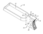
- FIG. 1 is a perspective view of a trigger assembly according to an embodiment of the present invention.
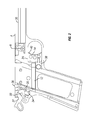
- FIG. 2 is a side section view of a pistol frame housing a fire control mechanism that includes a trigger assembly in accordance with FIG. 1 .
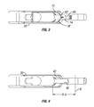
- FIG. 3 is a top section view of the pistol frame, fire control mechanism, and trigger assembly in accordance with FIG. 2 .
- FIG. 4 is a schematic top section view illustrating a gage location within the pistol frame of FIGS. 2 and 3 .
- FIG. is a top plane view of the trigger assembly in accordance with FIGS. 1-3 .
- FIG. 6 a side plane view of the trigger assembly in accordance with FIGS. 1-3 .
- FIG. 7 an end plane view of the trigger assembly in accordance with FIGS. 1-3 .
- a trigger assembly 10 includes a trigger bow 12 , which is swaged to a trigger shoe 14 .
- the trigger shoe 14 has first and second side surfaces 16 , 17 defining a thickness 18 , and has lower and upper end surfaces 20 , 21 defining a height 22 .
- the lower end surface 20 extends the full length of the trigger shoe 14 .
- the upper end surface 21 is limited to the top of a raised pad 24 , which protrudes from a top surface 26 extending forward from the raised pad 24 , the full length of the trigger shoe 14 .
- a pistol frame 30 houses the trigger bow 12 and a hammer 32 mounted on a hammer pin 33 , a sear 34 mounted on a sear pin 35 , and a disconnector 36 also mounted on the sear pin 35 .
- the frame 30 has a trigger slot 38 opened at a forward surface thereof, and has trigger grooves 40 extending forward from the trigger slot 38 .
- the trigger shoe 14 slides forward and aft within the trigger grooves 40 , and is adjusted to fit the trigger grooves 40 as described above.
- the frame 30 also includes an inward-facing stop surface 42 .
- the forwardmost position of the trigger bow 12 is set by this stop surface 42 .
- the location of the stop surface 42 relative to the sear pin 35 , controls whether the trigger bow 12 can move forward far enough to separate from the disconnector 36 and thereby cause forward and rearward play or float of the trigger shoe 14 .
- the stop surface 42 is formed by two concave surfaces on opposing inside walls of the frame 30 , it is challenging to verify the locating dimensions of the stop surface 42 and of the trigger bow 12 . In particular it is difficult to physically measure the edge or depth of a radial cut.
- a gage dimension BA was established, as shown in FIG. 4 .
- the dimension BA defines the width of a gage plug inserted from the top of the frame to measure the location of the trigger slot stop surface 42 relative to a datum B better shown in FIG. 2 . Adequate control of the dimension BA will ensure that the forward location of the trigger bow 12 will be sufficiently far from the sear-engagement position of the disconnector 36 , but not too far forward.
- a method for fitting the trigger assembly within the firearm is also provided. After providing the trigger assembly and firearm as discussed above, the distance between the stop surface and a datum plane is determined by inserting a gage (not shown for clarity) into the frame from the top. As a result, it is also determine if the distance between the stop surface and the sear pin is greater than or equal to a predetermined gage distance. If the distance is less than the predetermined gage distance, the frame is scrapped. If the distance is more or equal to the predetermined gage distance the trigger assembly is placed into the frame. If the trigger assembly cannot be inserted into the frame, a thickness is removed from the raised pad to allow the trigger shoe to slide within the trigger groove. The step may be repeated to ensure proper fit of the trigger shoe within the trigger groove. Then the trigger assembly is finally inserted into the frame to locate the trigger shoe within the trigger groove.
Landscapes
- Engineering & Computer Science (AREA)
- General Engineering & Computer Science (AREA)
- Footwear And Its Accessory, Manufacturing Method And Apparatuses (AREA)
Abstract
An trigger assembly with an improved trigger fit adjustment apparatus located within a 1911 pistol fire control mechanism. The trigger assembly has a trigger bow and a trigger shoe. The trigger shoe is connected to a forward end of the trigger bow. The trigger shoe has a pair of substantially parallel sides, a lower end connecting each of the pair of substantially parallel sides, and a raised pad extending from a top surface. The raised pad has an upper end that is substantially parallel to the lower end. The upper end of the raised pad is vertically spaced from the top surface.
Description
- This application claims the benefit of U.S. Provisional Application No. 61/412,632, filed Nov. 11, 2010, entitled “IMPROVED TRIGGER FIT ADJUSTMENT APPARATUS AND METHOD”, the aforementioned application being hereby incorporated by reference in its entirety.
- The present invention relates to firearm fire control mechanisms and, more particularly, to improving trigger fit within a 1911 pistol fire control mechanism.
- A typical 1911 pistol fire control mechanism includes a frame, a barrel mounted to a forward part or barrel bed of the frame, a slide mounted to the frame rearward of the barrel, and a fire control mechanism having components mounted within the slide and within the frame. The fire control mechanism components include a striker housed in the slide, a hammer mounted on a hammer pin within the frame, a sear mounted on a sear pin within the frame, a disconnector mounted on the same pin as the sear, and a trigger for actuating the sear, along with necessary springs.
- The trigger includes a shoe and a bow. The bow is internal to the frame while the shoe protrudes out of the grip portion of the frame via a trigger slot, which is formed at the forward side of the grip portion of the frame adjacent to the middle portion of the frame. The shoe is enclosed by a trigger guard formed in the middle portion of the frame. The trigger bow is biased forward within the frame, but can be moved rearward by the shoe for actuating the sear (via the disconnector) to fire the pistol. The trigger bow contacts the bottom of the disconnector. When the trigger bow is pushed rearward by the user it forces the bottom of the disconnector to rotate rearward around the sear pin. A leaf style spring pushes the sear and the disconnector forward until the trigger bow is pushed rearward by the user squeezing the shoe.
- Positioning of the trigger shoe within a 1911 pistol frame can affect perceived quality of operation. In particular, the shoe is held in its normal forward position by trigger grooves that are formed by side webs extending between the trigger guard and the frame. The shoe thickness and height help to determine how it moves along the grooves, with height being the dominant dimension. In particular, high spots on the trigger shoe can cause a sensation of hang up or pivoting when the trigger is squeezed. Thus, it is desirable to closely control fit of the trigger within the trigger grooves. However, known methods for controlling trigger fit require uniformly and repeatedly removing relatively small thicknesses of material from an entire end surface of a trigger. Thus, known methods for controlling trigger fit within the trigger grooves are time consuming, costly, and open to errors that are not easily corrected.
- Similarly, relative positioning of the disconnector and the trigger bow, within the 1911 fire control mechanism, can affect perceived quality of operation. The disconnector is mounted on the sear pin by a square hole that defines a movement envelope for the disconnector. The square hole permits the disconnector to rotate on the sear pin, and to move vertically between an upward (engaged) position and a downward (disengaged) position. In the engaged position, the top of the disconnector stands proud of the frame and the disconnector engages (actuates) the sear when the bottom of the disconnector is rotated rearward around the sear pin. In the disengaged position, the top of the disconnector sits flush with the frame and the disconnector does not engage the sear when the bottom of the disconnector is rotated rearward around the sear pin.
- When the bottom of the disconnector has fully rotated forward, the trigger bow may float free to move forward and rearward between the disconnector and the frame. This “play” of the trigger bow can result in a perception that the fire control mechanism is “loose” or of low quality. Accordingly, it is desirable to closely control fit of the trigger bow within the frame so that trigger bow play is prevented without defeating operation of the disconnector. However, controlling fit of the trigger bow has proven difficult in practice.
- According to embodiments of the present invention, a trigger apparatus comprising a trigger bow and a trigger shoe is provided with a raised pad at an end surface of the trigger shoe. The raised pad allows adjusting the height of the trigger shoe to match a mating trigger groove with minimal removal of material from the trigger shoe, and with reduced risk of causing an out-of-parallel condition during height adjustment. Removing material only from the raised pad results in the top finished surface of the trigger shoe remaining un-touched during final fit and assembly, enhancing usable life of the trigger.
- According to embodiments of the present invention, a pistol assembly and inspection method includes verifying precise location of a forward trigger bow stop surface within a pistol frame. For example, a square or round gage plug may be used to determine the stop surface location relative to a reference datum.
- According to embodiments of the present invention, a pistol frame includes a reference datum disposed along a first axis, and includes a trigger bow stop surface defining a plane perpendicular to a second axis. Distance from the stop surface plane to the first axis is verified to assure assembly of a fire control mechanism without trigger bow float.
- These and other objects, features and advantages of the present invention will become apparent in light of the detailed description of the best mode embodiment thereof, as illustrated in the accompanying drawings.
- The accompanying drawings, which are incorporated in and constitute a part of this specification, illustrate embodiments of the disclosure, and together with a general description of the disclosure given above, and the detailed description of the embodiments given below, serve to explain the principles of the disclosure.
-
FIG. 1 is a perspective view of a trigger assembly according to an embodiment of the present invention. -
FIG. 2 is a side section view of a pistol frame housing a fire control mechanism that includes a trigger assembly in accordance withFIG. 1 . -
FIG. 3 is a top section view of the pistol frame, fire control mechanism, and trigger assembly in accordance withFIG. 2 . -
FIG. 4 is a schematic top section view illustrating a gage location within the pistol frame ofFIGS. 2 and 3 . - FIG. is a top plane view of the trigger assembly in accordance with
FIGS. 1-3 . -
FIG. 6 a side plane view of the trigger assembly in accordance withFIGS. 1-3 . -
FIG. 7 an end plane view of the trigger assembly in accordance withFIGS. 1-3 . - Other features and advantages of the present disclosure will become apparent from the following detailed description, taken in conjunction with the accompanying drawings, which illustrate, by way of example, the principals of the invention.
- Referring to FIGS. 1 and 5-7, a
trigger assembly 10 according to an embodiment of the present invention includes atrigger bow 12, which is swaged to atrigger shoe 14. Thetrigger shoe 14 has first andsecond side surfaces thickness 18, and has lower andupper end surfaces height 22. In FIG. 1, thelower end surface 20 extends the full length of thetrigger shoe 14. By contrast, theupper end surface 21 is limited to the top of a raisedpad 24, which protrudes from atop surface 26 extending forward from the raisedpad 24, the full length of thetrigger shoe 14. In the prior art, in order to fit a trigger shoe into a matching trigger groove, all of a top surface of the trigger shoe would need to be ground or filed down. By contrast, the presently disclosedtrigger shoe 14 can be fitted to a matching trigger groove simply by filing down the raisedpad 24. - Referring to
FIGS. 2-4 , apistol frame 30 houses thetrigger bow 12 and ahammer 32 mounted on ahammer pin 33, asear 34 mounted on asear pin 35, and adisconnector 36 also mounted on thesear pin 35. With additional reference toFIG. 3 , theframe 30 has atrigger slot 38 opened at a forward surface thereof, and hastrigger grooves 40 extending forward from thetrigger slot 38. Thetrigger shoe 14 slides forward and aft within thetrigger grooves 40, and is adjusted to fit thetrigger grooves 40 as described above. - The
frame 30 also includes an inward-facingstop surface 42. The forwardmost position of thetrigger bow 12 is set by thisstop surface 42. Thus, the location of thestop surface 42, relative to thesear pin 35, controls whether thetrigger bow 12 can move forward far enough to separate from thedisconnector 36 and thereby cause forward and rearward play or float of thetrigger shoe 14. - However, because the
stop surface 42 is formed by two concave surfaces on opposing inside walls of theframe 30, it is challenging to verify the locating dimensions of thestop surface 42 and of thetrigger bow 12. In particular it is difficult to physically measure the edge or depth of a radial cut. To get around this problem, a gage dimension BA was established, as shown inFIG. 4 . The dimension BA defines the width of a gage plug inserted from the top of the frame to measure the location of the trigger slot stopsurface 42 relative to a datum B better shown inFIG. 2 . Adequate control of the dimension BA will ensure that the forward location of thetrigger bow 12 will be sufficiently far from the sear-engagement position of thedisconnector 36, but not too far forward. - A method for fitting the trigger assembly within the firearm is also provided. After providing the trigger assembly and firearm as discussed above, the distance between the stop surface and a datum plane is determined by inserting a gage (not shown for clarity) into the frame from the top. As a result, it is also determine if the distance between the stop surface and the sear pin is greater than or equal to a predetermined gage distance. If the distance is less than the predetermined gage distance, the frame is scrapped. If the distance is more or equal to the predetermined gage distance the trigger assembly is placed into the frame. If the trigger assembly cannot be inserted into the frame, a thickness is removed from the raised pad to allow the trigger shoe to slide within the trigger groove. The step may be repeated to ensure proper fit of the trigger shoe within the trigger groove. Then the trigger assembly is finally inserted into the frame to locate the trigger shoe within the trigger groove.
- Although this invention has been shown and described with respect to the detailed embodiments thereof, it will be understood by those skilled in the art that various changes in form and detail thereof may be made without departing from the spirit and the scope of the invention.
Claims (19)
1. A trigger assembly for use within a frame of a firearm to improve trigger fit adjustment, the trigger assembly comprising:
a trigger bow; and
a trigger shoe being connected to a forward end of the trigger bow and having:
a pair of sides,
a lower end surface connecting the pair of sides, and
a raised pad extending from a top surface and having an upper end surface being vertically spaced from the lower end surface, the upper end surface of the raised pad being vertically spaced from the top surface.
2. The trigger assembly according to claim 1 , wherein the trigger bow and the trigger shoe being swaged together.
3. The trigger assembly according to claim 1 , wherein the trigger shoe being adapted to slide along a trigger groove in the frame.
4. The trigger assembly according to claim 3 , wherein the top surface of the trigger shoe is spaced from the lower end surface at a height that is substantially less than a height of the trigger groove.
5. The trigger assembly according to claim 3 , wherein the upper end surface of the raised pad is spaced from the lower end surface at a height that is substantially equivalent to a height of the trigger groove.
6. The trigger assembly according to claim 1 , wherein the upper end surface being substantially parallel to the lower end surface.
7. The trigger assembly according to claim 1 , wherein the pair of sides are substantially parallel to each other.
8. The trigger assembly according to claim 1 , wherein the lower end surface extends substantially the full length of the trigger shoe.
9. The trigger assembly according to claim 1 , wherein the top surface extends forward from the raised pad.
10. A firearm comprising:
a frame having a trigger slot and a trigger groove extending forward from the trigger slot; and
a trigger assembly at least partially located within the trigger groove, the trigger assembly having:
a trigger bow;
a trigger shoe being connected to a forward end of the trigger bow and having:
a pair of sides,
a lower end surface connecting each of the pair of sides, and
a raised pad extending from a top surface and having an upper end surface vertically spaced from the lower end surface, the upper end surface of the raised pad being vertically spaced from the top surface.
11. The firearm according to claim 10 , wherein the trigger bow and the trigger shoe being swaged together.
12. The firearm according to claim 10 , wherein the trigger shoe being adapted to slide along the trigger groove of the frame.
13. The firearm according to claim 10 , wherein the top surface of the trigger shoe is spaced from the lower end surface at a height that is substantially less than a height of the trigger groove.
14. The firearm according to claim 10 , wherein the upper end surface of the raised pad is spaced from the lower end surface at a height that is substantially equivalent to a height of the trigger groove.
15. The firearm according to claim 10 , wherein the upper end surface being substantially parallel to the lower end surface.
16. The firearm according to claim 10 , wherein the pair of sides are substantially parallel to each other.
17. The firearm according to claim 10 , wherein the lower end surface extends substantially the full length of the trigger shoe.
18. The firearm according to claim 10 , wherein the top surface extends forward from the raised pad.
19. A method for fitting a trigger assembly within a firearm, the method comprising the steps of:
providing a frame having:
a trigger slot,
a trigger groove extending forward from the trigger slot,
a stop surface located rearward from the trigger groove, and
a sear pin spaced rearward from the stop surface;
providing a trigger assembly having:
a trigger bow; and
a trigger shoe being connected to a forward end of the trigger bow and having:
a pair of sides,
a lower end surface connecting the pair of sides, and
a raised pad extending from a top surface and having an upper end surface being vertically spaced from the lower end surface, the upper end surface of the raised pad being vertically spaced from the top surface;
determining the distance between the stop surface and the sear pin;
determining if the distance between the stop surface and the sear pin is greater than or equal to a predetermined gage distance;
removing a thickness from the raised pad to allow the trigger shoe to slide within the trigger groove; and
inserting the trigger assembly into the frame to locate the trigger shoe within the trigger groove.
Priority Applications (1)
| Application Number | Priority Date | Filing Date | Title |
|---|---|---|---|
| US13/290,341 US20120117841A1 (en) | 2010-11-11 | 2011-11-07 | Trigger fit adjustment apparatus and method |
Applications Claiming Priority (2)
| Application Number | Priority Date | Filing Date | Title |
|---|---|---|---|
| US41263210P | 2010-11-11 | 2010-11-11 | |
| US13/290,341 US20120117841A1 (en) | 2010-11-11 | 2011-11-07 | Trigger fit adjustment apparatus and method |
Publications (1)
| Publication Number | Publication Date |
|---|---|
| US20120117841A1 true US20120117841A1 (en) | 2012-05-17 |
Family
ID=46046510
Family Applications (1)
| Application Number | Title | Priority Date | Filing Date |
|---|---|---|---|
| US13/290,341 Abandoned US20120117841A1 (en) | 2010-11-11 | 2011-11-07 | Trigger fit adjustment apparatus and method |
Country Status (1)
| Country | Link |
|---|---|
| US (1) | US20120117841A1 (en) |
Cited By (21)
| Publication number | Priority date | Publication date | Assignee | Title |
|---|---|---|---|---|
| US20130180394A1 (en) * | 2012-01-17 | 2013-07-18 | Double Nickel Holdings, Llc | Hammerless, Striker Fired Model 1911 Handgun and Associated Methods |
| US9052149B2 (en) | 2012-09-04 | 2015-06-09 | Terrence Dwight Bender | Trigger with adjustable shoe |
| US9175917B2 (en) | 2013-12-03 | 2015-11-03 | Terrence Dwight Bender | Trigger with cam |
| USD746402S1 (en) | 2014-08-14 | 2015-12-29 | Double Nickel Holdings, Llc | Sear assembly for a striker fired handgun |
| US9410760B2 (en) | 2014-07-30 | 2016-08-09 | Double Nickel Holdings, Llc | Sear assembly for hammerless, striker fired handgun |
| US20180080731A1 (en) * | 2016-09-22 | 2018-03-22 | Skunk Labs Llc | Firearms Trigger Assembly |
| US10006733B2 (en) | 2014-10-22 | 2018-06-26 | In Ovation Llc | Non-fouling trigger |
| US10126082B2 (en) * | 2015-09-01 | 2018-11-13 | Skunk Labs Llc | Sear mechanism for firearms |
| WO2018236345A1 (en) * | 2017-06-20 | 2018-12-27 | Pressure Break, Llc | RELAXATION |
| US20190041150A1 (en) * | 2017-08-07 | 2019-02-07 | Cor34, LLC | Adjustable trigger assembly |
| US10247503B2 (en) | 2008-10-14 | 2019-04-02 | Pressure Break, Llc | Trigger |
| US20190137206A1 (en) * | 2017-11-06 | 2019-05-09 | Cor34, LLC | Custom trigger body |
| US11187482B2 (en) | 2020-03-31 | 2021-11-30 | Pressure Break, Llc | Trigger assembly |
| US11421955B1 (en) * | 2021-01-28 | 2022-08-23 | Scott Matheson | Trigger pull cover |
| US11592255B2 (en) | 2020-01-20 | 2023-02-28 | In Ovation Llc | Fire control assembly |
| US11719499B1 (en) | 2019-11-27 | 2023-08-08 | Sean Hynds | Adjustable trigger assembly and method of adjusting pre-travel distance |
| US11927408B2 (en) | 2020-01-20 | 2024-03-12 | In Ovation Llc | Fire control assembly |
| USD1024253S1 (en) | 2020-07-03 | 2024-04-23 | In Ovation Llc | Trigger cassette |
| US12007199B2 (en) * | 2022-07-29 | 2024-06-11 | Oracle Arms, Llc | Firearm with various improvements |
| US20250146778A1 (en) * | 2023-11-02 | 2025-05-08 | Warwick Tactical LLC | Front removeable trigger shoe |
| US12379178B1 (en) * | 2024-05-13 | 2025-08-05 | Brandon Vitulli | Modular firearm trigger system |
Citations (10)
| Publication number | Priority date | Publication date | Assignee | Title |
|---|---|---|---|---|
| US3016646A (en) * | 1959-12-02 | 1962-01-16 | Katherine B Groves | Hammer assembly for a pistol |
| US4416078A (en) * | 1980-01-14 | 1983-11-22 | Cop, Inc. | Handgun |
| US4744165A (en) * | 1986-06-18 | 1988-05-17 | Amf Mares S.P.A. | Trigger |
| US5822903A (en) * | 1997-08-08 | 1998-10-20 | Craig T. Luttes | Externally adjustable slide trigger assemblies for handguns |
| US5962804A (en) * | 1998-06-16 | 1999-10-05 | Lee; Cheng-Ho | Actuating device of a dynamite gun |
| US6070512A (en) * | 1998-08-14 | 2000-06-06 | Rohrbaugh; Karl | Handgun and method of operating handgun |
| US20010016998A1 (en) * | 1997-10-31 | 2001-08-30 | Daniel L. Chapman | Passive safety mechanism |
| US6298594B1 (en) * | 1998-01-09 | 2001-10-09 | Sandy L. Strayer | Interchangeable trigger system firearms |
| US20050229460A1 (en) * | 2000-04-28 | 2005-10-20 | Lafleur Gary K | Detachable pistol firing assembly |
| US7010878B1 (en) * | 2000-04-10 | 2006-03-14 | Wilson's Gun Shop, Inc. | Trigger system and method of installing same |
-
2011
- 2011-11-07 US US13/290,341 patent/US20120117841A1/en not_active Abandoned
Patent Citations (10)
| Publication number | Priority date | Publication date | Assignee | Title |
|---|---|---|---|---|
| US3016646A (en) * | 1959-12-02 | 1962-01-16 | Katherine B Groves | Hammer assembly for a pistol |
| US4416078A (en) * | 1980-01-14 | 1983-11-22 | Cop, Inc. | Handgun |
| US4744165A (en) * | 1986-06-18 | 1988-05-17 | Amf Mares S.P.A. | Trigger |
| US5822903A (en) * | 1997-08-08 | 1998-10-20 | Craig T. Luttes | Externally adjustable slide trigger assemblies for handguns |
| US20010016998A1 (en) * | 1997-10-31 | 2001-08-30 | Daniel L. Chapman | Passive safety mechanism |
| US6298594B1 (en) * | 1998-01-09 | 2001-10-09 | Sandy L. Strayer | Interchangeable trigger system firearms |
| US5962804A (en) * | 1998-06-16 | 1999-10-05 | Lee; Cheng-Ho | Actuating device of a dynamite gun |
| US6070512A (en) * | 1998-08-14 | 2000-06-06 | Rohrbaugh; Karl | Handgun and method of operating handgun |
| US7010878B1 (en) * | 2000-04-10 | 2006-03-14 | Wilson's Gun Shop, Inc. | Trigger system and method of installing same |
| US20050229460A1 (en) * | 2000-04-28 | 2005-10-20 | Lafleur Gary K | Detachable pistol firing assembly |
Cited By (31)
| Publication number | Priority date | Publication date | Assignee | Title |
|---|---|---|---|---|
| US10247503B2 (en) | 2008-10-14 | 2019-04-02 | Pressure Break, Llc | Trigger |
| US8720096B2 (en) * | 2012-01-17 | 2014-05-13 | Double Nickel Holdings, Llc | Hammerless, striker fired model 1911 handgun and associated methods |
| US20130180394A1 (en) * | 2012-01-17 | 2013-07-18 | Double Nickel Holdings, Llc | Hammerless, Striker Fired Model 1911 Handgun and Associated Methods |
| US9052149B2 (en) | 2012-09-04 | 2015-06-09 | Terrence Dwight Bender | Trigger with adjustable shoe |
| US9175917B2 (en) | 2013-12-03 | 2015-11-03 | Terrence Dwight Bender | Trigger with cam |
| US9696103B2 (en) | 2013-12-03 | 2017-07-04 | In Ovation Llc | Trigger with cam |
| US9410760B2 (en) | 2014-07-30 | 2016-08-09 | Double Nickel Holdings, Llc | Sear assembly for hammerless, striker fired handgun |
| USD746402S1 (en) | 2014-08-14 | 2015-12-29 | Double Nickel Holdings, Llc | Sear assembly for a striker fired handgun |
| US10006733B2 (en) | 2014-10-22 | 2018-06-26 | In Ovation Llc | Non-fouling trigger |
| US10126082B2 (en) * | 2015-09-01 | 2018-11-13 | Skunk Labs Llc | Sear mechanism for firearms |
| US20180080731A1 (en) * | 2016-09-22 | 2018-03-22 | Skunk Labs Llc | Firearms Trigger Assembly |
| US11385009B2 (en) * | 2016-09-22 | 2022-07-12 | Daniel Defense, Llc | Firearms trigger assembly |
| WO2018236345A1 (en) * | 2017-06-20 | 2018-12-27 | Pressure Break, Llc | RELAXATION |
| US20190041150A1 (en) * | 2017-08-07 | 2019-02-07 | Cor34, LLC | Adjustable trigger assembly |
| US11248869B2 (en) * | 2017-08-07 | 2022-02-15 | Cor34 Llc | Adjustable trigger assembly |
| US20190137206A1 (en) * | 2017-11-06 | 2019-05-09 | Cor34, LLC | Custom trigger body |
| US12498191B1 (en) | 2019-11-27 | 2025-12-16 | Sean Hynds | Adjustable trigger assembly and method of adjusting pre-travel distance |
| US11719499B1 (en) | 2019-11-27 | 2023-08-08 | Sean Hynds | Adjustable trigger assembly and method of adjusting pre-travel distance |
| USD1010053S1 (en) * | 2019-11-27 | 2024-01-02 | Sean Hynds | Front lateral cross member of a trigger bow |
| US11927408B2 (en) | 2020-01-20 | 2024-03-12 | In Ovation Llc | Fire control assembly |
| US11592255B2 (en) | 2020-01-20 | 2023-02-28 | In Ovation Llc | Fire control assembly |
| US11187482B2 (en) | 2020-03-31 | 2021-11-30 | Pressure Break, Llc | Trigger assembly |
| USD1024253S1 (en) | 2020-07-03 | 2024-04-23 | In Ovation Llc | Trigger cassette |
| US11421955B1 (en) * | 2021-01-28 | 2022-08-23 | Scott Matheson | Trigger pull cover |
| US12007199B2 (en) * | 2022-07-29 | 2024-06-11 | Oracle Arms, Llc | Firearm with various improvements |
| US12379185B2 (en) | 2022-07-29 | 2025-08-05 | Oa Defense Llc | Modular firearm block |
| US12535295B2 (en) | 2022-07-29 | 2026-01-27 | Oa Defense Llc | Firearms with an ambidextrous slide stop and/or relief |
| US12584712B2 (en) | 2022-07-29 | 2026-03-24 | Oa Defense Llc | Firearms with an ambidextrous slide stop and/or relief |
| US20250146778A1 (en) * | 2023-11-02 | 2025-05-08 | Warwick Tactical LLC | Front removeable trigger shoe |
| US12584706B2 (en) * | 2023-11-02 | 2026-03-24 | Warwick Tactical LLC | Front removeable trigger shoe |
| US12379178B1 (en) * | 2024-05-13 | 2025-08-05 | Brandon Vitulli | Modular firearm trigger system |
Similar Documents
| Publication | Publication Date | Title |
|---|---|---|
| US20120117841A1 (en) | Trigger fit adjustment apparatus and method | |
| US7392611B2 (en) | Apparatus and method for firearm takedown | |
| US9952011B2 (en) | Rotationally actuated and dual pin supported linkage incorporated into a lower receiver of a firearm for establishing a last shot hold open condition with an upwardly displaceable magazine follower | |
| US10030927B1 (en) | Sear system for a firearm | |
| US9625227B2 (en) | Firing mechanism for a firearm | |
| US8225541B2 (en) | Magazine for a firearm | |
| US8935871B2 (en) | Hand gun | |
| US8510980B2 (en) | Reset assist mechanism | |
| US8640375B2 (en) | 1911 handgun disassembly tool and method of making same | |
| US10371478B2 (en) | Bench block to aid in disassembling and cleaning a handgun and methods of making and using same | |
| KR100304087B1 (en) | magazine | |
| US11248869B2 (en) | Adjustable trigger assembly | |
| US10809034B2 (en) | Barrel system for a firearm | |
| US20190242669A1 (en) | Pistol frame disassembly bed | |
| US10422598B2 (en) | System and method for magazine with folded feed lips | |
| US9958224B2 (en) | Pistol frame disassembly bed | |
| US4574509A (en) | Ambidextrous cartridge magazine retaining catch for self loading fire arms | |
| US9548567B2 (en) | Electrical card connector capable of indicating card's false insertion | |
| US20180058784A1 (en) | System and method for magazine with rolled feed lips | |
| KR101937775B1 (en) | Trigger Assembly of Pistols | |
| US10500749B2 (en) | Cutting machine | |
| US7762115B2 (en) | Loft and lie adjustment tool for golf clubs | |
| US20070137472A1 (en) | Handgun with two-sided breechblock mechanism | |
| US9605920B2 (en) | Hammer strut support | |
| EP1510774A1 (en) | An alignment device for a firearm |
Legal Events
| Date | Code | Title | Description |
|---|---|---|---|
| AS | Assignment |
Owner name: SMITH & WESSON CORP., MASSACHUSETTS Free format text: ASSIGNMENT OF ASSIGNORS INTEREST;ASSIGNORS:JOUBERT, SETH;BELIN, HERB;SIGNING DATES FROM 20111103 TO 20111107;REEL/FRAME:027184/0191 |
|
| STCB | Information on status: application discontinuation |
Free format text: ABANDONED -- FAILURE TO RESPOND TO AN OFFICE ACTION |