US20110240323A1 - vibratory mechanism for a pile driver and a pile driver - Google Patents
vibratory mechanism for a pile driver and a pile driver Download PDFInfo
- Publication number
- US20110240323A1 US20110240323A1 US13/132,988 US200913132988A US2011240323A1 US 20110240323 A1 US20110240323 A1 US 20110240323A1 US 200913132988 A US200913132988 A US 200913132988A US 2011240323 A1 US2011240323 A1 US 2011240323A1
- Authority
- US
- United States
- Prior art keywords
- housing
- fluid
- vibration member
- vibration
- vibratory mechanism
- Prior art date
- Legal status (The legal status is an assumption and is not a legal conclusion. Google has not performed a legal analysis and makes no representation as to the accuracy of the status listed.)
- Abandoned
Links
- 230000007246 mechanism Effects 0.000 title claims abstract description 78
- 230000003068 static effect Effects 0.000 claims abstract description 47
- 239000012530 fluid Substances 0.000 claims description 113
- 238000002485 combustion reaction Methods 0.000 claims description 8
- 238000013459 approach Methods 0.000 claims description 2
- 230000033001 locomotion Effects 0.000 description 8
- 230000005540 biological transmission Effects 0.000 description 5
- 230000008878 coupling Effects 0.000 description 5
- 238000010168 coupling process Methods 0.000 description 5
- 238000005859 coupling reaction Methods 0.000 description 5
- 239000003570 air Substances 0.000 description 4
- 238000006073 displacement reaction Methods 0.000 description 4
- 230000003247 decreasing effect Effects 0.000 description 3
- 239000012080 ambient air Substances 0.000 description 2
- 238000004891 communication Methods 0.000 description 2
- 230000000694 effects Effects 0.000 description 2
- 238000012546 transfer Methods 0.000 description 2
- 230000002411 adverse Effects 0.000 description 1
- 239000010426 asphalt Substances 0.000 description 1
- 239000004568 cement Substances 0.000 description 1
- 230000006835 compression Effects 0.000 description 1
- 238000007906 compression Methods 0.000 description 1
- 239000004567 concrete Substances 0.000 description 1
- 238000013016 damping Methods 0.000 description 1
- 230000007423 decrease Effects 0.000 description 1
- 238000013461 design Methods 0.000 description 1
- 238000012423 maintenance Methods 0.000 description 1
- 230000010363 phase shift Effects 0.000 description 1
- 230000001739 rebound effect Effects 0.000 description 1
- 239000002689 soil Substances 0.000 description 1
- 239000004575 stone Substances 0.000 description 1
- 230000001360 synchronised effect Effects 0.000 description 1
Images


Classifications
-
- E—FIXED CONSTRUCTIONS
- E02—HYDRAULIC ENGINEERING; FOUNDATIONS; SOIL SHIFTING
- E02D—FOUNDATIONS; EXCAVATIONS; EMBANKMENTS; UNDERGROUND OR UNDERWATER STRUCTURES
- E02D7/00—Methods or apparatus for placing sheet pile bulkheads, piles, mouldpipes, or other moulds
- E02D7/18—Placing by vibrating
-
- B—PERFORMING OPERATIONS; TRANSPORTING
- B06—GENERATING OR TRANSMITTING MECHANICAL VIBRATIONS IN GENERAL
- B06B—METHODS OR APPARATUS FOR GENERATING OR TRANSMITTING MECHANICAL VIBRATIONS OF INFRASONIC, SONIC, OR ULTRASONIC FREQUENCY, e.g. FOR PERFORMING MECHANICAL WORK IN GENERAL
- B06B1/00—Methods or apparatus for generating mechanical vibrations of infrasonic, sonic, or ultrasonic frequency
- B06B1/18—Methods or apparatus for generating mechanical vibrations of infrasonic, sonic, or ultrasonic frequency wherein the vibrator is actuated by pressure fluid
- B06B1/183—Methods or apparatus for generating mechanical vibrations of infrasonic, sonic, or ultrasonic frequency wherein the vibrator is actuated by pressure fluid operating with reciprocating masses
Definitions
- aspects of the invention relate to a vibratory mechanism comprising a static part and a dynamic part being movable with respect to the static part.
- Such a vibratory mechanism is known from U.S. Pat. No. 5,088,565.
- the static part of the prior art mechanism is attached to a cable of a crane and the dynamic part comprises jaws for clamping a pile to be driven into the ground or to be extracted out of the ground.
- the dynamic part is provided with a pair of eccentrically rotatable weights which can be rotatably driven by a hydraulic motor. The weights rotate in opposite directions with respect to each other resulting in a vertical vibration of the dynamic part.
- a disadvantage of the known mechanism is that bearings of the rotatable weights are heavily loaded resulting in relatively high operational costs due to maintenance and replacement of the bearings.
- SU 631 597 is related to a vibrating hammer which comprises an inner casing that is provided with a crankshaft which is connected to a piston via a connecting rod.
- the piston is movable within a cylinder.
- the crankshaft is driven via compressed air which is fed to the cylinder through a pipe being provided with a control valve for allowing compressed air to the cylinder.
- the mechanism is unbalanced.
- the inner casing is connected to an outer casing through springs. Under operating conditions, the inner casing will vibrate within the outer casing due to the unbalanced mechanism. Under certain conditions the inner casing hits the outer casing at the upper or lower inner side thereof, depending on the presence of hitting plates at the outer casing.
- a mechanism having an aspect of the invention includes a static part that is provided with a drivable crankshaft and a dynamic part that comprises a housing and a vibration member being drivably coupled to the crankshaft through a connecting rod and linearly movable with respect to the housing in a direction of vibration, wherein said housing is resiliently coupled to the vibration member via a fluid spring, wherein the mechanism is adapted such that under operating conditions the vibration member is driven upon driving the crankshaft by driving means.
- the vibration member Upon driving the crankshaft the vibration member will vibrate linearly with respect to the housing of the dynamic part. Due to the resilient coupling between the vibration member and the housing, the housing of the dynamic part will vibrate as well.
- the housing of the dynamic part may be provided with clamping means for clamping a pile. The mechanism provides the opportunity to select the rotation speed of the crankshaft, the weights of the vibration member and the housing and the degree of resiliency between the vibration member and the housing such that the dynamic part vibrates at a certain frequency, whereas transfer of inertia forces in the mechanism via the crankshaft to the remainder of the static part is minimized.
- reciprocating forces of the first order can be used to balance the vibrational forces of the housing of the dynamic part on the crankshaft under certain conditions. This means that forces on crankshaft bearings in the static part are minimized, hence reducing wear and operational costs.
- reciprocating forces of the first order is typically used in case of balancing reciprocating piston-crank-connecting rod mechanisms, such as present in internal combustion engines, in order to indicate inertial forces of the piston acting in the direction of piston movement and occurring at the frequency of rotation of the crank.
- crank-connecting rod mechanism can be built in a compact way compared to a conventional dynamic part comprising oppositely rotating weights, since in the latter case at least two rotatable weights must be located next to each other as seen in horizontal direction so as to achieve a vertical vibration.
- sudden peak forces on the housing are not directly transferred to the vibration member and the static part.
- a sudden peak force may typically happen in a pile driver if a pile is fixed to the housing to be driven into the ground and the pile touches a rigid layer or a stone or the like.
- the resulting so-called rebound effect is smoothly transferred to the static part by the mechanism.
- the fluid spring of the mechanism could be replaced by an alternative resiliency, for example a coil spring.
- crankshaft and the piston in the mechanism as disclosed in SU 631 597 is mounted in the same inner casing.
- the vibratory mechanism herein enables to solve the problem due to providing the static part with the crankshaft and providing the dynamic part with the vibration member. This also allows a direct and simple coupling between the crankshaft and a driving means for driving the crankshaft. Furthermore, the crankshaft bearings are not adversely affected by sudden loads on the dynamic part.
- the characteristics of the fluid spring can be adjusted.
- the characteristics can be manipulated such that the natural frequency of the mass-spring system comprising the vibration member and the fluid spring is similar to or approaches the frequency of the crankshaft under operating conditions. If this situation is achieved under operating conditions the inertia force of the vibration member on the crankshaft is minimized.
- the relationship between the mentioned frequencies may be slightly influenced by the weight of the housing of the dynamic part, but this weight will be high with respect to the weight of the vibration member, in practice, such that the weight ratio is rather stable under operating conditions.
- the natural frequency of the mass-spring system comprising the vibration member and the fluid spring is much higher than the natural frequency of the mass-spring system comprising the housing of the dynamic part and the fluid spring.
- the fluid spring characteristics can be influenced by modifying its fluid properties, for example.
- the spring characteristics could be influenced by an actuator.
- the vibration member is a piston and the housing comprises a cylinder within which the piston is slidable, and the fluid spring is formed by a fluid chamber being present between the piston and the cylinder.
- the fluid chamber functions as a fluid spring. It is noted that a part of the connecting rod weight contributes to the vibration member weight.
- the fluid spring is formed by two fluid chambers located at opposite sides of the piston. This provides more flexibility in influencing the spring characteristics of the resiliency between the piston and the cylinder.
- the fluid chambers may be allowed to communicate with each other through a controllable valve.
- a controllable valve When opening the valve and moving the piston within the cylinder the fluid will flow from the fluid chamber of which the volume reduces to the fluid chamber of which the volume increases. If the valve is open such that no compression/expansion occurs in the fluid chambers the spring characteristics created by the fluid chambers are negligible. This may be desired under certain conditions, for example in case of a pile driver which is starting-up. In that case the housing should not be driven before the piston vibration has reached a certain frequency.
- the valve When the valve is open the piston may vibrate within the cylinder without driving the housing of the dynamic part.
- the valve may be closed at a piston frequency exceeding for example 1200 rpm, such that the starting-up period during which the frequency of the housing of the dynamic part is relatively low, is short.
- the fluid chambers communicate with the ambient air through a controllable valve during the starting-up period.
- the mechanism comprises at least two vibration members, wherein the mechanism is adapted such that under operating conditions the vibration members can be driven in opposite directions, for example in counter phase.
- This allows the opportunity to increase the vibration frequency of the vibration members to a relatively high level, for example the operational frequency in case of a pile driver, whereas the vibration of the housing in the direction of vibration remains negligible, because the forces of the oppositely moving vibration members on the housing via the resiliency can be balanced.
- the characteristics of the resiliency between the housing and the vibration members can be varied. Due to this feature the resiliency can be adjusted such that the counter force of the resiliency on the vibration members at least partly reduce the inertia forces of the vibration members on the static part during the increase of the vibration frequency of the vibration members whereas the vibration of the housing remains negligible.
- the mechanism can be set such that the vibration members move synchronously in the same direction. In practice, during increase of the frequency the resiliency will be adjusted to a stiffer level.
- the vibrating members are pistons moving oppositely in corresponding cylinders and the resiliency is formed by the fluid chambers located at opposite sides of each of the pistons
- the fluid pressure in the fluid chambers can be increased during the period of increasing the frequency of the reciprocating speed of the pistons in order to reduce the reciprocating inertial forces of the pistons on the static part.
- the fluid chamber of one cylinder can communicate with the fluid chamber of the other cylinder such that under operating conditions a decreasing fluid chamber volume in one cylinder can communicate with an increasing fluid chamber volume in the other cylinder.
- the fluid chambers can be connected to each other in fluid communication which means that the piston in one cylinder pushes the fluid from the fluid chamber in that cylinder to the fluid chamber of the other cylinder, whereas the piston of the other cylinder synchronously sucks the fluid from the one cylinder.
- the pistons vibrate within the cylinders without driving the housing of the dynamic part.
- two cylinders may be disposed parallel to each other and the fluid chambers at the same side of the pistons can be connected to each other.
- the pistons can be driven in counter phase such that the volumes of the mutually connected fluid chambers at the same side of the pistons also vary in counter phase.
- the sum of the volumes of the connected fluid chambers substantially remains the same.
- the fluid communication can be effected by a controllable valve or the like.
- the mechanism may comprise adjusting device for adjusting the stroke of the vibration member with respect to the eccentricity of the crankshaft in order to minimize the amplitude of the vibration member during a starting-up period.
- the fluid spring can communicate with a compressor for increasing or decreasing the pressure of the fluid in the fluid spring. This feature provides the opportunity to influence the amplitude of the housing, for example.
- a variable pressure, depending on the operation frequency is also conceivable.
- Alternative adjusting devices for manipulating the fluid spring characteristics are conceivable.
- the housing of the dynamic part and the static part may be connected to each other via a spring and/or a damper so as to create a coupling between the static part and the dynamic part in addition to the coupling via the connecting rod, and to reduce any transfer of vibrations from the dynamic part to the static part.
- a first part of the connecting rod is guided by a crosshead guide in the static part or in the dynamic part and a second part thereof being fixed to the vibration member is movable along its longitudinal center line only. This means that the second part has a one-dimensional motion in the direction of vibration of the vibration member.
- the vibration speed of the vibration member, the weight of the housing and the characteristics of the resiliency between the housing and the vibration member are selected such that the vibration member and the housing substantially vibrate in counter phase under operating conditions, and the weight of the vibration member is selected such that its inertia force of the first order substantially balances the inertia force of the housing.
- the weight of the vibration member and the housing may be selected first and the characteristics of the resiliency between the housing and the vibration member is then adjusted to optimize the functioning of the mechanism.
- the characteristics of the resiliency can be influenced by the volume of the fluid chamber in case of a fluid spring.
- An aspect of the invention is also related to a pile driver comprising a vibratory mechanism as described hereinbefore.
- the static part of the vibratory mechanism may be provided with a drive for driving the crankshaft.
- a drive for driving the crankshaft This is advantageous in terms of mobility compared to a mobile pile driver of which the drive is located on the ground. This is also advantageous in terms of efficiency and reduced complexity with respect to conventional pile drivers in which hydraulic systems are used and power must be transmitted from a power supply on the ground to the static part.
- the drive is an internal combustion engine.
- FIG. 1 is a schematic view of an embodiment of the vibratory mechanism.
- FIG. 2 is a perspective view of an alternative embodiment of the vibratory mechanism of FIG. 1 .
- FIG. 3 is a similar view as FIG. 1 of an alternative embodiment on a smaller scale.
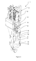
- FIG. 4 is a similar view as FIG. 2 of another alternative embodiment.
- FIG. 1 shows an embodiment of the vibratory mechanism 1 according to the invention.
- the vibratory mechanism 1 is part of a pile driver in this example, but may be suitable for alternative technical devices.
- the vibratory mechanism 1 as shown in FIG. 1 comprises a static part 2 and a dynamic part 3 .
- the dynamic part 3 is movable with respect to the static part 2 .
- the static part 2 is provided with a lifting eye 4 .
- the lifting eye 4 suspends from a cable of a crane (not shown).
- the dynamic part 3 is provided with a pair of clamps 5 for clamping a pile to be driven into the ground or to be extracted out of the ground.
- the pair of clamps 5 may be driven mechanically, hydraulically or the like.
- the dynamic part 3 oscillates in a vertical direction at a predetermined frequency and with a predetermined amplitude with respect to the static part 2 .
- FIG. 1 shows that the static part 2 is provided with a drivable crankshaft 6 .
- the crankshaft 6 comprises two crankpins located eccentrically with respect to the center line of the crankshaft 6 .
- the dynamic part 3 is provided with two pistons 7 as vibration members.
- Each of the pistons 7 is coupled to the crankshaft 6 through a connecting rod 8 .
- the connecting rod 8 comprises a first part 9 which is guided by a crosshead guide 10 in the static part 2 , and a second part 11 which is movable along its longitudinal center line only.
- the piston 7 is fixed to the second part 11 .
- a through hole in the dynamic part 3 through which the second part 11 of the connecting rod 8 moves up and down may have the shape of the cross-sectional area of the second part 11 and the dimensions of the cross-sectional area of the through hole may be slightly larger than those of the second part 11 .
- crankshaft 6 is driven by an internal combustion engine 12 .
- Alternative driving means are conceivable, for example a hydraulic or electric motor.
- An advantage of applying the internal combustion engine 12 is that it can be used as stand-alone unit in the static part 2 .
- the piston is driven upon driving the crankshaft 6 by driving means.
- the dynamic part 3 further comprises a housing in the form of cylinders 13 which function as guides for guiding the pistons 7 .
- the cylinders 13 have a fixed position with respect to the dynamic part 3 .
- the pistons 7 are slidable within the cylinders 13 .
- the cylinders 13 are filled with a fluid, for example air.
- the piston 7 divides the cylinder space into two fluid chambers 14 , 15 located at opposite sides of the piston 7 . If the fluid chambers 14 , 15 are closed spaces or nearly closed spaces, they form a fluid spring.
- the housing of the dynamic part 3 or the cylinder 13 is resiliently coupled to the piston 7 .
- the fluid is a gas
- the fluid chambers 14 , 15 form a gas spring.
- the fluid spring characteristics can be adjusted by modifying the fluid properties in the fluid chambers 14 , 15 .
- the fluid chambers 14 , 15 can communicate with each other through a controllable valve 16 .
- the valve 16 When the valve 16 is fully opened the fluid chambers 14 , 15 communicate with each other. This means that in case of a downward displacement of the piston 7 the fluid from the lower fluid chamber 15 is pressed to the upper fluid chamber 14 via the valve 16 . In that case the housing of the dynamic part 3 or the cylinder 13 will not follow the displacement of the piston 7 .
- the valve 16 is closed and the piston 7 is displaced down-wardly the fluid in the lower fluid chamber 15 will be compressed and the fluid in the upper fluid chamber 14 will be expanded.
- the cylinder 13 will follow this displacement in downward direction.
- the weight of the housing of the dynamic part 3 and the properties of the fluid in the fluid chambers 14 , 15 the housing of the dynamic part 3 will follow the piston movement at a certain phase shift, comparable to a conventional spring-mass system.
- the inertia forces of the first order are directed in the direction of deceleration of the pistons 7 . It is noted that the inertia forces of the pistons 7 include the inertia forces of the reciprocating portions of the connecting rods 8 .
- the weights of the pistons 7 and the housing 13 are more or less fixed; in practice it is desired that the natural frequency of the spring-mass system comprising the pistons 7 and the fluid springs is similar to the actual frequency of the crankshaft 6 under operating conditions. This can be achieved by manipulating the characteristics of the fluid spring under operating conditions.
- the valve 16 can also be used in case of starting-up the vibratory mechanism 1 . In case of driving a pile into the ground it may be desired to avoid low frequency vibrations which might occur during a starting-up period of the mechanism 1 . This can be avoided by opening the valve 16 during increase of frequency of the piston 7 such that the housing of the dynamic part 3 remains in a non-vibration mode. Once a predetermined desired frequency has been reached the valve 16 is closed and the starting-up period of vibration of the housing of the dynamic part 3 up to its desired frequency is relatively short. Alternatively, an adjusting mechanism (not shown) for adjusting the piston stroke with respect to the eccentricity of the crankshaft 6 may be present.
- the spring characteristics of the fluid chambers 14 can be influenced by varying the pressure of the fluid. This can be achieved by applying a compressor (not shown) which increases or decreases the fluid pressure in the fluid chambers 14 , 15 via a press line 17 .
- fluid chambers 14 , 15 can communicate with each other. It is also possible to vent the fluid chambers 14 , 15 to the ambient air during the starting-up period, such that pressure build-up in the fluid chambers 14 , 15 is negligible.
- the vibratory mechanism 1 further comprises springs 18 to hold the static part 2 and the dynamic part 3 at a substantially constant distance with respect to each other.
- the spring 18 may also have damping characteristics to eliminate any residual vibrations between the static part 2 and the dynamic part 3 .
- FIG. 2 shows an alternative embodiment of the vibratory mechanism 1 as part of a pile driver.
- the reference signs of the embodiment of FIG. 2 refer to similar components as being present in the embodiment of FIG. 1 .
- the embodiment as shown in FIG. 2 is provided with a single piston 7 . This provides the opportunity to design a compact vibratory mechanism 1 as seen in a direction perpendicular to the direction of vibration of the piston 7 .
- FIG. 3 shows another alternative embodiment, which is provided with four pistons 7 in line.
- the reference signs in FIG. 3 refer to corresponding components as shown in FIG. 1 .
- each piston 7 is coupled to a separate crankshaft 6 a - 6 d .
- Two inner crankshafts 6 b , 6 c located between two outer crankshafts 6 a , 6 d are driven by the internal combustion engine 12 via a first transmission 19 and the outer crankshafts 6 a , 6 d are driven via a second transmission 20 .
- the first and second transmissions 19 , 20 are controlled such that the two inner pistons 7 located in the middle of the dynamic part 3 are moving in counter phase with respect to the two outer pistons 7 located at the outer sides of the dynamic part 3 , as indicated by arrows in FIG. 3 .
- the valves 16 are open.
- the housing of the dynamic part 3 does not start vibrating or vibrating significantly.
- Increasing inertia forces of the pistons 7 on the crankshafts 6 a - 6 d , hence on the static part 2 due to further increasing the speed of the pistons 7 can be compensated by increasing the pressure of the fluid in the fluid chambers 14 , 15 .
- the speed of the crankshafts 6 a - 6 d can be set to a desired operational speed whereas the vibration of the housing of the dynamic part 3 remains negligible, and the inertia forces of the pistons 7 on the static part are minimized.
- the first and/or second transmission 19 , 20 are controlled such that the movement of the pistons 7 are synchronized in the same direction of movement.
- closing the valves 16 during starting-up the mechanism it is preferred to close them slowly in order to balance the fluid in the fluid chambers 14 , 15 and to avoid that the fluid caught in the upper fluid chamber 14 differs from that in the lower fluid chamber 15 .
- the first and/or second transmission 19 , 20 can be controlled such that the movement of the inner pistons 7 is opposite to the movement of the outer pistons 7 , whereas the crankshafts 6 a - 6 d remain running at the operational frequency.
- the crosshead guide 10 is disposed in the dynamic part 3 .
- the advantage of this configuration is that it improves the flexibility of mutual displacement of the static part 2 with respect to the dynamic part 3 .
- FIG. 4 shows another alternative embodiment. This embodiment is comparable to that of FIG. 2 and corresponding reference signs are used.
- the cross-head guide 10 is provided in the dynamic part 3 .
- FIG. 2 also illustrates that a combustion engine 12 drives the crankshaft 6 of the vibratory mechanism 1 .
- the piston is resiliently coupled to the housing of the dynamic part through a mechanical spring instead of a fluid spring.
- the crankshaft may be replaced by an alternative shaft including an eccentric to which the connecting rod can be pivotally mounted.
- the mechanism is not only suitable for pile drivers, but it can be applied in alternative devices, for example for inserting elements into the ground by vibration, for compacting soils, cement, concrete, asphalt or the like.
- the invention is also related to the following aspects:
- a vibratory mechanism ( 1 ) for a pile driver comprising a static part ( 2 ) and a dynamic part ( 3 ) being movable with respect to the static part ( 2 ), wherein the static part ( 2 ) is provided with a drivable crankshaft ( 6 ) and the dynamic part ( 3 ) comprises a housing ( 13 ) and a vibration member ( 7 ) being drivably coupled to the crankshaft ( 6 ) through a connecting rod ( 8 ) and linearly movable with respect to the housing ( 13 ) in a direction of vibration, wherein said housing ( 13 ) is resiliently coupled to the vibration member ( 7 ).
- a vibratory mechanism ( 1 ) according to one of the preceding aspects, wherein the mechanism ( 1 ) comprises at least two vibration members ( 7 ), and wherein the mechanism ( 1 ) is adapted such that under operating conditions the vibration members ( 7 ) can be driven in opposite directions.
- a vibratory mechanism ( 1 ) according to one of the preceding aspects, wherein the mechanism ( 1 ) comprises adjusting means for adjusting the stroke of the vibration member ( 7 ) with respect to the eccentricity of the crankshaft ( 6 ).
- a vibratory mechanism ( 1 ) according to one of the preceding aspects, wherein the housing ( 13 ) of the dynamic part ( 3 ) and the static part ( 2 ) are connected to each other via a spring and/or a damper ( 18 ).
- a vibratory mechanism ( 1 ) according to one of the preceding aspects, wherein a first part ( 9 ) of the connecting rod ( 8 ) is guided by a crosshead guide ( 10 ) in the static part ( 2 ) or in the dynamic part ( 3 ) and a second part ( 11 ) thereof being fixed to the vibration member ( 7 ) is movable along its longitudinal center line only.
- a vibratory mechanism ( 1 ) according to one of the preceding aspects, wherein the vibration speed of the vibration member ( 7 ), the weight of the housing ( 13 ) and the characteristics of the resiliency between the housing ( 13 ) and the vibration member ( 7 ) are selected such that the vibration member ( 7 ) and the housing ( 13 ) substantially vibrate in counter phase under operating conditions, and wherein the weight of the vibration member ( 7 ) is selected such that its inertia force of the first order substantially balances the inertia force of the housing ( 13 ).
- a pile driver comprising a vibratory mechanism ( 1 ) according to one of the preceding aspects.
Landscapes
- Engineering & Computer Science (AREA)
- Life Sciences & Earth Sciences (AREA)
- General Life Sciences & Earth Sciences (AREA)
- Mining & Mineral Resources (AREA)
- Paleontology (AREA)
- Civil Engineering (AREA)
- General Engineering & Computer Science (AREA)
- Structural Engineering (AREA)
- Mechanical Engineering (AREA)
- Apparatuses For Generation Of Mechanical Vibrations (AREA)
Abstract
A vibratory mechanism for a pile driver com-prises a static part and a dynamic part. The dynamic part is movable with respect to the static part. The static part is provided with a drivable crankshaft and the dynamic part comprises a housing and a vibration member. The vibration member is drivably coupled to the crankshaft through a connecting rod and linearly movable with respect to the housing in a direction of vibration. The housing is resiliently coupled to the vibration member.
Description
- This application is a Section 371 National Stage Application of International Application PCT/EP2009/066244 filed Dec. 2, 2009 and published as WO2010/063764 in English.
- The discussion below is merely provided for general background information and is not intended to be used as an aid in determining the scope of the claimed subject matter.
- Aspects of the invention relate to a vibratory mechanism comprising a static part and a dynamic part being movable with respect to the static part.
- Such a vibratory mechanism is known from U.S. Pat. No. 5,088,565. The static part of the prior art mechanism is attached to a cable of a crane and the dynamic part comprises jaws for clamping a pile to be driven into the ground or to be extracted out of the ground. The dynamic part is provided with a pair of eccentrically rotatable weights which can be rotatably driven by a hydraulic motor. The weights rotate in opposite directions with respect to each other resulting in a vertical vibration of the dynamic part. A disadvantage of the known mechanism is that bearings of the rotatable weights are heavily loaded resulting in relatively high operational costs due to maintenance and replacement of the bearings.
- SU 631 597 is related to a vibrating hammer which comprises an inner casing that is provided with a crankshaft which is connected to a piston via a connecting rod. The piston is movable within a cylinder. The crankshaft is driven via compressed air which is fed to the cylinder through a pipe being provided with a control valve for allowing compressed air to the cylinder. The mechanism is unbalanced. The inner casing is connected to an outer casing through springs. Under operating conditions, the inner casing will vibrate within the outer casing due to the unbalanced mechanism. Under certain conditions the inner casing hits the outer casing at the upper or lower inner side thereof, depending on the presence of hitting plates at the outer casing.
- This Summary and the Abstract herein are provided to introduce a selection of concepts in a simplified form that are further described below in the Detailed Description. This Summary and the Abstract are not intended to identify key features or essential features of the claimed subject matter, nor are they intended to be used as an aid in determining the scope of the claimed subject matter. The claimed subject matter is not limited to implementations that solve any or all disadvantages noted in the Background.
- A mechanism having an aspect of the invention includes a static part that is provided with a drivable crankshaft and a dynamic part that comprises a housing and a vibration member being drivably coupled to the crankshaft through a connecting rod and linearly movable with respect to the housing in a direction of vibration, wherein said housing is resiliently coupled to the vibration member via a fluid spring, wherein the mechanism is adapted such that under operating conditions the vibration member is driven upon driving the crankshaft by driving means.
- Upon driving the crankshaft the vibration member will vibrate linearly with respect to the housing of the dynamic part. Due to the resilient coupling between the vibration member and the housing, the housing of the dynamic part will vibrate as well. In case the vibratory mechanism is applied in a pile driver the housing of the dynamic part may be provided with clamping means for clamping a pile. The mechanism provides the opportunity to select the rotation speed of the crankshaft, the weights of the vibration member and the housing and the degree of resiliency between the vibration member and the housing such that the dynamic part vibrates at a certain frequency, whereas transfer of inertia forces in the mechanism via the crankshaft to the remainder of the static part is minimized. In fact the reciprocating forces of the first order, affected by the vibration member weight, can be used to balance the vibrational forces of the housing of the dynamic part on the crankshaft under certain conditions. This means that forces on crankshaft bearings in the static part are minimized, hence reducing wear and operational costs. It is noted that the term “reciprocating forces of the first order” is typically used in case of balancing reciprocating piston-crank-connecting rod mechanisms, such as present in internal combustion engines, in order to indicate inertial forces of the piston acting in the direction of piston movement and occurring at the frequency of rotation of the crank.
- A further advantage of the crank-connecting rod mechanism is that it can be built in a compact way compared to a conventional dynamic part comprising oppositely rotating weights, since in the latter case at least two rotatable weights must be located next to each other as seen in horizontal direction so as to achieve a vertical vibration.
- Moreover, due to the resilient coupling between the housing and the vibration member sudden peak forces on the housing are not directly transferred to the vibration member and the static part. Such a sudden peak force may typically happen in a pile driver if a pile is fixed to the housing to be driven into the ground and the pile touches a rigid layer or a stone or the like. The resulting so-called rebound effect is smoothly transferred to the static part by the mechanism. In a specific embodiment the fluid spring of the mechanism could be replaced by an alternative resiliency, for example a coil spring.
- It is noted that the crankshaft and the piston in the mechanism as disclosed in SU 631 597 is mounted in the same inner casing. This is fundamentally different from the mechanism herein since the known mechanism does not provide the opportunity to create a static part having minimized vibrational forces; on the contrary the vibrational forces are required to effect hammering of the inner casing onto the outer casing. This results in heavy loads onto the crankshaft bearings. The vibratory mechanism herein enables to solve the problem due to providing the static part with the crankshaft and providing the dynamic part with the vibration member. This also allows a direct and simple coupling between the crankshaft and a driving means for driving the crankshaft. Furthermore, the crankshaft bearings are not adversely affected by sudden loads on the dynamic part.
- In one embodiment the characteristics of the fluid spring can be adjusted. The characteristics can be manipulated such that the natural frequency of the mass-spring system comprising the vibration member and the fluid spring is similar to or approaches the frequency of the crankshaft under operating conditions. If this situation is achieved under operating conditions the inertia force of the vibration member on the crankshaft is minimized. The relationship between the mentioned frequencies may be slightly influenced by the weight of the housing of the dynamic part, but this weight will be high with respect to the weight of the vibration member, in practice, such that the weight ratio is rather stable under operating conditions. It is also noted that the natural frequency of the mass-spring system comprising the vibration member and the fluid spring is much higher than the natural frequency of the mass-spring system comprising the housing of the dynamic part and the fluid spring.
- The fluid spring characteristics can be influenced by modifying its fluid properties, for example. In case of an alternative resiliency between the housing and the vibration member, such as a coil spring, the spring characteristics could be influenced by an actuator.
- In a practical embodiment the vibration member is a piston and the housing comprises a cylinder within which the piston is slidable, and the fluid spring is formed by a fluid chamber being present between the piston and the cylinder. When the piston is movable in the cylinder and a fluid such as air or an alternative gas is present in the fluid chamber, the fluid chamber functions as a fluid spring. It is noted that a part of the connecting rod weight contributes to the vibration member weight.
- In one embodiment the fluid spring is formed by two fluid chambers located at opposite sides of the piston. This provides more flexibility in influencing the spring characteristics of the resiliency between the piston and the cylinder.
- The fluid chambers may be allowed to communicate with each other through a controllable valve. When opening the valve and moving the piston within the cylinder the fluid will flow from the fluid chamber of which the volume reduces to the fluid chamber of which the volume increases. If the valve is open such that no compression/expansion occurs in the fluid chambers the spring characteristics created by the fluid chambers are negligible. This may be desired under certain conditions, for example in case of a pile driver which is starting-up. In that case the housing should not be driven before the piston vibration has reached a certain frequency. When the valve is open the piston may vibrate within the cylinder without driving the housing of the dynamic part. In practice, when the vibratory mechanism is applied in a pile driver the valve may be closed at a piston frequency exceeding for example 1200 rpm, such that the starting-up period during which the frequency of the housing of the dynamic part is relatively low, is short.
- It is also conceivable that the fluid chambers communicate with the ambient air through a controllable valve during the starting-up period.
- In an alternative embodiment the mechanism comprises at least two vibration members, wherein the mechanism is adapted such that under operating conditions the vibration members can be driven in opposite directions, for example in counter phase. This allows the opportunity to increase the vibration frequency of the vibration members to a relatively high level, for example the operational frequency in case of a pile driver, whereas the vibration of the housing in the direction of vibration remains negligible, because the forces of the oppositely moving vibration members on the housing via the resiliency can be balanced.
- The characteristics of the resiliency between the housing and the vibration members can be varied. Due to this feature the resiliency can be adjusted such that the counter force of the resiliency on the vibration members at least partly reduce the inertia forces of the vibration members on the static part during the increase of the vibration frequency of the vibration members whereas the vibration of the housing remains negligible. When reaching the operational speed and vibration of the housing is desired, the mechanism can be set such that the vibration members move synchronously in the same direction. In practice, during increase of the frequency the resiliency will be adjusted to a stiffer level.
- In case the vibrating members are pistons moving oppositely in corresponding cylinders and the resiliency is formed by the fluid chambers located at opposite sides of each of the pistons, the fluid pressure in the fluid chambers can be increased during the period of increasing the frequency of the reciprocating speed of the pistons in order to reduce the reciprocating inertial forces of the pistons on the static part.
- In an embodiment which comprises at least two pistons and two corresponding cylinders the fluid chamber of one cylinder can communicate with the fluid chamber of the other cylinder such that under operating conditions a decreasing fluid chamber volume in one cylinder can communicate with an increasing fluid chamber volume in the other cylinder. During starting-up of, for example, a pile driver the fluid chambers can be connected to each other in fluid communication which means that the piston in one cylinder pushes the fluid from the fluid chamber in that cylinder to the fluid chamber of the other cylinder, whereas the piston of the other cylinder synchronously sucks the fluid from the one cylinder. During such a starting-up period the pistons vibrate within the cylinders without driving the housing of the dynamic part.
- In case the pistons can be driven in counter phase two cylinders may be disposed parallel to each other and the fluid chambers at the same side of the pistons can be connected to each other. During the starting-up period the pistons can be driven in counter phase such that the volumes of the mutually connected fluid chambers at the same side of the pistons also vary in counter phase. As a consequence, the sum of the volumes of the connected fluid chambers substantially remains the same. Of course, the fluid communication can be effected by a controllable valve or the like.
- Alternatively, the mechanism may comprise adjusting device for adjusting the stroke of the vibration member with respect to the eccentricity of the crankshaft in order to minimize the amplitude of the vibration member during a starting-up period.
- In a particular embodiment the fluid spring can communicate with a compressor for increasing or decreasing the pressure of the fluid in the fluid spring. This feature provides the opportunity to influence the amplitude of the housing, for example. A variable pressure, depending on the operation frequency is also conceivable. Alternative adjusting devices for manipulating the fluid spring characteristics are conceivable.
- The housing of the dynamic part and the static part may be connected to each other via a spring and/or a damper so as to create a coupling between the static part and the dynamic part in addition to the coupling via the connecting rod, and to reduce any transfer of vibrations from the dynamic part to the static part.
- In a particular embodiment a first part of the connecting rod is guided by a crosshead guide in the static part or in the dynamic part and a second part thereof being fixed to the vibration member is movable along its longitudinal center line only. This means that the second part has a one-dimensional motion in the direction of vibration of the vibration member.
- In one embodiment the vibration speed of the vibration member, the weight of the housing and the characteristics of the resiliency between the housing and the vibration member are selected such that the vibration member and the housing substantially vibrate in counter phase under operating conditions, and the weight of the vibration member is selected such that its inertia force of the first order substantially balances the inertia force of the housing. In practice, the weight of the vibration member and the housing may be selected first and the characteristics of the resiliency between the housing and the vibration member is then adjusted to optimize the functioning of the mechanism. For example, the characteristics of the resiliency can be influenced by the volume of the fluid chamber in case of a fluid spring.
- An aspect of the invention is also related to a pile driver comprising a vibratory mechanism as described hereinbefore.
- The static part of the vibratory mechanism may be provided with a drive for driving the crankshaft. This is advantageous in terms of mobility compared to a mobile pile driver of which the drive is located on the ground. This is also advantageous in terms of efficiency and reduced complexity with respect to conventional pile drivers in which hydraulic systems are used and power must be transmitted from a power supply on the ground to the static part.
- In one embodiment, the drive is an internal combustion engine.
- Aspects of the invention will be explained in more detail hereinafter with reference to drawings, which are schematic representations of embodiments of the invention.
-
FIG. 1 is a schematic view of an embodiment of the vibratory mechanism. -
FIG. 2 is a perspective view of an alternative embodiment of the vibratory mechanism ofFIG. 1 . -
FIG. 3 is a similar view asFIG. 1 of an alternative embodiment on a smaller scale. -
FIG. 4 is a similar view asFIG. 2 of another alternative embodiment. -
FIG. 1 shows an embodiment of thevibratory mechanism 1 according to the invention. Thevibratory mechanism 1 is part of a pile driver in this example, but may be suitable for alternative technical devices. - The
vibratory mechanism 1 as shown inFIG. 1 comprises astatic part 2 and adynamic part 3. Thedynamic part 3 is movable with respect to thestatic part 2. Thestatic part 2 is provided with a liftingeye 4. In a pile driver the liftingeye 4 suspends from a cable of a crane (not shown). Thedynamic part 3 is provided with a pair ofclamps 5 for clamping a pile to be driven into the ground or to be extracted out of the ground. The pair ofclamps 5 may be driven mechanically, hydraulically or the like. - Under operating conditions the
dynamic part 3 oscillates in a vertical direction at a predetermined frequency and with a predetermined amplitude with respect to thestatic part 2. -
FIG. 1 shows that thestatic part 2 is provided with adrivable crankshaft 6. Thecrankshaft 6 comprises two crankpins located eccentrically with respect to the center line of thecrankshaft 6. - The
dynamic part 3 is provided with twopistons 7 as vibration members. Each of thepistons 7 is coupled to thecrankshaft 6 through a connectingrod 8. In this case the connectingrod 8 comprises afirst part 9 which is guided by acrosshead guide 10 in thestatic part 2, and asecond part 11 which is movable along its longitudinal center line only. Thepiston 7 is fixed to thesecond part 11. As a consequence of this configuration, a through hole in thedynamic part 3 through which thesecond part 11 of the connectingrod 8 moves up and down may have the shape of the cross-sectional area of thesecond part 11 and the dimensions of the cross-sectional area of the through hole may be slightly larger than those of thesecond part 11. - In the embodiment as shown in
FIG. 1 thecrankshaft 6 is driven by aninternal combustion engine 12. Alternative driving means are conceivable, for example a hydraulic or electric motor. An advantage of applying theinternal combustion engine 12 is that it can be used as stand-alone unit in thestatic part 2. Thus, under operating conditions the piston is driven upon driving thecrankshaft 6 by driving means. - The
dynamic part 3 further comprises a housing in the form ofcylinders 13 which function as guides for guiding thepistons 7. Thecylinders 13 have a fixed position with respect to thedynamic part 3. Thepistons 7 are slidable within thecylinders 13. Thecylinders 13 are filled with a fluid, for example air. In each of thecylinders 13 thepiston 7 divides the cylinder space into twofluid chambers piston 7. If thefluid chambers dynamic part 3 or thecylinder 13 is resiliently coupled to thepiston 7. In case the fluid is a gas, thefluid chambers - The fluid spring characteristics can be adjusted by modifying the fluid properties in the
fluid chambers FIG. 1 thefluid chambers controllable valve 16. When thevalve 16 is fully opened thefluid chambers piston 7 the fluid from thelower fluid chamber 15 is pressed to theupper fluid chamber 14 via thevalve 16. In that case the housing of thedynamic part 3 or thecylinder 13 will not follow the displacement of thepiston 7. When thevalve 16 is closed and thepiston 7 is displaced down-wardly the fluid in thelower fluid chamber 15 will be compressed and the fluid in theupper fluid chamber 14 will be expanded. As a result thecylinder 13 will follow this displacement in downward direction. Depending on the frequency of the piston movement, the weight of the housing of thedynamic part 3 and the properties of the fluid in thefluid chambers dynamic part 3 will follow the piston movement at a certain phase shift, comparable to a conventional spring-mass system. - It appears to be advantageous to select the influencing parameters of the
mechanism 1 such that thepistons 7 and the housing of thedynamic part 3 vibrate in counter phase. In this case the actual inertia force of the housing of thedynamic part 3 is directed opposite to the actual deceleration of thepistons 7. Since the inertia force is transferred to thestatic part 2 via the connectingrod 8 and thecrankshaft 6, vibrations of thedynamic part 3 would be transferred to the static part, as well, and bearings of thecrankshaft 6 would be loaded heavily. However, this effect can be minimized by selecting the weights of thepistons 7 such that inertia forces of the first order, generated by thepistons 7, balance the inertia force of the housing of thedynamic part 3. The inertia forces of the first order are directed in the direction of deceleration of thepistons 7. It is noted that the inertia forces of thepistons 7 include the inertia forces of the reciprocating portions of the connectingrods 8. - More generally, the weights of the
pistons 7 and thehousing 13 are more or less fixed; in practice it is desired that the natural frequency of the spring-mass system comprising thepistons 7 and the fluid springs is similar to the actual frequency of thecrankshaft 6 under operating conditions. This can be achieved by manipulating the characteristics of the fluid spring under operating conditions. - The
valve 16 can also be used in case of starting-up thevibratory mechanism 1. In case of driving a pile into the ground it may be desired to avoid low frequency vibrations which might occur during a starting-up period of themechanism 1. This can be avoided by opening thevalve 16 during increase of frequency of thepiston 7 such that the housing of thedynamic part 3 remains in a non-vibration mode. Once a predetermined desired frequency has been reached thevalve 16 is closed and the starting-up period of vibration of the housing of thedynamic part 3 up to its desired frequency is relatively short. Alternatively, an adjusting mechanism (not shown) for adjusting the piston stroke with respect to the eccentricity of thecrankshaft 6 may be present. - The spring characteristics of the
fluid chambers 14, can be influenced by varying the pressure of the fluid. This can be achieved by applying a compressor (not shown) which increases or decreases the fluid pressure in thefluid chambers press line 17. - It is noted that it is not necessary that the
fluid chambers fluid chambers fluid chambers - The
vibratory mechanism 1 further comprisessprings 18 to hold thestatic part 2 and thedynamic part 3 at a substantially constant distance with respect to each other. Thespring 18 may also have damping characteristics to eliminate any residual vibrations between thestatic part 2 and thedynamic part 3. -
FIG. 2 shows an alternative embodiment of thevibratory mechanism 1 as part of a pile driver. The reference signs of the embodiment ofFIG. 2 refer to similar components as being present in the embodiment ofFIG. 1 . The embodiment as shown inFIG. 2 is provided with asingle piston 7. This provides the opportunity to design a compactvibratory mechanism 1 as seen in a direction perpendicular to the direction of vibration of thepiston 7. -
FIG. 3 shows another alternative embodiment, which is provided with fourpistons 7 in line. The reference signs inFIG. 3 refer to corresponding components as shown inFIG. 1 . It can be seen that eachpiston 7 is coupled to aseparate crankshaft 6 a-6 d. Twoinner crankshafts outer crankshafts internal combustion engine 12 via afirst transmission 19 and theouter crankshafts second transmission 20. During a starting-up period the first andsecond transmissions inner pistons 7 located in the middle of thedynamic part 3 are moving in counter phase with respect to the twoouter pistons 7 located at the outer sides of thedynamic part 3, as indicated by arrows inFIG. 3 . During this period thevalves 16 are open. When bothinner pistons 7 move upwardly and bothouter pistons 7 move downwardly the fluid in theupper fluid chambers 14 of bothinner cylinders 13 flow to the associatingupper fluid chambers 14 of bothouter cylinders 13, and the fluid in thelower fluid chambers 15 of bothouter cylinders 13 flow to the associatinglower fluid chambers 15 of bothmiddle cylinders 13. - It may be clear that upon increasing the rotation frequency of the
crankshafts 6 a-6 d, whereas thepistons 7 only displace the fluid in and out of thefluid chambers piston 7 on thecrankshafts 6 a-6 d become relatively high, because the counter force of the fluid in thefluid chambers crankshafts 6 a-6 d thevalves 16 are closed whereas bothinner pistons 7 are still running in counter phase with respect to bothouter pistons 7. Because of the opposite forces of thepistons 7 on the housing via the fluid in thefluid chambers dynamic part 3 does not start vibrating or vibrating significantly. Increasing inertia forces of thepistons 7 on thecrankshafts 6 a-6 d, hence on thestatic part 2, due to further increasing the speed of thepistons 7 can be compensated by increasing the pressure of the fluid in thefluid chambers crankshafts 6 a-6 d can be set to a desired operational speed whereas the vibration of the housing of thedynamic part 3 remains negligible, and the inertia forces of thepistons 7 on the static part are minimized. If vibration of the housing must be started, the first and/orsecond transmission pistons 7 are synchronized in the same direction of movement. When closing thevalves 16 during starting-up the mechanism it is preferred to close them slowly in order to balance the fluid in thefluid chambers upper fluid chamber 14 differs from that in thelower fluid chamber 15. - When a pile driver has driven a pile into the ground, for example, and the vibration of the
dynamic part 3 should be stopped, the first and/orsecond transmission inner pistons 7 is opposite to the movement of theouter pistons 7, whereas thecrankshafts 6 a-6 d remain running at the operational frequency. - In the embodiment as shown in
FIG. 3 thecrosshead guide 10 is disposed in thedynamic part 3. The advantage of this configuration is that it improves the flexibility of mutual displacement of thestatic part 2 with respect to thedynamic part 3. -
FIG. 4 shows another alternative embodiment. This embodiment is comparable to that ofFIG. 2 and corresponding reference signs are used. In this case thecross-head guide 10 is provided in thedynamic part 3.FIG. 2 also illustrates that acombustion engine 12 drives thecrankshaft 6 of thevibratory mechanism 1. - From the foregoing, it will be clear that the invention provides a relatively simple but robust vibratory mechanism.
- The invention is not limited to the embodiments shown in the figures, which can be varied in several ways within the scope of the invention. It is for example possible that the piston is resiliently coupled to the housing of the dynamic part through a mechanical spring instead of a fluid spring. The crankshaft may be replaced by an alternative shaft including an eccentric to which the connecting rod can be pivotally mounted. Furthermore, the mechanism is not only suitable for pile drivers, but it can be applied in alternative devices, for example for inserting elements into the ground by vibration, for compacting soils, cement, concrete, asphalt or the like.
- The invention is also related to the following aspects:
- Aspect 1: A vibratory mechanism (1) for a pile driver comprising a static part (2) and a dynamic part (3) being movable with respect to the static part (2), wherein the static part (2) is provided with a drivable crankshaft (6) and the dynamic part (3) comprises a housing (13) and a vibration member (7) being drivably coupled to the crankshaft (6) through a connecting rod (8) and linearly movable with respect to the housing (13) in a direction of vibration, wherein said housing (13) is resiliently coupled to the vibration member (7).
- Aspect 2: A vibratory mechanism (1) according to
aspect 1, wherein the housing (13) is resiliently coupled to the vibration member (7) via a fluid spring (14, 15). - Aspect 3: A vibratory mechanism (1) according to
aspect 2, wherein the vibration member is a piston (7) and the housing comprises a cylinder (13) within which the piston (7) is slidable, and the fluid spring is formed by a fluid chamber (14, 15) being present between the piston (7) and the cylinder (13). - Aspect 4: A vibratory mechanism (1) according to
aspect 3, wherein the fluid spring is formed by two fluid chambers (14, 15) located at opposite sides of the piston (7). - Aspect 5: A vibratory mechanism (1) according to
aspect 4, wherein the fluid chambers (14, 15) can communicate with each other through a controllable valve (16). - Aspect 6: A vibratory mechanism (1) according to one of the preceding aspects, wherein the mechanism (1) comprises at least two vibration members (7), and wherein the mechanism (1) is adapted such that under operating conditions the vibration members (7) can be driven in opposite directions.
- Aspect 7: A vibratory mechanism (1) according to
aspect 6, wherein the characteristics of the resiliency between the housing (13) and the vibration members (7) can be varied. - Aspect 8: A vibratory mechanism (1) according to one of the aspects 2-5, wherein the fluid spring (14, 15) can communicate with compressing means for increasing or decreasing the pressure of the fluid in the fluid spring (14, 15).
- Aspect 9: A vibratory mechanism (1) according to one of the preceding aspects, wherein the mechanism (1) comprises adjusting means for adjusting the stroke of the vibration member (7) with respect to the eccentricity of the crankshaft (6).
- Aspect 10: A vibratory mechanism (1) according to one of the preceding aspects, wherein the housing (13) of the dynamic part (3) and the static part (2) are connected to each other via a spring and/or a damper (18).
- Aspect 11: A vibratory mechanism (1) according to one of the preceding aspects, wherein a first part (9) of the connecting rod (8) is guided by a crosshead guide (10) in the static part (2) or in the dynamic part (3) and a second part (11) thereof being fixed to the vibration member (7) is movable along its longitudinal center line only.
- Aspect 12: A vibratory mechanism (1) according to one of the preceding aspects, wherein the vibration speed of the vibration member (7), the weight of the housing (13) and the characteristics of the resiliency between the housing (13) and the vibration member (7) are selected such that the vibration member (7) and the housing (13) substantially vibrate in counter phase under operating conditions, and wherein the weight of the vibration member (7) is selected such that its inertia force of the first order substantially balances the inertia force of the housing (13).
- Aspect 13: A pile driver comprising a vibratory mechanism (1) according to one of the preceding aspects.
- Aspect 14: A pile driver according to
aspect 13, wherein the static part (2) is provided with driving means (12) for driving the crankshaft (6). - Aspect 15: A pile driver according to
aspect 14, wherein the driving means is an internal combustion engine (12).
Claims (15)
1. A vibratory mechanism comprising a static part and a dynamic part being movable with respect to the static part, wherein the static part is provided with a drivable crankshaft and the dynamic part comprises a housing and a vibration member being drivably coupled to the crankshaft through a connecting rod and linearly movable with respect to the housing in a direction of vibration, wherein said housing is resiliently coupled to the vibration member via a fluid spring, wherein the mechanism is adapted such that under operating conditions the vibration member is driven upon driving the crankshaft by a drive device.
2. The vibratory mechanism according to claim 1 , wherein the characteristics of the fluid spring is adjustable, preferably such that the natural frequency of the mass-spring system comprising the vibration member and the fluid spring is similar to or approaches the frequency of the crankshaft under operating conditions.
3. The vibratory mechanism according to claim 1 , wherein the vibration member is a piston and the housing comprises a cylinder within which the piston is slidable, and the fluid spring is formed by a fluid chamber being present between the piston and the cylinder.
4. The vibratory mechanism according to claim 3 , wherein the fluid spring is formed by two fluid chambers located at opposite sides of the piston.
5. The vibratory mechanism according to claim 4 , wherein the fluid chambers can communicate with each other through a controllable valve.
6. The vibratory mechanism according to claim 1 , wherein the mechanism comprises at least two vibration members, and wherein the mechanism is adapted such that under operating conditions the vibration members can be driven in opposite directions.
7. The vibratory mechanism according to claim 6 , wherein the characteristics of the resiliency between the housing and the vibration members is adjustable.
8. The vibratory mechanism according to claim 1 , and further comprising a compressor wherein the fluid spring is coupled to the compressor.
9. The vibratory mechanism according to claim 1 , wherein the mechanism comprises adjusting means for adjusting the stroke of the vibration member with respect to the eccentricity of the crankshaft.
10. The vibratory mechanism according to claim 1 , wherein the housing of the dynamic part and the static part are connected to each other via a spring and/or a damper.
11. The vibratory mechanism according to claim 1 , wherein a first part of the connecting rod is guided by a crosshead guide in the static part or in the dynamic part and a second part thereof being fixed to the vibration member is movable along its longitudinal center line only.
12. The vibratory mechanism according to claim 1 , wherein the vibration speed of the vibration member, the weight of the housing and the characteristics of the resiliency between the housing and the vibration member are selected such that the vibration member and the housing substantially vibrate in counter phase under operating conditions, and wherein the weight of the vibration member is selected such that its inertia force of the first order substantially balances the inertia force of the housing.
13. A pile driver comprising a vibratory mechanism according to claim 1 .
14. The pile driver according to claim 13 , wherein the static part comprises a drive device coupled to the crankshaft.
15. The pile driver according to claim 14 , wherein the drive device is an internal combustion engine.
Applications Claiming Priority (3)
| Application Number | Priority Date | Filing Date | Title |
|---|---|---|---|
| EP08170711.9 | 2008-12-04 | ||
| EP08170711A EP2194191A1 (en) | 2008-12-04 | 2008-12-04 | A vibratory mechanism for a pile driver and a pile driver |
| PCT/EP2009/066244 WO2010063764A1 (en) | 2008-12-04 | 2009-12-02 | A vibratory mechanism for a pile driver and a pile driver |
Publications (1)
| Publication Number | Publication Date |
|---|---|
| US20110240323A1 true US20110240323A1 (en) | 2011-10-06 |
Family
ID=40283722
Family Applications (1)
| Application Number | Title | Priority Date | Filing Date |
|---|---|---|---|
| US13/132,988 Abandoned US20110240323A1 (en) | 2008-12-04 | 2009-12-02 | vibratory mechanism for a pile driver and a pile driver |
Country Status (3)
| Country | Link |
|---|---|
| US (1) | US20110240323A1 (en) |
| EP (2) | EP2194191A1 (en) |
| WO (1) | WO2010063764A1 (en) |
Cited By (5)
| Publication number | Priority date | Publication date | Assignee | Title |
|---|---|---|---|---|
| US20150027744A1 (en) * | 2012-03-15 | 2015-01-29 | Aydin Ozkan | Variable moment resonance-free vibro hammer |
| US20170328022A1 (en) * | 2014-11-07 | 2017-11-16 | Thyssenkrupp Tiefbautechnik Gmbh | Vibration ram |
| WO2020234639A1 (en) * | 2019-04-07 | 2020-11-26 | Resonance Technology International Inc. | Single-mass, one-dimensional resonant driver |
| CN114354250A (en) * | 2022-01-04 | 2022-04-15 | 屠文水 | A kind of construction engineering and road engineering quality detection equipment and detection method |
| CN114351704A (en) * | 2021-12-30 | 2022-04-15 | 徐州倍思特自动化工程有限公司 | Prevent excursion auto-lock fine-tuning municipal works pile device |
Families Citing this family (2)
| Publication number | Priority date | Publication date | Assignee | Title |
|---|---|---|---|---|
| EP4045721A1 (en) * | 2019-10-18 | 2022-08-24 | Cape Holland Holding B.V. | Vibrating system and method for inserting a foundation element into the ground using flexible elements |
| NL2035355B1 (en) * | 2023-07-12 | 2025-01-27 | Iqip Holding Bv | Vibrator assembly |
Citations (8)
| Publication number | Priority date | Publication date | Assignee | Title |
|---|---|---|---|---|
| US1954411A (en) * | 1930-07-25 | 1934-04-10 | Alfred A Heitzman | Pneumatic hammer |
| US3054463A (en) * | 1958-01-24 | 1962-09-18 | Albert G Bodine | Acoustic apparatus for driving piles |
| US3277970A (en) * | 1965-03-30 | 1966-10-11 | Albert G Bodine | Sonic driver with pneumatic capacitance |
| US3344874A (en) * | 1965-05-28 | 1967-10-03 | Albert G Bodine | Low-impedance isolator for vibratory pile driver machines |
| US3869003A (en) * | 1971-12-25 | 1975-03-04 | Sanwa Kizai Co Ltd | Pile drivers |
| US4650008A (en) * | 1983-09-19 | 1987-03-17 | Simson and Partner | Pile driver and extractor |
| SU1481325A1 (en) * | 1986-06-09 | 1989-05-23 | Ленинградское Высшее Военное Инженерное Строительное Краснознаменное Училище Им.Ген.Армии А.Н.Комаровского | Vibrated pile hammer |
| US6378951B1 (en) * | 1997-07-23 | 2002-04-30 | Hydroacoustics, Inc. | Vibratory pavement breaker |
Family Cites Families (8)
| Publication number | Priority date | Publication date | Assignee | Title |
|---|---|---|---|---|
| GB1100918A (en) * | 1965-03-24 | 1968-01-24 | Albert George Bodine | Oscillator means for a vibratory pile driver |
| US3996912A (en) * | 1971-05-06 | 1976-12-14 | Allis-Chalmers Corporation | Low compression ratio diesel engine |
| SU631597A1 (en) * | 1977-04-19 | 1978-11-05 | Protsko Anatolij A | Vibrating hammer |
| JPS5729730A (en) * | 1980-07-31 | 1982-02-17 | Kazuo Murazaki | Vibrohammer |
| DE3112396A1 (en) * | 1981-03-28 | 1982-10-07 | Paul 5940 Lennestadt Schmidt | DEVICE FOR RAMMING AND DRAWING PLUGS |
| SU1730359A2 (en) * | 1990-01-22 | 1992-04-30 | Ленинградское высшее военное инженерное строительное Краснознаменное училище им.генерала армии А.Н.Комаровского | Vibrating hammer |
| US5088565A (en) | 1990-03-23 | 1992-02-18 | J & M Hydraulic Systems, Inc. | Vibratory pile driver |
| CN2818553Y (en) * | 2005-01-31 | 2006-09-20 | 中南大学 | Distance adjuster of hydraulic vibration piling sinking apparatus |
-
2008
- 2008-12-04 EP EP08170711A patent/EP2194191A1/en not_active Withdrawn
-
2009
- 2009-12-02 WO PCT/EP2009/066244 patent/WO2010063764A1/en not_active Ceased
- 2009-12-02 EP EP09765087A patent/EP2370642A1/en not_active Withdrawn
- 2009-12-02 US US13/132,988 patent/US20110240323A1/en not_active Abandoned
Patent Citations (8)
| Publication number | Priority date | Publication date | Assignee | Title |
|---|---|---|---|---|
| US1954411A (en) * | 1930-07-25 | 1934-04-10 | Alfred A Heitzman | Pneumatic hammer |
| US3054463A (en) * | 1958-01-24 | 1962-09-18 | Albert G Bodine | Acoustic apparatus for driving piles |
| US3277970A (en) * | 1965-03-30 | 1966-10-11 | Albert G Bodine | Sonic driver with pneumatic capacitance |
| US3344874A (en) * | 1965-05-28 | 1967-10-03 | Albert G Bodine | Low-impedance isolator for vibratory pile driver machines |
| US3869003A (en) * | 1971-12-25 | 1975-03-04 | Sanwa Kizai Co Ltd | Pile drivers |
| US4650008A (en) * | 1983-09-19 | 1987-03-17 | Simson and Partner | Pile driver and extractor |
| SU1481325A1 (en) * | 1986-06-09 | 1989-05-23 | Ленинградское Высшее Военное Инженерное Строительное Краснознаменное Училище Им.Ген.Армии А.Н.Комаровского | Vibrated pile hammer |
| US6378951B1 (en) * | 1997-07-23 | 2002-04-30 | Hydroacoustics, Inc. | Vibratory pavement breaker |
Cited By (7)
| Publication number | Priority date | Publication date | Assignee | Title |
|---|---|---|---|---|
| US20150027744A1 (en) * | 2012-03-15 | 2015-01-29 | Aydin Ozkan | Variable moment resonance-free vibro hammer |
| US20170328022A1 (en) * | 2014-11-07 | 2017-11-16 | Thyssenkrupp Tiefbautechnik Gmbh | Vibration ram |
| US10947689B2 (en) * | 2014-11-07 | 2021-03-16 | Thyssenkrupp Infrastructure Gmbh | Vibration ram |
| WO2020234639A1 (en) * | 2019-04-07 | 2020-11-26 | Resonance Technology International Inc. | Single-mass, one-dimensional resonant driver |
| US11338326B2 (en) | 2019-04-07 | 2022-05-24 | Resonance Technology International Inc. | Single-mass, one-dimensional resonant driver |
| CN114351704A (en) * | 2021-12-30 | 2022-04-15 | 徐州倍思特自动化工程有限公司 | Prevent excursion auto-lock fine-tuning municipal works pile device |
| CN114354250A (en) * | 2022-01-04 | 2022-04-15 | 屠文水 | A kind of construction engineering and road engineering quality detection equipment and detection method |
Also Published As
| Publication number | Publication date |
|---|---|
| WO2010063764A1 (en) | 2010-06-10 |
| EP2370642A1 (en) | 2011-10-05 |
| EP2194191A1 (en) | 2010-06-09 |
Similar Documents
| Publication | Publication Date | Title |
|---|---|---|
| US20110240323A1 (en) | vibratory mechanism for a pile driver and a pile driver | |
| CN1193866C (en) | Compacting device and method for compacting molded bodies of granular materials | |
| US4650008A (en) | Pile driver and extractor | |
| EA034438B1 (en) | Method for tamping a track and tamping unit for carrying out the method | |
| US4015909A (en) | Tamping machine | |
| JPH09512618A (en) | Reciprocating engine with neutralization of free inertial force | |
| JP2007521428A (en) | Acoustic head, acoustic head assembly and method of using the same | |
| US6584866B2 (en) | Working tool, in particular rammer for soil compaction | |
| US20030113397A1 (en) | Compressing device for performing compression operations on shaped bodies made of grainy materials | |
| CA2584988A1 (en) | Engine vibration elimination system and variable stroke characteristic engine | |
| US8272845B1 (en) | Systems and methods for asymmetrical pumping in low speed, low volume fluid recovery operations | |
| US3923412A (en) | Drive means for vehicle mounted vibratory compactor | |
| WO2021075971A1 (en) | Vibrating system and method for inserting a foundation element into the ground using flexible elements | |
| JP2004150985A (en) | Pressurization excitation testing machine | |
| CA2396499A1 (en) | Compressing device for performing compression operations on shaped bodies made of grainy materials | |
| JP4435210B2 (en) | Rotating / reciprocating device | |
| EP2582955B1 (en) | New internal combustion engine at alternating cycle with controlled variable compression ratio- cvcr - | |
| US3834827A (en) | Vehicle mounted vibratory compactor | |
| US6772962B2 (en) | Low frequency acoustic converter | |
| JP4344648B2 (en) | Engine balancer equipment | |
| US20220162985A1 (en) | Vibratory Plate and Its Engine | |
| SU1187501A1 (en) | Vibrotamper | |
| SU631597A1 (en) | Vibrating hammer | |
| KR800001232B1 (en) | Shocing apparatus of chisel | |
| JP2003083396A (en) | Reciprocating engine balancer |
Legal Events
| Date | Code | Title | Description |
|---|---|---|---|
| STCB | Information on status: application discontinuation |
Free format text: ABANDONED -- FAILURE TO RESPOND TO AN OFFICE ACTION |