US20110146292A1 - Method for starting a turbomachine - Google Patents
Method for starting a turbomachine Download PDFInfo
- Publication number
- US20110146292A1 US20110146292A1 US12/646,101 US64610109A US2011146292A1 US 20110146292 A1 US20110146292 A1 US 20110146292A1 US 64610109 A US64610109 A US 64610109A US 2011146292 A1 US2011146292 A1 US 2011146292A1
- Authority
- US
- United States
- Prior art keywords
- turbomachine
- fuel
- air
- fuel ratio
- receiving data
- Prior art date
- Legal status (The legal status is an assumption and is not a legal conclusion. Google has not performed a legal analysis and makes no representation as to the accuracy of the status listed.)
- Abandoned
Links
- 238000000034 method Methods 0.000 title claims abstract description 104
- 239000000446 fuel Substances 0.000 claims abstract description 113
- 230000008569 process Effects 0.000 claims abstract description 45
- 238000010926 purge Methods 0.000 claims abstract description 42
- 230000001133 acceleration Effects 0.000 claims abstract description 35
- 238000002485 combustion reaction Methods 0.000 claims description 24
- 230000000704 physical effect Effects 0.000 claims description 12
- 239000007788 liquid Substances 0.000 claims description 2
- 238000004422 calculation algorithm Methods 0.000 description 18
- 238000004590 computer program Methods 0.000 description 11
- 238000010586 diagram Methods 0.000 description 8
- 230000006870 function Effects 0.000 description 8
- 238000012986 modification Methods 0.000 description 5
- 230000004048 modification Effects 0.000 description 5
- 238000003860 storage Methods 0.000 description 4
- 239000012530 fluid Substances 0.000 description 3
- 230000003287 optical effect Effects 0.000 description 3
- 238000005516 engineering process Methods 0.000 description 2
- 230000005540 biological transmission Effects 0.000 description 1
- 238000004364 calculation method Methods 0.000 description 1
- 230000003749 cleanliness Effects 0.000 description 1
- 230000000694 effects Effects 0.000 description 1
- 230000005611 electricity Effects 0.000 description 1
- 230000005484 gravity Effects 0.000 description 1
- 238000010438 heat treatment Methods 0.000 description 1
- 238000004519 manufacturing process Methods 0.000 description 1
- 239000013307 optical fiber Substances 0.000 description 1
- 238000005457 optimization Methods 0.000 description 1
- 239000004065 semiconductor Substances 0.000 description 1
Images


Classifications
-
- F—MECHANICAL ENGINEERING; LIGHTING; HEATING; WEAPONS; BLASTING
- F01—MACHINES OR ENGINES IN GENERAL; ENGINE PLANTS IN GENERAL; STEAM ENGINES
- F01D—NON-POSITIVE DISPLACEMENT MACHINES OR ENGINES, e.g. STEAM TURBINES
- F01D19/00—Starting of machines or engines; Regulating, controlling, or safety means in connection therewith
Definitions
- the present invention relates generally to the operation of a turbomachine, and more particularly, to a method of reducing the start-up time of the turbomachine.
- “Fast Start” may be considered an operating mode requiring a turbomachine to export a load, capable of emissions complaint operation, within a certain time after an operator initiates a start of that turbomachine. Fluctuating energy demand is a major factor in determining when the turbomachine operates. Turbomachines are commonly idled until sufficient demand requires operation. When demand requires operation, the turbomachine performs a start-up process before exporting the desired energy (electricity, mechanical torque, steam, and the like).
- CCPP combined cycle power plants
- CCPP combined cycle power plants
- US27113562A1 entitled “Method and Apparatus for Starting Up Combined Cycle Power Systems”.
- the start-up process of some known turbomachines typically involves a plurality modes occurring at different operating speeds. These modes include, but are not limited to: a purge, an ignition, a warm-up, and acceleration to a primary operating speed. This start-up process requires a coast down period from the purge speed to an ignition speed. This coast down period typically requires several minutes to complete. Fast Start technology requires turbomachines to quickly start and generate power.
- the method should reduce the start-up time. This method should also reduce or eliminate the time associated with the coast down and warm-up periods. This method should also reduce the time of accelerating the turbomachine to a primary operating speed, such as, but not limiting of, full-speed-no-load (FSNL).
- FSNL full-speed-no-load
- a method of starting a turbomachine comprising: providing a turbomachine comprising: a compressor section, a fuel system, and a combustion system; selecting a purge speed for the turbomachine; and accelerating the turbomachine to the purge speed; wherein the step of selecting the purge speed allows for reducing a start-up time of the turbomachine.
- An alternate embodiment of the present invention provides a method of starting a turbomachine, the method comprising: providing a turbomachine comprising: a compressor section, a fuel system, and a combustion system; selecting a purge speed for the turbomachine; accelerating the turbomachine to the purge speed; determining whether a purge cycle is complete; and selecting an acceleration rate for an acceleration process of the turbomachine; wherein the step of selecting the purge speed allows for reducing a start-up time of the turbomachine, increasing the possibility of the turbomachine meeting a requirement of a Fast Start operation.
- a turbomachine comprising: a compressor section, a fuel system, and a combustion system
- a control system configured for controlling a starting process of the turbomachine, wherein the control system performs the steps of:
- FIG. 1 is a schematic illustrating an environment within which a known method of starting a turbomachine operates.
- FIG. 2 is a schematic illustrating an environment within which an embodiment of the present invention may operate.
- FIG. 3 is a block diagram illustrating algorithms of a control system used to start-up a turbomachine, in accordance with an embodiment of the present invention.
- FIGS. 4A , 4 B, collectively FIG. 4 are flowcharts illustrating a method of starting a turbomachine, in accordance with an embodiment of the present invention.
- Fast Start may be considered an operating mode of a powerplant machine. This mode generally requires the powerplant machine to export a load, while operating in emissions compliance, within a certain time after a start of that powerplant machine is initiated. As used herein, the term Fast Start is intended to include all such modes and equivalents thereof within the scope of this invention.
- the present invention has the technical effect of reducing the start-up time associated with starting a turbomachine.
- An embodiment of the present invention provides a method of starting a turbomachine, such as, but not limiting of, a gas turbine set to operate in a Fast Start mode.
- the gas turbine may include, but is not limited to, a heavy-duty gas turbine, an aero-derivative gas turbine, and the like.
- An embodiment of the method of the present invention provides a new philosophy for starting a turbomachine.
- embodiments of the present invention are described in relation to a gas turbine, application of the present invention is not limited to a gas turbine. Embodiments of the present invention may be applied to other industrial machines that may burn an ingested air with at least one fuel, not described herein.
- first, second, etc. may be used herein to describe various elements, these elements should not be limited by these terms. These terms are only used to distinguish one element from another. For example, a first element could be termed a second element, and, similarly, a second element could be termed a first element, without departing from the scope of example embodiments.
- the term “and/or” includes any, and all, combinations of one or more of the associated listed items.
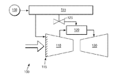
- FIG. 1 is a schematic illustrating an environment within which a known method of starting a turbomachine operates.
- a turbomachine 100 in the form of a gas turbine, includes: a compressor section 110 ; a combustion system 120 ; a fuel supply system 125 ; a turbine section 130 ; and a turbine control system 150 .
- the combustion system 120 may receive a fuel from a fuel circuit 127 of the fuel system 125 .
- Embodiments of the fuel system 125 may comprise multiple fuel circuits 127 .
- the multiple fuel circuits may include at least one of: a gas fuel circuit; a liquid fuel circuit; or an IGCC circuit, which is configured for delivering a mixed or synthetic gas fuel.
- Embodiments of the present invention may be applied to a gas turbine 100 with a fuel system 125 comprising either single or multiple fuel circuits 127 .
- the compressor section 110 includes a plurality of inlet guide vanes (IGVs) 115 and a plurality of rotating blades and stationary vanes structured to compress an ingested air, illustrated by the large arrow in FIG. 1 .
- IGVs inlet guide vanes
- the compressed air and fuel are mixed, ignited, and create a working fluid.
- the working fluid generally proceeds downstream from the combustion system 120 to the turbine section 130 .
- the turbine section 130 includes a plurality of rotating and stationary components (neither of which are illustrated) that convert the working fluid to a mechanical torque, which may be used to drive a load.
- known methods of starting-up the gas turbine 100 performs the following steps.
- the control system 150 accelerates the gas turbine 100 to a predefined purge speed. Then, the control system maintains the purge speed until a predefined timer is complete. The length of this timer is previously determined, factory set, or the like. This timer serves to ensure that sufficient airflow passes through an exhaust system (not illustrated), after which the purging process is complete.
- the control system 150 decelerates the gas turbine 100 to a predefined ignition speed.
- a valve position, of the combustion system 120 is modulated to a predefined position for ignition fuel flow, controlled under an open loop fuel flow philosophy.
- the control system 150 accelerates the gas turbine 100 to a primary operating speed, such as, but not limiting of, FSNL, using an open loop fuel and air schedules. These schedules are fixed and typically do not account for changes in gas turbine 100 performance or inlet conditions, resulting in a large variation in start up times.
- the present invention may be embodied as a method, system, or computer program product. Accordingly, the present invention may take the form of an entirely hardware embodiment, an entirely software embodiment (including firmware, resident software, micro-code, etc.) or an embodiment combining software and hardware aspects all generally referred to herein as a “circuit”, “module,” or “system”. Furthermore, the present invention may take the form of a computer program product on a computer-usable storage medium having computer-usable program code embodied in the medium.
- the terms “software” and “firmware” are interchangeable, and include any computer program stored in memory for execution by a processor, including RAM memory, ROM memory, EPROM memory, EEPROM memory, and non-volatile RAM (NVRAM) memory.
- RAM memory random access memory
- ROM memory read-only memory
- EPROM memory electrically erasable programmable read-only memory
- EEPROM memory electrically erasable programmable read-only memory
- NVRAM non-volatile RAM
- the computer-usable or computer-readable medium may be, for example but not limited to, an electronic, magnetic, optical, electromagnetic, infrared, or semiconductor system, apparatus, device, or propagation medium. More specific examples (a non exhaustive list) of the computer-readable medium would include the following: an electrical connection having one or more wires, a portable computer diskette, a hard disk, a random access memory (RAM), a read-only memory (ROM), an erasable programmable read-only memory (EPROM or Flash memory), an optical fiber, a portable compact disc read-only memory (CD-ROM), an optical storage device, a transmission media such as those supporting the Internet or an intranet, or a magnetic storage device.
- the computer-usable or computer-readable medium could even be paper or another suitable medium upon which the program is printed, as the program can be electronically captured, via, for instance, optical scanning of the paper or other medium, then compiled, interpreted, or otherwise processed in a suitable manner, if necessary, and then stored in a computer memory.
- a computer-usable or computer-readable medium may be any medium that can contain, store, communicate, propagate, or transport the program for use by or in connection with the instruction execution system, apparatus, or device.
- processor refers to central processing units, microprocessors, microcontrollers, reduced instruction set circuits (RISC), application specific integrated circuits (ASIC), logic circuits, and any other circuit or processor capable of executing the functions described herein.
- RISC reduced instruction set circuits
- ASIC application specific integrated circuits
- Computer program code for carrying out operations of the present invention may be written in an object oriented programming language such as Java7, Smalltalk or C++, or the like. However, the computer program code for carrying out operations of the present invention may also be written in conventional procedural programming languages, such as the “C” programming language, or a similar language.
- the program code may execute entirely on the user's computer, partly on the user's computer, as a stand-alone software package, partly on the user's computer and partly on a remote computer or entirely on the remote computer. In the latter scenario, the remote computer may be connected to the user's computer through a local area network (LAN) or a wide area network (WAN), or the connection may be made to an external computer (for example, through the Internet using an Internet Service Provider).
- LAN local area network
- WAN wide area network
- Internet Service Provider for example, AT&T, MCI, Sprint, EarthLink, MSN, GTE, etc.
- These computer program instructions may also be stored in a computer-readable memory. These instructions can direct a computer or other programmable data processing apparatus to function in a particular manner. The such that the instructions stored in the computer-readable memory produce an article of manufacture including instruction means which implement the function/act specified in the flowchart and/or block diagram block or blocks.
- the computer program instructions may also be loaded onto a computer or other programmable data processing apparatus. These instructions may cause a series of operational steps to be performed on the computer or other programmable apparatus to produce a computer implemented process.
- the instructions, which execute on the computer or other programmable apparatus provide steps for implementing the functions/acts specified in the flowchart and/or block diagram blocks.
- Embodiments of the present invention employ a closed loop controls philosophy, which actively determines the air-to-fuel ratio of the gas turbine 100 throughout the start-up process.
- This closed loop controls philosophy may provide the following benefits. Performing the ignition process while the gas turbine 100 is operating at the purge speed; eliminates the aforementioned coast down period. Reducing or eliminating the warm-up timer. Increasing the acceleration rate of the gas turbine 100 to the primary operating speed. These benefits may reduce the overall start-up time of the gas turbine 100 .
- the gas turbine 100 may be operated on a nearly optimal and repeatable schedule. These benefits may reduce thermal transients, possibly extending parts life; reduce variations in start-up times, and possibly increasing combustor margin.
- FIG. 2 is a schematic illustrating an environment within which an embodiment of the present invention may operate.
- the majority of the components of the gas turbine 100 discussed with FIG. 1 are the same in FIG. 2 .
- the discussion of FIG. 2 focuses on an embodiment of the present invention applied to the gas turbine 100 .
- An embodiment of the present invention may provide a modified control system 155 .
- the control system 155 may be configured with an algorithm that applies an embodiment of the present invention to the gas turbine 100 . This algorithm may determine the air-to-fuel ratio in real time.
- the control system 155 may receive operating data 160 corresponding to the air ingested by the compressor 110 and the fuel delivered by the fuel supply system 125 . This operating data 160 may also correspond to the operating characteristics of the compressor 110 and the fuel supply system 125 .
- control system may determine the air-to-fuel ratio for the ignition mode and the acceleration mode of the start-up process.
- control system 155 may modulate the IGVs 115 and/or a valve of the fuel system 125 , apportioning the air and/or fuel required to achieve or maintain the optimum air-to-fuel ratio for the specific start-up mode.
- FIGS. 3 and 4 discuss this process in further detail.
- FIG. 3 is a block diagram 300 illustrating algorithms of a control system 155 used to start-up a gas turbine 100 , in accordance with an embodiment of the present invention.
- three primary algorithms, 310 , 320 , 330 may determine, in real time, the air-to-fuel ratio at the various modes of the start-up process.
- algorithms 310 , 320 , 330 may determine the required fuel and air commands to be sent to the controllers of the IGVs 115 and the fuel system 125 allowing for optimization of the air-to-fuel ratio.
- Block 310 illustrates the algorithm that may determine the air-to-fuel ratio.
- this algorithm may receive operating data 160 relating to: the physical properties of the air ingested by the compressor 110 , the physical characteristics of the compressor 110 , the physical properties of the fuel, and the physical characteristics of the fuel supply system 125 , and the current operating parameters of the gas turbine 100 .
- the physical properties of the air may include, but are not limited to: the temperature, pressure, the humidity, and other ambient conditions.
- the physical characteristics of the compressor 110 may provide data on the cleanliness and fouling of the compressor. These physical characteristics may include, but are not limited to, a flowrate, pressure, differential pressure, and the like.
- the physical properties of the fuel may include, but are not limited to, the heating value of the fuel, the specific gravity, temperature, Wobbie Index, and the like.
- the physical characteristics of the fuel supply system 125 may relate to the accuracy of the components of the fuel supply system 160 .
- This data may include, but is not limited to, the difference between a valve reference and feedback, pressure, flowrate, and the like.
- the current operating parameters of the gas turbine 100 may include, but is not limited to, the speed and acceleration of the turbomachine.
- the algorithm of block 310 may employ a look-up table, physics based model, or the like, to determine the air-to-fuel ratio, illustrated as arrow 315 .
- Fuel command block 320 functions to determine a fuel command 325 for a valve of the fuel supply system 125 .
- Block 320 may incorporate an algorithm with a look-up table, physics based model, or the like, to determine the position command 325 after receiving the data of the air-to-fuel ratio 315 .
- Air command block 330 functions to determine an air command 335 for a valve of the IGVs 115 .
- Block 320 may incorporate an algorithm with a look-up table, physics based model, or the like, to determine the position command 325 after receiving the data of the air-to-fuel ratio 315 .
- FIGS. 4A , 4 B, collectively FIG. 4 are flowcharts illustrating a method 400 of starting a turbomachine, in accordance with an embodiment of the present invention.
- a graphical user interface may be provide, allowing an operator to navigate the steps performed by the method 400 .
- step 405 the method 400 the turbomachine may be started.
- the operator of the turbomachine may have received a request for power
- the method 400 may prompt the operator, via the GUI to select a purge speed.
- An embodiment of the present invention may calculate the time required to complete a purge cycle at a given purge speed.
- the method 400 may calculate the required purge time based on: the desired purge speed, current ambient conditions, and the size of the exhaust system. As discussed, selecting a higher purge speed may greatly reduce the startup time of the turbomachine.
- the method 400 may accelerate the turbomachine to the purge speed selected in step 410 , starting the purge cycle.
- the method 400 may be integrated with the starting system used to start the turbomachine.
- the starting system directly, or indirectly, accelerates the turbomachine to the selected purge speed.
- the method 400 may determine whether a purge cycle is complete. As discussed, the method 400 may calculate the time of the purge cycle. After this time is calculated, the method 400 may determine whether sufficient time has elapsed to complete the purge cycle. If the purge cycle is complete, then the method 400 may proceed to step 425 , otherwise the method 400 may revert to step 415 .
- the method 400 may determine the air-to-fuel ratio for the ignition process.
- embodiments of the present invention may utilize an algorithm to calculate the air-to-fuel ratio required for the ignition process.
- the algorithm may perform the following steps. Receive data on the physical properties of air ingested by the compressor section. Receive data on a physical condition of the compressor section. Receive data on a physical property of a fuel delivered to the combustion system by the fuel system. Receive data on a condition of the fuel system. Then, the algorithm determines the air-to-fuel ratio for the ignition process.
- Embodiments of the method 400 may calculate the required air-to-fuel ratio for ignition at the selected purge speed. The method 400 may compensate for the present ambient and equipment conditions; and may allow the ignition process to occur at any speed.
- the method 400 may complete the ignition process.
- the GUI may provide indication that the combustion system has flame in each combustion can of a gas turbine.
- embodiments of the present invention may not require a warm-up cycle. This may reduced the overall start-up time of the turbomachine.
- the method 400 may determine an air-to-fuel ratio for the acceleration mode.
- embodiments of the present invention may utilize an algorithm to calculate the air-to-fuel ratio required for the acceleration mode.
- the algorithm may perform the following steps. Receive data on the physical properties of air ingested by the compressor section. Receive data on a physical condition of the compressor section. Receive data on a physical property of a fuel delivered to the combustion system by the fuel system. Receive data on a condition of the fuel system. Then, the algorithm determines the required air-to-fuel ratio for the acceleration mode.
- the method 400 may utilize the aforementioned algorithm to continually determine the required air-to-fuel ratio as the turbomachine accelerates.
- the method 400 incorporates a closed-loop controls philosophy to dynamically compensate for changes in ambient conditions, inlet conditions, and the like; as previously discussed.
- the method 400 may continue to actively determine the required air-to-fuel ratio until the turbomachine reaches a primary operating speed, such as, but not limiting of, FSNL.
- a primary operating speed such as, but not limiting of, FSNL.
- the method 400 incorporates a closed-loop controls philosophy to dynamically compensate for changes in ambient conditions, inlet conditions, and the like; as previously discussed.
- embodiments of the present invention may substantially reduce the time required to start a turbomachine.
- Embodiments of the present invention may significantly reduce the start-up time, because purging, ignition, and acceleration may all be accomplished at much higher speeds due to the real time calculation of the turbine systems air fuel ratio.
Landscapes
- Engineering & Computer Science (AREA)
- Mechanical Engineering (AREA)
- General Engineering & Computer Science (AREA)
- Control Of Turbines (AREA)
- Structures Of Non-Positive Displacement Pumps (AREA)
Abstract
Embodiments of the present invention employ a closed loop controls philosophy that actively determines the air-to-fuel ratio of turbomachine throughout the start-up process. This closed loop controls philosophy provides many benefits. This philosophy performs the ignition process while the turbomachine is operating at a purge speed and eliminates the associated coast down period. Reduces or eliminates the warm-up timer. The philosophy may also increase the acceleration rate of the turbomachine to the primary operating speed. These benefits may reduce the overall start-up time of the turbomachine.
Furthermore, by actively controlling the air-to-fuel ratios during the start-up processes, the turbomachine may be operated on a nearly optimal and repeatable schedule. These benefits may reduce thermal transients, possibly extending parts life; reduce variations in start-up times, and possibly increasing combustor margin.
Description
- This application is related to commonly-assigned U.S. patent application Ser. No. 12/331,824 [GE Docket 230465-2], filed Dec. 10, 2008.
- The present invention relates generally to the operation of a turbomachine, and more particularly, to a method of reducing the start-up time of the turbomachine.
- “Fast Start” may be considered an operating mode requiring a turbomachine to export a load, capable of emissions complaint operation, within a certain time after an operator initiates a start of that turbomachine. Fluctuating energy demand is a major factor in determining when the turbomachine operates. Turbomachines are commonly idled until sufficient demand requires operation. When demand requires operation, the turbomachine performs a start-up process before exporting the desired energy (electricity, mechanical torque, steam, and the like).
- Peaking or simple cycle plants can execute Fast Starts and are then replaced by efficient generation over a longer period. Moreover, the current assignee of the application, General Electric Company, has a portfolio of combined cycle (CC) power plants (CCPP), such as, but not limited to, those disclosed in US27113562A1, entitled “Method and Apparatus for Starting Up Combined Cycle Power Systems”. In addition, U.S. Pat. No. 4,207,864, entitled “Damper”; U.S. Pat. No. 4,208,882, entitled “Startup Attemperator”; U.S. Pat. No. 4,598,551, entitled “Apparatus and Method for Controlling Steam Turbine Operating Conditions During Starting and Loading”. Also, U.S. Pat. No. 5,361,585, entitled “Steam Turbine Split Forward Flow”; U.S. Pat. No. 5,412,936, entitled “Method of Effecting Start-up of a Cold Steam Turbine System in a Combined Cycle Plant”; U.S. Pat. No. 6,626,635, entitled “System for Controlling Clearance Between Blade Tips and a Surrounding Casing in Rotating Machinery”. Reference to these commonly assigned patents and patent applications can provide further insight into the scope of the Fast Start technology and the subject matter herein.
- The start-up process of some known turbomachines typically involves a plurality modes occurring at different operating speeds. These modes include, but are not limited to: a purge, an ignition, a warm-up, and acceleration to a primary operating speed. This start-up process requires a coast down period from the purge speed to an ignition speed. This coast down period typically requires several minutes to complete. Fast Start technology requires turbomachines to quickly start and generate power.
- Therefore, there is a desire for an improved method of starting a gas turbine. The method should reduce the start-up time. This method should also reduce or eliminate the time associated with the coast down and warm-up periods. This method should also reduce the time of accelerating the turbomachine to a primary operating speed, such as, but not limiting of, full-speed-no-load (FSNL).
- In an embodiment of the present invention, a method of starting a turbomachine, the method comprising: providing a turbomachine comprising: a compressor section, a fuel system, and a combustion system; selecting a purge speed for the turbomachine; and accelerating the turbomachine to the purge speed; wherein the step of selecting the purge speed allows for reducing a start-up time of the turbomachine.
- An alternate embodiment of the present invention provides a method of starting a turbomachine, the method comprising: providing a turbomachine comprising: a compressor section, a fuel system, and a combustion system; selecting a purge speed for the turbomachine; accelerating the turbomachine to the purge speed; determining whether a purge cycle is complete; and selecting an acceleration rate for an acceleration process of the turbomachine; wherein the step of selecting the purge speed allows for reducing a start-up time of the turbomachine, increasing the possibility of the turbomachine meeting a requirement of a Fast Start operation.
- Another alternate embodiment of the present invention provides a system configured for starting a turbomachine, the system comprising: a turbomachine comprising: a compressor section, a fuel system, and a combustion system; and a control system configured for controlling a starting process of the turbomachine, wherein the control system performs the steps of: selecting a purge speed for the turbomachine; accelerating the turbomachine to the purge speed; determining an ignition air-to-fuel ratio for an ignition process associated with the combustion system; utilizing the ignition air-to-fuel ratio while performing the ignition process; selecting an acceleration rate for an acceleration process of the turbomachine; determining an acceleration air-to-fuel ratio for the acceleration process of the turbomachine; and utilizing the acceleration air-to-fuel ratio while accelerating the turbomachine to an operating speed.
-
FIG. 1 is a schematic illustrating an environment within which a known method of starting a turbomachine operates. -
FIG. 2 is a schematic illustrating an environment within which an embodiment of the present invention may operate. -
FIG. 3 is a block diagram illustrating algorithms of a control system used to start-up a turbomachine, in accordance with an embodiment of the present invention. -
FIGS. 4A , 4B, collectivelyFIG. 4 , are flowcharts illustrating a method of starting a turbomachine, in accordance with an embodiment of the present invention. - As discussed, “Fast Start” may be considered an operating mode of a powerplant machine. This mode generally requires the powerplant machine to export a load, while operating in emissions compliance, within a certain time after a start of that powerplant machine is initiated. As used herein, the term Fast Start is intended to include all such modes and equivalents thereof within the scope of this invention.
- The present invention has the technical effect of reducing the start-up time associated with starting a turbomachine. An embodiment of the present invention provides a method of starting a turbomachine, such as, but not limiting of, a gas turbine set to operate in a Fast Start mode. The gas turbine may include, but is not limited to, a heavy-duty gas turbine, an aero-derivative gas turbine, and the like. An embodiment of the method of the present invention provides a new philosophy for starting a turbomachine. Although embodiments of the present invention are described in relation to a gas turbine, application of the present invention is not limited to a gas turbine. Embodiments of the present invention may be applied to other industrial machines that may burn an ingested air with at least one fuel, not described herein.
- Detailed example embodiments are disclosed herein. However, specific structural and functional details disclosed herein are merely representative for purposes of describing example embodiments. Example embodiments may, however, be embodied in many alternate forms, and should not be construed as limited to only the embodiments set forth herein.
- Accordingly, while example embodiments are capable of various modifications and alternative forms, embodiments thereof are illustrated by way of example in the drawings and will herein be described in detail. It should be understood, however, that there is no intent to limit example embodiments to the particular forms disclosed, but to the contrary, example embodiments are to cover all modifications, equivalents, and alternatives falling within the scope of example embodiments.
- It will be understood that, although the terms first, second, etc. may be used herein to describe various elements, these elements should not be limited by these terms. These terms are only used to distinguish one element from another. For example, a first element could be termed a second element, and, similarly, a second element could be termed a first element, without departing from the scope of example embodiments. As used herein, the term “and/or” includes any, and all, combinations of one or more of the associated listed items.
- The terminology used herein is for describing particular embodiments only and is not intended to be limiting of example embodiments. As used herein, the singular forms “a”, “an” and “the” are intended to include the plural forms as well, unless the context clearly indicates otherwise. It will be further understood that the terms “comprises”, “comprising”, “includes” and/or “including”, when used herein, specify the presence of stated features, integers, steps, operations, elements, and/or components, but do not preclude the presence or addition of one or more other features, integers, steps, operations, elements, components, and/or groups thereof.
- It should also be noted that in some alternative implementations, the functions/acts noted might occur out of the order noted in the FIGS. Two successive FIGS., for example, may be executed substantially concurrently or may sometimes be executed in the reverse order, depending upon the functionality/operations involved.
- Referring now to the FIGS., where the various numbers represent like parts throughout the several views.
FIG. 1 is a schematic illustrating an environment within which a known method of starting a turbomachine operates. InFIG. 1 , aturbomachine 100, in the form of a gas turbine, includes: acompressor section 110; acombustion system 120; afuel supply system 125; aturbine section 130; and aturbine control system 150. Thecombustion system 120 may receive a fuel from afuel circuit 127 of thefuel system 125. Embodiments of thefuel system 125 may comprisemultiple fuel circuits 127. Here, the multiple fuel circuits may include at least one of: a gas fuel circuit; a liquid fuel circuit; or an IGCC circuit, which is configured for delivering a mixed or synthetic gas fuel. Embodiments of the present invention may be applied to agas turbine 100 with afuel system 125 comprising either single ormultiple fuel circuits 127. - Generally, the
compressor section 110 includes a plurality of inlet guide vanes (IGVs) 115 and a plurality of rotating blades and stationary vanes structured to compress an ingested air, illustrated by the large arrow inFIG. 1 . Within thecombustion system 120, the compressed air and fuel are mixed, ignited, and create a working fluid. - The working fluid generally proceeds downstream from the
combustion system 120 to theturbine section 130. Theturbine section 130 includes a plurality of rotating and stationary components (neither of which are illustrated) that convert the working fluid to a mechanical torque, which may be used to drive a load. - Operationally, known methods of starting-up the
gas turbine 100 performs the following steps. Thecontrol system 150 accelerates thegas turbine 100 to a predefined purge speed. Then, the control system maintains the purge speed until a predefined timer is complete. The length of this timer is previously determined, factory set, or the like. This timer serves to ensure that sufficient airflow passes through an exhaust system (not illustrated), after which the purging process is complete. - After the purge is complete, the
control system 150 decelerates thegas turbine 100 to a predefined ignition speed. At this ignition speed, a valve position, of thecombustion system 120, is modulated to a predefined position for ignition fuel flow, controlled under an open loop fuel flow philosophy. After ignition and a pre-defined warm-up timer expires, thecontrol system 150 accelerates thegas turbine 100 to a primary operating speed, such as, but not limiting of, FSNL, using an open loop fuel and air schedules. These schedules are fixed and typically do not account for changes ingas turbine 100 performance or inlet conditions, resulting in a large variation in start up times. - As will be appreciated, the present invention may be embodied as a method, system, or computer program product. Accordingly, the present invention may take the form of an entirely hardware embodiment, an entirely software embodiment (including firmware, resident software, micro-code, etc.) or an embodiment combining software and hardware aspects all generally referred to herein as a “circuit”, “module,” or “system”. Furthermore, the present invention may take the form of a computer program product on a computer-usable storage medium having computer-usable program code embodied in the medium. As used herein, the terms “software” and “firmware” are interchangeable, and include any computer program stored in memory for execution by a processor, including RAM memory, ROM memory, EPROM memory, EEPROM memory, and non-volatile RAM (NVRAM) memory. The above memory types are exemplary only, and are thus not limiting as to the types of memory usable for storage of a computer program.
- Any suitable computer readable medium may be utilized. The computer-usable or computer-readable medium may be, for example but not limited to, an electronic, magnetic, optical, electromagnetic, infrared, or semiconductor system, apparatus, device, or propagation medium. More specific examples (a non exhaustive list) of the computer-readable medium would include the following: an electrical connection having one or more wires, a portable computer diskette, a hard disk, a random access memory (RAM), a read-only memory (ROM), an erasable programmable read-only memory (EPROM or Flash memory), an optical fiber, a portable compact disc read-only memory (CD-ROM), an optical storage device, a transmission media such as those supporting the Internet or an intranet, or a magnetic storage device. Note that the computer-usable or computer-readable medium could even be paper or another suitable medium upon which the program is printed, as the program can be electronically captured, via, for instance, optical scanning of the paper or other medium, then compiled, interpreted, or otherwise processed in a suitable manner, if necessary, and then stored in a computer memory. In the context of this document, a computer-usable or computer-readable medium may be any medium that can contain, store, communicate, propagate, or transport the program for use by or in connection with the instruction execution system, apparatus, or device.
- The term processor, as used herein, refers to central processing units, microprocessors, microcontrollers, reduced instruction set circuits (RISC), application specific integrated circuits (ASIC), logic circuits, and any other circuit or processor capable of executing the functions described herein.
- Computer program code for carrying out operations of the present invention may be written in an object oriented programming language such as Java7, Smalltalk or C++, or the like. However, the computer program code for carrying out operations of the present invention may also be written in conventional procedural programming languages, such as the “C” programming language, or a similar language. The program code may execute entirely on the user's computer, partly on the user's computer, as a stand-alone software package, partly on the user's computer and partly on a remote computer or entirely on the remote computer. In the latter scenario, the remote computer may be connected to the user's computer through a local area network (LAN) or a wide area network (WAN), or the connection may be made to an external computer (for example, through the Internet using an Internet Service Provider).
- The present invention is described below with reference to flowchart illustrations and/or block diagrams of methods, apparatuses (systems) and computer program products according to embodiments of the invention. It will be understood that each block of the flowchart illustrations and/or block diagrams, and combinations of blocks in the flowchart illustrations and/or block diagrams, can be implemented by computer program instructions. These computer program instructions may be provided to a processor of a public purpose computer, special purpose computer, or other programmable data processing apparatus to produce a machine, such that the instructions, which execute via the processor of the computer or other programmable data processing apparatus, create means for implementing the functions/acts specified in the flowchart and/or block diagram block or blocks.
- These computer program instructions may also be stored in a computer-readable memory. These instructions can direct a computer or other programmable data processing apparatus to function in a particular manner. The such that the instructions stored in the computer-readable memory produce an article of manufacture including instruction means which implement the function/act specified in the flowchart and/or block diagram block or blocks. The computer program instructions may also be loaded onto a computer or other programmable data processing apparatus. These instructions may cause a series of operational steps to be performed on the computer or other programmable apparatus to produce a computer implemented process. Here, the instructions, which execute on the computer or other programmable apparatus, provide steps for implementing the functions/acts specified in the flowchart and/or block diagram blocks.
- Embodiments of the present invention employ a closed loop controls philosophy, which actively determines the air-to-fuel ratio of the
gas turbine 100 throughout the start-up process. This closed loop controls philosophy may provide the following benefits. Performing the ignition process while thegas turbine 100 is operating at the purge speed; eliminates the aforementioned coast down period. Reducing or eliminating the warm-up timer. Increasing the acceleration rate of thegas turbine 100 to the primary operating speed. These benefits may reduce the overall start-up time of thegas turbine 100. Furthermore, by actively controlling the air-to-fuel ratios during the start-up processes, thegas turbine 100 may be operated on a nearly optimal and repeatable schedule. These benefits may reduce thermal transients, possibly extending parts life; reduce variations in start-up times, and possibly increasing combustor margin. - Referring again to the Figures,
FIG. 2 is a schematic illustrating an environment within which an embodiment of the present invention may operate. The majority of the components of thegas turbine 100 discussed withFIG. 1 , are the same inFIG. 2 . The discussion ofFIG. 2 focuses on an embodiment of the present invention applied to thegas turbine 100. An embodiment of the present invention may provide a modifiedcontrol system 155. - The
control system 155 may be configured with an algorithm that applies an embodiment of the present invention to thegas turbine 100. This algorithm may determine the air-to-fuel ratio in real time. Here, thecontrol system 155 may receive operatingdata 160 corresponding to the air ingested by thecompressor 110 and the fuel delivered by thefuel supply system 125. This operatingdata 160 may also correspond to the operating characteristics of thecompressor 110 and thefuel supply system 125. - After receiving the operating data, the control system may determine the air-to-fuel ratio for the ignition mode and the acceleration mode of the start-up process. Next, the
control system 155 may modulate theIGVs 115 and/or a valve of thefuel system 125, apportioning the air and/or fuel required to achieve or maintain the optimum air-to-fuel ratio for the specific start-up mode.FIGS. 3 and 4 discuss this process in further detail. -
FIG. 3 is a block diagram 300 illustrating algorithms of acontrol system 155 used to start-up agas turbine 100, in accordance with an embodiment of the present invention. In an embodiment of the present invention, three primary algorithms, 310, 320, 330 may determine, in real time, the air-to-fuel ratio at the various modes of the start-up process. Next,algorithms IGVs 115 and thefuel system 125 allowing for optimization of the air-to-fuel ratio. -
Block 310 illustrates the algorithm that may determine the air-to-fuel ratio. As discussed this algorithm may receive operatingdata 160 relating to: the physical properties of the air ingested by thecompressor 110, the physical characteristics of thecompressor 110, the physical properties of the fuel, and the physical characteristics of thefuel supply system 125, and the current operating parameters of thegas turbine 100. The physical properties of the air may include, but are not limited to: the temperature, pressure, the humidity, and other ambient conditions. The physical characteristics of thecompressor 110 may provide data on the cleanliness and fouling of the compressor. These physical characteristics may include, but are not limited to, a flowrate, pressure, differential pressure, and the like. The physical properties of the fuel may include, but are not limited to, the heating value of the fuel, the specific gravity, temperature, Wobbie Index, and the like. The physical characteristics of thefuel supply system 125 may relate to the accuracy of the components of thefuel supply system 160. This data may include, but is not limited to, the difference between a valve reference and feedback, pressure, flowrate, and the like. The current operating parameters of thegas turbine 100 may include, but is not limited to, the speed and acceleration of the turbomachine. After receiving thedata 160, the algorithm ofblock 310 may employ a look-up table, physics based model, or the like, to determine the air-to-fuel ratio, illustrated asarrow 315. -
Fuel command block 320 functions to determine afuel command 325 for a valve of thefuel supply system 125.Block 320 may incorporate an algorithm with a look-up table, physics based model, or the like, to determine theposition command 325 after receiving the data of the air-to-fuel ratio 315. -
Air command block 330 functions to determine anair command 335 for a valve of theIGVs 115.Block 320 may incorporate an algorithm with a look-up table, physics based model, or the like, to determine theposition command 325 after receiving the data of the air-to-fuel ratio 315. -
FIGS. 4A , 4B, collectivelyFIG. 4 , are flowcharts illustrating amethod 400 of starting a turbomachine, in accordance with an embodiment of the present invention. In an embodiment of the present invention, a graphical user interface (GUI) may be provide, allowing an operator to navigate the steps performed by themethod 400. - In
step 405, themethod 400 the turbomachine may be started. Here, the operator of the turbomachine may have received a request for power - In
step 410, themethod 400 may prompt the operator, via the GUI to select a purge speed. An embodiment of the present invention may calculate the time required to complete a purge cycle at a given purge speed. Here, themethod 400 may calculate the required purge time based on: the desired purge speed, current ambient conditions, and the size of the exhaust system. As discussed, selecting a higher purge speed may greatly reduce the startup time of the turbomachine. - In
step 415, themethod 400 may accelerate the turbomachine to the purge speed selected instep 410, starting the purge cycle. In an embodiment of the present invention, themethod 400 may be integrated with the starting system used to start the turbomachine. Here, the starting system directly, or indirectly, accelerates the turbomachine to the selected purge speed. - In
step 420, themethod 400 may determine whether a purge cycle is complete. As discussed, themethod 400 may calculate the time of the purge cycle. After this time is calculated, themethod 400 may determine whether sufficient time has elapsed to complete the purge cycle. If the purge cycle is complete, then themethod 400 may proceed to step 425, otherwise themethod 400 may revert to step 415. - In
step 425, themethod 400 may determine the air-to-fuel ratio for the ignition process. As described, embodiments of the present invention may utilize an algorithm to calculate the air-to-fuel ratio required for the ignition process. For example, but not limiting of, the algorithm may perform the following steps. Receive data on the physical properties of air ingested by the compressor section. Receive data on a physical condition of the compressor section. Receive data on a physical property of a fuel delivered to the combustion system by the fuel system. Receive data on a condition of the fuel system. Then, the algorithm determines the air-to-fuel ratio for the ignition process. Embodiments of themethod 400 may calculate the required air-to-fuel ratio for ignition at the selected purge speed. Themethod 400 may compensate for the present ambient and equipment conditions; and may allow the ignition process to occur at any speed. - In
step 430, themethod 400 may complete the ignition process. Here, for example, but not limiting of, the GUI may provide indication that the combustion system has flame in each combustion can of a gas turbine. As discussed, embodiments of the present invention may not require a warm-up cycle. This may reduced the overall start-up time of the turbomachine. - In
step 440, themethod 400 may determine an air-to-fuel ratio for the acceleration mode. As described, embodiments of the present invention may utilize an algorithm to calculate the air-to-fuel ratio required for the acceleration mode. For example, but not limiting of, the algorithm may perform the following steps. Receive data on the physical properties of air ingested by the compressor section. Receive data on a physical condition of the compressor section. Receive data on a physical property of a fuel delivered to the combustion system by the fuel system. Receive data on a condition of the fuel system. Then, the algorithm determines the required air-to-fuel ratio for the acceleration mode. - In
step 445, themethod 400 may utilize the aforementioned algorithm to continually determine the required air-to-fuel ratio as the turbomachine accelerates. Here, themethod 400 incorporates a closed-loop controls philosophy to dynamically compensate for changes in ambient conditions, inlet conditions, and the like; as previously discussed. - In
step 450, themethod 400 may continue to actively determine the required air-to-fuel ratio until the turbomachine reaches a primary operating speed, such as, but not limiting of, FSNL. As withstep 445, themethod 400 incorporates a closed-loop controls philosophy to dynamically compensate for changes in ambient conditions, inlet conditions, and the like; as previously discussed. - As discussed, embodiments of the present invention may substantially reduce the time required to start a turbomachine. Embodiments of the present invention may significantly reduce the start-up time, because purging, ignition, and acceleration may all be accomplished at much higher speeds due to the real time calculation of the turbine systems air fuel ratio.
- As one of ordinary skill in the art will appreciate, the many varying features and configurations described above in relation to the several exemplary embodiments may be further selectively applied to form the other possible embodiments of the present invention. Those in the art will further understand that all possible iterations of the present invention are not provided or discussed in detail, even though all combinations and possible embodiments embraced by the several claims below or otherwise are intended to be part of the instant application. In addition, from the above description of several exemplary embodiments of the invention, those skilled in the art will perceive improvements, changes, and modifications. Such improvements, changes, and modifications within the skill of the art are also intended to be covered by the appended claims. Further, it should be apparent that the foregoing relates only to the described embodiments of the present application and that numerous changes and modifications may be made herein without departing from the spirit and scope of the application as defined by the following claims and the equivalents thereof.
Claims (20)
1. A method of starting a turbomachine, the method comprising:
providing a turbomachine comprising: a compressor section, a fuel system, and a combustion system;
selecting a purge speed for the turbomachine; and
accelerating the turbomachine to the purge speed;
wherein the step of selecting the purge speed allows for reducing a start-up time of the turbomachine.
2. The method of claim 1 further comprising the step of determining whether a purge cycle is complete.
3. The method of claim 2 further comprising the step of determining an air-to-fuel ratio for an ignition process of the combustion system.
4. The method of claim 3 , wherein the step of determining the air-to-fuel ratio of the ignition process comprises the steps of:
receiving data on an ambient condition of air ingested by the compressor section;
receiving data on a physical condition of the compressor section;
receiving data on a physical property of at least one fuel delivered to the combustion system by the fuel system;
receiving data on a condition of the fuel system; and
determining the air-to-fuel ratio for the ignition process of the combustion system.
5. The method of claim 4 further comprising the step of controlling a fuel flow of the fuel system to achieve the air-to-fuel ratio for the ignition process.
6. The method of claim of claim 5 further comprising the step of determining whether the ignition process is complete.
7. The method of claim 2 further comprising the step of selecting an acceleration rate for an acceleration process of the turbomachine.
8. The method of claim 7 further comprising the step of determining an air-to-fuel ratio for the acceleration rate of the turbomachine.
9. The method of claim 8 , wherein the step of determining the air-to-fuel ratio for the acceleration process of the turbomachine comprises the steps of:
receiving data on an ambient condition of air ingested by the compressor section;
receiving data on a physical condition of the compressor section;
receiving data on a physical property of at least one fuel delivered to the combustion system by the fuel system;
receiving data on a condition of the fuel system; and
determining the air-to-fuel ratio for the acceleration process of the turbomachine.
10. The method of claim 9 further comprising the step of controlling a fuel flow of the fuel system to achieve the air-to-fuel ratio for the acceleration process to maintain the acceleration rate.
11. A method of starting a turbomachine, the method comprising:
providing a turbomachine comprising: a compressor section, a fuel system, and a combustion system;
selecting a purge speed for the turbomachine;
accelerating the turbomachine to the purge speed;
determining whether a purge cycle is complete; and
selecting an acceleration rate for an acceleration process of the turbomachine;
wherein the step of selecting the purge speed allows for reducing a start-up time of the turbomachine, increasing the possibility of the turbomachine meeting a requirement of a Fast Start operation.
12. The method of claim 11 , determining an air-to-fuel ratio for an ignition process of the combustion system.
13. The method of claim of claim 12 further comprising the step of determining whether the ignition process is complete.
14. The method of claim 13 further comprising the step of determining an air-to-fuel ratio for the acceleration rate of the turbomachine.
15. The method of claim 14 further comprising the steps of controlling a fuel flow of the fuel system to achieve the air-to-fuel ratio for the acceleration process to maintain the acceleration rate; and accelerating the turbomachine to an operating speed at the acceleration rate.
16. A system configured for starting a turbomachine, the system comprising:
a turbomachine comprising: a compressor section, a fuel system, and a combustion system; and
a control system configured for controlling a starting process of the turbomachine, wherein the control system performs the steps of:
selecting a purge speed for the turbomachine;
accelerating the turbomachine to the purge speed;
determining an ignition air-to-fuel ratio for an ignition process associated with the combustion system;
utilizing the ignition air-to-fuel ratio while performing the ignition process;
selecting an acceleration rate for an acceleration process of the turbomachine;
determining an acceleration air-to-fuel ratio for the acceleration process of the turbomachine; and
utilizing the acceleration air-to-fuel ratio while accelerating the turbomachine to an operating speed.
17. The system of claim 16 , wherein the control system determines the ignition air-to-fuel ratio by performing the steps of:
receiving data on an ambient condition of air ingested by the compressor section;
receiving data on a physical condition of the compressor section;
receiving data on a physical property of at least one fuel delivered to the combustion system by the fuel system;
receiving data on a condition of the fuel system; and
determining the air-to-fuel ratio for the ignition process.
18. The system of claim 16 , wherein the control system performs the steps of:
receiving data on an ambient condition of air ingested by the compressor section;
receiving data on a physical condition of the compressor section;
receiving data on a physical property of at least one fuel delivered to the combustion system by the fuel system;
receiving data on a condition of the fuel system; and
determining the air-to-fuel ratio for the acceleration process.
19. The system of claim 16 , wherein the fuel system comprises multiple fuel circuits.
20. The system of claim 19 , wherein the multiple fuel circuits comprise at least one of: a gas fuel circuit, a liquid fuel circuit, or an IGCC circuit.
Priority Applications (4)
| Application Number | Priority Date | Filing Date | Title |
|---|---|---|---|
| US12/646,101 US20110146292A1 (en) | 2009-12-23 | 2009-12-23 | Method for starting a turbomachine |
| EP10193955A EP2339127A2 (en) | 2009-12-23 | 2010-12-07 | Method for starting a turbomachine |
| JP2010280122A JP2011132954A (en) | 2009-12-23 | 2010-12-16 | Method for starting turbomachine |
| CN2010106199947A CN102108902A (en) | 2009-12-23 | 2010-12-23 | Method for starting a turbomachine |
Applications Claiming Priority (1)
| Application Number | Priority Date | Filing Date | Title |
|---|---|---|---|
| US12/646,101 US20110146292A1 (en) | 2009-12-23 | 2009-12-23 | Method for starting a turbomachine |
Publications (1)
| Publication Number | Publication Date |
|---|---|
| US20110146292A1 true US20110146292A1 (en) | 2011-06-23 |
Family
ID=43614177
Family Applications (1)
| Application Number | Title | Priority Date | Filing Date |
|---|---|---|---|
| US12/646,101 Abandoned US20110146292A1 (en) | 2009-12-23 | 2009-12-23 | Method for starting a turbomachine |
Country Status (4)
| Country | Link |
|---|---|
| US (1) | US20110146292A1 (en) |
| EP (1) | EP2339127A2 (en) |
| JP (1) | JP2011132954A (en) |
| CN (1) | CN102108902A (en) |
Cited By (1)
| Publication number | Priority date | Publication date | Assignee | Title |
|---|---|---|---|---|
| US20130167550A1 (en) * | 2012-01-03 | 2013-07-04 | General Electric Company | Method for meeting a purge flow requirement for a power plant and a power plant having a purge control system |
Families Citing this family (5)
| Publication number | Priority date | Publication date | Assignee | Title |
|---|---|---|---|---|
| AU2012354937A1 (en) * | 2011-12-22 | 2014-07-10 | Kawasaki Jukogyo Kabushiki Kaisha | Gas turbine engine and method for starting same |
| JP5931556B2 (en) * | 2012-04-13 | 2016-06-08 | 三菱日立パワーシステムズ株式会社 | Gas turbine control device, gas turbine, and gas turbine control method |
| US20180010617A1 (en) * | 2016-07-11 | 2018-01-11 | General Electric Company | Gas turbine compressor passive clearance control |
| US10641179B2 (en) * | 2016-11-07 | 2020-05-05 | General Electric Company | System and method for starting gas turbine engines |
| US10352189B2 (en) * | 2017-05-10 | 2019-07-16 | Pratt & Whitney Canada Corp. | Method and system for setting an acceleration schedule for engine start |
Citations (12)
| Publication number | Priority date | Publication date | Assignee | Title |
|---|---|---|---|---|
| US4134258A (en) * | 1974-06-10 | 1979-01-16 | Nippondenso Co., Ltd. | Fuel control system |
| US4207864A (en) * | 1978-06-08 | 1980-06-17 | General Electric Company | Damper |
| US4208882A (en) * | 1977-12-15 | 1980-06-24 | General Electric Company | Start-up attemperator |
| US4598551A (en) * | 1985-10-25 | 1986-07-08 | General Electric Company | Apparatus and method for controlling steam turbine operating conditions during starting and loading |
| US5203160A (en) * | 1990-10-18 | 1993-04-20 | Kabushiki Kaisha Toshiba | Combined generating plant and its start-up control device and start-up control method |
| US5361585A (en) * | 1993-06-25 | 1994-11-08 | General Electric Company | Steam turbine split forward flow |
| US5412936A (en) * | 1992-12-30 | 1995-05-09 | General Electric Co. | Method of effecting start-up of a cold steam turbine system in a combined cycle plant |
| US5966925A (en) * | 1996-04-26 | 1999-10-19 | Kabushiki Kaisha Toshiba | Gas turbine power plant control for starting and stopping |
| US6626635B1 (en) * | 1998-09-30 | 2003-09-30 | General Electric Company | System for controlling clearance between blade tips and a surrounding casing in rotating machinery |
| US6722135B2 (en) * | 2002-01-29 | 2004-04-20 | General Electric Company | Performance enhanced control of DLN gas turbines |
| US20070055392A1 (en) * | 2005-09-06 | 2007-03-08 | D Amato Fernando J | Method and system for model predictive control of a power plant |
| US20070113562A1 (en) * | 2005-11-18 | 2007-05-24 | General Electric Company | Methods and apparatus for starting up combined cycle power systems |
-
2009
- 2009-12-23 US US12/646,101 patent/US20110146292A1/en not_active Abandoned
-
2010
- 2010-12-07 EP EP10193955A patent/EP2339127A2/en not_active Withdrawn
- 2010-12-16 JP JP2010280122A patent/JP2011132954A/en not_active Withdrawn
- 2010-12-23 CN CN2010106199947A patent/CN102108902A/en active Pending
Patent Citations (12)
| Publication number | Priority date | Publication date | Assignee | Title |
|---|---|---|---|---|
| US4134258A (en) * | 1974-06-10 | 1979-01-16 | Nippondenso Co., Ltd. | Fuel control system |
| US4208882A (en) * | 1977-12-15 | 1980-06-24 | General Electric Company | Start-up attemperator |
| US4207864A (en) * | 1978-06-08 | 1980-06-17 | General Electric Company | Damper |
| US4598551A (en) * | 1985-10-25 | 1986-07-08 | General Electric Company | Apparatus and method for controlling steam turbine operating conditions during starting and loading |
| US5203160A (en) * | 1990-10-18 | 1993-04-20 | Kabushiki Kaisha Toshiba | Combined generating plant and its start-up control device and start-up control method |
| US5412936A (en) * | 1992-12-30 | 1995-05-09 | General Electric Co. | Method of effecting start-up of a cold steam turbine system in a combined cycle plant |
| US5361585A (en) * | 1993-06-25 | 1994-11-08 | General Electric Company | Steam turbine split forward flow |
| US5966925A (en) * | 1996-04-26 | 1999-10-19 | Kabushiki Kaisha Toshiba | Gas turbine power plant control for starting and stopping |
| US6626635B1 (en) * | 1998-09-30 | 2003-09-30 | General Electric Company | System for controlling clearance between blade tips and a surrounding casing in rotating machinery |
| US6722135B2 (en) * | 2002-01-29 | 2004-04-20 | General Electric Company | Performance enhanced control of DLN gas turbines |
| US20070055392A1 (en) * | 2005-09-06 | 2007-03-08 | D Amato Fernando J | Method and system for model predictive control of a power plant |
| US20070113562A1 (en) * | 2005-11-18 | 2007-05-24 | General Electric Company | Methods and apparatus for starting up combined cycle power systems |
Cited By (2)
| Publication number | Priority date | Publication date | Assignee | Title |
|---|---|---|---|---|
| US20130167550A1 (en) * | 2012-01-03 | 2013-07-04 | General Electric Company | Method for meeting a purge flow requirement for a power plant and a power plant having a purge control system |
| US8844295B2 (en) * | 2012-01-03 | 2014-09-30 | General Electric Company | Method for meeting a purge flow requirement for a power plant and a power plant having a purge control system |
Also Published As
| Publication number | Publication date |
|---|---|
| CN102108902A (en) | 2011-06-29 |
| EP2339127A2 (en) | 2011-06-29 |
| JP2011132954A (en) | 2011-07-07 |
Similar Documents
| Publication | Publication Date | Title |
|---|---|---|
| US8555653B2 (en) | Method for starting a turbomachine | |
| US7915868B1 (en) | Method of synchronizing a turbomachine generator to an electric grid | |
| JP6877908B2 (en) | A system for controlling the coolant supply to the exhaust gas | |
| US9523313B2 (en) | System and method for loading a combined cycle power plant | |
| US10161317B2 (en) | Gas-turbine control device, gas turbine, and gas-turbine control method | |
| US20110146288A1 (en) | Method of controlling a fuel flow to a turbomachine | |
| US20110146292A1 (en) | Method for starting a turbomachine | |
| US9828887B2 (en) | Power generation system having compressor creating excess air flow and turbo-expander to increase turbine exhaust gas mass flow | |
| JP2012036889A (en) | Method for compensating for combustion efficiency in fuel control system | |
| EP3064746B1 (en) | Systems and methods for turbine system operation in low ambient temperatures | |
| US20160273408A1 (en) | Power generation system having compressor creating excess air flow and eductor for augmenting same | |
| US9822670B2 (en) | Power generation system having compressor creating excess air flow and turbo-expander for cooling inlet air | |
| US10954824B2 (en) | Systems and methods for controlling drum levels using flow | |
| JP6827744B2 (en) | Transient emission temperature control of turbine system | |
| EP2175120B1 (en) | Method and system for operating a turbomachine | |
| EP4087083A1 (en) | Coordinated combined cycle power plant response for block loading in grid restoration | |
| CN115751289B (en) | A method and device for full-process control of boiler feedwater based on automatic start-stop control. | |
| JP2025538354A (en) | System and method for model-based control of a gas turbine system considering fluid injection | |
| JP6246897B2 (en) | Method and gas turbine for reducing CO emissions of a gas turbine | |
| EP3301268A1 (en) | Power plant control in coordination with further energy sources, like renewable energy |
Legal Events
| Date | Code | Title | Description |
|---|---|---|---|
| AS | Assignment |
Owner name: GENERAL ELECTRIC COMPANY, NEW YORK Free format text: ASSIGNMENT OF ASSIGNORS INTEREST;ASSIGNORS:GRANT, MATTHEW B.;LAW, JOSEPH R.;REEL/FRAME:023695/0357 Effective date: 20091210 |
|
| STCB | Information on status: application discontinuation |
Free format text: ABANDONED -- FAILURE TO RESPOND TO AN OFFICE ACTION |