US20110097592A1 - Multi-layer structure including a buffer layer - Google Patents
Multi-layer structure including a buffer layer Download PDFInfo
- Publication number
- US20110097592A1 US20110097592A1 US12/884,883 US88488310A US2011097592A1 US 20110097592 A1 US20110097592 A1 US 20110097592A1 US 88488310 A US88488310 A US 88488310A US 2011097592 A1 US2011097592 A1 US 2011097592A1
- Authority
- US
- United States
- Prior art keywords
- layer
- layer structure
- substrate
- buffer layer
- bonding
- Prior art date
- Legal status (The legal status is an assumption and is not a legal conclusion. Google has not performed a legal analysis and makes no representation as to the accuracy of the status listed.)
- Abandoned
Links
Images


Classifications
-
- B—PERFORMING OPERATIONS; TRANSPORTING
- B29—WORKING OF PLASTICS; WORKING OF SUBSTANCES IN A PLASTIC STATE IN GENERAL
- B29C—SHAPING OR JOINING OF PLASTICS; SHAPING OF MATERIAL IN A PLASTIC STATE, NOT OTHERWISE PROVIDED FOR; AFTER-TREATMENT OF THE SHAPED PRODUCTS, e.g. REPAIRING
- B29C45/00—Injection moulding, i.e. forcing the required volume of moulding material through a nozzle into a closed mould; Apparatus therefor
- B29C45/14—Injection moulding, i.e. forcing the required volume of moulding material through a nozzle into a closed mould; Apparatus therefor incorporating preformed parts or layers, e.g. injection moulding around inserts or for coating articles
- B29C45/14778—Injection moulding, i.e. forcing the required volume of moulding material through a nozzle into a closed mould; Apparatus therefor incorporating preformed parts or layers, e.g. injection moulding around inserts or for coating articles the article consisting of a material with particular properties, e.g. porous, brittle
- B29C45/14811—Multilayered articles
-
- B—PERFORMING OPERATIONS; TRANSPORTING
- B32—LAYERED PRODUCTS
- B32B—LAYERED PRODUCTS, i.e. PRODUCTS BUILT-UP OF STRATA OF FLAT OR NON-FLAT, e.g. CELLULAR OR HONEYCOMB, FORM
- B32B21/00—Layered products comprising a layer of wood, e.g. wood board, veneer, wood particle board
- B32B21/04—Layered products comprising a layer of wood, e.g. wood board, veneer, wood particle board comprising wood as the main or only constituent of a layer, which is next to another layer of the same or of a different material
- B32B21/08—Layered products comprising a layer of wood, e.g. wood board, veneer, wood particle board comprising wood as the main or only constituent of a layer, which is next to another layer of the same or of a different material of synthetic resin
-
- B—PERFORMING OPERATIONS; TRANSPORTING
- B32—LAYERED PRODUCTS
- B32B—LAYERED PRODUCTS, i.e. PRODUCTS BUILT-UP OF STRATA OF FLAT OR NON-FLAT, e.g. CELLULAR OR HONEYCOMB, FORM
- B32B27/00—Layered products comprising a layer of synthetic resin
- B32B27/06—Layered products comprising a layer of synthetic resin as the main or only constituent of a layer, which is next to another layer of the same or of a different material
- B32B27/08—Layered products comprising a layer of synthetic resin as the main or only constituent of a layer, which is next to another layer of the same or of a different material of synthetic resin
-
- B—PERFORMING OPERATIONS; TRANSPORTING
- B32—LAYERED PRODUCTS
- B32B—LAYERED PRODUCTS, i.e. PRODUCTS BUILT-UP OF STRATA OF FLAT OR NON-FLAT, e.g. CELLULAR OR HONEYCOMB, FORM
- B32B27/00—Layered products comprising a layer of synthetic resin
- B32B27/30—Layered products comprising a layer of synthetic resin comprising vinyl (co)polymers; comprising acrylic (co)polymers
- B32B27/302—Layered products comprising a layer of synthetic resin comprising vinyl (co)polymers; comprising acrylic (co)polymers comprising aromatic vinyl (co)polymers, e.g. styrenic (co)polymers
-
- B—PERFORMING OPERATIONS; TRANSPORTING
- B32—LAYERED PRODUCTS
- B32B—LAYERED PRODUCTS, i.e. PRODUCTS BUILT-UP OF STRATA OF FLAT OR NON-FLAT, e.g. CELLULAR OR HONEYCOMB, FORM
- B32B27/00—Layered products comprising a layer of synthetic resin
- B32B27/30—Layered products comprising a layer of synthetic resin comprising vinyl (co)polymers; comprising acrylic (co)polymers
- B32B27/304—Layered products comprising a layer of synthetic resin comprising vinyl (co)polymers; comprising acrylic (co)polymers comprising vinyl halide (co)polymers, e.g. PVC, PVDC, PVF, PVDF
-
- B—PERFORMING OPERATIONS; TRANSPORTING
- B32—LAYERED PRODUCTS
- B32B—LAYERED PRODUCTS, i.e. PRODUCTS BUILT-UP OF STRATA OF FLAT OR NON-FLAT, e.g. CELLULAR OR HONEYCOMB, FORM
- B32B27/00—Layered products comprising a layer of synthetic resin
- B32B27/30—Layered products comprising a layer of synthetic resin comprising vinyl (co)polymers; comprising acrylic (co)polymers
- B32B27/308—Layered products comprising a layer of synthetic resin comprising vinyl (co)polymers; comprising acrylic (co)polymers comprising acrylic (co)polymers
-
- B—PERFORMING OPERATIONS; TRANSPORTING
- B32—LAYERED PRODUCTS
- B32B—LAYERED PRODUCTS, i.e. PRODUCTS BUILT-UP OF STRATA OF FLAT OR NON-FLAT, e.g. CELLULAR OR HONEYCOMB, FORM
- B32B27/00—Layered products comprising a layer of synthetic resin
- B32B27/32—Layered products comprising a layer of synthetic resin comprising polyolefins
-
- B—PERFORMING OPERATIONS; TRANSPORTING
- B32—LAYERED PRODUCTS
- B32B—LAYERED PRODUCTS, i.e. PRODUCTS BUILT-UP OF STRATA OF FLAT OR NON-FLAT, e.g. CELLULAR OR HONEYCOMB, FORM
- B32B27/00—Layered products comprising a layer of synthetic resin
- B32B27/34—Layered products comprising a layer of synthetic resin comprising polyamides
-
- B—PERFORMING OPERATIONS; TRANSPORTING
- B32—LAYERED PRODUCTS
- B32B—LAYERED PRODUCTS, i.e. PRODUCTS BUILT-UP OF STRATA OF FLAT OR NON-FLAT, e.g. CELLULAR OR HONEYCOMB, FORM
- B32B27/00—Layered products comprising a layer of synthetic resin
- B32B27/36—Layered products comprising a layer of synthetic resin comprising polyesters
- B32B27/365—Layered products comprising a layer of synthetic resin comprising polyesters comprising polycarbonates
-
- B—PERFORMING OPERATIONS; TRANSPORTING
- B32—LAYERED PRODUCTS
- B32B—LAYERED PRODUCTS, i.e. PRODUCTS BUILT-UP OF STRATA OF FLAT OR NON-FLAT, e.g. CELLULAR OR HONEYCOMB, FORM
- B32B27/00—Layered products comprising a layer of synthetic resin
- B32B27/40—Layered products comprising a layer of synthetic resin comprising polyurethanes
-
- B—PERFORMING OPERATIONS; TRANSPORTING
- B32—LAYERED PRODUCTS
- B32B—LAYERED PRODUCTS, i.e. PRODUCTS BUILT-UP OF STRATA OF FLAT OR NON-FLAT, e.g. CELLULAR OR HONEYCOMB, FORM
- B32B7/00—Layered products characterised by the relation between layers; Layered products characterised by the relative orientation of features between layers, or by the relative values of a measurable parameter between layers, i.e. products comprising layers having different physical, chemical or physicochemical properties; Layered products characterised by the interconnection of layers
- B32B7/04—Interconnection of layers
- B32B7/12—Interconnection of layers using interposed adhesives or interposed materials with bonding properties
-
- B—PERFORMING OPERATIONS; TRANSPORTING
- B32—LAYERED PRODUCTS
- B32B—LAYERED PRODUCTS, i.e. PRODUCTS BUILT-UP OF STRATA OF FLAT OR NON-FLAT, e.g. CELLULAR OR HONEYCOMB, FORM
- B32B9/00—Layered products comprising a layer of a particular substance not covered by groups B32B11/00 - B32B29/00
- B32B9/02—Layered products comprising a layer of a particular substance not covered by groups B32B11/00 - B32B29/00 comprising animal or vegetable substances, e.g. cork, bamboo, starch
- B32B9/025—Layered products comprising a layer of a particular substance not covered by groups B32B11/00 - B32B29/00 comprising animal or vegetable substances, e.g. cork, bamboo, starch comprising leather
-
- B—PERFORMING OPERATIONS; TRANSPORTING
- B32—LAYERED PRODUCTS
- B32B—LAYERED PRODUCTS, i.e. PRODUCTS BUILT-UP OF STRATA OF FLAT OR NON-FLAT, e.g. CELLULAR OR HONEYCOMB, FORM
- B32B9/00—Layered products comprising a layer of a particular substance not covered by groups B32B11/00 - B32B29/00
- B32B9/04—Layered products comprising a layer of a particular substance not covered by groups B32B11/00 - B32B29/00 comprising such particular substance as the main or only constituent of a layer, which is next to another layer of the same or of a different material
- B32B9/045—Layered products comprising a layer of a particular substance not covered by groups B32B11/00 - B32B29/00 comprising such particular substance as the main or only constituent of a layer, which is next to another layer of the same or of a different material of synthetic resin
-
- B—PERFORMING OPERATIONS; TRANSPORTING
- B29—WORKING OF PLASTICS; WORKING OF SUBSTANCES IN A PLASTIC STATE IN GENERAL
- B29K—INDEXING SCHEME ASSOCIATED WITH SUBCLASSES B29B, B29C OR B29D, RELATING TO MOULDING MATERIALS OR TO MATERIALS FOR MOULDS, REINFORCEMENTS, FILLERS OR PREFORMED PARTS, e.g. INSERTS
- B29K2711/00—Use of natural products or their composites, not provided for in groups B29K2601/00 - B29K2709/00, for preformed parts, e.g. for inserts
- B29K2711/08—Leather
-
- B—PERFORMING OPERATIONS; TRANSPORTING
- B29—WORKING OF PLASTICS; WORKING OF SUBSTANCES IN A PLASTIC STATE IN GENERAL
- B29K—INDEXING SCHEME ASSOCIATED WITH SUBCLASSES B29B, B29C OR B29D, RELATING TO MOULDING MATERIALS OR TO MATERIALS FOR MOULDS, REINFORCEMENTS, FILLERS OR PREFORMED PARTS, e.g. INSERTS
- B29K2711/00—Use of natural products or their composites, not provided for in groups B29K2601/00 - B29K2709/00, for preformed parts, e.g. for inserts
- B29K2711/14—Wood, e.g. woodboard or fibreboard
-
- B—PERFORMING OPERATIONS; TRANSPORTING
- B29—WORKING OF PLASTICS; WORKING OF SUBSTANCES IN A PLASTIC STATE IN GENERAL
- B29K—INDEXING SCHEME ASSOCIATED WITH SUBCLASSES B29B, B29C OR B29D, RELATING TO MOULDING MATERIALS OR TO MATERIALS FOR MOULDS, REINFORCEMENTS, FILLERS OR PREFORMED PARTS, e.g. INSERTS
- B29K2715/00—Condition, form or state of preformed parts, e.g. inserts
- B29K2715/006—Glues or adhesives, e.g. hot melts or thermofusible adhesives
-
- B—PERFORMING OPERATIONS; TRANSPORTING
- B32—LAYERED PRODUCTS
- B32B—LAYERED PRODUCTS, i.e. PRODUCTS BUILT-UP OF STRATA OF FLAT OR NON-FLAT, e.g. CELLULAR OR HONEYCOMB, FORM
- B32B2255/00—Coating on the layer surface
-
- B—PERFORMING OPERATIONS; TRANSPORTING
- B32—LAYERED PRODUCTS
- B32B—LAYERED PRODUCTS, i.e. PRODUCTS BUILT-UP OF STRATA OF FLAT OR NON-FLAT, e.g. CELLULAR OR HONEYCOMB, FORM
- B32B2255/00—Coating on the layer surface
- B32B2255/08—Coating on the layer surface on wood layer
-
- B—PERFORMING OPERATIONS; TRANSPORTING
- B32—LAYERED PRODUCTS
- B32B—LAYERED PRODUCTS, i.e. PRODUCTS BUILT-UP OF STRATA OF FLAT OR NON-FLAT, e.g. CELLULAR OR HONEYCOMB, FORM
- B32B2255/00—Coating on the layer surface
- B32B2255/26—Polymeric coating
-
- B—PERFORMING OPERATIONS; TRANSPORTING
- B32—LAYERED PRODUCTS
- B32B—LAYERED PRODUCTS, i.e. PRODUCTS BUILT-UP OF STRATA OF FLAT OR NON-FLAT, e.g. CELLULAR OR HONEYCOMB, FORM
- B32B2270/00—Resin or rubber layer containing a blend of at least two different polymers
-
- B—PERFORMING OPERATIONS; TRANSPORTING
- B32—LAYERED PRODUCTS
- B32B—LAYERED PRODUCTS, i.e. PRODUCTS BUILT-UP OF STRATA OF FLAT OR NON-FLAT, e.g. CELLULAR OR HONEYCOMB, FORM
- B32B2307/00—Properties of the layers or laminate
- B32B2307/30—Properties of the layers or laminate having particular thermal properties
- B32B2307/306—Resistant to heat
-
- B—PERFORMING OPERATIONS; TRANSPORTING
- B32—LAYERED PRODUCTS
- B32B—LAYERED PRODUCTS, i.e. PRODUCTS BUILT-UP OF STRATA OF FLAT OR NON-FLAT, e.g. CELLULAR OR HONEYCOMB, FORM
- B32B2307/00—Properties of the layers or laminate
- B32B2307/40—Properties of the layers or laminate having particular optical properties
- B32B2307/402—Coloured
-
- B—PERFORMING OPERATIONS; TRANSPORTING
- B32—LAYERED PRODUCTS
- B32B—LAYERED PRODUCTS, i.e. PRODUCTS BUILT-UP OF STRATA OF FLAT OR NON-FLAT, e.g. CELLULAR OR HONEYCOMB, FORM
- B32B2457/00—Electrical equipment
-
- Y—GENERAL TAGGING OF NEW TECHNOLOGICAL DEVELOPMENTS; GENERAL TAGGING OF CROSS-SECTIONAL TECHNOLOGIES SPANNING OVER SEVERAL SECTIONS OF THE IPC; TECHNICAL SUBJECTS COVERED BY FORMER USPC CROSS-REFERENCE ART COLLECTIONS [XRACs] AND DIGESTS
- Y10—TECHNICAL SUBJECTS COVERED BY FORMER USPC
- Y10T—TECHNICAL SUBJECTS COVERED BY FORMER US CLASSIFICATION
- Y10T156/00—Adhesive bonding and miscellaneous chemical manufacture
- Y10T156/10—Methods of surface bonding and/or assembly therefor
-
- Y—GENERAL TAGGING OF NEW TECHNOLOGICAL DEVELOPMENTS; GENERAL TAGGING OF CROSS-SECTIONAL TECHNOLOGIES SPANNING OVER SEVERAL SECTIONS OF THE IPC; TECHNICAL SUBJECTS COVERED BY FORMER USPC CROSS-REFERENCE ART COLLECTIONS [XRACs] AND DIGESTS
- Y10—TECHNICAL SUBJECTS COVERED BY FORMER USPC
- Y10T—TECHNICAL SUBJECTS COVERED BY FORMER US CLASSIFICATION
- Y10T428/00—Stock material or miscellaneous articles
- Y10T428/31504—Composite [nonstructural laminate]
- Y10T428/31855—Of addition polymer from unsaturated monomers
- Y10T428/31909—Next to second addition polymer from unsaturated monomers
Definitions
- the present invention relates to a multi-layer structure including a buffer layer and particularly to a multi-layer structure including a biological material layer to be coupled with a substrate in a mold and a buffer layer to alleviate high pressure and high temperature in the mold to avert damage of the biological material layer.
- R.O.C. patent No. M346244 entitled “Surface coating structure for casings of electronic devices” discloses a sputtering layer formed on a substrate.
- the sputtering layer has an oxidation layer on the surface and treated by an anodizing treatment.
- the sputtering layer can be made of copper, brass, titanium alloy, aluminum or the like.
- the metal material provides limited diversity of color and touch feeling, and also is not elastic and renders cold feeling.
- R.O.C. patent No. M321677 entitled “Composite casing structure” discloses a casing consisting of a surface layer and a bottom layer.
- the surface layer can be formed with patterns through digital or transfer printing.
- the bottom layer is a metal sheet.
- a layer of adhesive is provided between the bottom side of the surface layer and the surface of the bottom layer to bond the surface layer and bottom layer together.
- the biological material boned on the metal surface through the adhesive tends to be peeled off from the edge thereof after a period of time or when being subjected to abrasion or impact. Air bubbles formed by defective bonding may also occur. Other factors such as abrasion also could cause dislocation of the biological material.
- bonding the biological material through the adhesive with metal or plastics that differ very much in characteristics is prone to be loosened off after a period of time.
- the biological material and the substrate are formed by pressing and punching, although they might be boned firmly at the beginning, since there is no buffer structure between them to alleviate the impact and high temperature during pressing and punching, the biological material is easily damaged.
- the biological material and substrate have different static stress variations, they tend to be shrunk at different amount after a long duration and result in breaking and forming small cracks that cause peeling off or bulging out on the surface.
- an object of the present invention aims to provide a multi-layer structure to prevent the biological material from being damaged by temperature and pressure in a mold, thereby to prolong the lifespan of the multi-layer structure and substrate that are boned together.
- the present invention provides a multi-layer structure including a buffer layer, and the multi-layer structure is boned with a substrate in a die.
- the multi-layer structure includes at least one biological material layer, a bonding layer and a thermoplastic buffer layer.
- the biological material layer at least has a first surface bonded to the bonding layer.
- the buffer layer has one side boned with the bonding layer.
- the buffer layer has a compressed surface to withstand high pressure and be bonded with the substrate by fusion.
- the bonding layer and buffer layer are made of thermoplastic material, and are bonded together firmly through thermal fusion.
- the compressed surface of the buffer layer directly withstands the injection temperature and pressure in the mold from the substrate, therefore can alleviate the temperature and pressure sustained by the biological material layer.
- the biological material layer is protected without being damaged in the mold, and the bonding between the multi-layer structure and the substrate can have a longer lifespan.
- FIG. 1 is a sectional view of the multi-layer structure.
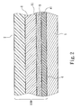
- FIG. 2 is a sectional view of the multi-layer structure bonded with the substrate.
- FIG. 3 is a sectional view of the multi-layer structure bonded with the substrate in a mold.
- the present invention aims to provide a multi-layer structure including a buffer layer.
- the multi-layer structure 100 at least includes a biological material layer 1 which at least has a first surface 11 to be bonded with a bonding layer 3 .
- the bonding layer 3 is bonded with a thermoplastic buffer layer 4 .
- the buffer layer 4 has a compressed surface to withstand high pressure and be bonded with a substrate 5 by thermal fusion (also referring to FIG. 2 ).
- the bonding layer 3 may be a thermo-melting adhesive to cover the biological material layer 1 in a thermal melting condition. With the buffer layer 4 compressed on the bonding layer 3 in the thermal melting condition, they have some portions mixed together on the junction between them.
- the buffer layer 4 can be selected from the group consisting of Polycarbonate (PC), Polymethyl Methacrylate (PMMA), modified PMMA, Acrylonitrile Butadiene Styrene (ABS), Polystyrene (PS), propylene-styrene copolymer, Polyvinylchloride (PVC), polyester, and combinations thereof.
- PC Polycarbonate
- PMMA Polymethyl Methacrylate
- ABS Acrylonitrile Butadiene Styrene
- PS Polystyrene
- PVC Polyvinylchloride
- the biological material 1 has a second surface on another side opposite to the first surface 11 , and an outer layer 2 attached to the second surface.
- the outer layer 2 aims to protect the surface of the biological material layer 1 without being damaged when being subjected to high temperature and pressure in a mold.
- the outer layer 2 can be a fixed film attached to the biological material layer 1 , and also can be colored through a dyeing process to provide aesthetic color and luster for the surface of the multi-layer structure 100 .
- the outer layer 2 may also be a release structure that can be peeled off.
- the outer layer 2 can be peeled off, and the second surface can be coated with paint in a spray coating process.
- the outer layer 2 may be a UV curable monomer or PU film.
- the outer layer 2 can be selected from the group consisting of Polyethylene terephthalate (PET), Polyethylene naphthalate (PEN), Polyethylene glycol-co-cyclohexane-1,4 dimethanol terephthalate (PETG), Thermalplastic polyurethane (TPU), Polyurethane (PU), Polypropylene (PP), Polycarbonate (PC), Amorphous polyethylene terephthalate (A-PET), Polyvinyl chloride (PVC), Acrylic, Methly-methacrylate-styrene (MS), Acrylonitrile-butadiene-styrene copolymer, Polystyrene (PS), Polyoxymethylene (POM), Nylon, and combinations thereof.
- PET Polyethylene terephthalate
- PEN Polyethylene glycol-co-cyclohexane-1,4 dimethanol terephthalate
- TPU Thermalplastic polyurethane
- PU Polyurethane
- PP Polypropylene
- PC Polycarbonate
- the multi-layer structure 100 is boned with a substrate 5 in a die.
- the die includes a male core 91 and a female cavity 92 .
- the multi-layer structure 100 is positioned on the female cavity 92 in advance, then the male core 91 and the female cavity 92 are coupled together to form a closed chamber to inject the substrate 5 onto the multi-layer structure 100 at high pressure and temperature.
- the injection temperature of the substrate 5 is ranged from 200° C. to 300° C.
- the pressure in the mold is ranged from 180 tons to 500 tons. Also referring to FIG.
- the thermoplastic buffer layer 4 is fused closely with the substrate 5 under the high temperature and pressure. Meanwhile, the buffer layer 4 withstands the pressure and temperature first when the substrate 5 is injected onto the multi-layer structure 100 ; then the pressure and temperature are distributed to other layers of the multi-layer structure 100 .
- the pressure withstood by the biological material layer 1 is much smaller than that of the conventional techniques, so that the biological material layer 1 is not damaged by the pressure and temperature in the die.
- the multi-layer structure 100 and substrate 5 can form a bonding between them with longer lifespan.
- the female cavity 92 may have at least one texture 93 formed thereon. Through the pressure of the die, the outer surface of the outer layer 2 can form a three-dimensional texture to further improve the profile appeal and touch feeling of the multi-layer structure 100 .
- the present invention provides a significant improvement over the conventional techniques and complies with the patent application requirements, and is submitted for review and granting of the commensurate patent rights.
Abstract
A multi-layer structure including a buffer layer is to couple with a substrate in a die. The multi-layer structure includes a biological material layer, a bonding layer and a thermoplastic buffer layer. The biological material layer has a first surface attached to the bonding layer. The buffer layer has one side boned with the bonding layer. The buffer layer has a compressed surface to withstand high pressure and be bonded to the substrate. The bonding layer and buffer layer are made of thermoplastic material, and are bonded together firmly through thermal fusion. The compressed surface of the buffer layer directly withstands the injection temperature and pressure exerting to the substrate in the mold, therefore can alleviate the temperature and pressure withstood by the biological material layer. Hence the biological material layer is protected without being damaged in the mold, and bonding between the multi-layer structure and substrate has longer lifespan.
Description
- The present invention relates to a multi-layer structure including a buffer layer and particularly to a multi-layer structure including a biological material layer to be coupled with a substrate in a mold and a buffer layer to alleviate high pressure and high temperature in the mold to avert damage of the biological material layer.
- Industrial products, in addition to providing desirable performance, also must improve appearance, touch feeling and identification of the product through innovative and aesthetic profile design to enhance product orientation and prices on the market. Many conventional industrial products, such as handsets or notebook computers, have plastic casings. Although some of them are coated with paint to provide shades different from plastics, they still have notable plastic touch feeling. After being used for a period of time or being subjected to abrasion, the paint on the surface is worn away and the plastic surface is exposed. Hence the plastic casing coated with paint generally does not have attractive appearance and desirable tough feeling.
- There are also products formed with metal material on the casings. The surface of the casing is simply treated such that metal textures and touch feeling become distinguishing features of the product. For instance, R.O.C. patent No. M346244 entitled “Surface coating structure for casings of electronic devices” discloses a sputtering layer formed on a substrate. The sputtering layer has an oxidation layer on the surface and treated by an anodizing treatment. The sputtering layer can be made of copper, brass, titanium alloy, aluminum or the like. However, the metal material provides limited diversity of color and touch feeling, and also is not elastic and renders cold feeling.
- To remedy the aforesaid shortcomings, technique of combining biological material (such as wood, leather or the like) with metal has been developed. For instance, R.O.C. patent No. M321677 entitled “Composite casing structure” discloses a casing consisting of a surface layer and a bottom layer. The surface layer can be formed with patterns through digital or transfer printing. The bottom layer is a metal sheet. A layer of adhesive is provided between the bottom side of the surface layer and the surface of the bottom layer to bond the surface layer and bottom layer together.
- However, the biological material boned on the metal surface through the adhesive tends to be peeled off from the edge thereof after a period of time or when being subjected to abrasion or impact. Air bubbles formed by defective bonding may also occur. Other factors such as abrasion also could cause dislocation of the biological material. In short, bonding the biological material through the adhesive with metal or plastics that differ very much in characteristics is prone to be loosened off after a period of time. Moreover, in the event that the biological material and the substrate are formed by pressing and punching, although they might be boned firmly at the beginning, since there is no buffer structure between them to alleviate the impact and high temperature during pressing and punching, the biological material is easily damaged. Moreover, the biological material and substrate have different static stress variations, they tend to be shrunk at different amount after a long duration and result in breaking and forming small cracks that cause peeling off or bulging out on the surface.
- In view of the biological material bonded with the substrate is easily damaged by injection temperature and pressure in the mold by adopting the conventional techniques and results in separation of the biological material and substrate, an object of the present invention aims to provide a multi-layer structure to prevent the biological material from being damaged by temperature and pressure in a mold, thereby to prolong the lifespan of the multi-layer structure and substrate that are boned together.
- The present invention provides a multi-layer structure including a buffer layer, and the multi-layer structure is boned with a substrate in a die. The multi-layer structure includes at least one biological material layer, a bonding layer and a thermoplastic buffer layer. The biological material layer at least has a first surface bonded to the bonding layer. The buffer layer has one side boned with the bonding layer. The buffer layer has a compressed surface to withstand high pressure and be bonded with the substrate by fusion. The bonding layer and buffer layer are made of thermoplastic material, and are bonded together firmly through thermal fusion. The compressed surface of the buffer layer directly withstands the injection temperature and pressure in the mold from the substrate, therefore can alleviate the temperature and pressure sustained by the biological material layer. Hence the biological material layer is protected without being damaged in the mold, and the bonding between the multi-layer structure and the substrate can have a longer lifespan.
- The foregoing, as well as additional objects, features and advantages of the invention will be more readily apparent from the following detailed description, which proceeds with reference to the accompanying drawings.
-
FIG. 1 is a sectional view of the multi-layer structure. -
FIG. 2 is a sectional view of the multi-layer structure bonded with the substrate. -
FIG. 3 is a sectional view of the multi-layer structure bonded with the substrate in a mold. - The present invention aims to provide a multi-layer structure including a buffer layer. Referring to
FIG. 1 , themulti-layer structure 100 at least includes a biological material layer 1 which at least has afirst surface 11 to be bonded with abonding layer 3. Thebonding layer 3 is bonded with athermoplastic buffer layer 4. Thebuffer layer 4 has a compressed surface to withstand high pressure and be bonded with asubstrate 5 by thermal fusion (also referring toFIG. 2 ). While thebuffer layer 4 is made of thermoplastic material, thebonding layer 3 may be a thermo-melting adhesive to cover the biological material layer 1 in a thermal melting condition. With thebuffer layer 4 compressed on thebonding layer 3 in the thermal melting condition, they have some portions mixed together on the junction between them. After cooling, afusion surface 41 is formed between thebuffer layer 4 andbonding layer 3. Thefusion surface 41 is formed by condensation of the mixture of thebonding layer 3 andbuffer layer 4. Hence a strong fusion structure is formed between thebuffer layer 4 andbonding layer 3. This can indirectly ensure that thebuffer layer 4 is positioned on one side of the biological material layer 1. Thebuffer layer 4 can be selected from the group consisting of Polycarbonate (PC), Polymethyl Methacrylate (PMMA), modified PMMA, Acrylonitrile Butadiene Styrene (ABS), Polystyrene (PS), propylene-styrene copolymer, Polyvinylchloride (PVC), polyester, and combinations thereof. It is to be noted that material selection for thebuffer layer 4 depends on thermal and pressurized fusion requirement for the bonding material to carry out the aforesaid technique. The biological material 1 has a second surface on another side opposite to thefirst surface 11, and anouter layer 2 attached to the second surface. Theouter layer 2 aims to protect the surface of the biological material layer 1 without being damaged when being subjected to high temperature and pressure in a mold. Theouter layer 2 can be a fixed film attached to the biological material layer 1, and also can be colored through a dyeing process to provide aesthetic color and luster for the surface of themulti-layer structure 100. In addition, theouter layer 2 may also be a release structure that can be peeled off. After the second surface protects the biological material layer 1 from being damaged by high temperature and pressure, theouter layer 2 can be peeled off, and the second surface can be coated with paint in a spray coating process. Theouter layer 2 may be a UV curable monomer or PU film. More specifically, theouter layer 2 can be selected from the group consisting of Polyethylene terephthalate (PET), Polyethylene naphthalate (PEN), Polyethylene glycol-co-cyclohexane-1,4 dimethanol terephthalate (PETG), Thermalplastic polyurethane (TPU), Polyurethane (PU), Polypropylene (PP), Polycarbonate (PC), Amorphous polyethylene terephthalate (A-PET), Polyvinyl chloride (PVC), Acrylic, Methly-methacrylate-styrene (MS), Acrylonitrile-butadiene-styrene copolymer, Polystyrene (PS), Polyoxymethylene (POM), Nylon, and combinations thereof. - Referring to
FIGS. 2 and 3 , themulti-layer structure 100 is boned with asubstrate 5 in a die. As shown inFIG. 3 , the die includes amale core 91 and afemale cavity 92. Themulti-layer structure 100 is positioned on thefemale cavity 92 in advance, then themale core 91 and thefemale cavity 92 are coupled together to form a closed chamber to inject thesubstrate 5 onto themulti-layer structure 100 at high pressure and temperature. The injection temperature of thesubstrate 5 is ranged from 200° C. to 300° C., and the pressure in the mold is ranged from 180 tons to 500 tons. Also referring toFIG. 2 , with thesubstrate 5 injected and formed on thebuffer layer 4, thethermoplastic buffer layer 4 is fused closely with thesubstrate 5 under the high temperature and pressure. Meanwhile, thebuffer layer 4 withstands the pressure and temperature first when thesubstrate 5 is injected onto themulti-layer structure 100; then the pressure and temperature are distributed to other layers of themulti-layer structure 100. Hence the pressure withstood by the biological material layer 1 is much smaller than that of the conventional techniques, so that the biological material layer 1 is not damaged by the pressure and temperature in the die. As a result, themulti-layer structure 100 andsubstrate 5 can form a bonding between them with longer lifespan. Moreover, thefemale cavity 92 may have at least onetexture 93 formed thereon. Through the pressure of the die, the outer surface of theouter layer 2 can form a three-dimensional texture to further improve the profile appeal and touch feeling of themulti-layer structure 100. - While the invention has been described by means of specific embodiment, numerous modifications and variations could be made thereto by those skilled in the art without departing from the scope and spirit of the invention set forth in the claims.
- In summation of the above description, the present invention provides a significant improvement over the conventional techniques and complies with the patent application requirements, and is submitted for review and granting of the commensurate patent rights.
Claims (12)
1. A multi-layer structure including a buffer layer to coupled with a substrate in a die, comprising:
a biological material layer including at least one first surface;
a bonding layer attached to the first surface; and
a thermoplastic buffer layer which is boned with the bonding layer and includes a compressed surface to withstand high pressure to be bonded with the substrate by fusion.
2. The multi-layer structure of claim 1 , wherein the biological material layer further includes a second surface on another side opposite to the first surface and an outer layer attached to the second surface.
3. The multi-layer structure of claim 2 , wherein the outer layer is colored through a dyeing process.
4. The multi-layer structure of claim 2 , wherein the outer layer is a UV curable monomer or a PU film.
5. The multi-layer structure of claim 2 , wherein the outer layer is selected from the group consisting of Polyethylene terephthalate (PET), Polyethylene naphthalate (PEN), Polyethylene glycol-co-cyclohexane-1,4 dimethanol terephthalate (PETG), Thermalplastic polyurethane (TPU), Polyurethane (PU), Polypropylene (PP), Polycarbonate (PC), Amorphous polyethylene terephthalate (A-PET), Polyvinyl chloride (PVC), Acrylic, Methly-methacrylate-styrene (MS), Acrylonetrile-butadiene-styrene copolymer, Polystyrene (PS), Polyoxymethylene (POM), Nylon, and combinations thereof.
6. The multi-layer structure of claim 1 , wherein the buffer layer is made of thermoplastic material and the bonding layer is a thermo-melting adhesive to cover the biological material layer in a thermal melting condition, the buffer layer being pressed and bonded to the bonding layer.
7. The multi-layer structure of claim 6 , wherein the buffer layer and the bonding layer are boned by a fusion surface which is formed by condensing a mixture of the bonding layer and the buffer layer.
8. The multi-layer structure of claim 6 , wherein the buffer layer is selected from the group consisting of Polycarbonate (PC), Polymethyl Methacrylate (PMMA), modified PMMA, Acrylonitrile Butadiene Styrene (ABS), Polystyrene (PS), propylene-styrene copolymer, Polyvinylchloride (PVC), polyester, and combinations thereof.
9. The multi-layer structure of claim 1 , wherein the die includes a male core and a female cavity, the multi-layer structure being positioned on the female cavity, the male core and the female cavity being coupled together to allow the substrate to be injected and formed on the buffer layer.
10. The multi-layer structure of claim 9 , wherein the female cavity includes at least one texture.
11. The multi-layer structure of claim 9 , wherein the substrate is injected and formed at a temperature ranged from 200° C. to 300° C.
12. The multi-layer structure of claim 9 , wherein the substrate is injected into the die at a pressure ranged from 180 tons to 500 tons.
Applications Claiming Priority (2)
| Application Number | Priority Date | Filing Date | Title |
|---|---|---|---|
| TW098135919 | 2009-10-23 | ||
| TW98135919A TW201114591A (en) | 2009-10-23 | 2009-10-23 | Multi-layered structure including buffer layer |
Publications (1)
| Publication Number | Publication Date |
|---|---|
| US20110097592A1 true US20110097592A1 (en) | 2011-04-28 |
Family
ID=43898694
Family Applications (1)
| Application Number | Title | Priority Date | Filing Date |
|---|---|---|---|
| US12/884,883 Abandoned US20110097592A1 (en) | 2009-10-23 | 2010-09-17 | Multi-layer structure including a buffer layer |
Country Status (3)
| Country | Link |
|---|---|
| US (1) | US20110097592A1 (en) |
| JP (1) | JP2011088434A (en) |
| TW (1) | TW201114591A (en) |
Cited By (6)
| Publication number | Priority date | Publication date | Assignee | Title |
|---|---|---|---|---|
| CN102505514A (en) * | 2011-09-23 | 2012-06-20 | 东莞市雄林新材料科技有限公司 | PVC (polyvinyl chloride) film or PVC artificial leather coated with TPU (thermoplastic polyurethane) film and production process thereof |
| CN102505516A (en) * | 2011-09-23 | 2012-06-20 | 东莞市雄林新材料科技有限公司 | PU (polyurethane) artificial leather coated with TPU (thermoplastic polyurethane) membrane and production process thereof |
| US20140004314A1 (en) * | 2012-06-14 | 2014-01-02 | Faurecia Interieur Industrie | Trim element and associated manufacturing method |
| US20150075733A1 (en) * | 2013-09-13 | 2015-03-19 | Faurecia Innenraum Systeme Gmbh | Roller shutter and storage compartment comprising said roller shutter |
| CN106393903A (en) * | 2016-08-31 | 2017-02-15 | 惠州市摩码菱丽光电材料有限公司 | Protective film and preparation method thereof |
| US10231544B2 (en) * | 2016-04-11 | 2019-03-19 | Creative Plastic Concepts, Llc | Shelf product |
Citations (2)
| Publication number | Priority date | Publication date | Assignee | Title |
|---|---|---|---|---|
| US3418188A (en) * | 1962-05-09 | 1968-12-24 | Dunlop Rubber Co | Method for producing patent leather |
| JP2006175639A (en) * | 2004-12-21 | 2006-07-06 | Sanwa Screen Meiban:Kk | Three-dimensional leather insert-molded product and its molding method |
Family Cites Families (8)
| Publication number | Priority date | Publication date | Assignee | Title |
|---|---|---|---|---|
| US6960392B2 (en) * | 2000-03-30 | 2005-11-01 | Arkema | Structure comprising a binder layer non-delaminable with respect to a metallized substrate and peelable with respect to a polypropylene substrate |
| FR2807057A1 (en) * | 2000-03-30 | 2001-10-05 | Atofina | Multilayer structure for use in production of food packaging, drink bottles and aerosol containers, comprises metal or metallized substrate layer coated with layer of non-removable polypropylene-based binder |
| JP2002347007A (en) * | 2001-05-24 | 2002-12-04 | Kojima Press Co Ltd | Wood decorative laminate and its manufacturing method |
| JP2002347177A (en) * | 2001-05-25 | 2002-12-04 | Kojima Press Co Ltd | Wooden decorative laminated sheet and its manufacturing method |
| JP2005001349A (en) * | 2003-06-16 | 2005-01-06 | Yoshitaka Kono | Woody molded article and its manufacturing method |
| JP4993165B2 (en) * | 2005-10-28 | 2012-08-08 | 株式会社フクダコーポレーション | Synthetic leather or leather insert molding method |
| JP2007130890A (en) * | 2005-11-10 | 2007-05-31 | Sharp Corp | Method of insert molding of cabinet of electronic equipment and electronic equipment having cabinet covered with leather cover |
| JP5553984B2 (en) * | 2008-10-14 | 2014-07-23 | 小島プレス工業株式会社 | Method for manufacturing wooden decorative board and wooden decorative board |
-
2009
- 2009-10-23 TW TW98135919A patent/TW201114591A/en not_active IP Right Cessation
-
2010
- 2010-09-16 JP JP2010207633A patent/JP2011088434A/en active Pending
- 2010-09-17 US US12/884,883 patent/US20110097592A1/en not_active Abandoned
Patent Citations (2)
| Publication number | Priority date | Publication date | Assignee | Title |
|---|---|---|---|---|
| US3418188A (en) * | 1962-05-09 | 1968-12-24 | Dunlop Rubber Co | Method for producing patent leather |
| JP2006175639A (en) * | 2004-12-21 | 2006-07-06 | Sanwa Screen Meiban:Kk | Three-dimensional leather insert-molded product and its molding method |
Non-Patent Citations (1)
| Title |
|---|
| Machine translation of 2006175639 (2012). * |
Cited By (7)
| Publication number | Priority date | Publication date | Assignee | Title |
|---|---|---|---|---|
| CN102505514A (en) * | 2011-09-23 | 2012-06-20 | 东莞市雄林新材料科技有限公司 | PVC (polyvinyl chloride) film or PVC artificial leather coated with TPU (thermoplastic polyurethane) film and production process thereof |
| CN102505516A (en) * | 2011-09-23 | 2012-06-20 | 东莞市雄林新材料科技有限公司 | PU (polyurethane) artificial leather coated with TPU (thermoplastic polyurethane) membrane and production process thereof |
| US20140004314A1 (en) * | 2012-06-14 | 2014-01-02 | Faurecia Interieur Industrie | Trim element and associated manufacturing method |
| US20150075733A1 (en) * | 2013-09-13 | 2015-03-19 | Faurecia Innenraum Systeme Gmbh | Roller shutter and storage compartment comprising said roller shutter |
| US10030441B2 (en) * | 2013-09-13 | 2018-07-24 | Faurecia Innenraum Systeme Gmbh | Roller shutter and storage compartment comprising said roller shutter |
| US10231544B2 (en) * | 2016-04-11 | 2019-03-19 | Creative Plastic Concepts, Llc | Shelf product |
| CN106393903A (en) * | 2016-08-31 | 2017-02-15 | 惠州市摩码菱丽光电材料有限公司 | Protective film and preparation method thereof |
Also Published As
| Publication number | Publication date |
|---|---|
| JP2011088434A (en) | 2011-05-06 |
| TW201114591A (en) | 2011-05-01 |
| TWI404630B (en) | 2013-08-11 |
Similar Documents
| Publication | Publication Date | Title |
|---|---|---|
| US20110097592A1 (en) | Multi-layer structure including a buffer layer | |
| KR101496536B1 (en) | Decorating sheet, decorated resin molded article and method for production thereof | |
| US10252499B2 (en) | Process for forming transfer film | |
| US7727447B2 (en) | Product having sealed free edges and method to produce the product | |
| EP1872969B1 (en) | Transfer film, and synthetic resin molded product having decoration formed by transfer film | |
| US20100289187A1 (en) | Film for insert injection molding and insert injection molding method using the same | |
| US20130288011A1 (en) | Multilayer decorative film structure | |
| JP2010241138A (en) | In-mold decorative molding method and molded article | |
| CN108621484B (en) | Silica gel object with three-dimensional colorful pattern surface layer and manufacturing method thereof | |
| US20100255267A1 (en) | Molding method providing three-dimensional patterns in-mold and articles molded by the method | |
| US8221868B2 (en) | Finished product structure formed by in-mold decoration process | |
| US20090148674A1 (en) | In mold film with a 2d/3d pattern | |
| TWM580039U (en) | Composite structure of lamination | |
| KR101332533B1 (en) | Insert injection molding mehtod using inmold decoration film | |
| US20120018086A1 (en) | Method for fabricating composite material for in-mold decoration | |
| US11840008B2 (en) | Light-transmitting decorated molding article and method of fabricating the same | |
| TW201016431A (en) | Plastic product and method for manufacturing the same | |
| JP2011031614A (en) | Compound material article and method for manufacturing the same | |
| US20130200548A1 (en) | Industrial product structure combined with organic material | |
| US20180003359A1 (en) | Three dimensional glass structure, decorated molding article and method for fabricating decorated molding article | |
| CN101456268A (en) | Leather decoration plate and forming method | |
| CN102029682B (en) | Housing, production method therefor and electronic device | |
| JP2004017508A (en) | Molded decorative sheet and injection molding simultaneous decoration method | |
| CN102218797A (en) | Shell of electronic device and manufacturing method of shell | |
| CN102029851A (en) | Anti-scrap transfer laminated film |
Legal Events
| Date | Code | Title | Description |
|---|---|---|---|
| AS | Assignment |
Owner name: SUNTENG NEW TECHNOLOGY CO., LTD., TAIWAN Free format text: ASSIGNMENT OF ASSIGNORS INTEREST;ASSIGNOR:WANG, CHING-TU;REEL/FRAME:025007/0820 Effective date: 20100811 |
|
| STCB | Information on status: application discontinuation |
Free format text: ABANDONED -- FAILURE TO RESPOND TO AN OFFICE ACTION |