US20110076216A1 - Carbon Dioxide Capture Power Generation System - Google Patents
Carbon Dioxide Capture Power Generation System Download PDFInfo
- Publication number
- US20110076216A1 US20110076216A1 US12/859,482 US85948210A US2011076216A1 US 20110076216 A1 US20110076216 A1 US 20110076216A1 US 85948210 A US85948210 A US 85948210A US 2011076216 A1 US2011076216 A1 US 2011076216A1
- Authority
- US
- United States
- Prior art keywords
- sulfuric acid
- carbon dioxide
- dioxide capture
- boiler
- power generation
- Prior art date
- Legal status (The legal status is an assumption and is not a legal conclusion. Google has not performed a legal analysis and makes no representation as to the accuracy of the status listed.)
- Granted
Links
- CURLTUGMZLYLDI-UHFFFAOYSA-N Carbon dioxide Chemical compound O=C=O CURLTUGMZLYLDI-UHFFFAOYSA-N 0.000 title claims abstract description 188
- 239000001569 carbon dioxide Substances 0.000 title claims abstract description 93
- 229910002092 carbon dioxide Inorganic materials 0.000 title claims abstract description 93
- 238000010248 power generation Methods 0.000 title claims abstract description 34
- QAOWNCQODCNURD-UHFFFAOYSA-N Sulfuric acid Chemical compound OS(O)(=O)=O QAOWNCQODCNURD-UHFFFAOYSA-N 0.000 claims abstract description 572
- 239000007789 gas Substances 0.000 claims abstract description 171
- 238000006477 desulfuration reaction Methods 0.000 claims abstract description 27
- 230000023556 desulfurization Effects 0.000 claims abstract description 27
- 239000000446 fuel Substances 0.000 claims abstract description 27
- QVGXLLKOCUKJST-UHFFFAOYSA-N atomic oxygen Chemical compound [O] QVGXLLKOCUKJST-UHFFFAOYSA-N 0.000 claims abstract description 20
- 229910052760 oxygen Inorganic materials 0.000 claims abstract description 20
- 239000001301 oxygen Substances 0.000 claims abstract description 20
- 229910052815 sulfur oxide Inorganic materials 0.000 claims abstract description 20
- 238000011144 upstream manufacturing Methods 0.000 claims abstract description 14
- XTQHKBHJIVJGKJ-UHFFFAOYSA-N sulfur monoxide Chemical class S=O XTQHKBHJIVJGKJ-UHFFFAOYSA-N 0.000 claims abstract description 10
- 239000003463 adsorbent Substances 0.000 claims description 96
- 239000003245 coal Substances 0.000 claims description 39
- QSHDDOUJBYECFT-UHFFFAOYSA-N mercury Chemical compound [Hg] QSHDDOUJBYECFT-UHFFFAOYSA-N 0.000 claims description 29
- 229910052753 mercury Inorganic materials 0.000 claims description 29
- 230000018044 dehydration Effects 0.000 claims description 23
- 238000006297 dehydration reaction Methods 0.000 claims description 23
- OKTJSMMVPCPJKN-UHFFFAOYSA-N Carbon Chemical compound [C] OKTJSMMVPCPJKN-UHFFFAOYSA-N 0.000 claims description 18
- 238000000034 method Methods 0.000 claims description 16
- 238000007599 discharging Methods 0.000 claims description 12
- 239000002028 Biomass Substances 0.000 claims description 9
- 239000000843 powder Substances 0.000 claims description 4
- 238000004064 recycling Methods 0.000 claims description 2
- 238000002485 combustion reaction Methods 0.000 abstract description 69
- 229920006395 saturated elastomer Polymers 0.000 description 17
- 239000003595 mist Substances 0.000 description 14
- 230000007797 corrosion Effects 0.000 description 13
- 238000005260 corrosion Methods 0.000 description 13
- 238000001179 sorption measurement Methods 0.000 description 13
- IJGRMHOSHXDMSA-UHFFFAOYSA-N Atomic nitrogen Chemical compound N#N IJGRMHOSHXDMSA-UHFFFAOYSA-N 0.000 description 11
- XLYOFNOQVPJJNP-UHFFFAOYSA-N water Substances O XLYOFNOQVPJJNP-UHFFFAOYSA-N 0.000 description 9
- 239000002250 absorbent Substances 0.000 description 7
- 230000002745 absorbent Effects 0.000 description 7
- 229910001861 calcium hydroxide Inorganic materials 0.000 description 7
- 238000001816 cooling Methods 0.000 description 7
- ODINCKMPIJJUCX-UHFFFAOYSA-N Calcium oxide Chemical compound [Ca]=O ODINCKMPIJJUCX-UHFFFAOYSA-N 0.000 description 6
- 239000000428 dust Substances 0.000 description 6
- 229910052757 nitrogen Inorganic materials 0.000 description 6
- RCTYPNKXASFOBE-UHFFFAOYSA-M chloromercury Chemical compound [Hg]Cl RCTYPNKXASFOBE-UHFFFAOYSA-M 0.000 description 5
- 230000007423 decrease Effects 0.000 description 5
- 230000006870 function Effects 0.000 description 5
- 229910052751 metal Inorganic materials 0.000 description 5
- 239000002184 metal Substances 0.000 description 5
- 239000002002 slurry Substances 0.000 description 5
- 239000012719 wet electrostatic precipitator Substances 0.000 description 5
- 239000010883 coal ash Substances 0.000 description 4
- 239000007788 liquid Substances 0.000 description 4
- 235000011149 sulphuric acid Nutrition 0.000 description 4
- 239000002699 waste material Substances 0.000 description 4
- 230000000274 adsorptive effect Effects 0.000 description 3
- 229910052602 gypsum Inorganic materials 0.000 description 3
- 239000010440 gypsum Substances 0.000 description 3
- MWUXSHHQAYIFBG-UHFFFAOYSA-N nitrogen oxide Inorganic materials O=[N] MWUXSHHQAYIFBG-UHFFFAOYSA-N 0.000 description 3
- 238000000926 separation method Methods 0.000 description 3
- QGZKDVFQNNGYKY-UHFFFAOYSA-N Ammonia Chemical compound N QGZKDVFQNNGYKY-UHFFFAOYSA-N 0.000 description 2
- 229910000990 Ni alloy Inorganic materials 0.000 description 2
- PXHVJJICTQNCMI-UHFFFAOYSA-N Nickel Chemical compound [Ni] PXHVJJICTQNCMI-UHFFFAOYSA-N 0.000 description 2
- 239000002253 acid Substances 0.000 description 2
- 230000003247 decreasing effect Effects 0.000 description 2
- 239000000463 material Substances 0.000 description 2
- 238000012545 processing Methods 0.000 description 2
- 238000010792 warming Methods 0.000 description 2
- 229910000497 Amalgam Inorganic materials 0.000 description 1
- 238000003916 acid precipitation Methods 0.000 description 1
- 230000002411 adverse Effects 0.000 description 1
- 238000005273 aeration Methods 0.000 description 1
- 229910021529 ammonia Inorganic materials 0.000 description 1
- AXCZMVOFGPJBDE-UHFFFAOYSA-L calcium dihydroxide Chemical compound [OH-].[OH-].[Ca+2] AXCZMVOFGPJBDE-UHFFFAOYSA-L 0.000 description 1
- 239000000920 calcium hydroxide Substances 0.000 description 1
- 235000011116 calcium hydroxide Nutrition 0.000 description 1
- 239000003054 catalyst Substances 0.000 description 1
- 230000008859 change Effects 0.000 description 1
- 239000000470 constituent Substances 0.000 description 1
- 230000007812 deficiency Effects 0.000 description 1
- 230000007613 environmental effect Effects 0.000 description 1
- 239000010419 fine particle Substances 0.000 description 1
- 238000003780 insertion Methods 0.000 description 1
- 230000037431 insertion Effects 0.000 description 1
- 238000004519 manufacturing process Methods 0.000 description 1
- VUZPPFZMUPKLLV-UHFFFAOYSA-N methane;hydrate Chemical compound C.O VUZPPFZMUPKLLV-UHFFFAOYSA-N 0.000 description 1
- 239000000203 mixture Substances 0.000 description 1
- 238000012544 monitoring process Methods 0.000 description 1
- 229910052759 nickel Inorganic materials 0.000 description 1
- 150000002829 nitrogen Chemical class 0.000 description 1
- 230000008569 process Effects 0.000 description 1
- 230000009467 reduction Effects 0.000 description 1
- 239000000779 smoke Substances 0.000 description 1
- 239000011343 solid material Substances 0.000 description 1
- 239000007921 spray Substances 0.000 description 1
- 238000005507 spraying Methods 0.000 description 1
- 230000000007 visual effect Effects 0.000 description 1
Images


Classifications
-
- F—MECHANICAL ENGINEERING; LIGHTING; HEATING; WEAPONS; BLASTING
- F23—COMBUSTION APPARATUS; COMBUSTION PROCESSES
- F23L—SUPPLYING AIR OR NON-COMBUSTIBLE LIQUIDS OR GASES TO COMBUSTION APPARATUS IN GENERAL ; VALVES OR DAMPERS SPECIALLY ADAPTED FOR CONTROLLING AIR SUPPLY OR DRAUGHT IN COMBUSTION APPARATUS; INDUCING DRAUGHT IN COMBUSTION APPARATUS; TOPS FOR CHIMNEYS OR VENTILATING SHAFTS; TERMINALS FOR FLUES
- F23L7/00—Supplying non-combustible liquids or gases, other than air, to the fire, e.g. oxygen, steam
- F23L7/007—Supplying oxygen or oxygen-enriched air
-
- B—PERFORMING OPERATIONS; TRANSPORTING
- B01—PHYSICAL OR CHEMICAL PROCESSES OR APPARATUS IN GENERAL
- B01D—SEPARATION
- B01D53/00—Separation of gases or vapours; Recovering vapours of volatile solvents from gases; Chemical or biological purification of waste gases, e.g. engine exhaust gases, smoke, fumes, flue gases, aerosols
- B01D53/34—Chemical or biological purification of waste gases
- B01D53/74—General processes for purification of waste gases; Apparatus or devices specially adapted therefor
- B01D53/75—Multi-step processes
-
- F—MECHANICAL ENGINEERING; LIGHTING; HEATING; WEAPONS; BLASTING
- F23—COMBUSTION APPARATUS; COMBUSTION PROCESSES
- F23C—METHODS OR APPARATUS FOR COMBUSTION USING FLUID FUEL OR SOLID FUEL SUSPENDED IN A CARRIER GAS OR AIR
- F23C9/00—Combustion apparatus characterised by arrangements for returning combustion products or flue gases to the combustion chamber
- F23C9/003—Combustion apparatus characterised by arrangements for returning combustion products or flue gases to the combustion chamber for pulverulent fuel
-
- F—MECHANICAL ENGINEERING; LIGHTING; HEATING; WEAPONS; BLASTING
- F23—COMBUSTION APPARATUS; COMBUSTION PROCESSES
- F23L—SUPPLYING AIR OR NON-COMBUSTIBLE LIQUIDS OR GASES TO COMBUSTION APPARATUS IN GENERAL ; VALVES OR DAMPERS SPECIALLY ADAPTED FOR CONTROLLING AIR SUPPLY OR DRAUGHT IN COMBUSTION APPARATUS; INDUCING DRAUGHT IN COMBUSTION APPARATUS; TOPS FOR CHIMNEYS OR VENTILATING SHAFTS; TERMINALS FOR FLUES
- F23L15/00—Heating of air supplied for combustion
- F23L15/04—Arrangements of recuperators
-
- B—PERFORMING OPERATIONS; TRANSPORTING
- B01—PHYSICAL OR CHEMICAL PROCESSES OR APPARATUS IN GENERAL
- B01D—SEPARATION
- B01D2253/00—Adsorbents used in seperation treatment of gases and vapours
- B01D2253/10—Inorganic adsorbents
- B01D2253/102—Carbon
-
- B—PERFORMING OPERATIONS; TRANSPORTING
- B01—PHYSICAL OR CHEMICAL PROCESSES OR APPARATUS IN GENERAL
- B01D—SEPARATION
- B01D2257/00—Components to be removed
- B01D2257/40—Nitrogen compounds
- B01D2257/404—Nitrogen oxides other than dinitrogen oxide
-
- B—PERFORMING OPERATIONS; TRANSPORTING
- B01—PHYSICAL OR CHEMICAL PROCESSES OR APPARATUS IN GENERAL
- B01D—SEPARATION
- B01D2257/00—Components to be removed
- B01D2257/50—Carbon oxides
- B01D2257/504—Carbon dioxide
-
- B—PERFORMING OPERATIONS; TRANSPORTING
- B01—PHYSICAL OR CHEMICAL PROCESSES OR APPARATUS IN GENERAL
- B01D—SEPARATION
- B01D2257/00—Components to be removed
- B01D2257/60—Heavy metals or heavy metal compounds
-
- B—PERFORMING OPERATIONS; TRANSPORTING
- B01—PHYSICAL OR CHEMICAL PROCESSES OR APPARATUS IN GENERAL
- B01D—SEPARATION
- B01D2258/00—Sources of waste gases
- B01D2258/02—Other waste gases
- B01D2258/0283—Flue gases
-
- B—PERFORMING OPERATIONS; TRANSPORTING
- B01—PHYSICAL OR CHEMICAL PROCESSES OR APPARATUS IN GENERAL
- B01D—SEPARATION
- B01D53/00—Separation of gases or vapours; Recovering vapours of volatile solvents from gases; Chemical or biological purification of waste gases, e.g. engine exhaust gases, smoke, fumes, flue gases, aerosols
- B01D53/34—Chemical or biological purification of waste gases
- B01D53/46—Removing components of defined structure
- B01D53/48—Sulfur compounds
- B01D53/50—Sulfur oxides
-
- B—PERFORMING OPERATIONS; TRANSPORTING
- B01—PHYSICAL OR CHEMICAL PROCESSES OR APPARATUS IN GENERAL
- B01D—SEPARATION
- B01D53/00—Separation of gases or vapours; Recovering vapours of volatile solvents from gases; Chemical or biological purification of waste gases, e.g. engine exhaust gases, smoke, fumes, flue gases, aerosols
- B01D53/34—Chemical or biological purification of waste gases
- B01D53/46—Removing components of defined structure
- B01D53/54—Nitrogen compounds
- B01D53/56—Nitrogen oxides
-
- B—PERFORMING OPERATIONS; TRANSPORTING
- B01—PHYSICAL OR CHEMICAL PROCESSES OR APPARATUS IN GENERAL
- B01D—SEPARATION
- B01D53/00—Separation of gases or vapours; Recovering vapours of volatile solvents from gases; Chemical or biological purification of waste gases, e.g. engine exhaust gases, smoke, fumes, flue gases, aerosols
- B01D53/34—Chemical or biological purification of waste gases
- B01D53/46—Removing components of defined structure
- B01D53/62—Carbon oxides
-
- B—PERFORMING OPERATIONS; TRANSPORTING
- B01—PHYSICAL OR CHEMICAL PROCESSES OR APPARATUS IN GENERAL
- B01D—SEPARATION
- B01D53/00—Separation of gases or vapours; Recovering vapours of volatile solvents from gases; Chemical or biological purification of waste gases, e.g. engine exhaust gases, smoke, fumes, flue gases, aerosols
- B01D53/34—Chemical or biological purification of waste gases
- B01D53/46—Removing components of defined structure
- B01D53/64—Heavy metals or compounds thereof, e.g. mercury
-
- F—MECHANICAL ENGINEERING; LIGHTING; HEATING; WEAPONS; BLASTING
- F23—COMBUSTION APPARATUS; COMBUSTION PROCESSES
- F23J—REMOVAL OR TREATMENT OF COMBUSTION PRODUCTS OR COMBUSTION RESIDUES; FLUES
- F23J2215/00—Preventing emissions
- F23J2215/20—Sulfur; Compounds thereof
-
- F—MECHANICAL ENGINEERING; LIGHTING; HEATING; WEAPONS; BLASTING
- F23—COMBUSTION APPARATUS; COMBUSTION PROCESSES
- F23J—REMOVAL OR TREATMENT OF COMBUSTION PRODUCTS OR COMBUSTION RESIDUES; FLUES
- F23J2215/00—Preventing emissions
- F23J2215/50—Carbon dioxide
-
- F—MECHANICAL ENGINEERING; LIGHTING; HEATING; WEAPONS; BLASTING
- F23—COMBUSTION APPARATUS; COMBUSTION PROCESSES
- F23J—REMOVAL OR TREATMENT OF COMBUSTION PRODUCTS OR COMBUSTION RESIDUES; FLUES
- F23J2219/00—Treatment devices
- F23J2219/30—Sorption devices using carbon, e.g. coke
-
- Y—GENERAL TAGGING OF NEW TECHNOLOGICAL DEVELOPMENTS; GENERAL TAGGING OF CROSS-SECTIONAL TECHNOLOGIES SPANNING OVER SEVERAL SECTIONS OF THE IPC; TECHNICAL SUBJECTS COVERED BY FORMER USPC CROSS-REFERENCE ART COLLECTIONS [XRACs] AND DIGESTS
- Y02—TECHNOLOGIES OR APPLICATIONS FOR MITIGATION OR ADAPTATION AGAINST CLIMATE CHANGE
- Y02A—TECHNOLOGIES FOR ADAPTATION TO CLIMATE CHANGE
- Y02A50/00—TECHNOLOGIES FOR ADAPTATION TO CLIMATE CHANGE in human health protection, e.g. against extreme weather
- Y02A50/20—Air quality improvement or preservation, e.g. vehicle emission control or emission reduction by using catalytic converters
-
- Y—GENERAL TAGGING OF NEW TECHNOLOGICAL DEVELOPMENTS; GENERAL TAGGING OF CROSS-SECTIONAL TECHNOLOGIES SPANNING OVER SEVERAL SECTIONS OF THE IPC; TECHNICAL SUBJECTS COVERED BY FORMER USPC CROSS-REFERENCE ART COLLECTIONS [XRACs] AND DIGESTS
- Y02—TECHNOLOGIES OR APPLICATIONS FOR MITIGATION OR ADAPTATION AGAINST CLIMATE CHANGE
- Y02C—CAPTURE, STORAGE, SEQUESTRATION OR DISPOSAL OF GREENHOUSE GASES [GHG]
- Y02C20/00—Capture or disposal of greenhouse gases
- Y02C20/40—Capture or disposal of greenhouse gases of CO2
-
- Y—GENERAL TAGGING OF NEW TECHNOLOGICAL DEVELOPMENTS; GENERAL TAGGING OF CROSS-SECTIONAL TECHNOLOGIES SPANNING OVER SEVERAL SECTIONS OF THE IPC; TECHNICAL SUBJECTS COVERED BY FORMER USPC CROSS-REFERENCE ART COLLECTIONS [XRACs] AND DIGESTS
- Y02—TECHNOLOGIES OR APPLICATIONS FOR MITIGATION OR ADAPTATION AGAINST CLIMATE CHANGE
- Y02E—REDUCTION OF GREENHOUSE GAS [GHG] EMISSIONS, RELATED TO ENERGY GENERATION, TRANSMISSION OR DISTRIBUTION
- Y02E20/00—Combustion technologies with mitigation potential
- Y02E20/32—Direct CO2 mitigation
-
- Y—GENERAL TAGGING OF NEW TECHNOLOGICAL DEVELOPMENTS; GENERAL TAGGING OF CROSS-SECTIONAL TECHNOLOGIES SPANNING OVER SEVERAL SECTIONS OF THE IPC; TECHNICAL SUBJECTS COVERED BY FORMER USPC CROSS-REFERENCE ART COLLECTIONS [XRACs] AND DIGESTS
- Y02—TECHNOLOGIES OR APPLICATIONS FOR MITIGATION OR ADAPTATION AGAINST CLIMATE CHANGE
- Y02E—REDUCTION OF GREENHOUSE GAS [GHG] EMISSIONS, RELATED TO ENERGY GENERATION, TRANSMISSION OR DISTRIBUTION
- Y02E20/00—Combustion technologies with mitigation potential
- Y02E20/34—Indirect CO2mitigation, i.e. by acting on non CO2directly related matters of the process, e.g. pre-heating or heat recovery
Definitions
- the present invention relates to removal of sulfuric acid in a combustion exhaust gas which is required in a carbon dioxide capture power generation system.
- Coal thermal power stations are dominant emission sources of carbon dioxide, and high-efficiency separation and capture of the carbon dioxide in the combustion exhaust gas have become a subject to be challenged.
- JP-3068888 for example describes a method in which coal is combusted with oxygen. By combusting with oxygen which contains no nitrogen, the concentration of the carbon dioxide in the combustion exhaust gas can be increased so as to allow the high-efficient separation and capture of carbon dioxide.
- NOx nitrogen oxides
- SOx sulfur oxides
- equipments to purify these oxides are installed in the wake flow of the boiler.
- the NOx is converted to nitrogen by being reacted with ammonia using a denitration catalyst.
- the SOx is reacted with caustic lime to form gypsum.
- a part of the SOx becomes a sulfuric acid gas.
- the temperature of the combustion exhaust gas becomes the sulfuric acid dew point or lower, the acid liquefies and generates sulfuric acid mist.
- This sulfuric acid mist adheres to members of the equipment and pipings to cause corrosion of the members. Further, the sulfuric acid mist generates white smoke when discharged through a stack, causing visual pollution.
- the sulfuric acid mist becomes a source of acid rain. Due to these reasons, an equipment to remove sulfuric acid in the combustion exhaust gas is installed.
- Method to remove sulfuric acid mist includes, for example, a method of JP-A-2002-45643 is described, in which a wet electrostatic precipitator is provided in the wake flow of a desulfurization equipment to make the sulfuric acid mist charged to remove it and the sulfuric acid mist is coarsened to improve the removal performance.
- the carbon dioxide in the combustion exhaust gas is separated from non-condensable gases and captured by compressing and cooling the combustion exhaust gas to liquefy the carbon dioxide.
- the cooling temperature becomes about ⁇ 80° C. or lower.
- the sulfuric acid removal method in JP-A-2002-45643 is that the sulfuric acid obtained by liquefying the sulfuric acid gas to mist at the sulfuric acid dew point or lower is removed.
- a sulfuric acid gas corresponding to its saturated vapor pressure remains in the combustion exhaust gas. Since the saturated vapor pressure of the sulfuric acid gas decreases with temperature, the sulfuric acid gas liquefies as the gas is cooled down.
- the sulfuric acid gas liquefies during cooling, adheres to the members of the equipment, and causes the corrosion of the members. This acts as a hindrance to continuous running of the carbon dioxide capture equipment.
- An object of the present invention is to provide such method.
- the present invention employed a carbon dioxide capture power generation system provided with a boiler in which fuel is combusted in the oxygen atmosphere, a carbon dioxide capture equipment to remove the carbon dioxide in the wake flow of the boiler, a piping branching from the wake flow of the boiler to recycle the combustion exhaust gas to the boiler, a desulfurization equipment to remove sulfur oxides, and a sulfuric acid removal equipment to remove the sulfuric acid in the upstream of the carbon dioxide capture equipment and in the wake flow of the boiler.
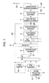
- FIG. 1 is a drawing illustrating a carbon dioxide capture power generation system provided with a sulfuric acid removal equipment according to the present embodiment.
- FIG. 2 is a graph representing the saturated vapor pressure curve of sulfuric acid according to the present embodiment.
- FIG. 3 is a drawing illustrating a carbon dioxide capture power generation system using a sulfuric acid adsorbent as a fuel according to the present embodiment.
- FIG. 4 is a drawing illustrating a carbon dioxide capture power generation system provided with a sulfuric acid removal equipment and a mercury removal equipment according to the present embodiment.
- FIG. 5 is a drawing illustrating a sulfuric acid adsorbent replacing system according to the present embodiment.
- FIG. 6 is a drawing illustrating a method of the sulfuric acid adsorbent replacing system according to the present embodiment.
- the present embodiment employed a carbon dioxide capture power generation system provided with a boiler in which fuel is combusted in the oxygen atmosphere, a carbon dioxide capture equipment which removes the carbon dioxide in the wake flow of the boiler, a piping branching from the wake flow of the boiler to recycle the combustion exhaust gas to the boiler, a desulfurization equipment to remove sulfur oxides and a sulfuric acid removal equipment to remove the sulfuric acid in the upstream of the carbon dioxide capture equipment and in the wake flow of the boiler.
- the desulfurization equipment to remove sulfur oxides in the wake flow of the boiler a dehydration equipment in the wake flow of the desulfurization equipment, the carbon dioxide capture equipment to remove the carbon dioxide in the wake flow of the dehydration equipment, and a piping branching from the wake flow of the boiler and being connected to the boiler to recycle the combustion exhaust gas
- the sulfuric acid removal equipment to remove the sulfuric acid gas was provided in the wake flow of the branch point to recycle the combustion exhaust gas to the boiler.
- the sulfuric acid removal equipment was provided in the upstream of the dehydration equipment.
- the sulfuric acid removal equipment employed a method to remove the sulfuric acid in a gas state by inserting a sulfuric acid adsorbent in the equipment.
- the sulfuric acid adsorbent was used in a powder form or in a blocky form.
- activated carbon biomass fuel or coal was used as the sulfuric acid adsorbent.
- Mercury is contained in the combustion exhaust gas.
- a mercury gas also liquefies by lowering temperature in the same manner as the sulfuric acid gas does, and adheres to the members of the equipment causing the corrosion of the members.
- the activated carbon, biomass fuel, or coal of the sulfuric acid adsorbent can also adsorb the mercury gas contained in the combustion exhaust gas.
- a mercury adsorption equipment was separately provided in the wake flow of the sulfuric acid removal equipment.
- the present invention employed the carbon dioxide capture power generation system provided with a boiler to combust a fuel in the oxygen atmosphere, a desulfurization equipment to remove sulfur oxides in the wake flow of the boiler, a dehydration equipment to remove moisture in the wake flow of the desulfurization equipment, a carbon dioxide capture equipment to remove the carbon dioxide in the wake flow of the dehydration equipment, a piping branching from the wake flow of the boiler to recycle the combustion exhaust gas to the boiler, and the sulfuric acid removal equipment to remove the sulfuric acid gas in the upstream of said dehydration equipment.
- the sulfuric acid gas liquefies at the sulfuric acid dew point or lower, adheres to members of the equipment resulting in the corrosion of the members.
- the sulfuric acid gas has been liquefied and atomized at the sulfuric acid dew point or lower, then removed, for example, using a wet electrostatic precipitator.
- a portion of the sulfuric acid gas corresponding to the saturated vapor pressure of sulfuric acid gas at a temperature at which the wet electrostatic precipitator is used, remains as sulfuric acid gas.
- An object of the present invention is to provide a method to prevent it.
- FIG. 1 Taking a coal thermal power generation system using pulverized coal as a fuel as an example, the carbon dioxide capture power generation system according to the present invention is represented in FIG. 1 .
- a denitrification equipment 2 to reduce the NOx to nitrogen an air heater 3 and a gas heater 4 to recover the heat of the combustion exhaust gas
- exhaust gas treatment equipments of a dust removal equipment 5 to remove coal ash and a desulfurization equipment 6 to remove the SOx exhaust gas treatment equipments of a dust removal equipment 5 to remove coal ash and a desulfurization equipment 6 to remove the SOx
- a sulfuric acid removal equipment 7 to remove the sulfuric acid
- a carbon dioxide capture equipment 9 to capture carbon dioxide are provided.
- An oxygen production equipment 12 takes in air 26 , produces oxygen 27 , and supplies the oxygen 27 to the boiler 1 .
- Coal transferred from a coal hopper 10 storing the coal is pulverized by a coal crasher 11 , supplied to the boiler 1 as pulverized coal, and combusted with oxygen.
- main components of the combustion exhaust gas become the carbon dioxide and water, and the concentration of the carbon dioxide can be made as high as 90% or more by removing the water.
- coal is combusted with air, since nitrogen amounting to about 80% of the air is not involved in combustion, it remains in the combustion exhaust gas as it is, and the concentration of the carbon dioxide generated by the combustion becomes as low as around 10%. Therefore, by combusting with oxygen, the concentration of the carbon dioxide can be increased, and the carbon dioxide can be efficiently captured.
- the combustion exhaust gas is aerated into the dehydration equipment 8 , cooled down to remove water 23 , then compressed and cooled down in the carbon dioxide capture equipment 9 , and separated to carbon dioxide 24 and non-condensable gases 25 to capture the carbon dioxide 24 .
- a circulating gas 22 is turned back to the boiler from a branch point 28 in the wake flow of desulfurization equipment 6 .
- a wet desulfurization system is employed in which slurry of caustic lime is formed and the slurry is sprayed.
- the SOx in the combustion exhaust gas is absorbed and removed by forming gypsum.
- the wet desulfurization has advantages that the removal rate for the SOx can be made as high as 98% or more, and further that the gypsum formed can be utilized effectively.
- the temperature of the combustion exhaust gas is lowered.
- the circulating gas 22 since it is passed through the desulfurization equipment 6 and its temperature is about 50° C., is heated up by the air heater 3 and supplied to the boiler 1 . By doing so, the heat efficiency of the boiler can be improved.
- a part of the SOx in the combustion exhaust gas is oxidized to the sulfuric acid gas.
- the combustion exhaust gas when cooled down to the sulfuric acid dew point or lower, liquefies to sulfuric acid mist. This sulfuric acid mist adheres to the members of equipment and causes the corrosion of the members.
- FIG. 2 a saturated vapor pressure curve of the sulfuric acid gas of the present embodiment is represented.
- the sulfuric acid gas is a hydrate of 100% sulfuric acid, and a saturated vapor pressure curve of 90% sulfuric acid and 10% water is represented as an example of the sulfuric acid mist composition.
- the sulfuric acid dew point at which the sulfuric acid gas liquefies varies depending on the sulfuric acid gas concentration and the water concentration, it is assumed here to be 130° C. at I in FIG. 2 .
- the sulfuric acid liquefies.
- a sulfuric acid gas corresponding to the saturated vapor pressure of A in FIG. 2 remains in the combustion exhaust gas.
- the temperature of the combustion exhaust gas is lowered to 50° C. at II in FIG. 2 , and the saturated vapor pressure is lowered to B in FIG. 2 .
- the sulfuric acid corresponding to the vapor pressure difference A ⁇ B liquefies.
- the cooling temperature in the dehydration equipment 8 is 20° C. at III in FIG. 2
- the sulfuric acid corresponding to the vapor pressure difference B ⁇ C liquefies
- the cooling temperature in the carbon dioxide capture equipment 9 is ⁇ 80° C.
- the sulfuric acid corresponding to the vapor pressure difference C ⁇ D liquefies.
- the insertion of the sulfuric acid adsorbent to adsorb the sulfuric acid gas will be explained using the saturated vapor pressure curve of sulfuric acid gas in FIG. 2 . If the cooling temperature in the carbon dioxide capture equipment 9 is ⁇ 80° C., the sulfuric acid corresponding to the vapor pressure difference C ⁇ D liquefies. However, by providing the sulfuric acid removal equipment 7 in the downstream side of the dehydration equipment 8 , the sulfuric acid corresponding to the vapor pressure difference C ⁇ D or more is removed in advance. By this, the carbon dioxide can be captured without the liquefaction of the sulfuric acid gas in the carbon dioxide capture equipment 9 , and with preventing the corrosion of the members.
- the sulfuric acid removal equipment 7 in the downstream side of the desulfurization equipment 6 , the sulfuric acid gas corresponding to the vapor pressure difference B ⁇ D or more is removed in advance.
- carbon dioxide can be captured without the liquefaction of the sulfuric acid gas in the dehydration equipment 8 and the carbon dioxide capture equipment 9 , and with preventing the corrosion of the members.
- the sulfuric acid gas remains at the saturated vapor pressure at A in FIG.
- the sulfuric acid gas corresponding to the vapor pressure difference A ⁇ B of the saturated vapor pressure is removed by the desulfurization equipment 6
- the sulfuric acid gas corresponding to the vapor pressure difference B ⁇ D or C ⁇ D or more in a state of sulfuric acid gas under the saturated vapor pressure curve is removed in the upstream of the carbon dioxide capture equipment 9 .
- the sulfuric acid removal equipment 7 is provided by calculating the amount of sulfuric acid gas to be removed based on the temperature and pressure obtained from this saturated vapor pressure curve of the sulfuric acid gas according to the equation of state of gas, then calculating the amount of sulfuric acid adsorbent to be required from the amount of sulfuric acid gas to be removed and the removal capability of the adsorbent.
- the sulfuric acid removal equipment 7 is desirably provided in the wake flow of the branch point 28 , and thereby the sulfuric acid removal equipment 7 can be downsized.
- branch point 28 is provided between the desulfurization equipment 6 and the sulfuric acid removal equipment 7 in FIG. 1
- the branch point may be provided between the dust removal equipment 5 and the desulfurization equipment 6 , or may be provided between the gas heater 4 and the dust removal equipment 5 .
- the sulfuric acid removal equipment 7 is desirably provided in the upstream of the dehydration equipment 8 . Even the combustion exhaust gas is cooled down in the dehydration equipment 8 , it can be avoided that the sulfuric acid gas liquefies in the dehydration equipment 8 by removing the sulfuric acid gas in the sulfuric acid removal equipment 7 so that the vapor pressure of the sulfuric acid gas becomes equal to or below the saturated vapor pressure at that temperature.
- the sulfuric acid adsorbent to adsorb the sulfuric acid gas is a solid material such as caustic lime, hydrated lime or activated carbon, and it is the form of powder or block. Since the sulfuric acid adsorbent is used in a dry state, the absorbent can adsorb not only the sulfuric acid gas but the sulfuric acid mist which is formed by the liquefaction of the sulfuric acid gas.
- the sulfuric acid removal equipment 7 is desirably a circulating fluidized bed equipment having functions of the capture and the recharge of the sulfuric acid adsorbent.
- the sulfuric acid removal equipment becomes a packed bed equipment.
- the sulfuric acid adsorbent does not flow out in the wake flow by being entrained with the combustion exhaust gas, it is necessary to secure a certain height of packed bed to gain contact area with the combustion exhaust gas.
- the adsorption ability is decreased earlier and further the absorbent earlier reaches a state of adsorption equilibrium in the upper stream of the packed bed, it becomes necessary to take out the sulfuric acid adsorbent in the upper stream and charge the absorbent to make up for the deficiency from the lower stream.
- the carbon dioxide capture power generation system provided with the boiler in which fuel is combusted in the oxygen atmosphere
- the carbon dioxide capture equipment to remove the carbon dioxide in the wake flow of the boiler
- the piping branching from the wake flow of the boiler to recycle the combustion exhaust gas to the boiler
- the desulfurization equipment to remove the sulfur oxides and the sulfuric acid removal equipment to remove the sulfuric acid gas in the upstream of the carbon dioxide capture equipment and in the wake flow of the boiler
- the sulfuric acid gas in the combustion exhaust gas can be removed up to the concentration under which the sulfuric acid gas does not liquefy at the temperature at which the carbon dioxide capture equipment is used in the upstream of the carbon dioxide capture equipment.
- the corrosion of the members can be prevented while the liquefaction of the sulfuric acid gas in the carbon dioxide capture equipment is avoided, as well as the sulfuric acid removal equipment can be downsized.
- the carbon dioxide capture power generation system having the dehydration equipment to remove moisture in the wake flow of the desulfurization equipment and provided with the sulfuric acid removal equipment in the upstream of the dehydration equipment, the liquefaction of the sulfuric acid gas in the dehydration equipment can be avoided.
- the used sulfuric acid adsorbent becomes a waste
- the adsorbent is of same carbonaceous one such as coal, like activated carbon
- the adsorbent can be used as a fuel instead of becoming a waste.
- the sulfuric acid adsorbed by the sulfuric acid adsorbent is emitted in the combustion exhaust gas as the SOx instead of the sulfuric acid gas by high-temperature combustion at 1,000° C. or higher, it does not result in an increase of the concentration of the sulfuric acid gas.
- the concentration of the sulfuric acid gas in the combustion exhaust gas is as low as several % of the SOx concentration, an extreme increase of the SOx concentration is not avoided.
- the sulfuric acid adsorbent is desirably the carbonaceous one, and coal, which is a fuel, can be used in the coal thermal power generation system. Further, since mixed combustion of coal and biomass has been implemented in the coal thermal power generation, the biomass fuel can be also used as the sulfuric acid adsorbent.
- a circulation fluidized bed equipment may be used for the sulfuric acid removal equipment, and when the absorbent is block coal, the packed bed equipment may be used for the sulfuric acid removal equipment.
- FIG. 3 a carbon dioxide capture power generation system using the sulfuric acid adsorbent according to the present invention as a fuel is represented.
- a sulfuric acid adsorbent hopper 31 is connected to the sulfuric acid removal equipment 7 so that the sulfuric acid adsorbent can be charged when needed.
- the block coal of the absorbent is transported to the coal hopper 10 in which the block coal is stored through a sulfuric acid adsorbent transporting pipe 32 , converted to pulverized coal by a coal crusher 11 , and then used as a fuel.
- the sulfuric acid adsorbent is the pulverized coal
- the absorbent may be made to join a pulverized coal transporting pipe 33 together, and supplied to the boiler 1 .
- the sulfuric acid adsorbent after adsorbing the sulfuric acid can be used as a fuel for the boiler, and the used sulfuric acid adsorbent can be effectively utilized avoiding the sulfuric acid adsorbent becoming a waste.
- the combustion exhaust gas of coal contains mercury gas.
- the mercury gas also liquefies by a decrease in temperature in the same way as sulfuric the acid gas does, and adheres to the members of equipments to cause the corrosion of the members.
- the activated carbon, coal or biomass fuel of the sulfuric acid adsorbent can also adsorb the mercury gas in the combustion exhaust gas, the absorbent can prevent liquefaction of the mercury in the equipment in the wake flow of the sulfuric acid removal equipment, for example, in the carbon dioxide capture equipment which is cooled down to ⁇ 80° C. or lower to protect the equipment members.
- the sulfuric acid adsorbent containing adsorbed sulfuric acid deteriorates in the adsorption ability for the mercury gas.
- the sulfuric acid adsorbent adsorbs the sulfuric acid mist in a liquid state
- the adsorption ability for the mercury gas deteriorates extremely, because the surface of the sulfuric acid adsorbent is covered with liquid. Therefore, an equipment is required to remove the mercury gas which cannot be removed in the sulfuric acid removal equipment.
- FIG. 4 the carbon dioxide capture power generation system provided with the sulfuric acid removal equipment and a mercury removal equipment according to the present embodiment is represented.
- a mercury removal equipment 13 was provided in the wake flow of the sulfuric acid removal equipment 7 .
- the mercury removal equipment 13 is located in the wake flow of the branch point 28 from where the combustion exhaust gas is circulated to reduce the gas volume in the same manner as in the sulfuric acid removal equipment, and thereby can be downsized.
- a metal mercury gas and a mercury chloride gas exist in the mercury gas in the combustion exhaust gas.
- the mercury chloride gas has an adsorptive property to coal ash and is further soluble in water.
- the mercury chloride adsorbed on the coal ash is removed by the dust removal equipment 5
- the mercury chloride in the combustion exhaust gas is also removed by the desulfurization equipment 6 .
- the mercury chloride is also removed by activated carbon, coal or biomass fuel of the sulfuric acid adsorbent which is charged into the sulfuric acid removal equipment 7 .
- the metal mercury gas has no adsorptive property to the coal ash nor solubility into the water, therefore, passes by the dust removal equipment 5 and the desulfurization equipment 6 .
- adsorption to the sulfuric acid adsorbent, activated carbon, coal and biomass fuel in the sulfuric acid removal equipment 7 is less.
- the mercury gas which cannot be removed by the sulfuric acid removal equipment is the metal mercury gas. Therefore, the mercury removal equipment 13 is desirably an equipment which is capable of removing the metal mercury gas.
- the material adsorbing the metal mercury gas includes nickel alloys, for example, SUS. The mercury gas reacts with nickel to form amalgam. It is desirable to charge the nickel alloy as an adsorbent into the mercury removal equipment.
- the mercury gas which cannot be removed by the sulfuric acid removal equipment can be removed by providing the mercury removal equipment in the wake flow of the sulfuric acid removal equipment.
- the sulfuric acid adsorbent reaches an adsorption equilibrium or an adsorption saturation after continuing to adsorb the sulfuric acid gas, and lose the adsorptive property. Accordingly, it becomes necessary arbitrarily to replenish the unused sulfuric acid adsorbent as well as to take out the adsorbed sulfuric acid adsorbent.
- FIG. 5 a replacing system for the sulfuric acid adsorbent according to the present invention is represented.
- the sulfuric acid removal equipment employs a method in which the combustion exhaust gas flows upward from the bottom side of the packed bed, assuming a packed bed equipment packed with block coal.
- the unused sulfuric acid adsorbent is charged through a sulfuric acid adsorbent charging valve 41 located midway of a piping connected to the sulfuric acid adsorbent hopper 31 and the sulfuric acid removal equipment 7 , and the sulfuric acid adsorbent containing adsorbed sulfuric acid is discharged from a sulfuric acid adsorbent discharging valve 42 located midway of the sulfuric acid adsorbent transporting piping 32 connected to the sulfuric acid removal equipment 7 .
- a sulfuric acid concentration measuring instrument 44 is provided at the exit of the sulfuric acid removal equipment so that the sulfuric acid concentration in the combustion exhaust gas can be measured.
- a sulfuric acid adsorbent control unit 43 has functions to take in a measured sulfuric acid concentration, compare the measured concentration with an upper limit concentration, and send out a signal to carry out opening/closing operation of the sulfuric acid adsorbent charging valve 41 and the sulfuric acid adsorbent discharging valve 42 when the measured concentration exceeds the upper limit concentration.
- the upper limit value of the sulfuric acid concentration is the concentration at which the sulfuric acid gas does not liquefy in the carbon dioxide capture equipment to be used at the lowest temperature.
- the upper limit concentration may be set by multiplying a safety rate, based on the saturated vapor pressure of sulfuric acid gas at the temperature at which the carbon dioxide capture equipment is used.
- FIG. 6 a replacement control method for the sulfuric acid adsorbent according to the present invention is represented.
- STEP I a sulfuric acid concentration C H2HO4 measured by the sulfuric acid concentration measuring instrument is input, and compared with the upper limit value of the sulfuric acid concentration C* H2SO4 .
- C H2HO4 ⁇ C* H2SO4 the monitoring of the sulfuric acid concentration is continued, because the sulfuric acid gas does not liquefy in the carbon dioxide capture equipment.
- the stage proceeds to STEP II, because the sulfuric acid gas liquefies in the carbon dioxide capture equipment.
- the sulfuric acid adsorbent charging valve B in is set OPEN, and the unused sulfuric acid adsorbent is charged.
- the stage proceeds to STEP III, the sulfuric acid adsorbent discharging valve B out is set OPEN, and the sulfuric acid adsorbent containing the adsorbed sulfuric acid is discharged.
- + ⁇ W is an input per one time for the sulfuric acid adsorbent. If this value is set large, the sulfuric acid adsorbent of an amount exceeding the capacity of the sulfuric acid removal equipment might be charged in STEP II. Since this might adversely affect on the aeration of the combustion exhaust gas, the + ⁇ W is desirably set at a value compatible to the capacity of the equipment. On the other hand, ⁇ W is a discharging amount per one time for the sulfuric acid adsorbent. By making ⁇ W for charge and discharge equivalent, the amount of the sulfuric acid adsorbent in the equipment can be maintained constant.
- the ⁇ W for charging and discharging are made equal by using the same rotary valves for the sulfuric acid adsorbent charging valve and the sulfuric acid adsorbent discharging valve, and making the conditions of the numbers of revolutions and operation times thereof the same.
- the ⁇ W for charging and discharging are made equal by providing a load cell in the sulfuric acid adsorbent hopper and the sulfuric acid removal equipment, and measuring a weight change.
- the adsorption ability of the sulfuric acid adsorbent can be appropriately controlled, by providing the control unit equipped with the sulfuric acid concentration measuring instrument at the exit of the combustion exhaust gas in the sulfuric acid removal equipment, reading the measured value, and opening the sulfuric acid charging valve to charge the unused sulfuric acid adsorbent, as well as opening the sulfuric acid discharging valve to discharge the sulfuric acid adsorbent containing adsorbed sulfuric acid in the sulfuric acid removal equipment, when the sulfuric acid concentration is equal to or over the prescribed value.
- STEP II and STEP III may be inversely sequenced depending on the situation.
- the control unit mentioned above can be implemented by using a computer etc. equipped with a memory and CPU.
- processings of STEPs I to III as being functions provided by the units are program modules, each function can be implemented by reading the modules and making the computer to execute. Data are stored in the memory device, which can be read in the processing.
- each function of the control unit can be implemented.
Landscapes
- Engineering & Computer Science (AREA)
- Chemical & Material Sciences (AREA)
- Combustion & Propulsion (AREA)
- Mechanical Engineering (AREA)
- General Engineering & Computer Science (AREA)
- Environmental & Geological Engineering (AREA)
- Health & Medical Sciences (AREA)
- Biomedical Technology (AREA)
- Analytical Chemistry (AREA)
- General Chemical & Material Sciences (AREA)
- Oil, Petroleum & Natural Gas (AREA)
- Chemical Kinetics & Catalysis (AREA)
- Treating Waste Gases (AREA)
- Solid-Sorbent Or Filter-Aiding Compositions (AREA)
Abstract
Description
- The present invention relates to removal of sulfuric acid in a combustion exhaust gas which is required in a carbon dioxide capture power generation system.
- Recently, global warming is attracting attention as a global environmental issue. It has become clear that the increase of carbon dioxide concentration in the atmosphere is the main factor of the global warming, and reduction of carbon dioxide emission has become important.
- Coal thermal power stations are dominant emission sources of carbon dioxide, and high-efficiency separation and capture of the carbon dioxide in the combustion exhaust gas have become a subject to be challenged.
- In the conventional coal thermal power generation, fuel is combusted using air, and the air contains an about 80% of nitrogen which is not involved in the combustion, and this nitrogen has been a disincentive for the high-efficiency separation and capture of carbon dioxide.
- In order to remove this disincentive, JP-3068888, for example describes a method in which coal is combusted with oxygen. By combusting with oxygen which contains no nitrogen, the concentration of the carbon dioxide in the combustion exhaust gas can be increased so as to allow the high-efficient separation and capture of carbon dioxide.
- On the other hand, since the temperature of the combustion exhaust gas becomes high in the combustion with oxygen, in order to prevent boiler materials from becoming intolerable against the temperature, a part of the combustion exhaust gas is recycled to the boiler to decrease oxygen concentration, and thereby the temperature of the combustion exhaust gas is maintained at a level similar to the case of the combustion with air.
- Since when coal is combusted in a boiler, nitrogen oxides (hereinafter, referred to as NOx) and sulfur oxides (hereinafter, referred to as SOx) are generated, equipments to purify these oxides are installed in the wake flow of the boiler. The NOx is converted to nitrogen by being reacted with ammonia using a denitration catalyst. The SOx is reacted with caustic lime to form gypsum. In addition, a part of the SOx becomes a sulfuric acid gas. When the temperature of the combustion exhaust gas becomes the sulfuric acid dew point or lower, the acid liquefies and generates sulfuric acid mist. This sulfuric acid mist adheres to members of the equipment and pipings to cause corrosion of the members. Further, the sulfuric acid mist generates white smoke when discharged through a stack, causing visual pollution. Furthermore, the sulfuric acid mist becomes a source of acid rain. Due to these reasons, an equipment to remove sulfuric acid in the combustion exhaust gas is installed.
- Method to remove sulfuric acid mist includes, for example, a method of JP-A-2002-45643 is described, in which a wet electrostatic precipitator is provided in the wake flow of a desulfurization equipment to make the sulfuric acid mist charged to remove it and the sulfuric acid mist is coarsened to improve the removal performance.
- The carbon dioxide in the combustion exhaust gas is separated from non-condensable gases and captured by compressing and cooling the combustion exhaust gas to liquefy the carbon dioxide. The cooling temperature becomes about −80° C. or lower.
- The sulfuric acid removal method in JP-A-2002-45643 is that the sulfuric acid obtained by liquefying the sulfuric acid gas to mist at the sulfuric acid dew point or lower is removed. In this method, a sulfuric acid gas corresponding to its saturated vapor pressure remains in the combustion exhaust gas. Since the saturated vapor pressure of the sulfuric acid gas decreases with temperature, the sulfuric acid gas liquefies as the gas is cooled down. In particular, in a carbon dioxide capture equipment, since the gas is cooled down to −80° C. or lower, the sulfuric acid gas liquefies during cooling, adheres to the members of the equipment, and causes the corrosion of the members. This acts as a hindrance to continuous running of the carbon dioxide capture equipment. In order to prevent this, it is required that the sulfuric acid gas in the combustion exhaust gas is removed at the temperature at which the carbon dioxide capture equipment is used, to a concentration at which the sulfuric acid gas does not liquefy, in an upstream of the carbon dioxide capture equipment. An object of the present invention is to provide such method.
- In order to solve the aforementioned problem, the present invention employed a carbon dioxide capture power generation system provided with a boiler in which fuel is combusted in the oxygen atmosphere, a carbon dioxide capture equipment to remove the carbon dioxide in the wake flow of the boiler, a piping branching from the wake flow of the boiler to recycle the combustion exhaust gas to the boiler, a desulfurization equipment to remove sulfur oxides, and a sulfuric acid removal equipment to remove the sulfuric acid in the upstream of the carbon dioxide capture equipment and in the wake flow of the boiler.
- Since the sulfuric acid gas in the combustion exhaust gas is removed in a state of gas, the liquefaction of the sulfuric acid in the carbon dioxide capture equipment where the temperature of the combustion exhaust gas becomes lowest can be prevented, and thereby the corrosion of the members by long run can be prevented.
-
FIG. 1 is a drawing illustrating a carbon dioxide capture power generation system provided with a sulfuric acid removal equipment according to the present embodiment. -
FIG. 2 is a graph representing the saturated vapor pressure curve of sulfuric acid according to the present embodiment. -
FIG. 3 is a drawing illustrating a carbon dioxide capture power generation system using a sulfuric acid adsorbent as a fuel according to the present embodiment. -
FIG. 4 is a drawing illustrating a carbon dioxide capture power generation system provided with a sulfuric acid removal equipment and a mercury removal equipment according to the present embodiment. -
FIG. 5 is a drawing illustrating a sulfuric acid adsorbent replacing system according to the present embodiment. -
FIG. 6 is a drawing illustrating a method of the sulfuric acid adsorbent replacing system according to the present embodiment. - The present embodiment employed a carbon dioxide capture power generation system provided with a boiler in which fuel is combusted in the oxygen atmosphere, a carbon dioxide capture equipment which removes the carbon dioxide in the wake flow of the boiler, a piping branching from the wake flow of the boiler to recycle the combustion exhaust gas to the boiler, a desulfurization equipment to remove sulfur oxides and a sulfuric acid removal equipment to remove the sulfuric acid in the upstream of the carbon dioxide capture equipment and in the wake flow of the boiler.
- In addition, in the carbon dioxide capture generation system provided with a boiler in which fuel is combusted in the oxygen atmosphere, the desulfurization equipment to remove sulfur oxides in the wake flow of the boiler, a dehydration equipment in the wake flow of the desulfurization equipment, the carbon dioxide capture equipment to remove the carbon dioxide in the wake flow of the dehydration equipment, and a piping branching from the wake flow of the boiler and being connected to the boiler to recycle the combustion exhaust gas, the sulfuric acid removal equipment to remove the sulfuric acid gas was provided in the wake flow of the branch point to recycle the combustion exhaust gas to the boiler.
- If the sulfuric acid gas liquefies in the dehydration equipment to cool down and remove moisture in the combustion exhaust gas, the sulfuric acid is mixed with liquefied water resulting in corrosion of members of the dehydration equipment. Therefore, the sulfuric acid removal equipment was provided in the upstream of the dehydration equipment.
- The sulfuric acid removal equipment employed a method to remove the sulfuric acid in a gas state by inserting a sulfuric acid adsorbent in the equipment. The sulfuric acid adsorbent was used in a powder form or in a blocky form. In addition, as the sulfuric acid adsorbent, activated carbon, biomass fuel or coal was used. By doing so, the sulfuric acid adsorbent after adsorbing the sulfuric acid was used as a fuel, and the used sulfuric acid adsorbent was effectively utilized so as to avoid the sulfuric acid adsorbent becoming a waste.
- Mercury is contained in the combustion exhaust gas. A mercury gas also liquefies by lowering temperature in the same manner as the sulfuric acid gas does, and adheres to the members of the equipment causing the corrosion of the members. The activated carbon, biomass fuel, or coal of the sulfuric acid adsorbent can also adsorb the mercury gas contained in the combustion exhaust gas. However, since the sulfuric acid adsorbent containing adsorbed sulfuric acid is deteriorated in the adsorption ability of the mercury gas, a mercury adsorption equipment was separately provided in the wake flow of the sulfuric acid removal equipment.
- In addition, since the adsorption ability of the sulfuric acid adsorbent saturates in due course, the adsorbed sulfuric acid adsorbent is required to be replaced with unused sulfuric acid adsorbent. A piping to charge the sulfuric acid adsorbent and another piping to discharge it were connected to the sulfuric acid removal equipment, and a valve was provided to each piping. Further, a sulfuric acid concentration measuring instrument was provided at an exit of the combustion exhaust gas in the sulfuric acid removal equipment, and a control unit was also provided to read a measured value and open the charging and discharging valves when the sulfuric acid concentration becomes equal to or over a predetermined value.
- In addition, the present invention employed the carbon dioxide capture power generation system provided with a boiler to combust a fuel in the oxygen atmosphere, a desulfurization equipment to remove sulfur oxides in the wake flow of the boiler, a dehydration equipment to remove moisture in the wake flow of the desulfurization equipment, a carbon dioxide capture equipment to remove the carbon dioxide in the wake flow of the dehydration equipment, a piping branching from the wake flow of the boiler to recycle the combustion exhaust gas to the boiler, and the sulfuric acid removal equipment to remove the sulfuric acid gas in the upstream of said dehydration equipment.
- In the carbon dioxide capture power generation system which combusts the fuel in the oxygen atmosphere and captures the carbon dioxide efficiently, if the sulfuric acid gas is contained in the combustion exhaust gas, the sulfuric acid gas liquefies at the sulfuric acid dew point or lower, adheres to members of the equipment resulting in the corrosion of the members. Conventionally, the sulfuric acid gas has been liquefied and atomized at the sulfuric acid dew point or lower, then removed, for example, using a wet electrostatic precipitator. However, a portion of the sulfuric acid gas, corresponding to the saturated vapor pressure of sulfuric acid gas at a temperature at which the wet electrostatic precipitator is used, remains as sulfuric acid gas. In the carbon dioxide capture equipment provided in the wake flow of the wet electrostatic precipitator, the temperature at which the capture equipment is used is lower than that of the wet electrostatic precipitator, so that the saturated vapor pressure decreases and the sulfuric acid gas liquefies in the cooling process. An object of the present invention is to provide a method to prevent it.
- Hereinafter, embodiments of the present invention will be explained using the accompanying drawings.
- Taking a coal thermal power generation system using pulverized coal as a fuel as an example, the carbon dioxide capture power generation system according to the present invention is represented in
FIG. 1 . In the wake flow of aboiler 1 in which the pulverized coal is combusted, a denitrification equipment 2 to reduce the NOx to nitrogen, an air heater 3 and a gas heater 4 to recover the heat of the combustion exhaust gas, and in the wake flow of that, exhaust gas treatment equipments of adust removal equipment 5 to remove coal ash and adesulfurization equipment 6 to remove the SOx, a sulfuric acid removal equipment 7 to remove the sulfuric acid, adehydration equipment 8 to remove water, and a carbon dioxide capture equipment 9 to capture carbon dioxide are provided. - An
oxygen production equipment 12 takes inair 26, producesoxygen 27, and supplies theoxygen 27 to theboiler 1. Coal transferred from acoal hopper 10 storing the coal is pulverized by acoal crasher 11, supplied to theboiler 1 as pulverized coal, and combusted with oxygen. When the coal is combusted with the oxygen, main components of the combustion exhaust gas become the carbon dioxide and water, and the concentration of the carbon dioxide can be made as high as 90% or more by removing the water. On the other hand, when coal is combusted with air, since nitrogen amounting to about 80% of the air is not involved in combustion, it remains in the combustion exhaust gas as it is, and the concentration of the carbon dioxide generated by the combustion becomes as low as around 10%. Therefore, by combusting with oxygen, the concentration of the carbon dioxide can be increased, and the carbon dioxide can be efficiently captured. - The combustion exhaust gas is aerated into the
dehydration equipment 8, cooled down to removewater 23, then compressed and cooled down in the carbon dioxide capture equipment 9, and separated tocarbon dioxide 24 andnon-condensable gases 25 to capture thecarbon dioxide 24. - Since when pulverized coal is combusted with a high concentration of oxygen, the temperature of the combustion exhaust gas goes up to or over an allowable temperature limit of the members constituting the
boiler 1, the temperature of the combustion exhaust gas is lowered by recycling a part of the combustion exhaust gas and decreasing the oxygen concentration. InFIG. 1 , a circulatinggas 22 is turned back to the boiler from a branch point 28 in the wake flow ofdesulfurization equipment 6. - In the
desulfurization equipment 6, a wet desulfurization system is employed in which slurry of caustic lime is formed and the slurry is sprayed. By spraying the caustic lime slurry, the SOx in the combustion exhaust gas is absorbed and removed by forming gypsum. The wet desulfurization has advantages that the removal rate for the SOx can be made as high as 98% or more, and further that the gypsum formed can be utilized effectively. - By the spray of caustic lime slurry, the temperature of the combustion exhaust gas is lowered. The circulating
gas 22, since it is passed through thedesulfurization equipment 6 and its temperature is about 50° C., is heated up by the air heater 3 and supplied to theboiler 1. By doing so, the heat efficiency of the boiler can be improved. - A part of the SOx in the combustion exhaust gas is oxidized to the sulfuric acid gas. The combustion exhaust gas, when cooled down to the sulfuric acid dew point or lower, liquefies to sulfuric acid mist. This sulfuric acid mist adheres to the members of equipment and causes the corrosion of the members.
- In
FIG. 2 , a saturated vapor pressure curve of the sulfuric acid gas of the present embodiment is represented. The sulfuric acid gas is a hydrate of 100% sulfuric acid, and a saturated vapor pressure curve of 90% sulfuric acid and 10% water is represented as an example of the sulfuric acid mist composition. Though the sulfuric acid dew point at which the sulfuric acid gas liquefies varies depending on the sulfuric acid gas concentration and the water concentration, it is assumed here to be 130° C. at I inFIG. 2 . When the temperature of the combustion exhaust gas is lowered to 130° C., the sulfuric acid liquefies. On the other hand, a sulfuric acid gas corresponding to the saturated vapor pressure of A inFIG. 2 remains in the combustion exhaust gas. Due to thedesulfurization equipment 6, the temperature of the combustion exhaust gas is lowered to 50° C. at II inFIG. 2 , and the saturated vapor pressure is lowered to B inFIG. 2 . Accordingly, in thedesulfurization equipment 6, the sulfuric acid corresponding to the vapor pressure difference A−B liquefies. Similarly, if the cooling temperature in thedehydration equipment 8 is 20° C. at III inFIG. 2 , the sulfuric acid corresponding to the vapor pressure difference B−C liquefies, and also if the cooling temperature in the carbon dioxide capture equipment 9 is −80° C., the sulfuric acid corresponding to the vapor pressure difference C−D liquefies. - Consequently, in the method in which the sulfuric acid is removed in a state of sulfuric acid mist, since a portion of sulfuric acid gas corresponding to its saturated vapor pressure remains in the combustion exhaust gas, the sulfuric acid gas liquefies when cooled down further. Therefore, in equipments to be used at the sulfuric acid dew point or lower, the liquefied sulfuric acid adheres to the members. In the
desulfurization equipment 6, since the members are washed with the sprayed caustic lime slurry, the corrosion of the members can be prevented. However, in thedehydration equipment 8 and the carbon dioxide capture equipment 9, the corrosion of the members cannot be prevented because no liquid is used to wash the members. - Consequently, in the present embodiment, a method in which the sulfuric acid gas is removed in a gas state instead of a liquid state has been employed. In the sulfuric acid removal equipment 7 in
FIG. 1 , a sulfuric acid adsorbent to adsorb the sulfuric acid gas is inserted. - The insertion of the sulfuric acid adsorbent to adsorb the sulfuric acid gas will be explained using the saturated vapor pressure curve of sulfuric acid gas in
FIG. 2 . If the cooling temperature in the carbon dioxide capture equipment 9 is −80° C., the sulfuric acid corresponding to the vapor pressure difference C−D liquefies. However, by providing the sulfuric acid removal equipment 7 in the downstream side of thedehydration equipment 8, the sulfuric acid corresponding to the vapor pressure difference C−D or more is removed in advance. By this, the carbon dioxide can be captured without the liquefaction of the sulfuric acid gas in the carbon dioxide capture equipment 9, and with preventing the corrosion of the members. In addition, by providing the sulfuric acid removal equipment 7 in the downstream side of thedesulfurization equipment 6, the sulfuric acid gas corresponding to the vapor pressure difference B−D or more is removed in advance. By this, carbon dioxide can be captured without the liquefaction of the sulfuric acid gas in thedehydration equipment 8 and the carbon dioxide capture equipment 9, and with preventing the corrosion of the members. Thus, when the sulfuric acid gas remains at the saturated vapor pressure at A inFIG. 2 in the combustion exhaust gas, after the sulfuric acid gas corresponding to the vapor pressure difference A−B of the saturated vapor pressure is removed by thedesulfurization equipment 6, the sulfuric acid gas corresponding to the vapor pressure difference B−D or C−D or more in a state of sulfuric acid gas under the saturated vapor pressure curve is removed in the upstream of the carbon dioxide capture equipment 9. The sulfuric acid removal equipment 7 is provided by calculating the amount of sulfuric acid gas to be removed based on the temperature and pressure obtained from this saturated vapor pressure curve of the sulfuric acid gas according to the equation of state of gas, then calculating the amount of sulfuric acid adsorbent to be required from the amount of sulfuric acid gas to be removed and the removal capability of the adsorbent. - Since the combustion exhaust gas 21 diverges to the circulating
gas 22 at a branch point 28, the volume of the combustion exhaust gas decreases in the wake flow of the branch point 28. Therefore, the sulfuric acid removal equipment 7 is desirably provided in the wake flow of the branch point 28, and thereby the sulfuric acid removal equipment 7 can be downsized. - Although the branch point 28 is provided between the
desulfurization equipment 6 and the sulfuric acid removal equipment 7 inFIG. 1 , the branch point may be provided between thedust removal equipment 5 and thedesulfurization equipment 6, or may be provided between the gas heater 4 and thedust removal equipment 5. - Further, the sulfuric acid removal equipment 7 is desirably provided in the upstream of the
dehydration equipment 8. Even the combustion exhaust gas is cooled down in thedehydration equipment 8, it can be avoided that the sulfuric acid gas liquefies in thedehydration equipment 8 by removing the sulfuric acid gas in the sulfuric acid removal equipment 7 so that the vapor pressure of the sulfuric acid gas becomes equal to or below the saturated vapor pressure at that temperature. - The sulfuric acid adsorbent to adsorb the sulfuric acid gas is a solid material such as caustic lime, hydrated lime or activated carbon, and it is the form of powder or block. Since the sulfuric acid adsorbent is used in a dry state, the absorbent can adsorb not only the sulfuric acid gas but the sulfuric acid mist which is formed by the liquefaction of the sulfuric acid gas.
- When the powder form of sulfuric acid adsorbent is used, since the sulfuric acid adsorbent flows out in the wake flow by being entrained with the combustion exhaust gas, a dust removal equipment is required to capture the sulfuric acid adsorbent which was flowed out. In addition, it is important to reuse the sulfuric acid adsorbent by recharging the captured sulfuric acid adsorbent into the sulfuric acid removal equipment as an effective utilization of the sulfuric acid adsorbent. Therefore, the sulfuric acid removal equipment 7 is desirably a circulating fluidized bed equipment having functions of the capture and the recharge of the sulfuric acid adsorbent.
- When the block form of sulfuric acid adsorbent is used, the sulfuric acid removal equipment becomes a packed bed equipment. Although the sulfuric acid adsorbent does not flow out in the wake flow by being entrained with the combustion exhaust gas, it is necessary to secure a certain height of packed bed to gain contact area with the combustion exhaust gas. In addition, since the adsorption ability is decreased earlier and further the absorbent earlier reaches a state of adsorption equilibrium in the upper stream of the packed bed, it becomes necessary to take out the sulfuric acid adsorbent in the upper stream and charge the absorbent to make up for the deficiency from the lower stream.
- As described above, by using the carbon dioxide capture power generation system provided with the boiler in which fuel is combusted in the oxygen atmosphere, the carbon dioxide capture equipment to remove the carbon dioxide in the wake flow of the boiler, the piping branching from the wake flow of the boiler to recycle the combustion exhaust gas to the boiler, and the desulfurization equipment to remove the sulfur oxides and the sulfuric acid removal equipment to remove the sulfuric acid gas in the upstream of the carbon dioxide capture equipment and in the wake flow of the boiler, the sulfuric acid gas in the combustion exhaust gas can be removed up to the concentration under which the sulfuric acid gas does not liquefy at the temperature at which the carbon dioxide capture equipment is used in the upstream of the carbon dioxide capture equipment.
- In addition, by using the carbon dioxide capture power generation system having the piping branching from the wake flow of the boiler to recycle the combustion exhaust gas to the boiler and provided with the aforementioned sulfuric acid removal equipment in the wake flow of the branch point to recycle the combustion exhaust gas to the boiler, the corrosion of the members can be prevented while the liquefaction of the sulfuric acid gas in the carbon dioxide capture equipment is avoided, as well as the sulfuric acid removal equipment can be downsized.
- In addition, by using the carbon dioxide capture power generation system having the dehydration equipment to remove moisture in the wake flow of the desulfurization equipment and provided with the sulfuric acid removal equipment in the upstream of the dehydration equipment, the liquefaction of the sulfuric acid gas in the dehydration equipment can be avoided.
- Although the used sulfuric acid adsorbent becomes a waste, if the adsorbent is of same carbonaceous one such as coal, like activated carbon, the adsorbent can be used as a fuel instead of becoming a waste.
- Further, since the sulfuric acid adsorbed by the sulfuric acid adsorbent is emitted in the combustion exhaust gas as the SOx instead of the sulfuric acid gas by high-temperature combustion at 1,000° C. or higher, it does not result in an increase of the concentration of the sulfuric acid gas. In addition, since the concentration of the sulfuric acid gas in the combustion exhaust gas is as low as several % of the SOx concentration, an extreme increase of the SOx concentration is not avoided.
- As mentioned above, the sulfuric acid adsorbent is desirably the carbonaceous one, and coal, which is a fuel, can be used in the coal thermal power generation system. Further, since mixed combustion of coal and biomass has been implemented in the coal thermal power generation, the biomass fuel can be also used as the sulfuric acid adsorbent.
- When the sulfuric acid adsorbent is in a form of fine particles like pulverized coal, a circulation fluidized bed equipment may be used for the sulfuric acid removal equipment, and when the absorbent is block coal, the packed bed equipment may be used for the sulfuric acid removal equipment.
- In
FIG. 3 , a carbon dioxide capture power generation system using the sulfuric acid adsorbent according to the present invention as a fuel is represented. A sulfuricacid adsorbent hopper 31 is connected to the sulfuric acid removal equipment 7 so that the sulfuric acid adsorbent can be charged when needed. - When the sulfuric acid adsorbent is block coal, the block coal of the absorbent is transported to the
coal hopper 10 in which the block coal is stored through a sulfuric acidadsorbent transporting pipe 32, converted to pulverized coal by acoal crusher 11, and then used as a fuel. When the sulfuric acid adsorbent is the pulverized coal, the absorbent may be made to join a pulverizedcoal transporting pipe 33 together, and supplied to theboiler 1. - As mentioned above, by using the activated carbon, biomass or coal as the sulfuric acid adsorbent, the sulfuric acid adsorbent after adsorbing the sulfuric acid can be used as a fuel for the boiler, and the used sulfuric acid adsorbent can be effectively utilized avoiding the sulfuric acid adsorbent becoming a waste.
- The combustion exhaust gas of coal contains mercury gas. The mercury gas also liquefies by a decrease in temperature in the same way as sulfuric the acid gas does, and adheres to the members of equipments to cause the corrosion of the members.
- Since the activated carbon, coal or biomass fuel of the sulfuric acid adsorbent can also adsorb the mercury gas in the combustion exhaust gas, the absorbent can prevent liquefaction of the mercury in the equipment in the wake flow of the sulfuric acid removal equipment, for example, in the carbon dioxide capture equipment which is cooled down to −80° C. or lower to protect the equipment members.
- However, the sulfuric acid adsorbent containing adsorbed sulfuric acid deteriorates in the adsorption ability for the mercury gas. In particular, when the sulfuric acid adsorbent adsorbs the sulfuric acid mist in a liquid state, the adsorption ability for the mercury gas deteriorates extremely, because the surface of the sulfuric acid adsorbent is covered with liquid. Therefore, an equipment is required to remove the mercury gas which cannot be removed in the sulfuric acid removal equipment.
- In
FIG. 4 , the carbon dioxide capture power generation system provided with the sulfuric acid removal equipment and a mercury removal equipment according to the present embodiment is represented. Amercury removal equipment 13 was provided in the wake flow of the sulfuric acid removal equipment 7. Themercury removal equipment 13 is located in the wake flow of the branch point 28 from where the combustion exhaust gas is circulated to reduce the gas volume in the same manner as in the sulfuric acid removal equipment, and thereby can be downsized. - In the mercury gas in the combustion exhaust gas, a metal mercury gas and a mercury chloride gas exist. The mercury chloride gas has an adsorptive property to coal ash and is further soluble in water. The mercury chloride adsorbed on the coal ash is removed by the
dust removal equipment 5, and the mercury chloride in the combustion exhaust gas is also removed by thedesulfurization equipment 6. Further, the mercury chloride is also removed by activated carbon, coal or biomass fuel of the sulfuric acid adsorbent which is charged into the sulfuric acid removal equipment 7. On the other hand, the metal mercury gas has no adsorptive property to the coal ash nor solubility into the water, therefore, passes by thedust removal equipment 5 and thedesulfurization equipment 6. Furthermore, adsorption to the sulfuric acid adsorbent, activated carbon, coal and biomass fuel in the sulfuric acid removal equipment 7 is less. - The mercury gas which cannot be removed by the sulfuric acid removal equipment is the metal mercury gas. Therefore, the
mercury removal equipment 13 is desirably an equipment which is capable of removing the metal mercury gas. The material adsorbing the metal mercury gas includes nickel alloys, for example, SUS. The mercury gas reacts with nickel to form amalgam. It is desirable to charge the nickel alloy as an adsorbent into the mercury removal equipment. - As mentioned above, the mercury gas which cannot be removed by the sulfuric acid removal equipment can be removed by providing the mercury removal equipment in the wake flow of the sulfuric acid removal equipment.
- The sulfuric acid adsorbent reaches an adsorption equilibrium or an adsorption saturation after continuing to adsorb the sulfuric acid gas, and lose the adsorptive property. Accordingly, it becomes necessary arbitrarily to replenish the unused sulfuric acid adsorbent as well as to take out the adsorbed sulfuric acid adsorbent.
- In
FIG. 5 , a replacing system for the sulfuric acid adsorbent according to the present invention is represented. The sulfuric acid removal equipment employs a method in which the combustion exhaust gas flows upward from the bottom side of the packed bed, assuming a packed bed equipment packed with block coal. The unused sulfuric acid adsorbent is charged through a sulfuric acidadsorbent charging valve 41 located midway of a piping connected to the sulfuricacid adsorbent hopper 31 and the sulfuric acid removal equipment 7, and the sulfuric acid adsorbent containing adsorbed sulfuric acid is discharged from a sulfuric acid adsorbent discharging valve 42 located midway of the sulfuric acidadsorbent transporting piping 32 connected to the sulfuric acid removal equipment 7. - A sulfuric acid
concentration measuring instrument 44 is provided at the exit of the sulfuric acid removal equipment so that the sulfuric acid concentration in the combustion exhaust gas can be measured. A sulfuric acidadsorbent control unit 43 has functions to take in a measured sulfuric acid concentration, compare the measured concentration with an upper limit concentration, and send out a signal to carry out opening/closing operation of the sulfuric acidadsorbent charging valve 41 and the sulfuric acid adsorbent discharging valve 42 when the measured concentration exceeds the upper limit concentration. The upper limit value of the sulfuric acid concentration is the concentration at which the sulfuric acid gas does not liquefy in the carbon dioxide capture equipment to be used at the lowest temperature. The upper limit concentration may be set by multiplying a safety rate, based on the saturated vapor pressure of sulfuric acid gas at the temperature at which the carbon dioxide capture equipment is used. - In
FIG. 6 , a replacement control method for the sulfuric acid adsorbent according to the present invention is represented. In STEP I, a sulfuric acid concentration CH2HO4 measured by the sulfuric acid concentration measuring instrument is input, and compared with the upper limit value of the sulfuric acid concentration C*H2SO4. When the relation of CH2HO4<C*H2SO4 is satisfied, the monitoring of the sulfuric acid concentration is continued, because the sulfuric acid gas does not liquefy in the carbon dioxide capture equipment. - When the adsorption ability of the sulfuric acid adsorbent is deteriorated and the relation of CH2HO4>C*H2SO4 is satisfied, the stage proceeds to STEP II, because the sulfuric acid gas liquefies in the carbon dioxide capture equipment. The sulfuric acid adsorbent charging valve Bin is set OPEN, and the unused sulfuric acid adsorbent is charged. Subsequently, the stage proceeds to STEP III, the sulfuric acid adsorbent discharging valve Bout is set OPEN, and the sulfuric acid adsorbent containing the adsorbed sulfuric acid is discharged.
- +ΔW is an input per one time for the sulfuric acid adsorbent. If this value is set large, the sulfuric acid adsorbent of an amount exceeding the capacity of the sulfuric acid removal equipment might be charged in STEP II. Since this might adversely affect on the aeration of the combustion exhaust gas, the +ΔW is desirably set at a value compatible to the capacity of the equipment. On the other hand, −ΔW is a discharging amount per one time for the sulfuric acid adsorbent. By making ΔW for charge and discharge equivalent, the amount of the sulfuric acid adsorbent in the equipment can be maintained constant.
- The ΔW for charging and discharging are made equal by using the same rotary valves for the sulfuric acid adsorbent charging valve and the sulfuric acid adsorbent discharging valve, and making the conditions of the numbers of revolutions and operation times thereof the same. Alternatively, the ΔW for charging and discharging are made equal by providing a load cell in the sulfuric acid adsorbent hopper and the sulfuric acid removal equipment, and measuring a weight change.
- By the replacing operations for the sulfuric acid adsorbent, the adsorption ability is recovered and the relation of CH2HO4<C*H2SO4 is maintained.
- As mentioned above, the adsorption ability of the sulfuric acid adsorbent can be appropriately controlled, by providing the control unit equipped with the sulfuric acid concentration measuring instrument at the exit of the combustion exhaust gas in the sulfuric acid removal equipment, reading the measured value, and opening the sulfuric acid charging valve to charge the unused sulfuric acid adsorbent, as well as opening the sulfuric acid discharging valve to discharge the sulfuric acid adsorbent containing adsorbed sulfuric acid in the sulfuric acid removal equipment, when the sulfuric acid concentration is equal to or over the prescribed value.
- It should be noted that, STEP II and STEP III may be inversely sequenced depending on the situation.
- The control unit mentioned above can be implemented by using a computer etc. equipped with a memory and CPU. In addition, since processings of STEPs I to III as being functions provided by the units are program modules, each function can be implemented by reading the modules and making the computer to execute. Data are stored in the memory device, which can be read in the processing. In addition, by reading a recording medium which recorded the program modules into the computer, each function of the control unit can be implemented.
- It should be noted that, the present invention is not limited only to the embodiments described above, and includes various modified cases. For example, embodiments described above were explained in detail for easy understanding of the present invention, and the present invention is not necessarily limited to embodiments which comprise all the constituents described above.
Claims (15)
Applications Claiming Priority (2)
| Application Number | Priority Date | Filing Date | Title |
|---|---|---|---|
| JP2009225921A JP5093205B2 (en) | 2009-09-30 | 2009-09-30 | Carbon dioxide recovery type power generation system |
| JP2009-225921 | 2009-09-30 |
Publications (2)
| Publication Number | Publication Date |
|---|---|
| US20110076216A1 true US20110076216A1 (en) | 2011-03-31 |
| US8500881B2 US8500881B2 (en) | 2013-08-06 |
Family
ID=43500235
Family Applications (1)
| Application Number | Title | Priority Date | Filing Date |
|---|---|---|---|
| US12/859,482 Active 2031-06-23 US8500881B2 (en) | 2009-09-30 | 2010-08-19 | Carbon dioxide capture power generation system |
Country Status (3)
| Country | Link |
|---|---|
| US (1) | US8500881B2 (en) |
| EP (1) | EP2305365A3 (en) |
| JP (1) | JP5093205B2 (en) |
Cited By (15)
| Publication number | Priority date | Publication date | Assignee | Title |
|---|---|---|---|---|
| US20120272626A1 (en) * | 2009-11-25 | 2012-11-01 | Babcock-Hitachi Kabushiki Kaisha | Exhaust gas treatment device for an oxygen combustion system |
| US20130142712A1 (en) * | 2010-05-31 | 2013-06-06 | Mitsubishi Heavy Industries, Ltd. | Air pollution control system and method |
| US20130142715A1 (en) * | 2010-05-31 | 2013-06-06 | Mitsubishi Heavy Industries, Ltd. | Air pollution control system and method |
| US20130156673A1 (en) * | 2010-05-31 | 2013-06-20 | Mitsubishi Heavy Industries, Ltd. | Air pollution control system and method |
| US8668889B2 (en) | 2010-05-31 | 2014-03-11 | Mitsubishi Heavy Industries, Ltd. | Air pollution control system and method |
| US20140116358A1 (en) * | 2012-10-26 | 2014-05-01 | Alstom Technology Ltd | Method of treating a carbon dioxide rich flue gas and a flue gas treatment system |
| US8894941B2 (en) | 2010-05-31 | 2014-11-25 | Mitsubishi Heavy Industries, Ltd. | Air pollution control system and method |
| WO2015036603A1 (en) * | 2013-09-16 | 2015-03-19 | Rwe Power Aktiengesellschaft | Method and system for gas scrubbing of aerosol-containing process gases |
| US20150086457A1 (en) * | 2012-05-31 | 2015-03-26 | Mitsubishi Hitachi Power Systems, Ltd. | System and method for treating mercury in flue gas |
| US20150241059A1 (en) * | 2012-10-11 | 2015-08-27 | Mitsubishi Heavy Industries, Ltd. | Air pollution control system and air pollution control method |
| CN105020729A (en) * | 2015-06-29 | 2015-11-04 | 张荣华 | Device with functions of dust removal, desulfurization and residual heat recovery for boiler flue |
| US9381461B2 (en) | 2010-05-31 | 2016-07-05 | Mitsubishi Heavy Industries, Ltd. | Air pollution control system and method |
| CN106215601A (en) * | 2016-09-14 | 2016-12-14 | 广东电网有限责任公司电力科学研究院 | A kind of flue gas demercuration desulfurization dust-removal system and technique |
| US10835862B2 (en) | 2010-05-31 | 2020-11-17 | Mitsubishi Heavy Industries Engineering, Ltd. | Air pollution control system and method |
| CN119508046A (en) * | 2024-11-21 | 2025-02-25 | 潍柴动力股份有限公司 | On-board carbon dioxide capture system, method and vehicle |
Families Citing this family (40)
| Publication number | Priority date | Publication date | Assignee | Title |
|---|---|---|---|---|
| KR101275685B1 (en) * | 2011-04-22 | 2013-06-14 | 한국에너지기술연구원 | A exhaust gas treatment system using polymer membrane for CO2 capture process |
| KR101203986B1 (en) | 2012-03-29 | 2012-11-22 | 한라산업개발 주식회사 | Liquefying and recycling Ssystem and method of carbon dioxide comprised in refining gas of bio gas |
| US9359554B2 (en) | 2012-08-17 | 2016-06-07 | Suncoke Technology And Development Llc | Automatic draft control system for coke plants |
| US9243186B2 (en) | 2012-08-17 | 2016-01-26 | Suncoke Technology And Development Llc. | Coke plant including exhaust gas sharing |
| US10883051B2 (en) | 2012-12-28 | 2021-01-05 | Suncoke Technology And Development Llc | Methods and systems for improved coke quenching |
| CN104902984B (en) | 2012-12-28 | 2019-05-31 | 太阳焦炭科技和发展有限责任公司 | System and method for removing mercury from emissions |
| CN104884578B (en) | 2012-12-28 | 2016-06-22 | 太阳焦炭科技和发展有限责任公司 | Vent riser cover and associated systems and methods |
| US10047295B2 (en) | 2012-12-28 | 2018-08-14 | Suncoke Technology And Development Llc | Non-perpendicular connections between coke oven uptakes and a hot common tunnel, and associated systems and methods |
| US9476547B2 (en) | 2012-12-28 | 2016-10-25 | Suncoke Technology And Development Llc | Exhaust flow modifier, duct intersection incorporating the same, and methods therefor |
| WO2014105063A1 (en) | 2012-12-28 | 2014-07-03 | Suncoke Technology And Development Llc. | Systems and methods for maintaining a hot car in a coke plant |
| US9273250B2 (en) | 2013-03-15 | 2016-03-01 | Suncoke Technology And Development Llc. | Methods and systems for improved quench tower design |
| WO2014175478A1 (en) * | 2013-04-24 | 2014-10-30 | 한국에너지기술연구원 | Apparatus for separating and collecting co2 having deoxidation apparatus |
| JP2015055403A (en) * | 2013-09-11 | 2015-03-23 | 三菱重工業株式会社 | Mercury removal system, gasification complex power generating system, and mercury removal method |
| WO2015060795A1 (en) * | 2013-10-21 | 2015-04-30 | Dora Teknolojik Bilgisayar Ürünleri Endüstrisi Anonim Şirketi | Process for the minimization/elimination of so2 and co2 emission emerging from the combustion of coal |
| CN105916965B (en) | 2013-12-31 | 2021-02-23 | 太阳焦炭科技和发展有限责任公司 | Method for decarbonizing coke ovens and associated system and device |
| CA3054519C (en) | 2014-08-28 | 2021-05-25 | Suncoke Technology And Development Llc | Method and system for optimizing coke plant operation and output |
| UA125278C2 (en) | 2014-09-15 | 2022-02-16 | Санкоук Текнолоджі Енд Дівелепмент Ллк | Coke ovens having monolith component construction |
| CN107406773B (en) | 2014-12-31 | 2021-07-23 | 太阳焦炭科技和发展有限责任公司 | Multimodal coking material bed |
| WO2016109854A1 (en) | 2015-01-02 | 2016-07-07 | Suncoke Technology And Development Llc | Integrated coke plant automation and optimization using advanced control and optimization techniques |
| PL3397719T3 (en) | 2015-12-28 | 2021-02-22 | Suncoke Technology And Development Llc | METHOD AND SYSTEM FOR DYNAMIC LOADING OF A COKE OVEN |
| MX387575B (en) | 2016-06-03 | 2025-03-18 | Suncoke Tech & Development Llc | METHODS AND SYSTEMS FOR AUTOMATICALLY GENERATING CORRECTIVE ACTION IN AN INDUSTRIAL FACILITY. |
| MX2019014017A (en) | 2017-05-23 | 2020-08-17 | Suncoke Tech & Development Llc | System and method for repairing a coke oven. |
| WO2020140079A1 (en) | 2018-12-28 | 2020-07-02 | Suncoke Technology And Development Llc | Decarbonizatign of coke ovens, and associated systems and methods |
| WO2020140074A1 (en) | 2018-12-28 | 2020-07-02 | Suncoke Technology And Development Llc | Improved oven uptakes |
| CA3125340C (en) | 2018-12-28 | 2022-04-26 | Suncoke Technology And Development Llc | Spring-loaded heat recovery oven system and method |
| WO2020140092A1 (en) | 2018-12-28 | 2020-07-02 | Suncoke Technology And Development Llc | Heat recovery oven foundation |
| BR112021012598B1 (en) | 2018-12-28 | 2024-01-23 | Suncoke Technology And Development Llc | METHOD FOR DETECTING A LEAK IN A SYSTEM FOR COKING COAL, METHOD FOR DETECTING AN AIR LEAK IN A SYSTEM FOR COKING COAL, METHOD FOR DETECTING AN AIR LEAK IN A SYSTEM FOR COKING COAL UNDER NEGATIVE PRESSURE, AND METHOD FOR DETECTING A LEAK IN AIR BETWEEN A HIGH PRESSURE SYSTEM AND A LOW PRESSURE SYSTEM |
| BR112021012718B1 (en) | 2018-12-28 | 2022-05-10 | Suncoke Technology And Development Llc | Particulate detection system for use in an industrial facility and method for detecting particulate matter in an industrial gas facility |
| CA3125589A1 (en) | 2018-12-31 | 2020-07-09 | Suncoke Technology And Development Llc | Methods and systems for providing corrosion resistant surfaces in contaminant treatment systems |
| BR122023020289A2 (en) | 2018-12-31 | 2024-01-23 | SunCoke Technology and Development LLC | COKE PLANT AND METHOD OF MODIFYING A HEAT RECOVERY VALUE GENERATOR (HRSG) |
| WO2021134071A1 (en) | 2019-12-26 | 2021-07-01 | Suncoke Technology And Development Llc | Oven health optimization systems and methods |
| WO2021225988A1 (en) | 2020-05-03 | 2021-11-11 | Suncoke Technology And Development Llc | High-quality coke products |
| US11524759B2 (en) | 2020-08-14 | 2022-12-13 | SeaVar LLC | Method and process for capturing carbon dioxide from marine engines |
| MX2023013069A (en) | 2021-05-04 | 2023-12-14 | Suncoke Tech & Development Llc | FOUNDRY COKE PRODUCTS AND ASSOCIATED SYSTEMS AND METHODS. |
| JP7242774B2 (en) * | 2021-07-26 | 2023-03-20 | 株式会社タクマ | Exhaust gas treatment equipment and exhaust gas treatment method |
| US11851724B2 (en) | 2021-11-04 | 2023-12-26 | Suncoke Technology And Development Llc. | Foundry coke products, and associated systems, devices, and methods |
| US11946108B2 (en) | 2021-11-04 | 2024-04-02 | Suncoke Technology And Development Llc | Foundry coke products and associated processing methods via cupolas |
| EP4612261A1 (en) | 2022-11-04 | 2025-09-10 | Suncoke Technology and Development LLC | Coal blends, foundry coke products, and associated systems, devices, and methods |
| WO2025111437A1 (en) | 2023-11-21 | 2025-05-30 | Suncoke Technology And Development Llc | Flat push hot car for foundry coke and associated systems and methods |
| WO2026084047A1 (en) * | 2024-10-18 | 2026-04-23 | 住友重機械工業株式会社 | Plant system and combustion method |
Citations (9)
| Publication number | Priority date | Publication date | Assignee | Title |
|---|---|---|---|---|
| US5674459A (en) * | 1994-09-08 | 1997-10-07 | The Babcock & Wilcox Company | Hydrogen peroxide for flue gas desulfurization |
| US6953494B2 (en) * | 2002-05-06 | 2005-10-11 | Nelson Jr Sidney G | Sorbents and methods for the removal of mercury from combustion gases |
| US20050238549A1 (en) * | 2000-08-01 | 2005-10-27 | Enviroscrub Technologies Corporation | Electronic controls for pollutant removal |
| US20060147356A1 (en) * | 2003-02-28 | 2006-07-06 | Masayoshi Sadakata | Apparatus for simultaneous dry desulfurization/denitrification |
| US20090013871A1 (en) * | 2007-07-11 | 2009-01-15 | Arthur Darde | Process and apparatus for the separation of a gaseous mixture |
| US20090277363A1 (en) * | 2008-05-07 | 2009-11-12 | Hitachi, Ltd. | Oxyfuel Boiler System and Method of Retrofit of Air Fired Boiler to Oxyfuel Boiler |
| US20110014578A1 (en) * | 2008-02-14 | 2011-01-20 | Hitachi Power Eurpoe GmbH | Coal-fired power station and method for operating the coal-fired power station |
| US20110020205A1 (en) * | 2008-03-19 | 2011-01-27 | Chiyoda Corporation | Carbon-based catalyst for flue gas desulfurization and method of producing the same and use thereof for removing mercury in flue gas |
| US8025860B1 (en) * | 2010-07-08 | 2011-09-27 | Air Products And Chemicals, Inc. | Removal of acid mists |
Family Cites Families (9)
| Publication number | Priority date | Publication date | Assignee | Title |
|---|---|---|---|---|
| JPS60225624A (en) * | 1984-04-23 | 1985-11-09 | Babcock Hitachi Kk | Treatment of gas containing sulfur oxide |
| DE3642179A1 (en) * | 1986-12-10 | 1988-06-23 | Hoelter Heinz | Process and apparatus for simultaneous SO2 and NOx separation downstream of combustion plants having a coke-precoat filter system |
| JP3068888B2 (en) | 1991-05-28 | 2000-07-24 | 株式会社日立製作所 | Combustion apparatus and operation method thereof |
| AT402339B (en) * | 1993-12-13 | 1997-04-25 | Austrian Energy & Environment | METHOD FOR THE COMBUSTION OF ADSORBENTS LOADED WITH POLLUTANTS FROM THE EXHAUST GAS PURIFICATION |
| JP2001198432A (en) * | 2000-01-17 | 2001-07-24 | Ishikawajima Harima Heavy Ind Co Ltd | Method and apparatus for removing sulfuric anhydride from flue gas |
| JP2002045643A (en) | 2000-08-03 | 2002-02-12 | Hitachi Plant Eng & Constr Co Ltd | Exhaust gas treatment method |
| JP2008036554A (en) * | 2006-08-08 | 2008-02-21 | Central Res Inst Of Electric Power Ind | Mercury removal apparatus and method |
| EP1955758A1 (en) * | 2007-02-09 | 2008-08-13 | Alstom Technology Ltd | A method and a system for the removal of sulphur dioxide from a process gas |
| WO2009043108A1 (en) | 2007-10-04 | 2009-04-09 | Indigo Technologies Group Pty Ltd | Removal of pollutants from a gas flow |
-
2009
- 2009-09-30 JP JP2009225921A patent/JP5093205B2/en active Active
-
2010
- 2010-08-19 EP EP20100173462 patent/EP2305365A3/en not_active Ceased
- 2010-08-19 US US12/859,482 patent/US8500881B2/en active Active
Patent Citations (10)
| Publication number | Priority date | Publication date | Assignee | Title |
|---|---|---|---|---|
| US5674459A (en) * | 1994-09-08 | 1997-10-07 | The Babcock & Wilcox Company | Hydrogen peroxide for flue gas desulfurization |
| US20050238549A1 (en) * | 2000-08-01 | 2005-10-27 | Enviroscrub Technologies Corporation | Electronic controls for pollutant removal |
| US6953494B2 (en) * | 2002-05-06 | 2005-10-11 | Nelson Jr Sidney G | Sorbents and methods for the removal of mercury from combustion gases |
| US20060147356A1 (en) * | 2003-02-28 | 2006-07-06 | Masayoshi Sadakata | Apparatus for simultaneous dry desulfurization/denitrification |
| US20090013871A1 (en) * | 2007-07-11 | 2009-01-15 | Arthur Darde | Process and apparatus for the separation of a gaseous mixture |
| US20100206202A1 (en) * | 2007-07-11 | 2010-08-19 | L'air Liquide Societe Anonyme Pour L'etude Et L'exploitation Des Procedes Georges Claude | Process and Apparatus For The Separation of A Gaseous Mixture |
| US20110014578A1 (en) * | 2008-02-14 | 2011-01-20 | Hitachi Power Eurpoe GmbH | Coal-fired power station and method for operating the coal-fired power station |
| US20110020205A1 (en) * | 2008-03-19 | 2011-01-27 | Chiyoda Corporation | Carbon-based catalyst for flue gas desulfurization and method of producing the same and use thereof for removing mercury in flue gas |
| US20090277363A1 (en) * | 2008-05-07 | 2009-11-12 | Hitachi, Ltd. | Oxyfuel Boiler System and Method of Retrofit of Air Fired Boiler to Oxyfuel Boiler |
| US8025860B1 (en) * | 2010-07-08 | 2011-09-27 | Air Products And Chemicals, Inc. | Removal of acid mists |
Cited By (24)
| Publication number | Priority date | Publication date | Assignee | Title |
|---|---|---|---|---|
| US8778041B2 (en) * | 2009-11-25 | 2014-07-15 | Babcock-Hitachi Kabushiki Kaisha | Exhaust gas treatment device for an oxygen combustion system |
| US20120272626A1 (en) * | 2009-11-25 | 2012-11-01 | Babcock-Hitachi Kabushiki Kaisha | Exhaust gas treatment device for an oxygen combustion system |
| US10835862B2 (en) | 2010-05-31 | 2020-11-17 | Mitsubishi Heavy Industries Engineering, Ltd. | Air pollution control system and method |
| US20130156673A1 (en) * | 2010-05-31 | 2013-06-20 | Mitsubishi Heavy Industries, Ltd. | Air pollution control system and method |
| US8668889B2 (en) | 2010-05-31 | 2014-03-11 | Mitsubishi Heavy Industries, Ltd. | Air pollution control system and method |
| US8679431B2 (en) * | 2010-05-31 | 2014-03-25 | Mitsubishi Heavy Industries, Ltd. | Air pollution control system and method |
| US20130142715A1 (en) * | 2010-05-31 | 2013-06-06 | Mitsubishi Heavy Industries, Ltd. | Air pollution control system and method |
| US8871164B2 (en) * | 2010-05-31 | 2014-10-28 | Mitsubushi Heavy Industries, Ltd. | Air pollution control system and method |
| US8894941B2 (en) | 2010-05-31 | 2014-11-25 | Mitsubishi Heavy Industries, Ltd. | Air pollution control system and method |
| US20130142712A1 (en) * | 2010-05-31 | 2013-06-06 | Mitsubishi Heavy Industries, Ltd. | Air pollution control system and method |
| US9381461B2 (en) | 2010-05-31 | 2016-07-05 | Mitsubishi Heavy Industries, Ltd. | Air pollution control system and method |
| US9289720B2 (en) * | 2012-05-31 | 2016-03-22 | Mitsubishi Hitachi Power Systems, Ltd. | System and method for treating mercury in flue gas |
| US20150086457A1 (en) * | 2012-05-31 | 2015-03-26 | Mitsubishi Hitachi Power Systems, Ltd. | System and method for treating mercury in flue gas |
| US9568193B2 (en) * | 2012-10-11 | 2017-02-14 | Mitsubishi Heavy Industries, Ltd. | Air pollution control system and air pollution control method |
| US20150241059A1 (en) * | 2012-10-11 | 2015-08-27 | Mitsubishi Heavy Industries, Ltd. | Air pollution control system and air pollution control method |
| US10518212B2 (en) * | 2012-10-26 | 2019-12-31 | General Electric Technology Gmbh | Method of treating a carbon dioxide rich flue gas and a flue gas treatment system |
| US20140116358A1 (en) * | 2012-10-26 | 2014-05-01 | Alstom Technology Ltd | Method of treating a carbon dioxide rich flue gas and a flue gas treatment system |
| CN105682773A (en) * | 2013-09-16 | 2016-06-15 | Rwe动力股份公司 | Method and system for gas scrubbing of aerosol-containing process gases |
| WO2015036603A1 (en) * | 2013-09-16 | 2015-03-19 | Rwe Power Aktiengesellschaft | Method and system for gas scrubbing of aerosol-containing process gases |
| US9993769B2 (en) | 2013-09-16 | 2018-06-12 | Rwe Power Aktiengesellschaft | Method and system for gas scrubbing of aerosol-containing process gases |
| AU2014320266B2 (en) * | 2013-09-16 | 2018-11-29 | Rwe Power Aktiengesellschaft | Method and system for gas scrubbing of aerosol-containing process gases |
| CN105020729A (en) * | 2015-06-29 | 2015-11-04 | 张荣华 | Device with functions of dust removal, desulfurization and residual heat recovery for boiler flue |
| CN106215601A (en) * | 2016-09-14 | 2016-12-14 | 广东电网有限责任公司电力科学研究院 | A kind of flue gas demercuration desulfurization dust-removal system and technique |
| CN119508046A (en) * | 2024-11-21 | 2025-02-25 | 潍柴动力股份有限公司 | On-board carbon dioxide capture system, method and vehicle |
Also Published As
| Publication number | Publication date |
|---|---|
| JP5093205B2 (en) | 2012-12-12 |
| EP2305365A2 (en) | 2011-04-06 |
| JP2011072887A (en) | 2011-04-14 |
| EP2305365A3 (en) | 2011-10-12 |
| US8500881B2 (en) | 2013-08-06 |
Similar Documents
| Publication | Publication Date | Title |
|---|---|---|
| US8500881B2 (en) | Carbon dioxide capture power generation system | |
| CA2818095C (en) | Method of cleaning a carbon dioxide rich flue gas and a boiler system | |
| US8871164B2 (en) | Air pollution control system and method | |
| JP6121158B2 (en) | Exhaust gas treatment apparatus and exhaust gas treatment method | |
| JP5270903B2 (en) | Blast furnace gas calorie increase method | |
| CN102665858A (en) | Method and system for capturing and utilizing energy generated in a flue gas stream processing system | |
| CN103721557A (en) | Desulfurization in Regenerative Calcium Cycle Systems | |
| CN111701413A (en) | A near-zero emission system and process suitable for circulating fluidized bed boilers | |
| JP2015529545A (en) | Method for controlling acidic compounds produced from oxyfuel combustion processes | |
| CN105263604A (en) | Impurity removal device and impurity removal system for moisture-containing gas | |
| JP2012213744A (en) | Apparatus and method for treating exhaust gas and coal upgrading process facility | |
| CN101870493A (en) | Method and system for comprehensive treatment of pyrite and desulfurized gypsum by using coal | |
| CN103405998A (en) | Equipment and method for preparing sulfuric acid | |
| JP2810024B2 (en) | Process gas purification method | |
| CN114028937A (en) | Deep desulfurization system and method for circulating fluidized bed boiler | |
| CN204522707U (en) | Electron beam flue gas processing device | |
| CN119186243A (en) | Solid calcium-based carbon dioxide capturing system coupled with coal-fired boiler and method thereof | |
| CN203663701U (en) | System for removing sulfur dioxide from boiler flue gas by carbide slag | |
| CN104001404A (en) | Moving layer type steel slag dry desulfurization equipment and desulfurization method | |
| CN102961958A (en) | Integrated system equipment for desulfurization and denitrification of flue gas | |
| CN202893178U (en) | Flue gas desulfurization and denitrification integrated system equipment | |
| KR20220144993A (en) | Apparatus for treating gas from combustion installations | |
| JP2009056415A (en) | Halide remover | |
| JPH0790137B2 (en) | Refining method for high temperature reducing gas | |
| CN119367981A (en) | A solid calcium-based carbon dioxide capture system and method for coal-fired boilers |
Legal Events
| Date | Code | Title | Description |
|---|---|---|---|
| AS | Assignment |
Owner name: HITACHI, LTD., JAPAN Free format text: ASSIGNMENT OF ASSIGNORS INTEREST;ASSIGNORS:ORITA, HISAYUKI;MUKAIDE, MASAAKI;HOKARI, NOBUYUKI;AND OTHERS;REEL/FRAME:025147/0426 Effective date: 20100929 |
|
| STCF | Information on status: patent grant |
Free format text: PATENTED CASE |
|
| AS | Assignment |
Owner name: MITSUBISHI HITACHI POWER SYSTEMS, LTD., JAPAN Free format text: ASSIGNMENT OF ASSIGNORS INTEREST;ASSIGNOR:HITACHI, LTD.;REEL/FRAME:033758/0624 Effective date: 20140731 |
|
| FPAY | Fee payment |
Year of fee payment: 4 |
|
| MAFP | Maintenance fee payment |
Free format text: PAYMENT OF MAINTENANCE FEE, 8TH YEAR, LARGE ENTITY (ORIGINAL EVENT CODE: M1552); ENTITY STATUS OF PATENT OWNER: LARGE ENTITY Year of fee payment: 8 |
|
| AS | Assignment |
Owner name: MITSUBISHI POWER, LTD., JAPAN Free format text: CHANGE OF NAME;ASSIGNOR:MITSUBISHI HITACHI POWER SYSTEMS, LTD.;REEL/FRAME:054975/0438 Effective date: 20200901 |
|
| AS | Assignment |
Owner name: MITSUBISHI POWER, LTD., JAPAN Free format text: CORRECTIVE ASSIGNMENT TO CORRECT THE REMOVING PATENT APPLICATION NUMBER 11921683 PREVIOUSLY RECORDED AT REEL: 054975 FRAME: 0438. ASSIGNOR(S) HEREBY CONFIRMS THE ASSIGNMENT;ASSIGNOR:MITSUBISHI HITACHI POWER SYSTEMS, LTD.;REEL/FRAME:063787/0867 Effective date: 20200901 |
|
| MAFP | Maintenance fee payment |
Free format text: PAYMENT OF MAINTENANCE FEE, 12TH YEAR, LARGE ENTITY (ORIGINAL EVENT CODE: M1553); ENTITY STATUS OF PATENT OWNER: LARGE ENTITY Year of fee payment: 12 |