US2010751A - Artificial hand - Google Patents
Artificial hand Download PDFInfo
- Publication number
- US2010751A US2010751A US663037A US66303733A US2010751A US 2010751 A US2010751 A US 2010751A US 663037 A US663037 A US 663037A US 66303733 A US66303733 A US 66303733A US 2010751 A US2010751 A US 2010751A
- Authority
- US
- United States
- Prior art keywords
- finger
- tips
- fingers
- knife
- hand
- Prior art date
- Legal status (The legal status is an assumption and is not a legal conclusion. Google has not performed a legal analysis and makes no representation as to the accuracy of the status listed.)
- Expired - Lifetime
Links
- 210000003811 finger Anatomy 0.000 description 56
- 238000010276 construction Methods 0.000 description 6
- 230000004048 modification Effects 0.000 description 4
- 238000012986 modification Methods 0.000 description 4
- 230000015572 biosynthetic process Effects 0.000 description 3
- 230000008878 coupling Effects 0.000 description 3
- 238000010168 coupling process Methods 0.000 description 3
- 238000005859 coupling reaction Methods 0.000 description 3
- 238000005755 formation reaction Methods 0.000 description 3
- 238000002266 amputation Methods 0.000 description 2
- 210000000080 chela (arthropods) Anatomy 0.000 description 2
- 239000000463 material Substances 0.000 description 2
- 235000013372 meat Nutrition 0.000 description 2
- 210000003813 thumb Anatomy 0.000 description 2
- 230000001154 acute effect Effects 0.000 description 1
- 238000006073 displacement reaction Methods 0.000 description 1
- 239000004744 fabric Substances 0.000 description 1
- 230000001788 irregular Effects 0.000 description 1
- 238000000034 method Methods 0.000 description 1
- 230000001681 protective effect Effects 0.000 description 1
- 230000001105 regulatory effect Effects 0.000 description 1
- 230000000284 resting effect Effects 0.000 description 1
- 239000011435 rock Substances 0.000 description 1
- 238000000926 separation method Methods 0.000 description 1
- 230000002459 sustained effect Effects 0.000 description 1
Images
Classifications
-
- A—HUMAN NECESSITIES
- A61—MEDICAL OR VETERINARY SCIENCE; HYGIENE
- A61F—FILTERS IMPLANTABLE INTO BLOOD VESSELS; PROSTHESES; DEVICES PROVIDING PATENCY TO, OR PREVENTING COLLAPSING OF, TUBULAR STRUCTURES OF THE BODY, e.g. STENTS; ORTHOPAEDIC, NURSING OR CONTRACEPTIVE DEVICES; FOMENTATION; TREATMENT OR PROTECTION OF EYES OR EARS; BANDAGES, DRESSINGS OR ABSORBENT PADS; FIRST-AID KITS
- A61F2/00—Filters implantable into blood vessels; Prostheses, i.e. artificial substitutes or replacements for parts of the body; Appliances for connecting them with the body; Devices providing patency to, or preventing collapsing of, tubular structures of the body, e.g. stents
- A61F2/50—Prostheses not implantable in the body
- A61F2/54—Artificial arms or hands or parts thereof
- A61F2/58—Elbows; Wrists ; Other joints; Hands
- A61F2/583—Hands; Wrist joints
- A61F2/588—Hands having holding devices shaped differently from human fingers, e.g. claws, hooks, tubes
Definitions
- the primary obj ect of the invention is the provision of a structure of this character wherein them-care .manged relatively movable'fingers or jaws, these being .so bent or shaped and carrying thumbs Ior protuberancesso positioned as to offect cooperation with the fingers or'jaws, whereby a table knife can be grasped and manipulated in .a natural manner for thepurposes intended thereof.
- Another object of the invention is the provision of a structure "of this character, wherein the table knife, spoon, fork or other implement of a. like nature may be conveniently held and manipulated without liability of displacement or the working loose thereotand in the holding of a knife the pitch of its blade can be regulated for cutting purposes as in carving or the cutting. of meats or so heldthat it can be .jabbed or pierced.
- a further object of the invention is the provisionof a structure of this character, wherein the fingers and adjunct portions thereof are so shaped and arranged as to enable the firm and secure grasping of cutlery or table implements and sustained in workable position for the convenient use thereof, the construction being novel in form and thereby afiording a substitute for the natural hand to meet the requirements of the latter without inconvenience.
- a still further object of the invention is the provision of a construction of this character wherein wire, thread, cord or other wire-like or cord-like material can be conveniently grasped and held without slippagetc an equal degree as may he'hadby the use of the natural hand, the construction also functioning for the holding and manipulation of varying instruments orimplements, as well as nails to be driven byya hammer orany article that may beconvenien-tlyheld by the natural hand.
- a I .A- still further object of the invention is the provision of a construction of this character which is an improvement over the subject matterof U. S.
- Patent #1346354 dated February 23, 1932., withniceties inthe refinement thereof'ancl in the formation of certain parts or adjuncts so as to materially better the working conditions and assure firmgripping qualities of various articles and in the operation of the same.
- Figure '12 is "a sectional venti-on consists in the features of construction
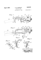
- Figure 1 is a side elevation of an artificial hand or hook constructed in'accordance with the inlo ventionslrowing therein bydotted lines a table knife held for use in cutting material .such as meat or edibles.
- Figure 2 is a top plan-eview thereof showing by dotted lines a table knife in several positions, 15 one (being for jabbing or piercing action and the other a cutting position.
- Figure -3 is an outer end elevation.
- Figure 4 is a fragmentary eievation of one of thejfingers at its ti g
- Figure 5 is a. view similar to Figure 4 showing the other finger at its tip.
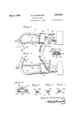
- Figure 6 is a plan View of a-slight' modification.
- Figure 7 is a view similar to Figure '6 looking toward the opposite side thereof.
- Figure 8 is a sectional view on the line 88 of Figure *6.
- Figure 9 is a sectional view on the line 9-41 01 Figure -6. l
- Figure 1 0 is a view similar to Figure 9 'showso ing a slight modification of the meeting faces of the'tips.
- i 1 Figure 11 is a view similar to Figure 10 showing a still further modification of the meeting faces of the tips. s5
- the artificial hand or natural hand-substitute comprises a coupling A adapted for, detachable fastening with a stump member of "any conventional tomnwhich latter #5 is designed-for connection with an am after amputation of the hand or .a part of said'rarm, the coupling A being no part of the present invention and beinglshown merely to identify a mode or I method of attachment or the artificial hand or so hand substitute. 7 I q
- the coupling A carries as apart thereof a block is constituting what.
- a headand is'formedwith a stationary finger H, the major portion thereof being relatively straight while the 55 adjoining inner end E2 of said finger is outwardly curved to offset the same from the block or head as, the latter being cut away at one side to provide a pivot'ear it for the mounting therewith of the pivot end M of a movable finger l5, the latter for a major portion of its length being gradually curved and its ear i i receiving a pivot N5, the latter being engaged in the ear l3 and in this manner the said finger i5 is swingingly related to the stationary finger l l.
- the fingers i i and i5 carry hook-like tips I! and i8 respectively, they being integral therewith and the tip ll is cut into at its inner side to providea seat is for the tip 58 which is offset by the bight 2:; from the finger is; the inner faces of said tips ll and iii are serrated or roughened at 2l'toprovide firmly gripping surfaces thereto andthese surfaces are in confronting relation to each other.
- the seat iii in the tip I'i closely accommodates the tip 58 when the finger I5 is closed or swung toward the finger ll;
- These tips H and iii are curved in a matched relation to each other and are disposed at-an acute lateral angle to the fin- .gers. l l and i5 with their free ends rounded at 22 and likewise the outer surfaces 23 of such tips are rounded and smooth of finish.
- the movable finger l5 is actuated and controlled by'a trigger 3G having an eye St for the attachmerit thereto of a pull cord, the trigger being pivotally mounted at the inner end l2 of the movablew finger i5 andioperating a link 32 loosely connected therewith, which link is also loosely connectedto'a lever 33 on a stud rock shaft 34 operating as an eccentric and this shaft cooperates and in its construction corresponds with the subject matter of U; S. Letters Patent #1346954, dated February 23, 1932 the shaft 34 being'tensioned by a spring 35 anchored thereto and also to the block it.
- the working of this shaft 34 and its association with the pivot end of the finger i5 is clearly defined and set forth in the aforesaid patent and constitutes no part of the present invention.
- the table knife 36 On operation of the movable finger E5 the table knife 36, that is, the handle 31 thereof can in one instance be interposed between the fingers TI I and 15 as is shown in Figure 1 of the drawings so that the blade or knife 35 can be grasped firmly between the tips H and IS with thehandle 31 angularly disposed and saddled upon the band 25, thus in this position the said knife can be conveniently operated for cutting purposes.
- the knife 35 has its handle seated between the inner end of the fingers l l and with the handle grasped by the tips ll and i8 and in this position such knife can be used for jabbing or piercing purposes.
- the heel edge of such knife will constitute a fulcrum against the portion 26 of the stationary finger i, while the movable finger if: under the action of the band 2-5 will be forced against such knife and the tips l I and E3 of these fingers will firmly and securely grasp the knife to positively hold the same under manipulation thereof in the use of the same.
- the knife 36 is shown resting crosswise upon the trigger 36 with the blade of such knife grasped or gripped between the tips l1 and !8, these forming pincers and it should be obvious that a nail or implement, of hand operable type can be firmly pinched or grasped by the tips for the secure holding thereof, the serrated or roughened faces 21 of said tips being efiective to prevent any possible slipping of the part or article held by the artificial hand or natural hand substitute.
- the stubs 2i and 28 also constitute grippers, pincers and abutments for articles to be grasped and held by the fingers II and L: of the artificial hand.
- the opening and closing of the finger I5 is automatically accomplished by operating the trigger 38, the latter being controlled by a pull cord or cable which is manipulated by shoulder or arm movement of the wearer of the artificial hand.
- the fingers 42 and 43 at their inner ends are formed with guard prongs 46 and 41 respectively, these being protective for the rubber band or bands 48, while the finger 42 carries a knob, bump or protuberance 49, the latter functioning as the joint of the thumb of a natural hand to provide a fulcrum or rest at this point of the finger.
- the shape of the shoulders 40, 4!, Mi, Al, 44 and 45 may be varied so as to function in a positive manner for the grasping or gripping of the articles heretofore named, as well as paper, cloth or anything of sheetkind.
- This shoulder formation at the tips 38 and 39 materially strengthens the same.
- the prongs 46 and 41 in addition to serving as guards will also constitute a rest or an abutment has located beneath its 'head a series of antifriction balls 5
- this pivotal joint eliminates all friction in the working of the pivoted finger so that there is no liability of resistance at the pivot or the possibility of the sticking of the pivotal finger, it being freely movable.
- stationary and movable fingers offset with relation to each other, the movable finger being substantially straight and the stationary finger being curved outwardly, hook-like tips at the outer ends of said fingers and disposed lengthwise of each other, contacting stubs projected outwardly from said tips and parallel with the straight finger when in contacting relation to each other, the tip of the stationary finger being disposed crosswise of the tip of the movable finger, irregular formations on the confronting faces of the tips and coextensive with the lengths thereof for the overlapping of the fingers with each other when brought together, and prongs approaching each other and formed on the fingers close to the-inner ends of said fingers.
Landscapes
- Health & Medical Sciences (AREA)
- Orthopedic Medicine & Surgery (AREA)
- Transplantation (AREA)
- Cardiology (AREA)
- Oral & Maxillofacial Surgery (AREA)
- Engineering & Computer Science (AREA)
- Biomedical Technology (AREA)
- Heart & Thoracic Surgery (AREA)
- Vascular Medicine (AREA)
- Life Sciences & Earth Sciences (AREA)
- Animal Behavior & Ethology (AREA)
- General Health & Medical Sciences (AREA)
- Public Health (AREA)
- Veterinary Medicine (AREA)
- Knives (AREA)
Description
fl- 6, 9 5- 1 D. w. DORRANCE ARTIFICIAL HAND Fi-led Maroh27, 1953 2 Sheets-Sheet 1 flak/7d Z7. fivrrance,
ATTORNEY fl- 1935- D. w. DORRANCE 2,010,751
ARTIFICIAL HAND Filed March v, 19:5 2 Sheets-Sheet 2 ,Ua/v i/ol ET. liorrqnae/ INVENTOR ATT RNIY Patented Aug. 6, 1935 mu TED STATE-S A E O 1 Claim. (tits-42) "Ilhe invention relates to an artificial hand and "more especially to a jaw hook as a natural hand substitute where the amputation of the hand of aperson has taken place. 1 The primary obj ect of the invention .is the provision of a structure of this character wherein them-care .manged relatively movable'fingers or jaws, these being .so bent or shaped and carrying thumbs Ior protuberancesso positioned as to offect cooperation with the fingers or'jaws, whereby a table knife can be grasped and manipulated in .a natural manner for thepurposes intended thereof. 1
Another object of the invention is the provision of a structure "of this character, wherein the table knife, spoon, fork or other implement of a. like nature may be conveniently held and manipulated without liability of displacement or the working loose thereotand in the holding of a knife the pitch of its blade can be regulated for cutting purposes as in carving or the cutting. of meats or so heldthat it can be .jabbed or pierced. .A further object of the invention is the provisionof a structure of this character, wherein the fingers and adjunct portions thereof are so shaped and arranged as to enable the firm and secure grasping of cutlery or table implements and sustained in workable position for the convenient use thereof, the construction being novel in form and thereby afiording a substitute for the natural hand to meet the requirements of the latter without inconvenience. or awkwardness'resulting from the artificial characteristic of the A still further object of the invention is the provision of a construction of this character wherein wire, thread, cord or other wire-like or cord-like material can be conveniently grasped and held without slippagetc an equal degree as may he'hadby the use of the natural hand, the construction also functioning for the holding and manipulation of varying instruments orimplements, as well as nails to be driven byya hammer orany article that may beconvenien-tlyheld by the natural hand. a I .A- still further object of the invention is the provision of a construction of this character which is an improvement over the subject matterof U. S. Patent #1346354, dated February 23, 1932., withniceties inthe refinement thereof'ancl in the formation of certain parts or adjuncts so as to materially better the working conditions and assure firmgripping qualities of various articles and in the operation of the same. r 1
With these and otherobjec-ts in View, the in-.
Figure '12 is "a sectional venti-on consists in the features of construction,
combination and arrangement of parts as will behereinafter more fully described in detail, illustrated in the accompanying drawings, which disclose the preferred embodiment :of the inven- ".5 tion, and pointed out in the claim hereunto 341- pended. :1 i
in the accompanying drawings Figure 1 is a side elevation of an artificial hand or hook constructed in'accordance with the inlo ventionslrowing therein bydotted lines a table knife held for use in cutting material .such as meat or edibles.
. Figure 2 is a top plan-eview thereof showing by dotted lines a table knife in several positions, 15 one (being for jabbing or piercing action and the other a cutting position.
Figure -3 is an outer end elevation.
Figure 4 is a fragmentary eievation of one of thejfingers at its ti g Figure 5 is a. view similar to Figure 4 showing the other finger at its tip.
Figure 6 is a plan View of a-slight' modification. Figure 7 is a view similar to Figure '6 looking toward the opposite side thereof. 95 Figure 8 is a sectional view on the line 88 of Figure *6.
Figure 9 is a sectional view on the line 9-41 01 Figure -6. l
Figure 1 0 is a view similar to Figure 9 'showso ing a slight modification of the meeting faces of the'tips. i 1 Figure 11 is a view similar to Figure 10 showing a still further modification of the meeting faces of the tips. s5
view on the line .1 2+1! of Figure "6..
Similar reference characters indicate corresponding parts throughout the several views in the drawings. 40
Referring to'the drawings in detail, particularly Figures 1 to :5 thereof, the artificial hand or natural hand-substitute comprises a coupling A adapted for, detachable fastening with a stump member of "any conventional tomnwhich latter #5 is designed-for connection with an am after amputation of the hand or .a part of said'rarm, the coupling A being no part of the present invention and beinglshown merely to identify a mode or I method of attachment or the artificial hand or so hand substitute. 7 I q The coupling A carries as apart thereof a block is constituting what. might be termed a headand is'formedwith a stationary finger H, the major portion thereof being relatively straight while the 55 adjoining inner end E2 of said finger is outwardly curved to offset the same from the block or head as, the latter being cut away at one side to provide a pivot'ear it for the mounting therewith of the pivot end M of a movable finger l5, the latter for a major portion of its length being gradually curved and its ear i i receiving a pivot N5, the latter being engaged in the ear l3 and in this manner the said finger i5 is swingingly related to the stationary finger l l.
The fingers i i and i5 carry hook-like tips I! and i8 respectively, they being integral therewith and the tip ll is cut into at its inner side to providea seat is for the tip 58 which is offset by the bight 2:; from the finger is; the inner faces of said tips ll and iii are serrated or roughened at 2l'toprovide firmly gripping surfaces thereto andthese surfaces are in confronting relation to each other.
The seat iii in the tip I'i closely accommodates the tip 58 when the finger I5 is closed or swung toward the finger ll; These tips H and iii are curved in a matched relation to each other and are disposed at-an acute lateral angle to the fin- .gers. l l and i5 with their free ends rounded at 22 and likewise the outer surfaces 23 of such tips are rounded and smooth of finish.
Formed on the fingers M and [5 close to the pivot is connecting the swinging finger are shoulj'ders for abutment therewith of an endless elastic band 25, the latter encircling both fingers H and l5,'the band'being relatively wide and constituting a tensioning medium for urging the movable finger l5 toward the stationary finger l l 'for the positive closing or bringing together of these fingers and upon the opening thereof or the separation of said fingers the band 25 will tension the same and operate the movable finger 15. The shoulders 24 prevent the working outwardly of the band 25 on thefingers I l and I5 in the direction of the free ends or tips H and I8 thereof.
At the bight 26 between the tip [8 and finger l5 and also at the meeting point 26 of the finger l i with said bight are outwardly projecting stubs or protuberances El and 28 respectively, these gradually tapering outwardly and being formed with rounded ends 29. When the finger I5 is in closed position with respect to the finger l l the stubs or protuberances are in contact with each other and in parallelism so as to match one with the other and the purpose thereof will be hereinafter fully described. 7
The movable finger l5 is actuated and controlled by'a trigger 3G having an eye St for the attachmerit thereto of a pull cord, the trigger being pivotally mounted at the inner end l2 of the movablew finger i5 andioperating a link 32 loosely connected therewith, which link is also loosely connectedto'a lever 33 on a stud rock shaft 34 operating as an eccentric and this shaft cooperates and in its construction corresponds with the subject matter of U; S. Letters Patent #1346954, dated February 23, 1932 the shaft 34 being'tensioned by a spring 35 anchored thereto and also to the block it. The working of this shaft 34 and its association with the pivot end of the finger i5 is clearly defined and set forth in the aforesaid patent and constitutes no part of the present invention.
On operation of the movable finger E5 the table knife 36, that is, the handle 31 thereof can in one instance be interposed between the fingers TI I and 15 as is shown in Figure 1 of the drawings so that the blade or knife 35 can be grasped firmly between the tips H and IS with thehandle 31 angularly disposed and saddled upon the band 25, thus in this position the said knife can be conveniently operated for cutting purposes.
In Figure 2 of the drawings the knife 35 has its handle seated between the inner end of the fingers l l and with the handle grasped by the tips ll and i8 and in this position such knife can be used for jabbing or piercing purposes. In both instances of the grasping of the knife as in Figures 1 and 2 of the drawings, the heel edge of such knife will constitute a fulcrum against the portion 26 of the stationary finger i, while the movable finger if: under the action of the band 2-5 will be forced against such knife and the tips l I and E3 of these fingers will firmly and securely grasp the knife to positively hold the same under manipulation thereof in the use of the same.
In Figure 2 the knife 36 is shown resting crosswise upon the trigger 36 with the blade of such knife grasped or gripped between the tips l1 and !8, these forming pincers and it should be obvious thata nail or implement, of hand operable type can be firmly pinched or grasped by the tips for the secure holding thereof, the serrated or roughened faces 21 of said tips being efiective to prevent any possible slipping of the part or article held by the artificial hand or natural hand substitute. The stubs 2i and 28 also constitute grippers, pincers and abutments for articles to be grasped and held by the fingers II and L: of the artificial hand.
' The opening and closing of the finger I5 is automatically accomplished by operating the trigger 38, the latter being controlled by a pull cord or cable which is manipulated by shoulder or arm movement of the wearer of the artificial hand.
In Figures 6 to 11 of the drawings there is showing a slight modification of the invention, wherein the tips 38 and 39 respectively, these corresponding to the tips l'a' and ill, have their inner faces, in the direction of the length thereof, out into to provide overlapped interfitting shoulders 40 and M and All and M respectively, as in Figures 9 and 10 while the fingers 42 and 43 respectively, which are the equivalent to the fingers I! and I5, have their inner faces immediately next to the tips 38 and 39 shaped at 44 and 45 as in Figure 11 for the overlapped and interfitting relationship as effected at the shoulders 48 and M and the purpose of this interfitting and overlap is to enable a wire, cord, cable or other like article to be grasped and firmly held against slippage when engaged by the artificial hand.
The fingers 42 and 43 at their inner ends are formed with guard prongs 46 and 41 respectively, these being protective for the rubber band or bands 48, while the finger 42 carries a knob, bump or protuberance 49, the latter functioning as the joint of the thumb of a natural hand to provide a fulcrum or rest at this point of the finger. I
It is of course to be understood that the shape of the shoulders 40, 4!, Mi, Al, 44 and 45 may be varied so as to function in a positive manner for the grasping or gripping of the articles heretofore named, as well as paper, cloth or anything of sheetkind. This shoulder formation at the tips 38 and 39 materially strengthens the same. The prongs 46 and 41 in addition to serving as guards will also constitute a rest or an abutment has located beneath its 'head a series of antifriction balls 5|, these traveling in a suitable raceway 52 formed in the head of the pivot and the adjacent pivotal end 53 of the finger 42. Likewise, between the end 53 and the companion portion 54 of the finger 43 is a series of antifriction balls 55, these traveling in a raceway 56 in said companion portion of the finger 33.
Thus it will be seen. that this pivotal joint eliminates all friction in the working of the pivoted finger so that there is no liability of resistance at the pivot or the possibility of the sticking of the pivotal finger, it being freely movable.
What is claimed is:-
In an artificial hand of the character described, stationary and movable fingers offset with relation to each other, the movable finger being substantially straight and the stationary finger being curved outwardly, hook-like tips at the outer ends of said fingers and disposed lengthwise of each other, contacting stubs projected outwardly from said tips and parallel with the straight finger when in contacting relation to each other, the tip of the stationary finger being disposed crosswise of the tip of the movable finger, irregular formations on the confronting faces of the tips and coextensive with the lengths thereof for the overlapping of the fingers with each other when brought together, and prongs approaching each other and formed on the fingers close to the-inner ends of said fingers.
DAVID W. DORRANCE.
Priority Applications (1)
| Application Number | Priority Date | Filing Date | Title |
|---|---|---|---|
| US663037A US2010751A (en) | 1933-03-27 | 1933-03-27 | Artificial hand |
Applications Claiming Priority (1)
| Application Number | Priority Date | Filing Date | Title |
|---|---|---|---|
| US663037A US2010751A (en) | 1933-03-27 | 1933-03-27 | Artificial hand |
Publications (1)
| Publication Number | Publication Date |
|---|---|
| US2010751A true US2010751A (en) | 1935-08-06 |
Family
ID=24660246
Family Applications (1)
| Application Number | Title | Priority Date | Filing Date |
|---|---|---|---|
| US663037A Expired - Lifetime US2010751A (en) | 1933-03-27 | 1933-03-27 | Artificial hand |
Country Status (1)
| Country | Link |
|---|---|
| US (1) | US2010751A (en) |
-
1933
- 1933-03-27 US US663037A patent/US2010751A/en not_active Expired - Lifetime
Similar Documents
| Publication | Publication Date | Title |
|---|---|---|
| EP2160273B1 (en) | Multipurpose shears | |
| US4899482A (en) | Multi-utility fishing tool | |
| US449031A (en) | Tobacco-knife | |
| US2089177A (en) | Tweezer | |
| US987095A (en) | Fruit-clipper. | |
| US4315369A (en) | Food cutting and grasping implement | |
| US993720A (en) | Bone-fork. | |
| US2540255A (en) | Fruit clipper | |
| US1117740A (en) | Tweezers for fishbones. | |
| US2010751A (en) | Artificial hand | |
| US964788A (en) | Fruit-picker. | |
| US1101331A (en) | Fruit-clipper. | |
| US2676404A (en) | Spring opener for scissors | |
| US2055270A (en) | Pincers | |
| US1444976A (en) | Fruit-cutting device | |
| US2495677A (en) | Pruning shears | |
| US2387032A (en) | Knife | |
| US20100064528A1 (en) | Scissors for accommodating different sized hands and for requiring a minimal force to close | |
| US1456844A (en) | Potjltby-pltjckiitg device | |
| US1374768A (en) | David rtjppeb | |
| US1010784A (en) | Grape and orange clipper. | |
| US1081896A (en) | Cuticle-clipper. | |
| US443178A (en) | Thomas | |
| US244891A (en) | Finger-nail trimmer | |
| US2030785A (en) | Artificial hand |