US2010551A - Device for reading of x-ray films - Google Patents
Device for reading of x-ray films Download PDFInfo
- Publication number
- US2010551A US2010551A US2010551DA US2010551A US 2010551 A US2010551 A US 2010551A US 2010551D A US2010551D A US 2010551DA US 2010551 A US2010551 A US 2010551A
- Authority
- US
- United States
- Prior art keywords
- box
- compartment
- film
- light
- reading
- Prior art date
- Legal status (The legal status is an assumption and is not a legal conclusion. Google has not performed a legal analysis and makes no representation as to the accuracy of the status listed.)
- Expired - Lifetime
Links
- 239000011521 glass Substances 0.000 description 16
- 238000007689 inspection Methods 0.000 description 14
- 239000002184 metal Substances 0.000 description 8
- 230000037431 insertion Effects 0.000 description 4
- 238000003780 insertion Methods 0.000 description 4
- 230000000694 effects Effects 0.000 description 3
- 230000015572 biosynthetic process Effects 0.000 description 1
- 239000004020 conductor Substances 0.000 description 1
- 238000009792 diffusion process Methods 0.000 description 1
- 238000005286 illumination Methods 0.000 description 1
Images
Classifications
-
- G—PHYSICS
- G02—OPTICS
- G02B—OPTICAL ELEMENTS, SYSTEMS OR APPARATUS
- G02B27/00—Optical systems or apparatus not provided for by any of the groups G02B1/00 - G02B26/00, G02B30/00
- G02B27/02—Viewing or reading apparatus
- G02B27/022—Viewing apparatus
- G02B27/024—Viewing apparatus comprising a light source, e.g. for viewing photographic slides, X-ray transparancies
- G02B27/025—Viewing apparatus comprising a light source, e.g. for viewing photographic slides, X-ray transparancies and magnifying means
-
- G—PHYSICS
- G02—OPTICS
- G02B—OPTICAL ELEMENTS, SYSTEMS OR APPARATUS
- G02B27/00—Optical systems or apparatus not provided for by any of the groups G02B1/00 - G02B26/00, G02B30/00
- G02B27/02—Viewing or reading apparatus
- G02B27/022—Viewing apparatus
- G02B27/024—Viewing apparatus comprising a light source, e.g. for viewing photographic slides, X-ray transparancies
Definitions
- This invention has to do with a device for the reading of X-ray films.
- the art of interpreting X-ray films is one which deals largely with shadows and varying density effects.
- the film is lighted by suitable light source such as an incandescent lamp, and inasmuch as different films vary in density, an arrangement is provided to vary the incandescence of the lamp.
- suitable light source such as an incandescent lamp
- the device also includes means for diffusing the light so that the film is subjected more or less uniformly to light over its surfaces, and the arrangement is such that the film may be quickly placed in position or removed.
- a lens is preferably incorporated in the device which is used to magnify the showing on the film, and this is particularly useful in the detail consideration of small films, for example, films of the bony structure of a jaw.
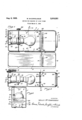
- Fig. 1 is a view of a device constructed in accordance with the invention, the view being in side elevation, and with one side of the device open to show the interior structure.
- Fig. 2 is a sectional view taken substantially on line 22 of Fig. 1.
- Fig. 3 is a sectional view taken on line 3-3 of Fig. 1.
- the device for carrying out the invention may be of a simple structure and in fact it may be in the form of a casing or box preferably arranged to be suitably mounted.
- the box may be made of sheet metal.
- the device may be in the form of a box having a side wall I, other walls 2 and 3 which may be termed top and bottom walls, inasmuch as these happen to be top and bottom walls as the device is shown herein, walls 4 and 5, and another side wall 6 which may be hinged to the major portion of the device as at 1.
- the wall 6 may have a rim 8 for telescopingly fitting over the main portion of the box; Any suitable fastening means may be used for holding the wall 6 in place.
- the box may be suitably mounted, as for example, on a hinge H) so that it may be swung 50 outwardly from a wall or other support I I for use and swung into close proximity therewith when not in use.
- a light source preferably an incandescent lamp.
- a suitable base or support therefore is shown at l5 fastened to the end wall 1934, Serial No. 714,580
- the lamp is illustrated at I8 in a socket l9 preferably equipped with a controlling device for controlling, varying or changing the ineandescence of the lamp.
- a controlling device for controlling, varying or changing the ineandescence of the lamp.
- Such controlling devices are now available on the market and one is illustrated herein within a housing 20.
- the control is effected by shifting flexible elements such as small chains, cords or small cables 2
- the shaft is journaled in the box and has an outside operating piece 24. By turning the member 24 the incandescence of the lamp is varied.
- alight diffusing device 25 advantageously in the form of a piece of glass of opaleseent or frosted variety.
- This glass may be held in place by wings 26 struck out of the sheet metal sides of the box and the glass may be placed into or removed from the closure by opening of the wall 6.
- This piece of glass divides the box into two compartments with the lamp in one of the compartments.
- some of the walls may be provided with struck out portions 21. to thus'form louvers for the flow of air currents through the light compartment, thus serving to cool the same.
- the film compartment is on the right hand side of the diffusion glass as Fig. l is viewed, and the walls I and 6 are slotted as at 30 and 3
- These slots may be provided by striking out Wings 30 or 3
- may be of generous portions making it very easy to insert a film with the struck-out portions 32 serving to guide the film into place and serving to in effect reduce the size of the openings 30 and 3
- the end 4 may be provided with a collar like formation 35 of circular form for holding a magnifying glass or lens 36.
- the end of the collar may be fashioned over as at 31 for abutting against one side of the lens and struck out portions 38 may hold the lens from the opposite side.
- the device In the use of the device an operator may stand so as to look into the box through the lens 36 and then the film may be positioned by insertion through one of the slots 30 or 3
- the glass 36 magnifies the size of the forms on the film so that they may be studied in detail and the incandescence of the lamp l8 may be varied by manipulation of the operating piece 24.
- this light may be varied in the consideration of shadows of varying densities in a given film and may be varied also in consideration of separate films of difierent densities.
- the lamp I8 is advantageously one of the variety which provides illumination simulating daylight. To this end the lamp may be blued. In some cases, however, where a dark room effect is desired, a red light may be used.
- a device for reading X-ray films comprising a box, a light diffusing glass intermediate the ends of the box dividing the box into compartments, a light source in one compartment, said box being of sheet metal, one or more walls of the other compartment having inwardly struck wings providing openings for the insertion of a film located relatively close to the diffusing glass and remote from the end of the box at the second compartment, and the end of the box at the second compartment having an inspection opening therein.
- a device for reading X-ray films comprising a box, a light difiusing glass intermediate the ends of the box dividing the box into compartments, a light source in one compartment, said box being of sheet metal, one or more walls of the other compartment having inwardly struck wings providing openings for the insertion of a film, and the end of the box at the second compartment having an inspection opening therein, said wings extending angularly and inwardly toward the light diffusing glass and away from the inspection opening.
- a device for reading X-ray films comprising a box, a light diffusing glass intermediate the ends of the box dividing the box into compartments, and a light source in one compartment, said box being of sheet metal, one or more walls of the other compartment having inwardly struck wings providing openings for the insertion of a film, and the end of the box at the second compartment having an inspection opening therein, said wings extending angularly and inwardly toward the light diffusing glass and away from the inspection opening to define the area on the film which is visible from the inspection opening, and a magnifying lens in the inspection opening.
- a device for reading X-ray films comprising an elongated box, a light source in one end of the box, an inspection opening at the other end of the box, a light difiusing glass between the inspection opening and the light source and spaced from the inspection opening, the box walls having one or more slots therein for the passage therethrough of a film between the light diffusing glass and the inspection opening, and means hingedly mounting the box to a support at a corner adjacent the end of the box having the light source.
- a device for reading X-ray films comprising, a box, a cover for the box for closing the same and openable for access to the interior of the box, a light difiusing element in the box dividing the same into compartments, a light source in one compartment, the wall of the box opposite the compartment with the light source having an inspection opening therein, a lens in said opening, some of the walls of the box being of sheet metal, at least one of the sheet metal walls having a slot therein formed by cut-away sheet metal, the said slot communicating with the compartment next adjacent the inspection opening, and said slot being positioned in close proximity to the light difiusing element whereby film may be passed therethrough into the compartment next adjacent the inspection opening and positioned immediately adjacent the light difiusing element, and means on the box adjacent the end of the box with the light compartment for hingeably mounting the box to a support.
Landscapes
- Physics & Mathematics (AREA)
- General Physics & Mathematics (AREA)
- Optics & Photonics (AREA)
- Apparatus For Radiation Diagnosis (AREA)
Description
Aug. 6, 1935. w. McCONALOGUE 2,010,551
DEVICE FOR READING OF X-RAY FILMS Filed March 8, 1934' I! HIIII INVENTOR. W551 i Y H CON/7t 06 vi 6%, wfiw @M ATTORNEY):
Patented Aug. 6, 1935 UNITED STATES PATENT OFFICE Application March 8,
Claims.
This invention has to do with a device for the reading of X-ray films. The art of interpreting X-ray films is one which deals largely with shadows and varying density effects. In dentistry, for
5 example, the use of the X-ray in considering and studying the bony structure of the jaw is increasing, as the condition of such bonystructure may even indicate in advance conditions to be expected in teeth.
According to the invention the film is lighted by suitable light source such as an incandescent lamp, and inasmuch as different films vary in density, an arrangement is provided to vary the incandescence of the lamp. The device also includes means for diffusing the light so that the film is subjected more or less uniformly to light over its surfaces, and the arrangement is such that the film may be quickly placed in position or removed. A lens is preferably incorporated in the device which is used to magnify the showing on the film, and this is particularly useful in the detail consideration of small films, for example, films of the bony structure of a jaw.
In the accompanying drawing:
Fig. 1 is a view of a device constructed in accordance with the invention, the view being in side elevation, and with one side of the device open to show the interior structure.
Fig. 2 is a sectional view taken substantially on line 22 of Fig. 1.
Fig. 3 is a sectional view taken on line 3-3 of Fig. 1.
The device for carrying out the invention may be of a simple structure and in fact it may be in the form of a casing or box preferably arranged to be suitably mounted. The box may be made of sheet metal. As shown in Fig. 1 the device may be in the form of a box having a side wall I, other walls 2 and 3 which may be termed top and bottom walls, inasmuch as these happen to be top and bottom walls as the device is shown herein, walls 4 and 5, and another side wall 6 which may be hinged to the major portion of the device as at 1. The wall 6 may have a rim 8 for telescopingly fitting over the main portion of the box; Any suitable fastening means may be used for holding the wall 6 in place.
The box may be suitably mounted, as for example, on a hinge H) so that it may be swung 50 outwardly from a wall or other support I I for use and swung into close proximity therewith when not in use. One end of the box is arranged to accommodate a light source, preferably an incandescent lamp. A suitable base or support therefore is shown at l5 fastened to the end wall 1934, Serial No. 714,580
5 as by means of bolts or the like l6 while the conductor is shown at IT leading into the box. The lamp is illustrated at I8 in a socket l9 preferably equipped with a controlling device for controlling, varying or changing the ineandescence of the lamp. Such controlling devices are now available on the market and one is illustrated herein within a housing 20. The control is effected by shifting flexible elements such as small chains, cords or small cables 2| and 22 which extend into the housing 20 and are oppositely wound upon a control shaft 23. The shaft is journaled in the box and has an outside operating piece 24. By turning the member 24 the incandescence of the lamp is varied.
Forwardly of the lamp is positioned alight diffusing device 25 advantageously in the form of a piece of glass of opaleseent or frosted variety. This glass may be held in place by wings 26 struck out of the sheet metal sides of the box and the glass may be placed into or removed from the closure by opening of the wall 6. This piece of glass divides the box into two compartments with the lamp in one of the compartments. For ventilating purposes some of the walls may be provided with struck out portions 21. to thus'form louvers for the flow of air currents through the light compartment, thus serving to cool the same.
The film compartment is on the right hand side of the diffusion glass as Fig. l is viewed, and the walls I and 6 are slotted as at 30 and 3| so that a film may be passed into or through the compartment on the side of the glass opposite the light source. These slots may be provided by striking out Wings 30 or 3| and leaving them substantially in the position as shown, thus to define the portion of the film visible for consideration, and to also serve to keep out other light. Thus the slots 30 and 3| may be of generous portions making it very easy to insert a film with the struck-out portions 32 serving to guide the film into place and serving to in effect reduce the size of the openings 30 and 3|.
The end 4 may be provided with a collar like formation 35 of circular form for holding a magnifying glass or lens 36. The end of the collar may be fashioned over as at 31 for abutting against one side of the lens and struck out portions 38 may hold the lens from the opposite side.
In the use of the device an operator may stand so as to look into the box through the lens 36 and then the film may be positioned by insertion through one of the slots 30 or 3|. The glass 36 magnifies the size of the forms on the film so that they may be studied in detail and the incandescence of the lamp l8 may be varied by manipulation of the operating piece 24. As above mentioned this light may be varied in the consideration of shadows of varying densities in a given film and may be varied also in consideration of separate films of difierent densities. The lamp I8 is advantageously one of the variety which provides illumination simulating daylight. To this end the lamp may be blued. In some cases, however, where a dark room effect is desired, a red light may be used.
I claim:
1. A device for reading X-ray films, comprising a box, a light diffusing glass intermediate the ends of the box dividing the box into compartments, a light source in one compartment, said box being of sheet metal, one or more walls of the other compartment having inwardly struck wings providing openings for the insertion of a film located relatively close to the diffusing glass and remote from the end of the box at the second compartment, and the end of the box at the second compartment having an inspection opening therein.
2. A device for reading X-ray films, comprising a box, a light difiusing glass intermediate the ends of the box dividing the box into compartments, a light source in one compartment, said box being of sheet metal, one or more walls of the other compartment having inwardly struck wings providing openings for the insertion of a film, and the end of the box at the second compartment having an inspection opening therein, said wings extending angularly and inwardly toward the light diffusing glass and away from the inspection opening.
3. A device for reading X-ray films, comprising a box, a light diffusing glass intermediate the ends of the box dividing the box into compartments, and a light source in one compartment, said box being of sheet metal, one or more walls of the other compartment having inwardly struck wings providing openings for the insertion of a film, and the end of the box at the second compartment having an inspection opening therein, said wings extending angularly and inwardly toward the light diffusing glass and away from the inspection opening to define the area on the film which is visible from the inspection opening, and a magnifying lens in the inspection opening.
4. A device for reading X-ray films, comprising an elongated box, a light source in one end of the box, an inspection opening at the other end of the box, a light difiusing glass between the inspection opening and the light source and spaced from the inspection opening, the box walls having one or more slots therein for the passage therethrough of a film between the light diffusing glass and the inspection opening, and means hingedly mounting the box to a support at a corner adjacent the end of the box having the light source.
5. A device for reading X-ray films comprising, a box, a cover for the box for closing the same and openable for access to the interior of the box, a light difiusing element in the box dividing the same into compartments, a light source in one compartment, the wall of the box opposite the compartment with the light source having an inspection opening therein, a lens in said opening, some of the walls of the box being of sheet metal, at least one of the sheet metal walls having a slot therein formed by cut-away sheet metal, the said slot communicating with the compartment next adjacent the inspection opening, and said slot being positioned in close proximity to the light difiusing element whereby film may be passed therethrough into the compartment next adjacent the inspection opening and positioned immediately adjacent the light difiusing element, and means on the box adjacent the end of the box with the light compartment for hingeably mounting the box to a support.
WESLEY MCCONALOGUE.
Publications (1)
| Publication Number | Publication Date |
|---|---|
| US2010551A true US2010551A (en) | 1935-08-06 |
Family
ID=3427268
Family Applications (1)
| Application Number | Title | Priority Date | Filing Date |
|---|---|---|---|
| US2010551D Expired - Lifetime US2010551A (en) | Device for reading of x-ray films |
Country Status (1)
| Country | Link |
|---|---|
| US (1) | US2010551A (en) |
Cited By (4)
| Publication number | Priority date | Publication date | Assignee | Title |
|---|---|---|---|---|
| US2515921A (en) * | 1948-01-24 | 1950-07-18 | Blum Harry | Film viewing device |
| US2594390A (en) * | 1950-12-26 | 1952-04-29 | Brumberger Sydney | Device for viewing slides |
| US2630642A (en) * | 1947-05-06 | 1953-03-10 | Mast Dev Company Inc | Slide viewer |
| US4408850A (en) * | 1981-08-10 | 1983-10-11 | Norek George G | Drawing table |
-
0
- US US2010551D patent/US2010551A/en not_active Expired - Lifetime
Cited By (4)
| Publication number | Priority date | Publication date | Assignee | Title |
|---|---|---|---|---|
| US2630642A (en) * | 1947-05-06 | 1953-03-10 | Mast Dev Company Inc | Slide viewer |
| US2515921A (en) * | 1948-01-24 | 1950-07-18 | Blum Harry | Film viewing device |
| US2594390A (en) * | 1950-12-26 | 1952-04-29 | Brumberger Sydney | Device for viewing slides |
| US4408850A (en) * | 1981-08-10 | 1983-10-11 | Norek George G | Drawing table |
Similar Documents
| Publication | Publication Date | Title |
|---|---|---|
| US3077536A (en) | Two-way lighting fixture | |
| US2010551A (en) | Device for reading of x-ray films | |
| US2214209A (en) | Dial lighting | |
| US1786787A (en) | Window-drape illuminator | |
| US2242525A (en) | Illuminating device | |
| US2913569A (en) | Lighting apparatus for photography | |
| US2513576A (en) | Transparency viewer | |
| US3111274A (en) | Cover for photoflash gun attachment | |
| US2417802A (en) | Device to facilitate mounting specimens on microscope slides | |
| US1683599A (en) | Luminair | |
| US1591957A (en) | Portable x-ray viewing box | |
| US1911962A (en) | Radiograph illuminator | |
| US1108999A (en) | Annunciator-cabinet. | |
| US1736012A (en) | Illuminating means for photographic cabinets | |
| USRE15624E (en) | Illuminating device | |
| US2258014A (en) | Illuminating device for enlarging or projecting apparatus | |
| USRE17418E (en) | Combined outside light | |
| US1470708A (en) | Camera | |
| US1781282A (en) | Mail chute | |
| US1836669A (en) | Casing for translucent name or number plate | |
| US2012940A (en) | Wet fhjf transfer illuminator | |
| GB350692A (en) | Developing unit for x-ray and other photographic films | |
| US1616269A (en) | Combined outside light, mail box, and house number | |
| US1642339A (en) | Wall light | |
| US1915666A (en) | House-numbering device |